1
IMPORTANT SAFETY INSTRUCTIONS
WARNING: TO REDUCE THE RISK OF FIRE. ELECTRIC
SHOCK, OR INJURY TO PERSONS, OBSERVE THE
FOLLOWING:
A. Use this unit only in the manner intended by the manufacturer. If
you have questions, contact the manufacturer.
B. Before servicing or cleaning unit, switch power off at service
panel and lock service panel to prevent power from being
switched on accidentally.
When the service disconnecting means cannot be locked, securely
fasten a prominent warning device, such as a tag, to the service
panel.
• Suitable for use with solid state speed controls.
CAUTION: For general ventilating use only. Do not use to exhaust
hazardous or explosive materials and vapors.
INSTALLATION INSTRUCTIONS
WARNING: TO REDUCE THE RISK OF FIRE, ELECTRIC
SHOCK, OR INJURY TO PERSONS, OBSERVE THE
FOLLOWING:
A. Installation work and electrical wiring must be done by qualified
person(s) in accordance with all applicable codes and standards,
including fire-rated construction.
B. Sufficient air is needed for proper combustion and exhausting of
gases through the flue (chimney) of fuel burning equipment to prevent
back drafting. Follow the heating equipment manufacturer's guideline
and safety standards such as those published by the National Fire
Protection Association (NFPA), and the American Society for
Heating, Refrigeration and Air Conditioning Engineers (ASHRAE),
and the local code authorities.
C. When cutting or drilling into wall or ceiling, do not damage electrical
wiring and other hidden utilities.
D. Ducted fans must always be vented to the outdoors.
E. NEVER place a switch where it can be reached from a tub or shower.
FOR BEST RESULTS
To ensure quiet operation of ENERGY STAR qualified inline fans,
each fan shall be installed using sound attenuation techniques
appropriate for the installation. For bathroom and general ventilation
applications, at least 8 feet of insulated flexible duct shall be
installed between the exhaust or supply grille(s) and the fan.
When installing the Ventilator in a new construction site, install
fan and ducting during the rough-in construction of the building. Inlet
grille(s) should be installed after the finished ceiling is in place.
To install a ventilator in an existing building requires access to
the attic area above the space to be ventilated.
INSTALLATION IN A NEW
CONSTRUCTION SITE
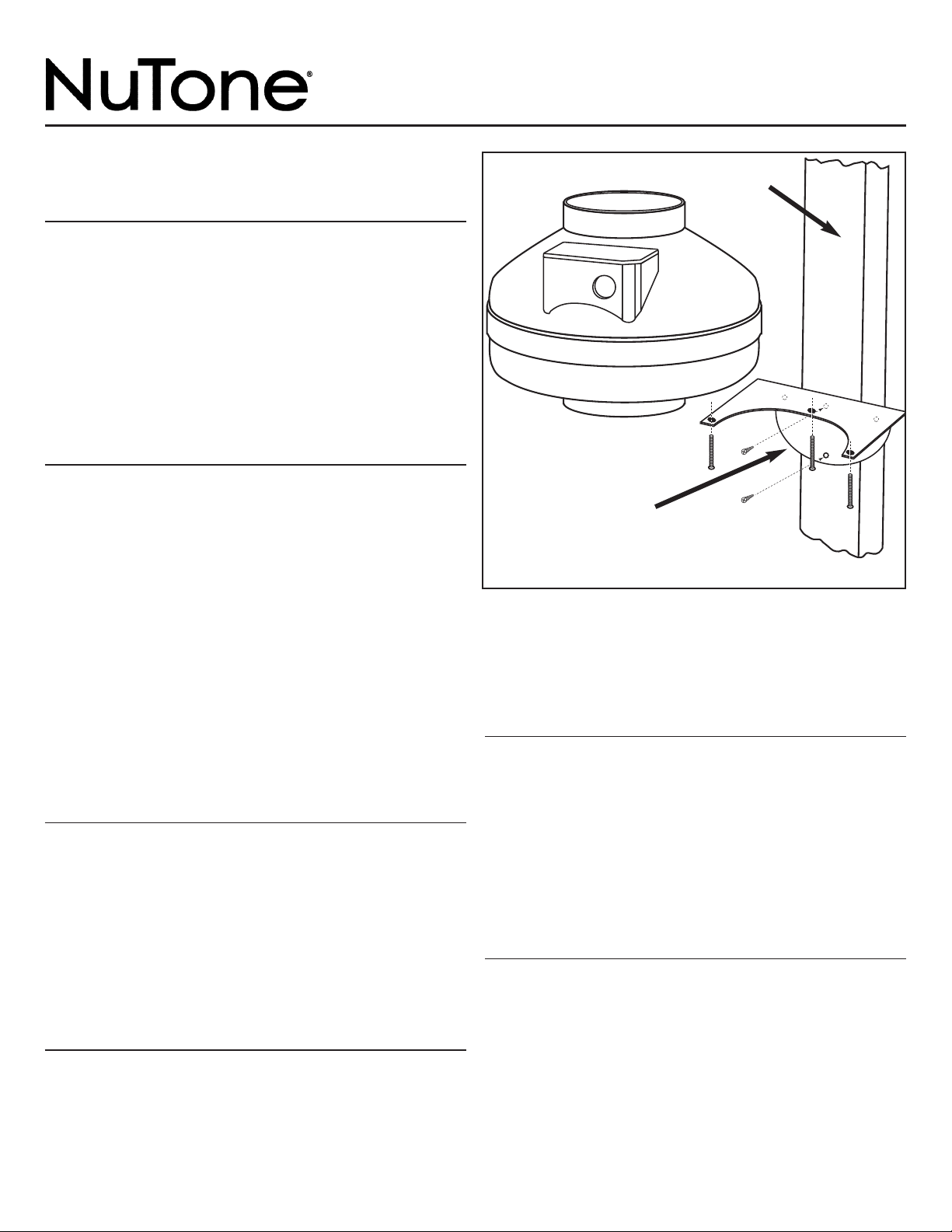
MOUNTING
1. Select a mounting site; Identify a mounting location that offers
accessibility with minimal duct run. Mount ventilator as far from
the inlet grille as practical to minimize noise.
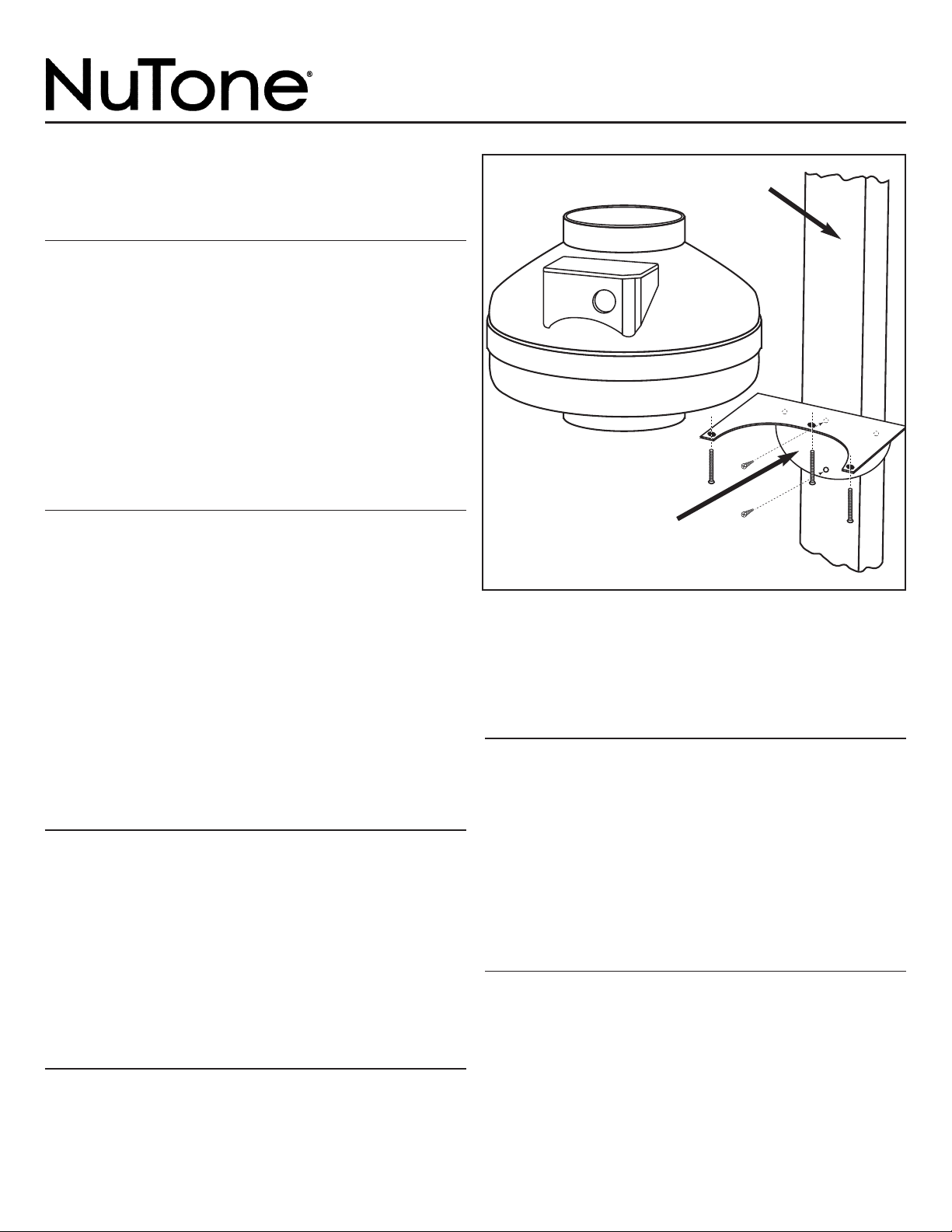
2. Attach fan mounting bracket to the support joist using the wood
screws provided (Refer to Figure 1). For best performance
vertical mounting is recommended, however any orientation is
acceptable.
3. Attach fan to the mounting bracket using the self threading
screws provided (Refer to Figure 1). To ease attachment
1
⁄16˝
pilot holes may be used for the mounting screws.
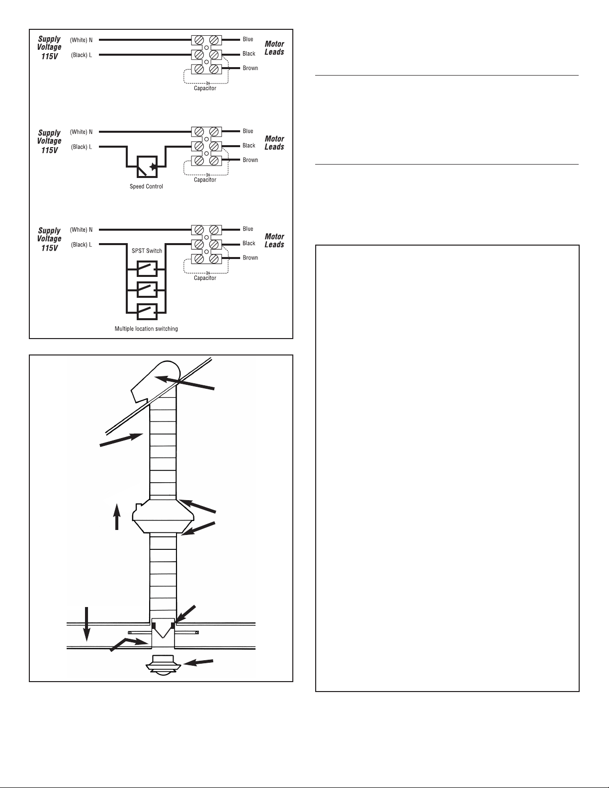
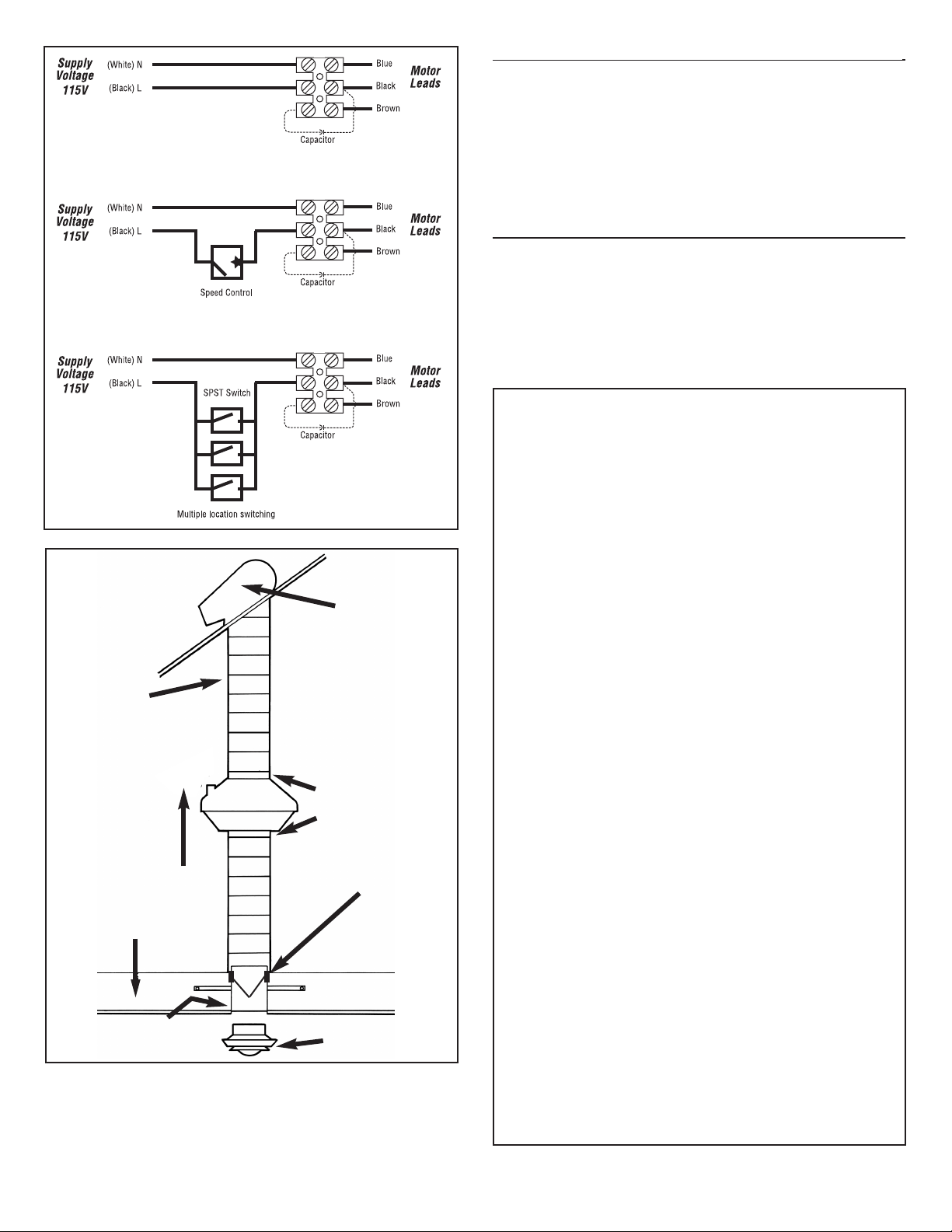
WIRING
1. Run 120v AC house power wiring through switch box to junction
box in ventilator housing.
2. Remove ventilator junction box cover.
3. Refer to Figure 2. Connect the house power wire (black) to the
terminal marked L. Connect the house neutral wire (white) to the
terminal marked N (see wiring diagram). The fan housing is fully
insulated and therefore no grounding is required.
4. Replace outlet box cover.
5. Connect house power wire to the wall switch.
NOTE: ALL WIRING MUST COMPLY WITH LOCAL
ELECTRICAL CODES.
DUCTING INSTALLATION
1. Refer to Figure 3. Attach duct to ventilator inlet and outlet using
clamps, fasteners and/or duct tape. Observe the following
recommendations for best results;
A. Always minimize duct lengths and turns.
B. When flexible ducting is used be sure that the duct is fully
stretched and free of kinks or sharp bends.
C. Use insulated ducting when passing through unconditioned spaces.
D. When insulated ducting is used clamp or tape the inner vinyl core to
the inlet and outlet of the fan and tape the vapor barrier surrounding the
duct insulation to the fan housing.
E. Always install a damper at the inlet grilles.
INSTALLATION INSTRUCTIONS
R
EAD & SAVE THESE INSTRUCTIONS!
In-Line Fans
MODELS: ILF120, ILF130, ILF250
FIGURE 1
MOUNTING BRACKET
JOIST OR STUD
FAN MOUNTING
2
INSTALLATION IN EXISTING
CONSTRUCTION
Installing in an existing building requires access to the attic or space
above the planned installation.
Carefully examine the installation area to be sure that;
1. Ducting can be installed.
2. Wiring can be run to the planned location.
3. No wiring or other obstructions might interfere with installation.
Install fan and ducting following the instructions in “Installation in a
New Construction Site”.
CARE AND MAINTENANCE
1. No regular maintenance is required.
FIGURE 2
WIRING
CONNECTIONS
BROAN-NUTONE ONE YEAR LIMITED WARRANTY
Broan-NuTone warrants to the original consumer purchaser of its
products that such products will be free from defects in materials or
workmanship for a period of one year from the date of original
purchase. THERE ARE NO OTHER WARRANTIES, EXPRESS OR
IMPLIED, INCLUDING, BUT NOT LIMITED TO, IMPLIED
WARRANTIES OF MERCHANTABILITY OR FITNESS FOR A
PARTICULAR PURPOSE.
During this one-year period, Broan-NuTone will, at its option, repair or
replace, without charge, any product or part which is found to be
defective under normal use and service.
THIS WARRANTY DOES NOT EXTEND TO FLUORESCENT LAMP
STARTERS, TUBES, HALOGEN AND INCANDESCENT BULBS,
FUSES, FILTERS, DUCTS, ROOF CAPS, WALL CAPS AND OTHER
ACCESSORIES FOR DUCTING. This warranty does not cover (a)
normal maintenance and service or (b) any products or parts which
have been subject to misuse, negligence, accident, improper
maintenance or repair (other than by Broan-NuTone), faulty installation
or installation contrary to recommended installation instructions.
The duration of any implied warranty is limited to the one-year period as
specified for the express warranty. Some states do not allow limitation
on how long an implied warranty lasts, so the above limitation may not
apply to you.
BROAN-NUTONE’S OBLIGATION TO REPAIR OR REPLACE, AT
BROAN-NUTONE’S OPTION, SHALL BE THE PURCHASER’S SOLE
AND EXCLUSIVE REMEDY UNDER THIS WARRANTY. BROAN-
NUTONE SHALL NOT BE LIABLE FOR INCIDENTAL,
CONSEQUENTIAL OR SPECIAL DAMAGES ARISING OUT OF OR IN
CONNECTION WITH PRODUCT USE OR PERFORMANCE. Some
states do not allow the exclusion or limitation of incidental or
consequential damages, so the above limitation or exclusion may not
apply to you.
This warranty gives you specific legal rights, and you may also have
other rights, which vary from state to state. This warranty supersedes all
prior warranties.
To qualify for warranty service, you must (a) notify Broan-NuTone at the
address or telephone number below, (b) give the model number and
part identification and (c) describe the nature of any defect in the
product or part. At the time of requesting warranty service, you must
present evidence of the original purchase date.
Broan-NuTone LLC, 926 W. State Street, Hartford, Wisconsin 53027
www.broan.com 800-558-1711
Broan-NuTone Canada, Inc., 1140 Tristar Drive, Mississauga, Ontario
L5T 1H9 www.broan.ca 877-896-1119
Rev. 12/15, Part No. 100933F
FIGURE 3
CEILING JOIST
DAMPERED SLEEVE
INLET GRILLE
AIR FLOW
ROOF OR
WALL CAP
DUCTING
INSTALLATION
SEAL DUCT
TO FAN WITH
DUCT TAPE
SEAL GAPS
AROUND SLEEVE
The ducting from this fan to the outside of the building has a strong
effect on the air flow, noise and energy use of the fan. Use the
shortest, straighest duct routing possible for best performance,
and avoid installing the fan with smaller ducts than recommended.
Insulation around the ducts can reduce energy loss and inhibit
mold growth. Fans installed with existing ducts may not achieve
their rated airflow.
KEEP DUCT
RUNS SHORT &
USE INSULATED
DUCT IN
UNCONDITIONED
SPACES
3
IMPORTANTES DIRECTIVES DE SÉCURITÉ
AVERTISSEMENT: POUR REDUIRE LES RESQUES D'INCENDIE,
DE CHOCS ÉLECTRIQUES OU DE BLESSURES, RESPECTER CE
QUI SUIT:
A. Utiliser cet appareil seulement pour les fins prévues par le fabricant.
Pour toute question, communiquer avec le fabricant.
B. Avant de faire l'entretien ou le nettoyage de l'appareil, couper le
courant au tableau de distribution et verrouiller ce dernier pour éviter
que le courant ne soit remis accidentellement.
Lorsque vous ne pouvez verrouiller l'interrupteur, placez un
avertissement clairement visible, par exemple une étiquette, sur le
tableau de distribution.
•Peuvent être utilisés avec une commande transistorisée de la vitesse.
ATTENTION: Pour ventilation générale seulement. Ne pas utiliser pour
évacuer des vapeurs ou des matières dangereuses ou explosives.
DIRECTIVES D'INSTALLATION
AVERTISSEMENT: POUR RÉDUIRE LES RISQUES D'INCENDIE,
DE CHOCS ÉLECTRIQUES OU DE BLESSURES, RESPECTER CE
QUI SUIT:
A. Les travaux d'installation et d'électricité doivent être confiés à des
personnes qualifiées, conformément auz normes et aux codes en
vigueur, notamment en ce qui concerne les normes de protection contre
les incendies.
B. Pour éviter les retours d'air, les appareils de chauffage doivent avoir
suffisamment d'air pour assurer une combustion et une évacuation
appropriée des gaz. Suivre les directives du fabricant de l'appareil de
chauffage ainsi que les normes de sécurité édictées par des organismes
comme la National Fire Protection Association (NFPA) I'American Society
for Heating, refrigeration and Air Conditioning Engineers (ASHRAE ou les
oranismes de réglementation locaux.
C. Lorsque bous percez les murs et plafonds, éviter d'endommager les fils
électriques et less autres canalisations.
D. Les venttilateurs dotés de tuyaux doivent toujours être raccordés à
I'extérieur.
E. NE JAMAIS placer un interrupteur à la portée d'une personne qui se
trouverait dans le bain ou la douche.
POUR DE MEILLEURS RÉSULTATS
Pour assurer un fonctionnement silencieux des ventilateurs qualifiés
ENERGY STAR®, chaque ventilateurs doit être installé en utilisant des
techniques d’atténuation du son appropriées pour l’installation. Pour les
applications de salles de bain et les application de ventilation générales,
au moins 8 pieds de conduits flexible isolé doivent être installées entre
les grilles d’évacuation et d’approvisionnement du ventilateur.
Lors de I'installation de cet appaeil dans une nouvelle résidence,
installer le ventilateur et le conduit pendant les premières étapes de la
construction. Les grilles d'aspiration ne doivent être mises en place
qu'après la finition des plafonds. L'installation de ce ventilateur dans
une résistance existante exige que bous puissiez accéder à un endroit
(grenier ou faux-plafond) situé au-dessus de la pièce à ventiler.
INSTALLATION DANS UNE NOUVELLE RÉSIDENCE
1. Choisir I'emplacement de l'appareil; trouver un emplacement facilement
accessible et où la longueur du conduit sera réduite au minimum.
Installer le ventilateur le plus loin possible de la grille d'aspiration dans le
but de réduire le bruit.
2. Fixer la bride de support du bentilateur à la solive au moyen des vis à
bois fournies (consulter l Figure 1). Pour de meilleurs résultats, on
recommande I'installation à la berticale, mais une autre orientation est
également acceptable.
3. Installer le ventilateur sur la bride de support au moyen des vis à
enfilement automatique fournies (consulter la Figure 1). Pour faciliter
I'installation, percer des trous de 1/16 po dans le ventilateur pour les vis.
CÂBLAGE
1. Faire passer un fil d'alimentation 120 V de la boîte de I'interrupteur à
la boîte électrique située dans le boîte du ventilateur.
2. Retirer le couvercle de la boîte électrique du ventilateur.
3. Consulter la Figure 2. Brancher le fil d'alimentation (noir) à la borne
portant la mention L. Brancher le fil d'alimentation neutre (blanc) à la
borne portant la mention N (voir le diagramme de câblage). Le boîter
du bentilateur est complètement isolé; il n'a donc pas à être mis à la
terre.
4. Replacer le couvercle de la boîte électrique.
5. Brancer les fils d'alimentation à I'interrupteur mural.
NOTE: LE CÂBLAGE DOIT ÊTRE CONFORME AUX CODES
ÉLECTRIQUES EN VIGUEUR.
INSTALLATION DU CONDUIT
1. Consulter la Figure 3. Raccordr le conduit à l'entrée et à la sortie du
ventilateur au moyen de collects, de brides ou de ruban adhésif pour
conduit. Pour de meilleurs résultats, suivre les recommandations ci-
dessous:
A. Réduire au minimum la longueur du conduit et le nombre de coudes.
B. Lors de I'utilisation de conduit flexible, s'assurer que le conduit est
complètement étendu et qu'il n'y a pas de bosses ni de coudes.
C. Utiliser un conduit isolépour traverser les endroits non chauffés.
D. Lors de I'utilisation d'un conduit isolé, fixer ou coller la gaine interne de
vinyle à l'intrée et à la sortie du bentilateu, puis coller le coupe vapeur
entourant II'isolant du conduit au boître du registre au niveau de la grille
d'aspiration.
E.Installer toujours in registre au niveau de la grille d'apiration.
DIRECTIVES D'INSTALLATION
L
IRE ET CONSERVER CES DIRECTIVES
Ventilateurs verticaux
MODÈLES: ILF120, ILF130, ILF250
FIGURE 1
BRIDE DE SUPPORT
SOLIVE OU MONTANT
INSTALLATION DU VENTILATEUR
4
INSTALLATION DANS UNE RÉSIDENCE EXISTANTE
L'installation dans une résidence existante exige quevous puessies
accéder au grenier ou à l'endroit situé au dessus de I'emplacement prévu
pour la grille d'aspiration.
Examiner avec soin I'emplacement pour vous assurer:
1. Que le conduit peut être installé
2. Que les fils peuvent être acheminés au ventilateur
3. Qu'aucun fil ou autre obstacle ne nuira à la mise en place de
l'appareil. Installer le ventilateur et l conduit conformément aux directives
de la section Installation dans une nouvelle résidence
.
ENTRETIEN ET MAINTENANCE
1. Aucune maintenance régulière n'est nécessaire.
Rev. 12/15, Part No. 100933F
GARANTIE LIMITÉE D’UN AN BROAN-NUTONE
Broan-NuTone garantit à l’acheteur original que les produits vendus en
vertu de la présente sont libres de tout vice de matériau ou de
fabrication pour une période d’un an à compter de la date d’achat
originale. CETTE GARANTIE NE COMPORTE AUCUNE AUTRE
GARANTIE, EXPRESSE OU TACITE, Y COMPRIS, MAIS SANS S’Y
LIMITER, LES GARANTIES TACITES DE VALEUR MARCHANDE OU
D’ADAPTATION À UN USAGE PARTICULIER.
Durant cette période d’un an, Broan-NuTone réparera ou remplacera
gratuitement, à sa discrétion, tout produit ou toute pièce jugés
défectueux dans des conditions normales d’utilisation.
CETTE GARANTIE NE S’APPLIQUE PAS AUX TUBES
FLUORESCENTS ET AUX DÉMARREURS, NI AUX AMPOULES
HALOGÈNES OU INCANDESCENTES, FUSIBLES, FILTRES,
CONDUITS, CAPUCHONS DE TOIT, CAPUCHONS MURAUX ET
AUTRES ACCESSOIRES POUR CONDUITS. Cette garantie ne couvre
pas (a) les frais d’entretien ou de service normaux ni (b) tout produit ou
toute pièce soumis à un abus, une négligence, un accident, un entretien
ou une réparation inadéquats (autres que ceux effectués par Broan-
NuTone), une mauvaise installation ou une installation contraire aux
instructions recommandées.
La durée de toute garantie tacite est limitée à la période d’un an
stipulée pour la garantie expresse. Certains territoires ou provinces
interdisant de limiter la durée d’une garantie tacite, la limitation ci-
dessus peut ne pas s’appliquer à votre situation.
L’OBLIGATION POUR BROAN-NUTONE DE RÉPARER OU DE
REMPLACER LE PRODUIT, À SA DISCRÉTION, CONSTITUE LE
SEUL RECOURS DE L’ACHETEUR EN VERTU DE LA PRÉSENTE
GARANTIE. BROAN-NUTONE NE PEUT ÊTRE TENUE
RESPONSABLE DES DOMMAGES INDIRECTS OU CONSÉCUTIFS
NI DES DOMMAGES-INTÉRÊTS PARTICULIERS DÉCOULANT DE
L’UTILISATION OU DU RENDEMENT DU PRODUIT. Certains
territoires ou provinces ne permettant pas la limitation ou l’exclusion des
dommages indirects ou consécutifs, la limitation ci-dessus peut ne pas
s’appliquer à votre situation.
La présente garantie vous confère des droits spécifiques reconnus par
la loi. D’autres droits pourraient également vous être accordés selon la
législation locale en vigueur. La présente garantie remplace toutes les
autres garanties précédentes.
Pour vous prévaloir de cette garantie, vous devez (a) aviser Broan-
NuTone à l’adresse ou au numéro de téléphone indiqués ci-dessous,
(b) donner le numéro de modèle du produit et le numéro d’identification
de la pièce et (c) décrire la nature de la défectuosité du produit ou de la
pièce. Lors de votre demande de garantie, vous devez présenter une
preuve de la date d’achat originale.
Broan-NuTone LLC, 926 W. State Street, Hartford, Wisconsin 53027
www.broan.com 800-558-1711
Broan-NuTone Canada, Inc., 1140 Tristar Drive, Mississauga, Ontario
L5T 1H9 www.broan.ca 877-896-1119
FIGURE 3
Solive du plafond
Manchon avec registre
Grille d'aspiration
Direction de l'air
Évent de toit
ou mural
INSTALLATION
DU CONDUIT
Garder les
conduit courtes
et utilisez
conduit isolé
dans des
espaces
inconditionné.
Sceller conduit
au ventilateur
avec du ruban
adhésif.
Sceller les espaces
autour des manches.
Les conduits allant de ce ventilateur jusqu’à l’extérieur de l’habitation
ont une grande influence sur le débit d’air, le bruit du ventilateur et sa
consommation d’énergie. Pour obtenir le meilleur rendement, utilisez
les conduits les plus courts et les plus droits que possible et évitez
d’utiliser des conduits plus petits que ceux recommandés. L’isolation
des con-duits peut contribuer à réduire les pertes d’énergie et éviter la
prolifération de moisissures. Les ventilateurs installés sur d’anciens
conduits pourraient ne pas produire leur débit d’air nominal.