
1
Owner’s Manual
SmartRack
™
Accessories
Model: SRCABLELADDER
1 – Introduction 2
1-2 Tools Required 2
3 – Installation 3
3-2 Ladder Modification (Optional) 4
3-4 Installation Across Aisle 5
3-6 Ground Connection 7
Français 17
1-1 Parts List 2
2 – Important Safety Instructions 2
3-1 Planning 3
3-3 Ladder Assembly 4
3-5 Installation Within Row 6
Español 9
4 – Storage and Service 8
5 – Warranty and Warranty Registration 8
1111 W. 35th Street, Chicago, IL 60609 USA
www.tripplite.com/support
Copyright © 2011 Tripp Lite. All trademarks are the sole property of their respective owners.
WARRANTY
REGISTRATION:
register online today for a
chance to win a FREE Tripp Lite
product—www.tripplite.com/warranty
201105211 93-2973.indb 1 5/23/2011 12:56:45 PM

2
1 – Introduction
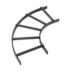
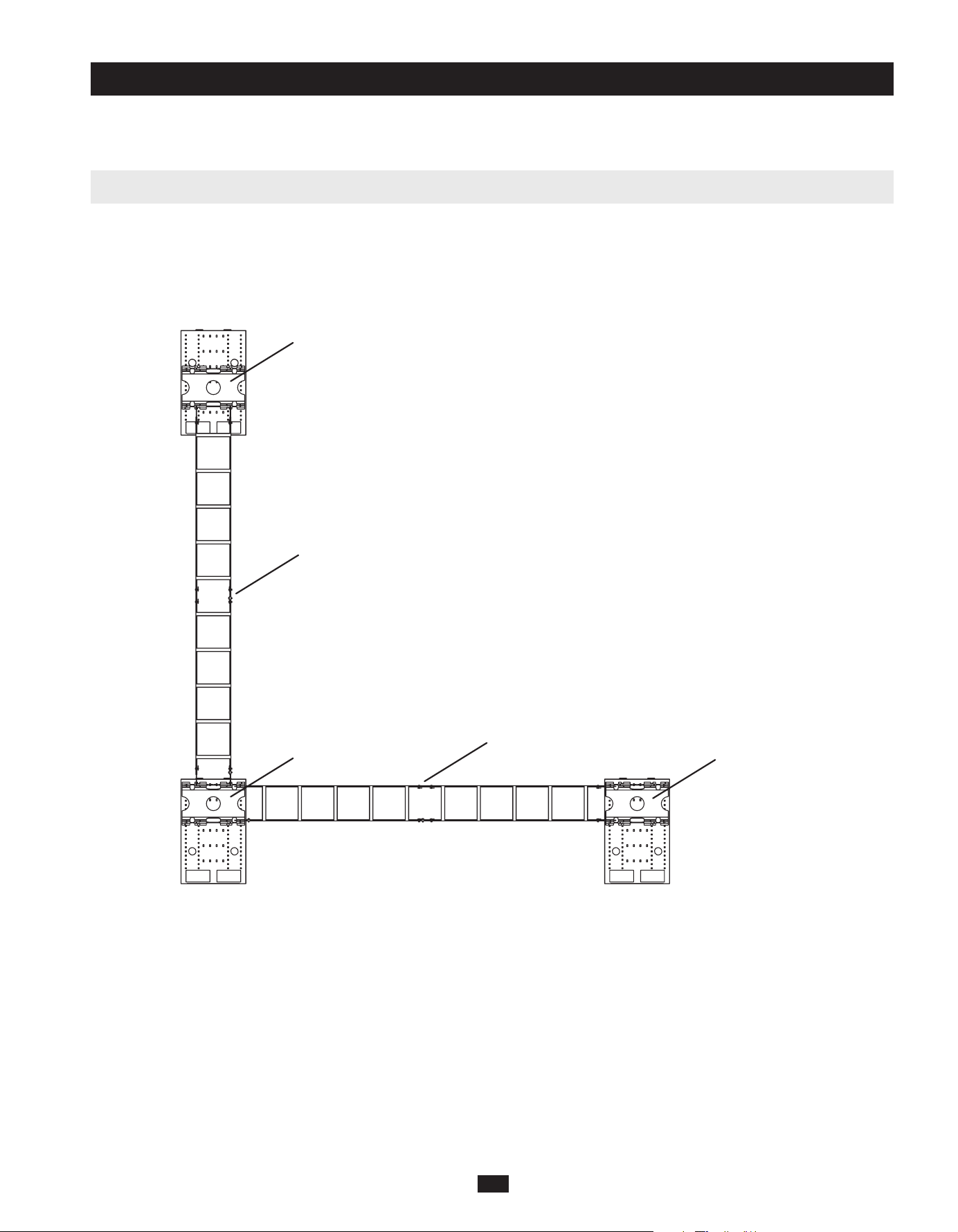
SRCABLELADDER provides roof-mounted cable routing for Tripp Lite’s SmartRack Enclosures, allowing cable bundles to span aisles and/or
spaces between enclosures in the same row. Note: Standard installation of SRCABLELADDER requires Tripp Lite’s SRCABLETRAY accessory,
sold separately.
SAVE THESE INSTRUCTIONS
This manual contains instructions and warnings that must be followed during the installation and operation of the product described in this
manual. Read all instructions and warnings thoroughly before attempting installation. Failure to comply may invalidate the warranty and
cause property damage and/or personal injury.
• Installinacontrolledindoorenvironment,awayfrommoisture,temperatureextremes,ammableliquidsandgasses,conductive
contaminants, dust and direct sunlight.
• Providesuitablegroundinginaccordancewithallapplicableelectricalwiringregulations.
• Donotattempttoclimborwalkacrossanypartoftheladder.
• Whenusingtoolstocutordrillmetal,useeyeprotectionandfollowallothersafetyprecautionsrecommendedbythetoolmanufacturerand
requiredbyapplicablesafetyregulations.
• Usecautionandwearsafetygloveswhenhandlingmetalpartsthathavebeencuttolength.Sharpedgescancausepersonalinjuryand
property damage.
• Useofthisequipmentinlifesupportapplicationswherefailureofthisequipmentcanreasonablybeexpectedtocausethefailureofthelife
supportequipmentortosignicantlyaffectitssafetyoreffectivenessisnotrecommended.Donotusethisequipmentinthepresenceofa
ammableanestheticmixturewithair,oxygenornitrousoxide.
• 13mmWrenchorCrescentWrench
• TapeMeasure
• Hacksaw(optional)
• Drillwith3/8-inchBit(optional)
LadderSections(2)
AssemblyBrackets(4)
ClevisPins(8)
CotterPins(8)
GroundBrackets(2)
M6Hex-HeadBolts(2)
24-inchGroundCables(3)
M6LockWashers(4)
M6HexNuts(2)
LadderClamp(4)
M10x60mmCarriageBolts(2)
M10LockWashers(2)
M10HexNuts(2)
Ifanypartsaremissing,visitwww.tripplite.com/support.
1-1 Parts List
2 – Important Safety Instructions
1-2 Tools Required
A A D
B E H
C
J K L M
F I
B
C
D
E
F
G
H
I
J
K
L
M
G
201105211 93-2973.indb 2 5/23/2011 12:56:45 PM
3
SRCABLELADDER can provide enclosure-to-enclosure cable routing across an aisle or within a single row. You can combine multiple
SRCABLELADDERandSRCABLETRAYaccessoriestomeetthecableroutingneedsofalmostanycongurationofSmartRackEnclosures,
butplanningandmeasurementarerequiredtoensureasecuret.TrippLiterecommendsthatyoureadtheentiremanualinadvancetogaina
clear understanding of the installation process and accessory positioning.
Sample Cable Routing Configuration (Top View)
UseatapemeasuretodeterminethedistancethatSRCABLELADDERwillbridge.(Preassemblingtheladdersectionswillallowyoutoobserve
theirattachmentpointsinplaceforamoreaccuratemeasurement.)
ThestandardlengthofSRCABLELADDERis10feet.Ifthestandardlengthandthedistancebetweenattachmentpointsdiffer,adjustingthe
positionoftheSRCABLETRAYaccessorieswillallowyoutochangethedistancebetweenattachmentpoints.Ifnecessary,youcanuseasingle
laddersectioninsteadoftwosections,reducingtheoverallladderlengthtoapproximately5feet.Inaddition,theassemblybracketsattheends
of the ladder sections will allow minor adjustments if you install them without pins, and you can add a few inches to the length of the ladder
byusingthealternatepinholesforassembly.IftheavailableadjustmentswillnotaccommodatetheSRCABLELADDERaccessory,youmust
cut one of the ladder sections. See Section 3-2 Ladder Modicationforinstructions.IftheSRCABLELADDERaccessorywilltwithout
modication,proceedtoSection 3-3 Ladder Assembly.
Note: Prior to installation, you must install the SRCABLETRAY accessory (sold separately) on each enclosure that will be linked by the
SRCABLELADDER accessory. For ordering information, visit www.tripplite.com.
3-1 Planning
3 – Installation
SRCABLETRAY
SRCABLETRAY
SRCABLETRAY
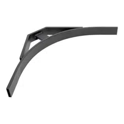
SRCABLELADDER installed
between enclosures across an aisle.
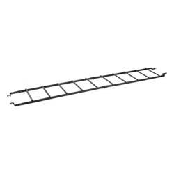
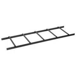
SRCABLELADDER installed
between enclosures within a row.
201105211 93-2973.indb 3 5/23/2011 12:56:45 PM
4
3-2 Ladder Modification (Optional)
Warning: When using tools to cut or drill metal, use eye protection and follow all other safety precautions recommended by the tool
manufacturer and required by applicable safety regulations. Use caution and wear safety gloves when handling metal parts that have
been cut to length. Sharp edges can cause personal injury and property damage.
Note: Do not modify the SRCABLELADDER accessory unless you have followed the instructions in Section 3-1 Planning and determined that
modication is required. If modication is not required, proceed to Section 3-3 Ladder Assembly.
Measureandmarkthecableladdersectionthatwillbecut.
Useahacksaworothermetal-cuttingtooltocutthroughtheladdersection.Makesureyourcutisperpendiculartothelengthoftheladder
and use a metal-cutting tool that will not bend or crush the ladder section.
(Optional)Aftercutting,useadrillwitha3/8-inchbittodrillnewpinholesinendoftheladdersection.Comparethemodiedendofthe
laddersectionwiththeunmodiedendtodeterminewhereholesshouldbedrilled.Makesurethattheholelocationmatchesyourplanning
and measurements. You may omit this step, but drilling the pin holes and installing the pins will make the SRCABLELADDER accessory
more stable.
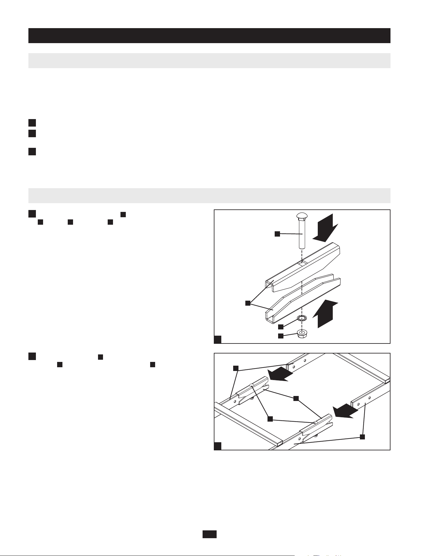
3-3 Ladder Assembly
Assemble the two ladder clamps
A
withtheM10carriagebolts
B
, washers
C
andhexnuts
D
as seen in the diagram. For now,
only tighten the nuts far enough to keep the clamps assembled
together.
Join the ladder sections
E
by inserting each side into the ladder
clamps
A
until they are stopped by the bolts
B
.Whenthesections
are joined, you can now secure the clamp by fully tightening the
nuts.
3 – Installation (continued)
1
2
3
1
2
1
2
A
B
C
D
E
X2
A
E
B
201105211 93-2973.indb 4 5/23/2011 12:56:45 PM

5
Note: Follow the instructions in this section only if the SRCABLELADDER accessory will be installed across an aisle. If the SRCABLELADDER
accessory will be installed within a row of enclosures, follow the instructions in Section 3-5 Installation Within Row instead.
3-4 Installation Across Aisle
Insertfourassemblybrackets
A
into the ends of the ladder. The
hookedendsofthebracketsshouldbeexposed.Whentheladderis
oriented so that the ladder’s rungs are above the ladder’s side rails,
the hooked ends of the brackets should point down, as shown in
the drawing.
Align the pin holes in the ladder sections with the pin holes
in the assembly brackets and insert clevis pins
B
into the pin
holes(4total).Thisstepmaybeomittedtoprovideadditional
installationexibility,butinstallingthepinswillmakethe
SRCABLELADDER accessory more stable. Warning: If you
choose not to install the clevis pins, make sure at least 25% of
the length of each assembly bracket is inside the ladder.
After inserting the clevis pins, insert a cotter pin
C
through the
holeattheendofeachclevispin.(Thestraightsectionofthe
cotterpingoesthroughthehole.)
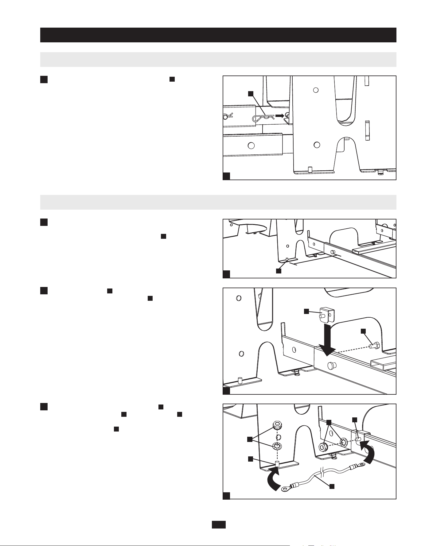
Usinganassistant,lifttheSRCABLELADDERaccessory
(rungsupward)andinserttheexposedhookendsofthe
assembly brackets
D
into the corresponding slots
E
in the
SRCABLETRAY accessories installed at the top of each
enclosure.Thehooksshouldttheslotssecurelybyslidingdown
to engage the edge of the slot. Note: There are two levels of slots.
Use the slots that match your application best.
3 – Installation (continued)
2
3
B
B
1
1
2
3
4
4
A
C
D
E
201105211 93-2973.indb 5 5/23/2011 12:56:46 PM

6
Note: Follow the instructions in this section only if the SRCABLELADDER accessory will be installed within a row of enclosures. If the
SRCABLELADDER accessory will be installed across an aisle, follow the instructions in Section 3-4 Installation Across Aisle instead.
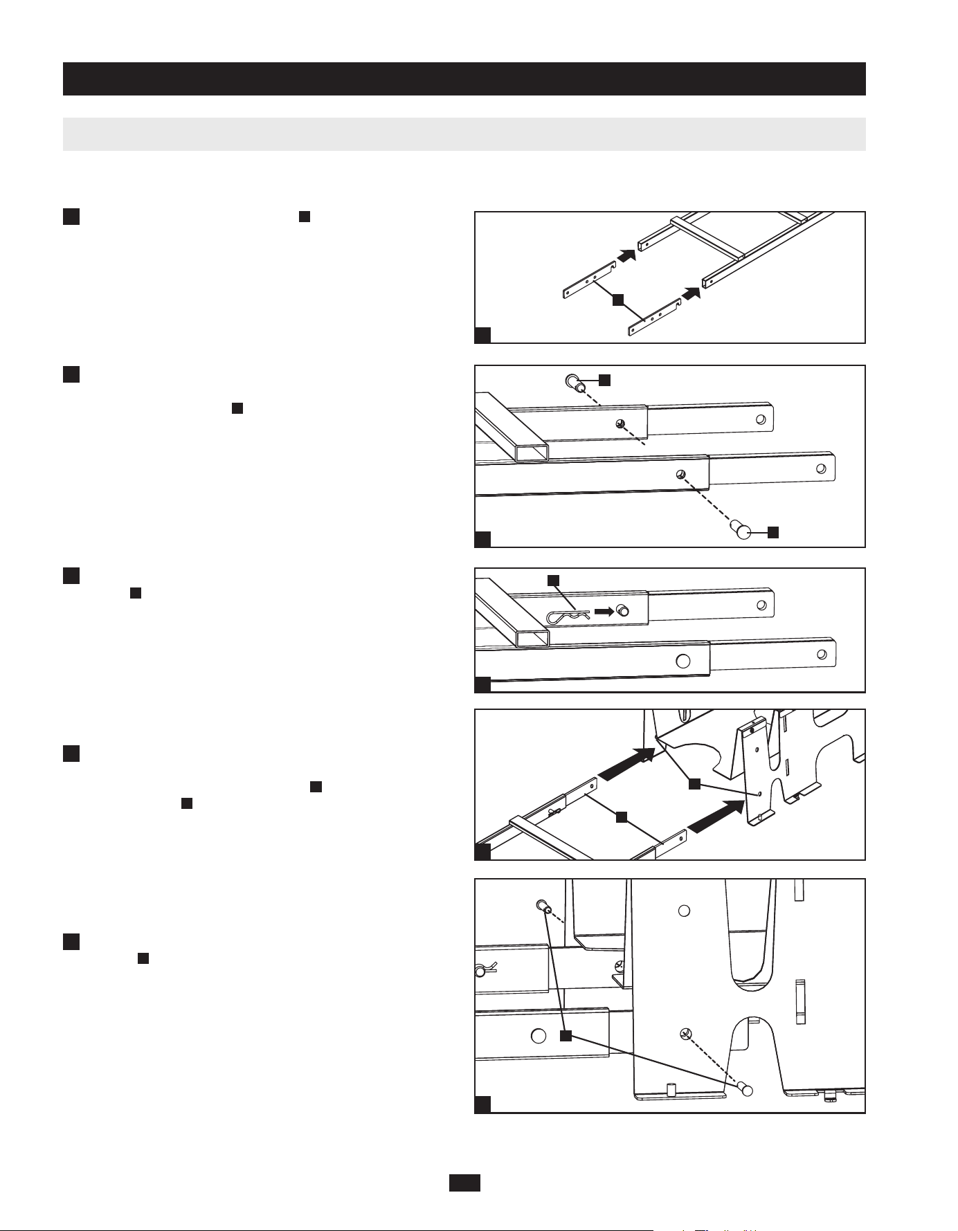
3-5 Installation Within Row
Insertfourassemblybrackets
A
in the open ends of the ladder,
hookedendrst.Whentheladderisorientedsothattheladder’s
rungs are above the ladder’s side rails, the hooked ends of the
brackets should point down, as shown in the drawing.
Align the pin holes in the ladder sections with the pin holes
in the assembly brackets and insert clevis pins
B
into the pin
holes(4total).Thisstepmaybeomittedtoprovideadditional
installationexibility,butinstallingthepinswillmakethe
SRCABLELADDER accessory more stable. Warning: If you
choose not to install the clevis pins, make sure at least 25% of
the length of each assembly bracket is inside the ladder.
After inserting the clevis pins, insert a cotter pin
C
through the
holeattheendofeachclevispin.(Thestraightsectionofthe
cotterpingoesthroughthehole.)
Usinganassistant,lifttheSRCABLELADDERaccessory(rungs
upward)andaligntheholesattheendsoftheassemblybrackets
D
with the corresponding holes
E
in the SRCABLETRAY
accessories installed at the top of each enclosure. Note: There are
two levels of holes. Use the holes that match your application best.
Align the pin holes and insert clevis pins
F
into each of the pin
holes(4total).
3 – Installation (continued)
2
3
B
B
C
1
1
2
3
4
5
5
4
D
E
F
A
201105211 93-2973.indb 6 5/23/2011 12:56:47 PM
7
3-5 Installation Within Row (continued)
3-6 Ground Connection
After installing the SRCABLELADDER accessory, determine
where to place ground brackets by noting the distance between
one end of the ladder and the grounding post
A
at the corner of the
nearest SRCABLETRAY accessory.
Placeagroundbracket
B
near the end of the SRCABLELADDER
accessory’sleganduseahex-headbolt
C
to secure it.
Usetheincludedhexnutsandlockwashers
G
to connect one end
of the included ground cable
H
to a grounding post
I
at the corner
of the nearest SRCABLETRAY accessory and connect the other
end to the grounding post
J
of the ground bracket attached to the
SRCABLELADDERaccessory.Repeatsteps1to3fortheother
end of the SRCABLELADDER accessory.
After inserting the clevis pins, insert a cotter pin
G
through the
holeattheendofeachclevispin.(Thestraightsectionofthe
cotterpingoesthroughthehole.)
3 – Installation (continued)
1
6
2
3
G
6
A
1
2
3
B
C
G
G
H
I
J
201105211 93-2973.indb 7 5/23/2011 12:56:48 PM

8
4 – Storage and Service
5 – Warranty and Warranty Registration
1111 W. 35th Street, Chicago, IL 60609 USA
www.tripplite.com/support
Storage
Theunitmustbestoredinaclean,secureenvironmentwithatemperaturelessthan40°C(104°F)andarelativehumiditylessthan90%
(non-condensing).Storetheunitinitsoriginalshippingcontainerifpossible.
Service
YourTrippLiteproductiscoveredbythewarrantydescribedinthismanual.AvarietyofExtendedWarrantyandOn-SiteServicePrograms
are also available from Tripp Lite. For more information on service, visit www.tripplite.com/support. Before returning your product for service,
follow these steps:
1.Reviewtheinstallationandoperationproceduresinthismanualtoinsurethattheserviceproblemdoesnotoriginatefromamisreadingofthe
instructions.
2.Iftheproblemcontinues,donotcontactorreturntheproducttothedealer.Instead,visitwww.tripplite.com/support.
3.Iftheproblemrequiresservice,visitwww.tripplite.com/supportandclicktheProductReturnslink.FromhereyoucanrequestaReturned
MaterialAuthorization(RMA)number,whichisrequiredforservice.Thissimpleon-lineformwillaskforyourunit’smodelandserial
numbers,alongwithothergeneralpurchaserinformation.TheRMAnumber,alongwithshippinginstructionswillbeemailedtoyou.Any
damages(direct,indirect,specialorconsequential)totheproductincurredduringshipmenttoTrippLiteoranauthorizedTrippLiteservice
centerisnotcoveredunderwarranty.ProductsshippedtoTrippLiteoranauthorizedTrippLiteservicecentermusthavetransportation
chargesprepaid.MarktheRMAnumberontheoutsideofthepackage.Iftheproductiswithinitswarrantyperiod,encloseacopyofyour
salesreceipt.ReturntheproductforserviceusinganinsuredcarriertotheaddressgiventoyouwhenyourequesttheRMA.
Limited Warranty
Seller warrants this product, if used in accordance with all applicable instructions, to be free from original defects in material and workmanship
foraperiodof5yearsfromthedateofinitialpurchase.Iftheproductshouldprovedefectiveinmaterialorworkmanshipwithinthatperiod,
Seller will repair or replace the product, in its sole discretion.
THISWARRANTYDOESNOTAPPLYTONORMALWEARORTODAMAGERESULTINGFROMACCIDENT,MISUSE,ABUSE
ORNEGLECT.SELLERMAKESNOEXPRESSWARRANTIESOTHERTHANTHEWARRANTYEXPRESSLYSETFORTHHEREIN.
EXCEPTTOTHEEXTENTPROHIBITEDBYAPPLICABLELAW,ALLIMPLIEDWARRANTIES,INCLUDINGALLWARRANTIESOF
MERCHANTABILITYORFITNESS,ARELIMITEDINDURATIONTOTHEWARRANTYPERIODSETFORTHABOVE;ANDTHIS
WARRANTYEXPRESSLYEXCLUDESALLINCIDENTALANDCONSEQUENTIALDAMAGES.(Somestatesdonotallowlimitations
onhowlonganimpliedwarrantylasts,andsomestatesdonotallowtheexclusionorlimitationofincidentalorconsequentialdamages,sothe
abovelimitationsorexclusionsmaynotapplytoyou.ThisWarrantygivesyouspeciclegalrights,andyoumayhaveotherrightswhichvary
fromjurisdictiontojurisdiction.)
TrippLite;1111W.35thStreet;ChicagoIL60609;USA
WARNING:Theindividualusershouldtakecaretodeterminepriortousewhetherthisdeviceissuitable,adequateorsafefortheuseintended.
Sinceindividualapplicationsaresubjecttogreatvariation,themanufacturermakesnorepresentationorwarrantyastothesuitabilityortness
ofthesedevicesforanyspecicapplication.
Warranty Registration
Visitwww.tripplite.com/warrantytodaytoregisterthewarrantyforyournewTrippLiteproduct.You’llbeautomaticallyenteredintoadrawing
for a chance to win a FREE Tripp Lite product!*
*Nopurchasenecessary.Voidwhereprohibited.Somerestrictionsapply.Seewebsitefordetails.
TrippLitehasapolicyofcontinuousimprovement.Specicationsaresubjecttochangewithoutnotice.
201105211 • 932973-EN
201105211 93-2973.indb 8 5/23/2011 12:56:48 PM

9
Manual del propietario
Accesorios SmartRack
™
Modelo: SRCABLELADDER
1 – Introducción 10
1-2 Herramientas requeridas 10
3 – Instalación 11
3-2 Modificación de la escalera (Opcional) 12
3-4 Instalación en pasillo 13
3-6 Conexión a tierra 15
1-1 Lista de piezas 10
2 – Instrucciones de seguridad importantes 10
3-1 Planificación 11
3-3 Ensamblado de la escalera 12
3-5 Instalación en una fila 14
4 – Almacenamiento y servicio 16
5 – Garantía 16
1111 W. 35th Street, Chicago, IL 60609 USA
www.tripplite.com/support
Copyright © 2011 Tripp Lite. Todas las otras marcas registradas son propiedad de sus respectivos dueños.
Français 17
English 1
201105211 93-2973.indb 9 5/23/2011 12:56:49 PM

10
1 – Introducción
SRCABLELADDERofreceenrutamientodecableparamontareneltechopararacksSmartRackdeTrippLite,quepermitequelosmanojos
decablesseexpandanenpasillosy/oespaciosentreracksdelamismala. Nota: La instalación estándar de SRCABLELADDER requiere el
accesorio SRCABLETRAY de Tripp Lite, que se vende por separado.
GUARDE ESTAS INSTRUCCIONES
Estemanualcontieneinstruccionesyadvertenciasquedebenseguirsedurantelainstalaciónyoperacióndelproductodescritoenestemanual.
Leatodaslasinstruccionesyadvertenciasantesdelainstalación.Elincumplimientoinvalidarálagarantía,pudiendocausarseriosdañosala
propiedad y/o lesiones personales.
• Instaleenunambienteinteriorcontrolado,lejosdelahumedad,temperaturasextremas,líquidosygasesinamables,contaminantes
conductores,polvoyluzsolardirecta.
• Proporcioneunaconexiónatierraadecuada,segúnlasreglamentacionesdecableadoeléctricoaplicables.
• Nointentetreparocaminarporningunapartedelaescalera.
• Cuandoutiliceherramientasparacortarotaladrarmetal,utiliceprotecciónparalosojosysigatodaslasprecaucionesdeseguridad
recomendadasporelfabricantedelasherramientasyrequeridasporlasreglamentacionesdeseguridadaplicables.
• Tengaprecauciónyutiliceguantesdeseguridadcuandomanipulepiezasmetálicasquesehancortadoenlongitud.Losbordesalados
puedenprovocarlesionespersonalesydañosenlapropiedad.
• Noserecomiendausaresteequipoenaplicacionesdemantenimientoarticialdelavida,dondesepuedeesperarrazonablementequesu
fallacauselafalladelequipodemantenimientodelavidaoqueafectedemaneraimportantesuseguridadoeciencia.Nouseesteequipo
enpresenciademezclasanestésicasinamablesconaire,oxígenouóxidonitroso.
• Llavede13mmollaveenformadecuña
• Cinta para medir
• Sierradearco(opcional)
• Taladroconmechade3/8pulgadas(opcional)
Seccionesdelaescalera(2)
Soportesdeensamblado(4)
Pasadoresdehorquilla(8)
Pasadoresdechaveta(8)
Soportesparaelsuelo(2)
PernosdecabezahexagonalM6(2)
Cablesdeconexiónatierrade24pulgadas(3)
ArandelasdesujeciónM6(4)
TuercashexagonalesM6(2)
Fijadordelaescalera(4)
PernosdetransporteM10x60mm(2)
ArandelasdesujeciónM10(2)
TuercashexagonalesM10(2)
Silefaltaalgunapieza,visitewww.tripplite.com/support.
1-1 Lista de piezas
2 – Instrucciones de seguridad importantes
1-2 Herramientas requeridas
A A D
B E H
C
J K L M
F I
B
C
D
E
F
G
H
I
J
K
L
M
G
201105211 93-2973.indb 10 5/23/2011 12:56:49 PM

11
SRCABLELADDERpuedeofrecerenrutamientodecablesderackarackenunpasilloodentrodeunasolala.Puedecombinarvarios
accesoriosSRCABLELADDERySRCABLETRAYparasatisfacerlasnecesidadesdeenrutamientodecablesdelamayoríadelas
conguracionesderacksSmartRack,peroserequierenplanicaciónymediciónparagarantizarunajusteseguro.TrippLiterecomiendaquelea
todoelmanualpreviamenteparaobtenerunclaroentendimientodelprocesodeinstalaciónydelposicionamientodelaccesorio.
Configuración de enrutamiento de cable de ejemplo (Vista superior)
UtiliceunacintaparamedirparadeterminarladistanciaqueocuparáelSRCABLELADDER.(Elensambladopreviodelasseccionesdela
escalerapermitiráobservarlospuntosdeuniónparalograrunamedidamásprecisa).
LalongitudestándardelSRCABLELADDEResde10pies.Siexistediferenciaentrelalongitudestándaryladistanciaentrelospuntosde
unión,elajustedelaposicióndelosaccesoriosSRCABLETRAYpermitirácambiarladistanciaentrelospuntosdeunión.Siesnecesario,
puedeutilizarunasolaseccióndeescaleraenlugardedos,reduciendoasílalongitudtotaldelaescaleraenaproximadamente5pies.Además,
lossoportesdeensambladoenlosextremosdelasseccionesdelaescalerapermitiránajustesmenoressilosinstalasinpasadores,ypuede
agregaralgunaspulgadasalalongituddelaescaleramediantelosoriciosdepasadoresalternativosparaensamblado.Silosajustesdisponibles
noacomodanelaccesorioSRCABLELADDER,deberácortarunadelasseccionesdelaescalera.ConsultelaSección 3-2 Modicación de la
escaleraparaobtenerinstrucciones.SielaccesorioSRCABLELADDERencajasinmodicaciones,continúeconlaSección 3-3 Ensamblado
de la escalera.
Nota: Antes de la instalación, debe instalar el accesorio SRCABLETRAY (se vende por separado) en cada rack que se vinculará por medio del
accesorio SRCABLELADDER. Para obtener información de pedidos, visite www.tripplite.com.
3-1 Planificación
3 – Installation
SRCABLETRAY
SRCABLETRAY
SRCABLETRAY
SRCABLELADDER instalado
entre racks en un pasillo.
SRCABLELADDER instalado
entre racks dentro de una fila.
201105211 93-2973.indb 11 5/23/2011 12:56:49 PM

12
3-2 Modificación de la escalera (Opcional)
Advertencia: Cuando utilice herramientas para cortar o taladrar metal, utilice protección para los ojos y siga todas las precauciones de
seguridad recomendadas por el fabricante de las herramientas y requeridas por las reglamentaciones de seguridad aplicables. Tenga
precaución y utilice guantes de seguridad cuando manipule piezas metálicas que se han cortado en longitud. Los bordes alados pueden
provocar lesiones personales y daños en la propiedad.
Nota: No modique el accesorio SRCABLELADDER a menos que haya seguido las instrucciones de la Sección 3-1 Planicación y haya
determinado que la modicación es necesaria. Si no se requiere modicación, continúe con la Sección 3-3 Ensamblado de la escalera.
Midaymarquelaseccióndelaescaleradelcablequesecortará.
Utiliceunasierradearcouotraherramientaparacortarmetalesparacortarlaseccióndelaescalera.Asegúresedequeelcortesea
perpendicularalalongituddelaescalerayutiliceunaherramientaparacortarmetalesquenodobleorompalaseccióndelaescalera.
(Opcional)Despuésdecortar,utiliceuntaladroconunamechade3/8pulgadasparataladrarnuevosoriciosdepasadoresenelextremode
laseccióndelaescalera.Compareelextremomodicadodelaseccióndelaescaleraconelextremosinmodicarparadeterminardóndese
debentaladrarlosoricios.Asegúresedequelaubicacióndeloriciocoincidaconlaplanicaciónylasmedidas.Puedeomitirestepaso,
perositaladralosoriciosdelospasadoreseinstalalospasadoreslograráqueelaccesorioSRCABLELADDERseamásestable.
3-3 Ensamblado de la escalera
Ensamblelosdosjadoresdelaescalera
A
con los pernos de
transporte
B
, arandelas
C
ytuercashexagonales
D
como se
muestraeneldiagrama.Porahora,ajustesólolastuercaslo
sucientecomoparaquelosjadoresquedenunidos.
Unalasseccionesdelaescalera
E
insertando cada lado en los
jadoresdelaescalera
A
hastaquelosdetenganlospernos
B
.
Cuandoesténunidaslassecciones,puedeasegurareljador
ajustando las tuercas completamente.
3 – Instalación (continuación)
1
2
3
1
2
1
2
A
B
C
D
E
X2
A
E
B
201105211 93-2973.indb 12 5/23/2011 12:56:49 PM

13
Nota: Siga las instrucciones de esta sección sólo si el accesorio SRCABLELADDER se instalará en un pasillo. Si el accesorio
SRCABLELADDER se instalará dentro de una la de racks, siga las instrucciones de la Sección 3-5 Instalación en una la en su lugar.
3-4 Instalación en pasillo
Insertecuatrosoportesdeensamblado
A
enlosextremosdela
escalera.Losextremosencuñadelossoportesdebenquedar
haciaafuera.Cuandolaescaleraestéorientadadeformaquelos
escalonesquedenporencimadelosrieleslateralesdelaescalera,
losextremosencuñadelossoportesdebenapuntarhaciaabajo,
comosemuestraenlagura.
Alineelosoriciosdelpasadorenlasseccionesdelaescaleracon
losoriciosdelpasadorenlossoportesdeensambladoeinserte
lospasadoresdehorquilla
B
enlosoriciosdelpasador(4en
total).Estepasopuedeomitirseparaproporcionarexibilidaden
lainstalación,perosiinstalalospasadoreslograráqueelaccesorio
SRCABLELADDERseamásestable. Advertencia: Si decide no
instalar los pasadores de horquilla, asegúrese de que al menos
un 25% de la longitud de cada soporte de ensamblado quede
adentro de la escalera.
Luegodeinsertarlospasadoresdehorquilla,inserteunpasadorde
chaveta
C
eneloriciodelextremodecadapasadordehorquilla.
(Lasecciónderechadelpasadordechavetadebeatravesarel
oricio).
Utilizandounasistente,eleveelaccesorioSRCABLELADDER
(conlosescaloneshaciaarriba)einsertelosextremosencuña
expuestosdelossoportesdeensamblado
D
en las ranuras
correspondientes
E
de los accesorios SRCABLETRAY instaladas
enlapartesuperiordecadarack.Lascuñasdebenencajaren
lasranurasenformaseguradeslizándosehastahacertopeconel
extremodelaranura.Nota: Hay dos niveles de ranuras. Utilice
las ranuras que mejor coincidan con la aplicación.
3 – Installation (continuación)
2
3
B
B
1
1
2
3
4
4
A
C
D
E
201105211 93-2973.indb 13 5/23/2011 12:56:50 PM
14
Nota: Siga las instrucciones de esta sección sólo si el accesorio SRCABLELADDER se instalará entre una la de racks. Si el accesorio
SRCABLELADDER se instalará en un pasillo, siga las instrucciones de la Sección 3-4 Instalación en un pasillo en su lugar.
3-5 Instalación en una fila
Insertecuatrosoportesdeensamblado
A
enlosextremosabiertos
delaescalera,conelextremoencuñaenprimerlugar.Cuando
laescaleraestéorientadadeformaquelosescalonesquedenpor
encimadelosrieleslateralesdelaescalera,losextremosencuña
de los soportes deben apuntar hacia abajo, como se muestra en la
gura.
Alineelosoriciosdelpasadorenlasseccionesdelaescaleracon
losoriciosdelpasadorenlossoportesdeensambladoeinserte
lospasadoresdehorquilla
B
enlosoriciosdelpasador(4en
total).Estepasopuedeomitirseparaproporcionarexibilidaden
lainstalación,perosiinstalalospasadoreslograráqueelaccesorio
SRCABLELADDERseamásestable.Advertencia: Si decide no
instalar los pasadores de horquilla, asegúrese de que al menos
un 25% de la longitud de cada soporte de ensamblado quede
adentro de la escalera.
Luegodeinsertarlospasadoresdehorquilla,inserteunpasadorde
chaveta
C
eneloriciodelextremodecadapasadordehorquilla.
(Lasecciónderechadelpasadordechavetadebeatravesarel
oricio)
Utilizandounasistente,eleveelaccesorioSRCABLELADDER
(conlosescaloneshaciaarriba)yalineelosoriciosdelos
extremosdelossoportesdeensamblado
D
con las ranuras
correspondientes
E
de los accesorios SRCABLETRAY instaladas
en la parte superior de cada rack. Nota: Hay dos niveles de
oricios. Utilice los oricios que mejor coincidan con la
aplicación.
Alineelosoriciosdelospasadoreseinsertelospasadoresde
horquilla
F
encadaunodelosoricios(4entotal).
3 – Instalación (continuación)
2
3
B
B
C
1
1
2
3
4
5
5
4
D
E
F
A
201105211 93-2973.indb 14 5/23/2011 12:56:51 PM

15
3-5 Instalación en una fila (continuación)
3-6 Conexión a tierra
DespuésdeinstalarelaccesorioSRCABLELADDER,determine
dóndecolocarlossoportesparaelsuelotomandonotadela
distanciaentreunextremodelaescalerayelpuestodeconexión
a tierra
A
enlaesquinadelaccesorioSRCABLETRAYmás
cercano.
Coloqueunsoporteparaelsuelo
B
cercadelextremodelapata
delaccesorioSRCABLELADDERyutiliceunpernodecabeza
hexagonal
C
para asegurarlo.
Utilicelastuercashexagonalesyarandelasdesujeción
G
incluidasparaconectarunextremodelcabledeconexiónatierra
H
tincluidoconelpuestodeconexiónatierra
I
enlaesquinadel
accesorioSRCABLETRAYmáscercanoyconecteelotroextremo
alpuestodeconexiónatierra
J
del soporte para el suelo unido
alaccesorioSRCABLELADDER.Repitalospasos1al3parael
otroextremodelaccesorioSRCABLELADDER.
Luegodeinsertarlospasadoresdehorquilla,inserteunpasadorde
chaveta
G
eneloriciodelextremodecadapasadordehorquilla.
(Lasecciónderechadelpasadordechavetadebeatravesarel
oricio).
3 – Instalación (continuación)
1
6
2
3
G
6
A
1
2
3
B
C
G
G
H
I
J
201105211 93-2973.indb 15 5/23/2011 12:56:52 PM

16
4 – Almacenamiento y servicio
5 – Garantía
1111 W. 35th Street, Chicago, IL 60609 USA
www.tripplite.com/support
Almacenamiento
Launidaddebealmacenarseenunentornoseguroylimpio,conunatemperaturainferiora40°C(104°F)yunahumedadrelativainferioral
90%(sincondensación).Siesposible,almacénelaensucontenedordeenvíooriginal.
Servicio
SuproductoTrippLiteestácubiertoporlagarantíadescritaenestemanual.TrippLitetambiénponeasudisposiciónunavariedaddeGarantías
extendidasyProgramasdeserviciotécnicoenelsitio.Sideseamásinformaciónsobreelserviciotécnico,visitewww.tripplite.com/support.
Antesdedevolversuproductoparaserviciotécnico,sigaestospasos:
1.Reviselainstalaciónylosprocedimientosdeoperaciónqueseencuentranenestemanualparaasegurarsedequeelproblemadeserviciono
se debe a una mala lectura de las instrucciones.
2.Sielproblemapersiste,nosecomuniquenidevuelvaelproductoalmayorista.Encambio,visitewww.tripplite.com/support.
3.Sielproblemaexigeserviciotécnico,visitewww.tripplite.com/supportyhagaclicenelenlaceDevolucionesdeproductos.Desdeaquípuede
solicitarunnúmerodeAutorizacióndeMaterialDevuelto(RMA),quesenecesitaparaelserviciotécnico.Enestesencilloformularioen
líneaselesolicitaránlosnúmerosdeserieymodelodelaunidad,juntoconotrainformacióngeneraldelcomprador.ElnúmeroRMAylas
instruccionesparaelenvíoseleenviaránporcorreoelectrónico.Lapresentegarantíanocubreningúndaño(directo,indirecto,especialo
consecuencial)delproductoqueocurraduranteelenvíoaTrippLiteoauncentrodeserviciotécnicodeTrippLiteautorizado.Losproductos
enviadosaTrippLiteoauncentrodeserviciotécnicodeTrippLiteautorizadodebentenerprepagosloscargosdetransporte.Escribael
númeroRMAenelexteriordelembalaje.Sielproductoseencuentradentrodelperíododegarantía,adjunteunacopiadesurecibodeventa.
Envíeelproductoparaserviciotécnicomedianteuntransportadoraseguradoaladirecciónqueseleproporcionócuandosolicitóelnúmero
RMA.
Garantía limitada
Elvendedorgarantizaqueesteproductonotienedefectosoriginalesdematerialesnidemanodeobraporunperíododecincoañosapartirdela
fechaoriginaldecompra,siseutilizadeacuerdocontodaslasinstruccionescorrespondientes.Encasodedemostrarsedentrodeeseperíodoque
elproductotienedefectosdematerialesodemanodeobra,elvendedorlorepararáoreemplazaráasuexclusivadiscreción.
ESTAGARANTÍANOCUBREELDESGASTENORMALNILOSDAÑOSCAUSADOSPORACCIDENTES,MALUSO,ABUSOO
NEGLIGENCIA.ELVENDEDORNOOFRECENINGUNAGARANTÍAEXPRESAQUENOSEALAESTABLECIDAEXPRESAMENTE
ENELPRESENTEDOCUMENTO.EXCEPTOENLAMEDIDAENQUELOPROHÍBANLASLEYESAPLICABLES,LADURACIÓN
DETODASLASGARANTÍASIMPLÍCITAS,INCLUIDASLASDECOMERCIABILIDADOAPTITUD,SELIMITAALPERÍODODE
GARANTÍAANTESMENCIONADOYESTAGARANTÍAEXCLUYEEXPRESAMENTETODOSLOSDAÑOSINCIDENTALESE
INDIRECTOS.(AlgunosEstadosnopermitenlaslimitacionesaladuracióndeunagarantíaimplícitayalgunosEstadosnopermitenlaexclusióno
limitacióndelosdañosincidentalesoindirectos,demodoquelaslimitacionesoexclusionesantesmencionadaspuedennocorresponderensucaso.
Estagarantíaleotorgaderechoslegalesespecícosyustedpuedetenerotrosderechosquevaríandeunajurisdicciónaotra).
TrippLite;1111W.35thStreet;ChicagoIL60609;EE.UU.
ADVERTENCIA:Antesdeusarestedispositivo,cadausuariodebeocuparsededeterminarsiesapto,adecuadooseguroparaelusoque
pretendedarle.Dadoquelasaplicacionesindividualesestánsujetasadiversasvariaciones,elfabricantenorepresentanigarantizalaidoneidado
condicióndeestosdispositivosparacualquieraplicaciónespecíca.
TrippLitetienelapolíticademejoracontinua.Lasespecicacionesestánsujetasacambiossinnoticaciónprevia.
201105211 • 932973-SP
201105211 93-2973.indb 16 5/23/2011 12:56:52 PM

17
Manuel de l’utilisateur
Accessoires du SmartRack
™
Modèle : SRCABLELADDER
1 – Introduction 18
1-2 Outils requis 18
3 – Installation 19
3-2 Modification de l’échelle (en option) 20
3-4 Installation à travers une allée 21
3-6 Mise à la terre 23
1-1 Liste des pièces 18
2 – Importantes consignes de sécurité 18
3-1 Planification 19
3-3 Assemblage de l’échelle 20
3-5 Installation dans une rangée 22
4 – Entreposage et service 24
5 – Garantie 24
1111 W. 35th Street, Chicago, IL 60609 USA
www.tripplite.com/support
Copyright © 2011 Tripp Lite. Toutes les marques citées sont l’unique propriété de leurs détenteurs respectifs.
English 1
Español 9
201105211 93-2973.indb 17 5/23/2011 12:56:53 PM

18
1 – Introduction
LaSRCABLELADDERassurelecheminementducâblagemontésurletoitpourlesboîtiersSmartRackdeTrippLite,cequipermetaux
faisceauxdecâblaged’enjamberlesalléeset/oulesespacesentrelesboîtiersd’unemêmerangée.Remarque : L’installation standard de la
SRCABLELADDER exige l’accessoire SRCABLETRAY, vendu séparément.
CONSERVER CES CONSIGNES
Leprésentmanuelcomprenddesconsignesetdesavertissementsimportantsquevousdevezrespecterdurantl’installationetl’utilisationdu
produitquiyestdécrit.Liretouteslesconsignesettouslesavertissementsattentivementavantdecommencerl’installation.Lenon-respectde
cesconsignespourraitannulerlagarantieetentraînerdesdommagesmatérielset/oudesdommagescorporels.
• Installerdansunenvironnementextérieurcontrôlé,loindel’humidité,destempératuresextrêmes,desliquidesetdesgazinammables,des
contaminants conducteurs, de la poussière et de la lumière directe du soleil.
• Assurerunemiseàlaterreappropriéeconformémentàtouteslesréglementationsenvigueurenmatièredecâblageélectrique.
• Nepastenterdemonteroudetraversersurquelquepartiedel’échellequecesoit.
• Lorsdel’utilisationd’outilspourcouperoupercerdumétal,utiliserundispositifdeprotectionpourlesyeuxetsuivretouteslesautres
mesuresdesécuritérecommandéesparlefabricantdel’outiletrequisesparlesréglementationsenmatièredesécuritéenvigueur.
• Fairepreuvedeprudenceetporterdesgantsdeprotectionaumomentdelamanipulationdepiècesmétalliquesquidoiventêtrecoupéesen
longueur.Lesarêtescoupantespeuventprovoquerdesblessurespersonnellesoudesdommagesmatériels.
• L’utilisationduprésentappareildansdesapplicationsdemaintiendesfonctionsvitalesoùladéfaillancedecetéquipementpourrait
raisonnablementcauserladéfaillancedel’équipementdemaintiendelavieouaffectersasûretéousonefcacitén’estpasrecommandée.
Nepasutiliserleprésentéquipementenprésenced’unmélangeanesthésiqueinammableetd’air,d’oxygèneoudeprotoxyded’azote.
• Cléoucléàmolette13mm
• Mètreàruban
• Scieàmétaux(enoption)
• Perceuseavecunemèche9,52mm(3/8po)(enoption)
Sectionsdel’échelle(2)
Supportsd’assemblage(4)
Axesàépaulement(8)
Goupillesfendues(8)
Supportsdemiseàlaterre(2)
BoulonsàtêtehexagonaleM6(2)
Conducteursdeterrede60cm(24po)(3)
RondellesfreinsM6(4)
ÉcroushexagonauxM6(2)
Manchonsderaccordementpouréchelle(4)
BoulonsdecarrosserieM10x60mm(2)
RondellesfreinsM10(2)
ÉcroushexagonauxM10(2)
Sidespiècesmanquent,visiterlesitewww.tripplite.com/support.
1-1 Liste des pièces
2 – Importantes consignes de sécurité
1-2 Outils requis
A A D
B E H
C
J K L M
F I
B
C
D
E
F
G
H
I
J
K
L
M
G
201105211 93-2973.indb 18 5/23/2011 12:56:53 PM

19
LaSRCABLELADDERpermetlecheminementducâblagedeboîtieràboîtieràtraversunealléeoudansuneseulerangée.Vouspouvez
combinerplusieursSRCABLELADDERetaccessoiresSRCABLETRAYpoursatisfaireauxexigencesenmatièredecheminementducâblage
depresquetouteslescongurationsdeboîtierSmartRack,maislaplanicationetlemesuragesontessentielsàuneinstallationsolide.Tripp
Lirerecommandequevouslisiezàl’avancelemanuelenentierand’avoirunecompréhensionclaireduprocessusd’installationetdu
positionnement des accessoires.
Exemple de configuration d’un cheminement de câblage (vue de dessus)
UtiliserunmètreàrubanpourdéterminerladistancequelaSRCABLELADDERenjambera.(Lepré-assemblagedessectionsdel’échelle
permettradevoirlespointsdexationenplacepourunmesurageplusprécis.)
LalongueurstandarddelaSRCABLELADDERestde3m(10pi).Silalongueurstandardetladistanceentrelespointsdexationdivergent,
l’ajustementdelapositiondesaccessoiresSRCABLETRAYpermettrademodierladistanceentrelespointsdexation.S’ilyalieu,vous
pouvezutiliseruneseulesectiondel’échelleplutôtquedeuxsections,cequipermetdediminuerlalongueurtotaledel’échelleàenviron1,5m
(5pi).Deplus,lessupportsd’assemblagequisontsituésauxextrémitésdessectionsdel’échellepermettrontdesajustementsmineurssivous
lesinstallezsanslesgoupilles.Vouspouvezajouterquelquescentimètres(pouces)àlalongueurdel’échelleenutilisantlestrousdegoupille
secondairespourl’assemblage.Silesajustementsdisponiblesnepeuventpaslogerl’accessoiredelaSRCABLELADDER,vousdevezcouper
l’unedessectionsdel’échelle.Voirlasection 3-2 Modication de l’échelle pour les consignes. Si l’accessoire de la SRCABLELADDER peut
êtreinstallésansmodication,passeràlasection 3-3 Assemblage de l’échelle.
Remarque : Avant l’installation, vous devez installer l’accessoire SRCABLETRAY (vendu séparément) sur chaque boîtier qui sera relié par un
accessoire de la SRCABLELADDER. Pour obtenir des renseignements sur la façon de commander, visitez www.tripplite.com.
3-1 Planification
3 – Installation
SRCABLETRAY
SRCABLETRAY
SRCABLETRAY
SRCABLELADDER installé
entre les boîtiers à travers une allée
SRCABLELADDER installé
entre les boîtiers dans une rangée.
201105211 93-2973.indb 19 5/23/2011 12:56:53 PM

20
3-2 Modification de l’échelle (en option)
Avertissement : Lors de l’utilisation d’outils pour couper ou percer du métal, utiliser un dispositif de protection pour les yeux et suivre
toutes les autres mesures de sécurité recommandées par le fabricant du produit et requises par les réglementations en matière de
sécurité en vigueur. Faire preuve de prudence et porter des gants de protection au moment de la manipulation de pièces métalliques qui
doivent être coupées en longueur. Les arêtes coupantes peuvent provoquer des blessures personnelles ou des dommages matériels.
Remarque : Ne pas modier l’accessoire de la SRCABLELADDER à moins d’avoir suivi les consignes de la section 3-1 Planication et
déterminé que la modication est requise. Si aucune modication n’est requise, passer à la section 3-3 Assemblage de l’échelle.
Mesureretmarquerlasectiondel’échelleàcâblesquiseracoupée.
Utiliserunescieàmétauxouautreoutilàcouperlemétalpourcouperàtraverslasectiondel’échelle.S’assurerquelacoupeest
perpendiculaireàlalongueurdel’échelleetutiliserunoutilàcouperlemétalquineplierapasouquin’écraserapaslasectiondel’échelle.
(Enoption)Aprèslacoupe,utiliseruneperceuseavecunemèchede9,52mm(3/8po)pourpercerdenouveauxtrousdegoupilleà
l’extrémitédelasectiondel’échelle.Comparerl’extrémitémodiéedelasectiondel’échelleavecl’extrémiténonmodiéepourdéterminer
l’emplacementdestrousàpercer.S’assurerquel’emplacementdestrouscorrespondàlaplanicationetauxmesures.Vouspouvezomettre
cetteétape,maisleperçagedestrousdegoupilleetl’installationdesgoupillesrendrontl’accessoiredelaSRCABLELADDERplusstable.
3-3 Assemblage de l’échelle
Assemblerlesdeuxmanchonsderaccordement
A
avec les
boulonsdecarrosserieM10
B
, les rondelles
C
etlesécrous
hexagonaux
D
telqu’indiquésurleschéma.Pourlemoment,
serreruniquementlesécroussufsammentpourtenirles
manchons de raccordement ensemble.
Joindrelessectionsdel’échelle
E
eninsérantchaquecôtédansles
manchonsderaccordementdel’échelle
A
jusqu’àcequ’ilssoient
bloquésparlesboulons
B
.Lorsquelessectionsserontassemblées,
vouspouvezxersolidementlemanchonenserrantlesécrousau
maximum.
3 – Installation (suite)
1
2
3
1
2
1
2
A
B
C
D
E
X2
A
E
B
201105211 93-2973.indb 20 5/23/2011 12:56:53 PM

21
Remarque : Suivre les consignes décrites dans la présente section uniquement si l’accessoire de la SRCABLELADDER est installé à travers une allée. Si
l’accessoire de la SRCABLELADDER est installé dans une rangée de boîtiers, suivre plutôt les consignes décrites dans la section 3-5 Installation dans une rangée.
3-4 Installation à travers une allée
Insérerquatresupportsd’assemblage
A
danslesextrémitésde
l’échelle.Lesextrémitésàcrochetdessupportsdevraientêtre
exposées.Lorsquel’échelleestorientéedemanièreàceque
leséchelonssoientau-dessusdesrailslatérauxdel’échelle,les
extrémitésàcrochetdessupportsdevraientêtreorientéesversle
bas,telqu’indiquésurleschéma.
Alignerlestrousdegoupilledessectionsdel’échelleavecles
trousdegoupilledessupportsd’assemblage,puisinsérerles
axesàépaulement
B
danslestrousdegoupille(4autotal).Cette
étapepeutêtreomiseand’avoiruneplusgrandeexibilité
d’installation, mais l’installation des goupilles rendra l’accessoire
de la SRCABLELADDER plus stable. Avertissement : Si vous
choisissez de ne pas installer les axes à épaulement, assurez-
vous qu’au moins 25 % de la longueur de chaque support
d’assemblage se trouve à l’intérieur de l’échelle.
Aprèsl’insertiondesaxesàépaulement,insérerunegoupille
fendue
C
dansletrouàl’extrémitédechaqueaxeàépaulement.
(Lasectiondroitedelagoupillefenduepassedansletrou.)
Avecl’aidedequelqu’un,souleverl’accessoiredela
SRCABLELADDER(échelonsverslehaut)etinsérerles
extrémitésàcrochetexposéesdessupportsd’assemblage
D
dans les fentes correspondantes
E
des accessoires de la
SRCABLELADDDERinstallésau-dessusdechaqueboîtier.Les
crochets devraient s’installer solidement dans les fentes en les
faisantglisserjusqu’àcequ’ilsenclenchentleborddelafente.
Remarque : Il y a deux niveaux de fente. Utiliser les fentes qui
correspondent le mieux à l’application.
3 – Installation (suite)
2
3
B
B
1
1
2
3
4
4
A
C
D
E
201105211 93-2973.indb 21 5/23/2011 12:56:54 PM

22
Remarque : Suivre les consignes de la présente section uniquement si l’accessoire de la SRCABLELADDER est installé dans une rangée de boîtiers. Si
l’accessoire de la SRCABLELADDER est installé à travers une allée, suivre plutôt les consignes décrites dans la section 3-4 Installation à travers une allée.
3-5 Installation dans une rangée
Insérerquatresupportsd’assemblage
A
danslesextrémités
ouvertesdel’échelle,l’extrémitéàcrochetenpremier.Lorsque
l’échelleestorientéedemanièreàcequeleséchelonsdel’échelle
soientau-dessusdesrailslatérauxdel’échelle,lesextrémités
àcrochetdessupportsdevraientêtreorientéesverslebas,tel
qu’indiquésurleschéma.
Alignerlestrousdegoupilledessectionsdel’échelleavecles
trousdegoupilledessupportsd’assemblage,puisinsérerles
axesàépaulement
B
danslestrousdegoupille(4autotal).Cette
étapepeutêtreomiseand’avoiruneplusgrandeexibilité
d’installation, mais l’installation des goupilles rendra l’accessoire
de la SRCABLELADDER plus stable. Avertissement : Si vous
choisissez de ne pas installer les axes à épaulement, assurez-
vous qu’au moins 25 % de la longueur de chaque support
d’assemblage se trouve à l’intérieur de l’échelle.
Aprèsl’insertiondesaxesàépaulement,insérerunegoupille
fendue
C
dansletrouàl’extrémitédechaqueaxeàépaulement.
(Lasectiondroitedelagoupillefenduepassedansletrou.)
Avecl’aidedequelqu’un,souleverl’accessoiredela
SRCABLELADDER(échelonsverslehaut)etalignerlestrous
auxextrémitésdessupportsd’assemblage
D
avec les fentes
correspondantes
E
des accessoires de la SRCABLELADDDER
installésau-dessusdechaqueboîtier.Remarque : Il y a deux
niveaux de trou. Utiliser les trous qui correspondent le mieux à
l’application.
Alignerlestrousdegoupilleetinsérerlesaxesàépaulement
F
danschacundestrousdegoupille(4autotal).
3 – Installation (suite)
2
3
B
B
C
1
1
2
3
4
5
5
4
D
E
F
A
201105211 93-2973.indb 22 5/23/2011 12:56:55 PM

23
3-5 Installation dans une rangée (suite)
3-6 Mise à la terre
Après l’installation de l’accessoire de la SRCABLELADDER,
déterminerl’emplacementdessupportsdemiseàlaterreennotant
ladistanceentrel’unedesextrémitésdel’échelleetlaborne
de mise à la terre
A
aucoinleplusrapprochédel’accessoire
SRCABLETRAY.
Placerunsupportdemiseàlaterre
B
prèsdel’extrémitédela
patte de l’accessoire de la SRCABLELADDER et utiliser un
boulonàtêtehexagonale
C
pourlexersolidement.
Utiliserlesécroushexagonauxetlesrondellesfreins
G
inclus
pourconnecterl’unedesextrémitésducâbledemiseàlaterre
H
inclus à la borne de mise à la terre
I
aucoinleplusrapproché
del’accessoireSRCABLETRAYetconnecterl’autreextrémitéà
la borne de mise à la terre
J
dusupportdemiseàlaterrexéà
l’accessoiredelaSRCABLELADDER.Répéterlesétapes1à3
pourl’autreextrémitédel’accessoiredelaSRCABLELADDER.
Aprèsl’insertiondesaxesàépaulement,insérerunegoupille
fendue
G
dansletrouàl’extrémitédechaqueaxeàépaulement.
(Lasectiondroitedelagoupillefenduepassedansletrou.)
3 – Installation (suite)
1
6
2
3
G
6
A
1
2
3
B
C
G
G
H
I
J
201105211 93-2973.indb 23 5/23/2011 12:56:56 PM

24
4 – Entreposage et service
5 – Garantie
1111 W. 35th Street, Chicago, IL 60609 USA
www.tripplite.com/support
Entreposage
L’appareildoitêtreentreposédansunenvironnementpropreetsûrdontlatempératureestinférieureà40°C(104°F)etdontl’humiditérelative
estinférieureà90%(sansaucunecondensation).Entreposerl’appareildanssonemballaged’expéditionoriginelsipossible.
Service
VotreproduitTrippLiteestcouvertparlagarantiedécritedanscemanuel.Unevariétédegarantieprolongéesetdeprogrammesdeservice
surplacesontégalementdisponibleschezTrippLite.Pourplusderenseignementssurleservice,visitezwww.tripplite.com/support.Avantde
retournervotreproduitpourentretienouréparation,suivezlesétapessuivantes:
1.Relisezlesdirectivesd’installationetdefonctionnementdecemanuelandevousassurerqueleproblèmen’apaspourorigineunemauvaise
lecture des directives.
2.Sileproblèmepersiste,nepascommuniquerourenvoyerleproduitauvendeur.Àlaplace,visitezwww.tripplite.com/support.
3.Sileproblèmenécessiteuneréparation,visitezwww.tripplite.com/supportetcliquezsurlelienProductReturns(retourduproduit).Decet
endroit,vouspouvezdemanderunnumérod’autorisationderetourdematériel(RMA)quiestexigépouruneréparation.Ceformulaireen
lignesimplevousdemanderalenumérodemodèleetlenumérodesériedevotreunitéainsiqued’autresrenseignementsgénérauxconcernant
l’acheteur.LenuméroRMA,ainsiquelesinstructionsconcernantletransportvousserontacheminéesparcourriel.Toutdommage(direct,
indirect,spécialoufortuit)survenuauproduitpendantletransportàTrippLiteouàuncentredeserviceautoriséTrippLiteestexcludela
garanti.LesproduitsexpédiésàTrippLiteouàuncentredeserviceautorisédoiventêtreprépayés.InscrirelenuméroRMAsurlepaquet.Si
leproduitestencorecouvertparlagarantiededeuxans,joindreunecopiedevotrefactured’achat.Retournerleproduitpourréparationpar
untransporteurassuréàl’adressequivousaétédonnéelorsquevousavezdemandéleRMA.
Garantie limitée
Levendeurgarantitqueleprésentproduit,s’ilestutiliséenconformitéavectouteslesconsignesapplicables,estexemptdetoutdéfautde
matièreetdemain-d’œuvrepourunepériodede5ansàpartirdeladated’achatinitiale.Sileproduitprésenteundéfautdematièreoudemain-
d’œuvreàl’intérieurdecettepériode,levendeurs’engageàleréparerouàleremplacer,àsaseulediscrétion.
LAPRÉSENTEGARANTIENES’APPLIQUEPASÀL’USURENORMALEOUAUXDOMMAGESDÉCOULANTD’UNACCIDENT,
D’UNMAUVAISUSAGE,D’UNABUSOUD’UNENÉGLIGENCE.LEVENDEURN’ACCORDEAUCUNEAUTREGARANTIE
EXPRESSEQUECELLEMENTIONNÉEEXPRESSÉMENTDANSLAPRÉSENTE.SAUFSILALOIENVIGUEURL’INTERDIT,
TOUTESLESGARANTIESIMPLICITES,YCOMPRISTOUTESLESGARANTIESDEQUALITÉMARCHANDEOUD’ADÉQUATION,
SONTLIMITÉESÀLADURÉEDELAPÉRIODEDEGARANTIESUSMENTIONNÉE.LAPRÉSENTEGARANTIEEXCLUT
EXPRESSÉMENTTOUSLESDOMMAGESFORTUITSETINDIRECTS.(Certainesjuridictionsn’autorisentpasdelimitationdeladuréede
lagarantieetd’autresl’exclusionoulalimitationdesdommagesfortuitsouindirects;leslimitationsetlesexclusionssusmentionnéespeuvent
nepass’appliqueràvous.Laprésentegarantievousconfèredesdroitsjuridiquesspéciquesetvouspouvezjouird’autresdroitsquivarient
d’unejuridictionàuneautre).
TrippLite;1111W.35thStreet;ChicagoIL60609;USA
AVERTISSEMENT:L’utilisateurindividueldoitdéterminersiledispositifestadapté,adéquatousûrpourl’usageprévu.Étantdonnéqueles
applicationsindividuellespeuventdifférerconsidérablementlesunesdesautres,lefabricantnefaitaucunedéclarationnin’accordeaucune
garantiequantàl’adéquationdecesappareilsàuneapplicationdonnée.
TrippLiteaunepolitiqued’améliorationcontinue.Lachetechniqueestsusceptibled’êtremodiéesanspréavis.
201105211 • 932973-FR
201105211 93-2973.indb 24 5/23/2011 12:56:56 PM