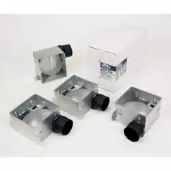
MODELS 670, 671, 671MX, 688 & 689
CEILING/WALL FANS
READ AND SAVE
THESE INSTRUCTIONS
To register this product visit
In USA: www.broan-nutone.com
In Canada: www.broan-nutone.ca
WARNING
TO REDUCE THE RISK OF FIRE, ELECTRIC SHOCK, OR INJURY TO PERSONS, OBSERVE
THE FOLLOWING:
1. Use this unit only in the manner intended by the manufacturer. If you have questions, contact
the manufacturer at the address or telephone number listed in the warranty.
2. Before servicing or cleaning unit, switch power off at service panel and lock the service
disconnecting means to prevent power from being switched on accidentally. When the service
disconnecting means cannot be locked, securely fasten a prominent warning device, such as a
tag, to the service panel.
3. Installation work and electrical wiring must be done by a qualifi ed person(s) in accordance with
all applicable codes and standards, including fi re-rated construction codes and standards.
4. Suffi cient air is needed for proper combustion and exhausting of gases through the fl ue
(chimney) of fuel burning equipment to prevent backdrafting. Follow the heating equipment
manufacturer's guideline and safety standards such as those published by the National Fire
Protection Association (NFPA), and the American Society for Heating, Refrigeration and Air
Conditioning Engineers (ASHRAE), and the local code authorities.
5. When cutting or drilling into wall or ceiling, do not damage electrical wiring and other hidden
utilities.
6. Ducted fans must always be vented to the outdoors.
7. Acceptable for use over a bathtub or shower when installed in a GFCI protected branch circuit.
8. Install fan at least fi ve feet (1.52 m) above the fl oor.
9. Never place a switch where it can be reached from a tub or shower.
10. This unit must be grounded.
CAUTION
1. For general ventilating use only. Do not use to exhaust hazardous or explosive materials
and vapors.
2. To avoid motor bearing damage and noisy and/or unbalanced impellers, keep drywall
spray, construction dust, etc. off power unit.
3. Please read specifi cation label on product for further information and requirements.
USE AND CARE
DISCONNECT ELECTRIC POWER SUPPLY AND LOCK OUT SERVICE PANEL BEFORE
SERVICING THE UNIT.
PREVENTATIVE MAINTENANCE
A clean fan provides better service. Disconnect the power supply and clean the fan as
described below:
TO CLEAN GRILLE - Use a mild detergent, such as dishwashing liquid, and dry with a soft
cloth. DO NOT USE ABRASIVE CLOTHS, STEEL WOOL PADS, OR SCOURING POWDERS.
TO CLEAN FAN ASSEMBLY - Unplug motor cord from receptacle. To remove motor plate:
Find the single tab on the motor plate (located next to the receptacle). Push up near motor
plate tab while pushing out on side of housing. Or insert a straight-blade screwdriver into
slot in housing (next to tab) and twist screwdriver. Gently vacuum fan, motor and interior
of housing. METAL AND ELECTRICAL PARTS SHOULD NEVER BE IMMERSED IN WATER.
TO REASSEMBLE ALL ABOVE PARTS - Reverse all procedures explained above.
MAINTENANCE
The motor is permanently lubricated and never needs oiling. If the motor bearings are
making excessive or unusual noises, replace the motor with the exact service motor. You
should replace the impeller at the same time.
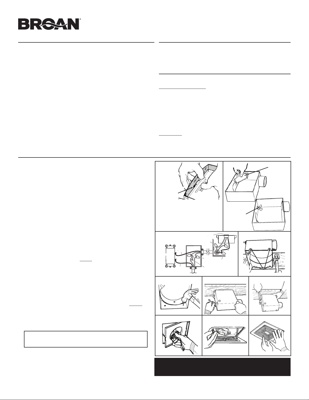
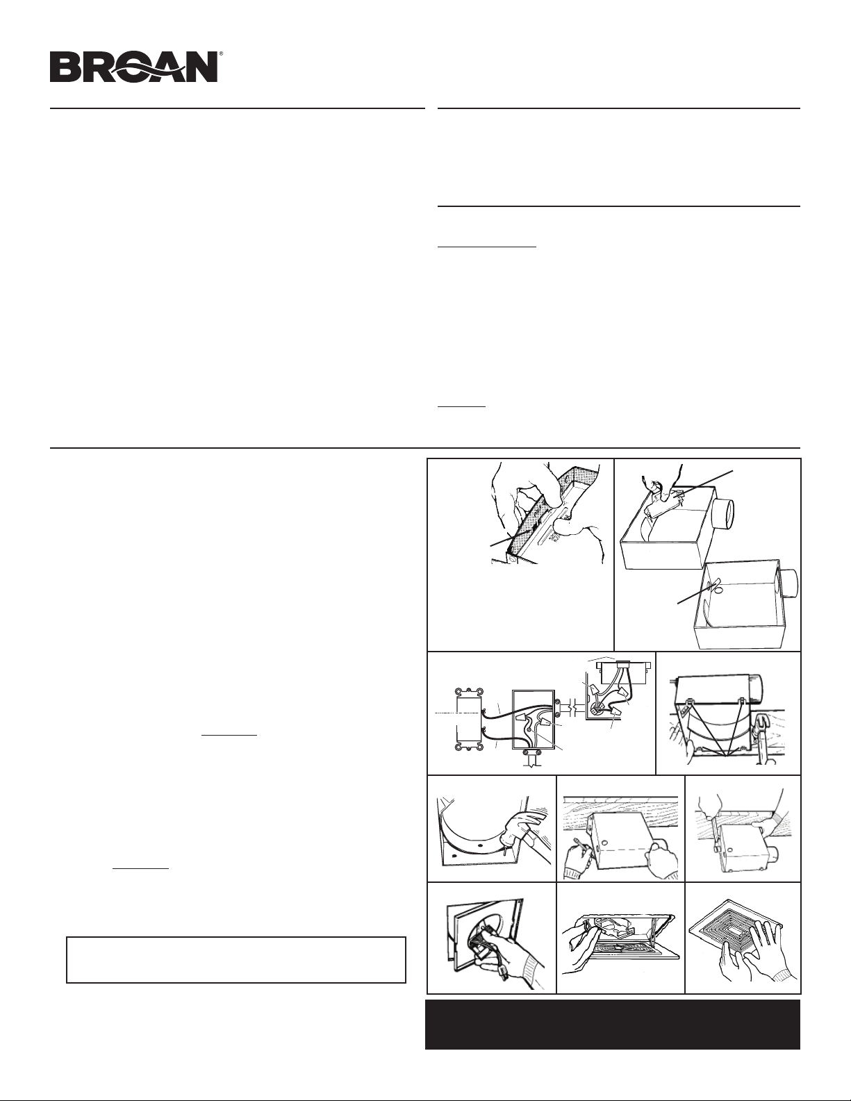
INSTALLATION
1. Remove motor plate from housing by pushing down on rib in plate while pulling out
on side of housing. Motor plate may also be removed by inserting a straight-blade
screwdriver into slot in housing and twisting screwdriver (FIG. 1).
2. Remove wiring cover from housing by pulling straight out. Unit is shipped ready
to wire through the top of housing. To wire through the side, bend housing flap to
cover top hole and expose side hole. DO NOT BREAK OFF FLAP. If flap breaks,
Plug unused hole using standard electrical hole plug (FIG. 2).
3. Turn off electrical power at service entrance and connect power cable to housing
using appropriate connector. Wire black to black, white to white, and green to green
or bare wire.
Push all wiring up into corner of unit and replace wiring cover. Make sure cover
holds housing flap in place against side or top of housing.
CAUTION: DO NOT ALLOW WIRES TO EXTEND OUTSIDE OF WIRING BOX.
Wire left exposed will become pinched or cut when motor plate is installed.
Electrical shock may result (FIG. 3).
4. Choose the location for your fan. For best performance, use the shortest possible
duct run and a minimum number of elbows. For wall installations: Position unit so
damper flap closes when unit is off.
WIRING
COVER
HOUSING
FLAP
SCREWDRIVER
SLOT
FIG. 3
FIG. 1
120 VAC LINE IN
LINEA DE ENTRADA
BLACK
NEGRO
BLACK
NEGRO
GROUND
TIERRA
WHITE TO
WHITE
BLANCO A
BLANCO
SWITCH OR TIMER
INTERRUPTOR O
REGULADOR
GREEN TO
GREEN OR
BARE WIRE
VERDE A
VERDE 0
ALAMBRE
DESNUDO
SWITCH BOX
CAJA DE
INTERRUPTORES
RECEPTACLE
RECEPTÁCULO
WHITE TO
WHITE
BLANCO A
BLANCO
BLACK TO
BLACK
NEGRO A
NEGRO
FIG. 2
FIG. 4
FIG. 5
FIG. 6 FIG. 7
FIG. 8 FIG. 9 FIG. 10
TABS
5. New installation prior to finishing the ceiling or wall:
MAKE SURE HOUSING WILL BE FLUSH WITH FINISHED CEILING OR WALL.
Slotted tabs are provided to locate housing flush with 1/2" ceiling or wall material.
Bend tabs outward 90°
(use a screwdriver if desired) and position housing so that
tabs rest against bottom edge of joists (or front of stud). Nail housing to joist or stud
using four nails to ensure a solid, quiet installation. Ceiling installations: Tabs on
opposite side of housing can be bent outward to rest on top of 1/2" ceiling material
and provide extra stability (FIG. 4).
5. Replacement installation:
Position housing so that it is centered in existing opening. MAKE SURE HOUSING
IS FLUSH WITH FINISHED CEILING OR WALL. After making electrical and
ductwork connections (see steps 4, 5 and 6), nail housing in place. Drive nails
through the housing where indicated by arrows (FIG. 5).
5. New installation in an existing ceiling or wall:
From above ceiling or behind wall, position housing against stud or joist. Trace
outline of housing on ceiling or wall material (FIG. 6). Set housing aside and cut
opening. Place housing in opening such that its BOTTOM EDGE IS FLUSH WITH
FINISHED CEILING OR WALL. 1/2" ceiling or wall material: Bend tabs outward 90°
(use a screwdriver if desired) to rest on top of ceiling or wall material and provide
extra stability. Nail in place using four nails to ensure a solid, quiet installation (FIG. 7).
6. Install 3" round duct onto damper/duct connector. If rigid ductwork is used, its seam
should be positioned at top of damper/duct connector. Tape the joint and extend
ducting to a wall cap or roof cap. Make sure the damper operates freely. Ceiling or
wall can now be finished.
NOTE: If damper detaches from duct connector, re-insert it by squeezing duct
connector top-to-bottom while guiding posts on damper flap into holders in duct
connector. The horizontal rib should be on the outside surface of damper flap
and damper flap should move freely inside of duct connector.
7. Replace the motor plate removed in Step 1. Insert two motor plate tabs into slots
in housing and then pivot motor plate up until the third tab on plate snaps into
matching slot in housing. Make sure tabs hold motor plate securely in place. Plug
in motor (FIG. 8).
8. Squeeze grille springs together and insert springs into slots in motor plate (FIG. 9).
Push grille up against ceiling or wall (FIG. 10).
1111063A
VENTILATEURS À INSTALLATION MURALE OU AU
PLAFOND, MODÈLES 670, 671, 671MX, 688 ET 689
LIRE ET CONSERVER
CES INSTRUCTIONS
Pour enregistrer ce produit, visitez
aux É.-U. : www.broan-nutone.com
au Canada : www.broan-nutone.ca
AVERTISSEMENT
OBSERVEZ LES DIRECTIVES CI-DESSOUS AFIN DE RÉDUIRE LES RISQUES D’INCENDIE,
DE CHOC ÉLECTRIQUE OU DE BLESSURES CORPORELLES:
1. N’utilisez cet appareil que de la manière prévue par le fabricant. Si vous avez des
questions, communiquez avec le fabricant à l’adresse ou au numéro de téléphone
indiqués dans la garantie.
2. Avant de procéder à l’entretien ou au nettoyage de l’appareil, coupez l’alimentation du panneau
électrique et verrouillez l’interrupteur principal afi n d’empêcher que le courant ne soit rétabli
accidentellement. S’il est impossible de verrouiller l’interrupteur principal, fi xez solidement un
message d’avertissement bien visible, par exemple une étiquette, sur le panneau électrique.
3. La pose de l’appareil et les travaux d’électricité doivent être effectués par des personnes
qualifi ées conformément à la réglementation en vigueur, notamment les normes de la
construction ayant trait à la protection contre les incendies.
4. Pour éviter les refoulements, l’apport d’air doit être suffi sant pour brûler les gaz produits par
les appareils à combustion et les évacuer dans le conduit de fumée (cheminée). Respectez
les directives du fabricant de l’appareil de chauffage et les normes de sécurité, notamment celles
publiées par la National Fire Protection Association (NFPA), l’American Society for Heating,
Refrigeration and Air Conditioning Engineers (ASHRAE) et les codes des autorités locales.
5. Veillez à ne pas endommager le câblage électrique ou d’autres équipements non
apparents lors de la découpe ou du perçage du mur ou du plafond.
6. Les ventilateurs canalisés doivent toujours rejeter l’air à l’extérieur.
7. Cet appareil peut être installé au-dessus d’une enceinte de baignoire ou de douche s’il est
branché sur un circuit de dérivation protégé par un disjoncteur de fuite à la terre.
8 Installer le ventilateur à au moins 5 pi (1,52 m) au-dessus du plancher.
9 Ne jamais installer un interrupteur à portée d'une baignoire ou d'une douche.
10. Cet appareil doit être relié à une mise à la terre.
ATTENTION
1. Pour ventilation générale uniquement. N’utilisez pas cet appareil pour évacuer des
matières ou des vapeurs dangereuses ou explosives.
2. Pour éviter d’endommager les roulements du moteur, de déséquilibrer les pales ou de les
rendre bruyantes, débarrassez l’appareil de la poussière de plâtre, de construction, etc.
3. Veuillez lire l’étiquette de spécifi cations du produit pour obtenir plus de
renseignements, notamment sur les exigences.
UTILISATION ET ENTRETIEN
AVANT D'EFFECTUER L'ENTRETIEN DE L'APPAREIL, COUPER LE COURANT ET
VERROUILLER LE PANNEAU DE DISTRIBUTION ÉLECTRIQUE.
ENTRETIEN PRÉVENTIF
Un ventilateur propre fournit le meilleur rendement. Coupez le courant et nettoyez le
ventilateur comme suit :
POUR NETTOYER LA GRILLE : Utilisez un détergent doux, tel qu'un détergent liquide à
vaisselle et essuyer avec un linge doux. NE PAS UTILISER DE TAMPONS ABRASIFS, DE
LAINES D'ACIER OU DE POUDRES À RÉCURER.
POUR NETTOYER LE BLOC VENTILATEUR : Débrancher le cordon d'alimentation du moteur.
Pour retirer la plaque moteur : Repérer l’unique PATTE sur la plaque moteur (située près
de la prise). Pousser vers le haut près de la patte de la plaque moteur, tout en poussant
vers l’extérieur sur le côté du boîtier, ou insérer un tournevis à lame plate dans la fente
du boîtier (à côté de la patte) et faire tourner le tournevis. Passer doucement l'aspirateur
sur le moteur et l'intérieur du boîtier. LES PIÈCES MÉTALLIQUES ET ÉLECTRIQUES NE
DOIVENT JAMAIS ÊTRE IMMERGÉES DANS L'EAU.
POUR REMETTRE EN PLACE LES PIÈCES CI-DESSUS : Inverser les procédures ci-dessus..
ENTRETIEN
Le moteur est lubrifi é à vie. Ne pas huiler. Si les roulements du moteur sont plus bruyants
qu’à l’habitude, remplacer le moteur par le même moteur de rechange. La roue du ventilateur
doit également être remplacée.
INSTALLATION
1. Retirer la plaque moteur du boîtier sur le pli de la plaque tout en tirant vers l'extérieur le côté
du boîtier. La plaque moteur peut aussi être retirée en insérant la lame plate d'un tournevis
dans la fente du boîtier et faisant tourner la lame (FIG. 1).
2. Retirer le couvercle de câblâge en le tirant hors du boîtier. L'appareil est confi guré à l'usine
pour être câblé par le dessus du boîtier. Pour le câbler par le côté, plier le rabat du boîtier pour
couvrir le trou du dessus et découvrir le trou latéral. NE PAS BRISER LE RABAT. Si le rabat est
brisé, boucher le trou non utilisé à l'aide d'un bouchon d'orifi ce électrique standard (FIG. 2).
3. Couper le courant au panneau de distribution électrique et connecter les fils
d'alimentation électrique à l'aide de capuchons de connexion appropriés. Connecter le
fi l noir au noir, le blanc au blanc et le fi l vert au fi l vert ou au fi l dénudé.
Pousser tout le
câblage dans le coin de l'appareil et remettre en place le couvercle du câblage. S'assurer
que le couvercle retient le rabat contre le côté ou le dessus du boîtier.
ATTENTION : NE PAS PERMETTRE AUX FILS DE SORTIR DU BOÎTIER DE CÂBLAGE. Les ls
hors du boîtier seront pincés ou coupés lors de la remise en place de la plaque moteur.
Un choc électrique pourrait survenir (FIG. 3).
4. Choisir l'emplacement du ventilateur. Pour le meilleur rendement, utiliser lesconduits les
plus courts et un minimum de coudes. Pour les installations murales : placer l'appareil pour
que son clapet ferme lorsqu'il n'est pas en marche.
COUVERCLE
DE CÂBLAGE
RABAT DU
BOÎTIER
FENTE POUR
TOURNEVIS
FIG. 3
FIG. 1
BLACK
NEGRO
BLACK
NEGRO
GROUND
TIERRA
WHITE TO
WHITE
BLANCO A
BLANCO
SWITCH OR TIMER
INTERRUPTOR O
REGULADOR
GREEN TO
GREEN OR
BARE WIRE
VERDE A
VERDE 0
ALAMBRE
DESNUDO
SWITCH BOX
CAJA DE
INTERRUPTORES
RECEPTACLE
RECEPTÁCULO
WHITE TO
WHITE
BLANCO A
BLANCO
BLACK TO
BLACK
NEGRO A
NEGRO
FIG. 2
PRISE
FIG. 4
FIG. 5
FIG. 6 FIG. 7
FIG. 8 FIG. 9 FIG. 10
PATTES
5. Nouvelle installation avant la nition du plafond ou du mur :
S'ASSURER QUE LE BOÎTIER SERA À RAS AVEC LE MUR OU LE PLAFOND FINI. Des pattes
munies de fentes sont présentes pour placer le boîtier à ras avec le matériau de fi nition de
1/2 po, pour plafond ou mur. Plier les pattes à 90° vers l'extérieur
(utiliser un tournevis si
désiré) et placer le boîtier de façon à ce que ses pattes s'appuient à la base des solives (ou à
l'avant d'un montant). Utiliser 4 clous pour clouer le boîtier aux solives ou au montant pour
assurer une installation solide et silencieuse. Installations au plafond : Des pattes du côté
opposé au boîtier peuvent être pliées vers l'extérieur pour le poser sur le dessus du matériau
de plafond de 1/2 po et fournir une stabilité supplémentaire (FIG. 4).
5. Installation pour remplacer un ancien appareil :
Placer le boîtier au centre de l'ouverture existante.
S'ASSURER QUE LE BOÎTIER EST
À RAS AVEC LE MUR OU LE PLAFOND FINI.
Une fois les connexions électriques et le
raccordement au conduit terminés (voir les étapes 4, 5 et 6), clouer le boîtier en place.
Enfoncer les clous dans le boîtier où il est indiqué par les fl èches (FIG. 5).
5. Nouvelle installation dans un mur ou un plafond déjà ni :
Par le dessus du plafond ou derrière le mur, appuyer le boîtier contre un montant ou une
solive. Tracer le contour du boîtier sur le matériau du plafond ou du mur (FIG. 6). Mettre de
côté le boîtier et découper l'ouverture. Placer le boîtier pour que SA BASE SOIT
À RAS AVEC
LE MUR OU LE PLAFOND FINI.
Pour un matériau de plafond ou de mur de 1/2 po : plier les
pattes
à 90° vers l'extérieur
(utiliser un tournevis si désiré)
pour le poser sur le matériau
de mur ou de plafond et fournir une stabilité supplémentaire.
Utiliser 4 clous pour clouer le
boîtier pour assurer une installation solide et silencieuse
(FIG. 7).
6. Raccorder un conduit rond de 3 po au clapet/raccord de conduit. Si un conduit rigide
est utilisé, son joint de soudure doit être placé vers le haut du clapet/raccord de
conduit. Scotcher le joint. Déployer le conduit jusqu'au capuchon de mur ou de toit. S'assurer
que le clapet ouvre librement. Efffectuer la fi nition du plafond ou du mur.
NOTE : Si le clapet se détache du raccord de conduit, le remettre en place en pinçant
le haut du raccord de conduit vers le bas tout en insérant les tiges du clapet dans ses
supports dans le raccord de conduit. Le pli horizontal doit être sur la surface extérieure
du clapet et celui-ci doit pouvoir bouger librement.
7. Remettre en place la plaque moteur retirée à l'étape 1. Insérer 2 pattes de la plaque moteur
dans les fentes du boîtier et incliner la plaque moteur jusqu'à ce que sa troisième patte
s'enclenche dans sa fente dans le boîtier. S'assurer que les pattes retiennent bien la plaque
moteur. Brancher le moteur (FIG. 8).
8. Pincer les ressorts de grille ensemble et les insérer dans les fentes de la plaque moteur (FIG. 9).
Pousser la grille contre le plafond ou le mur (FIG. 10).
1111063A
VERT À
VERT OU
FIL NU
NOIR À
NOIR
BLANC À
BLANC
MISE
À LA
TERRE
ENTRÉE 120 VCA
NOIR
NOIR
BLANC À
BLANC
INTERRUPTEUR
OU MINUTERIE
BOÎTIER
D'INTERRUPTEUR