
Owner's Manual
16.5 HP
ELECTRIC START
42" MOWER
AUTOMATIC
LAWN TRACTOR
Model No.
917.271642
£Z 3
• Safety
• Assembly
• Operation
• Maintenance
• Repair Parts
CAUTION:
Read and follow all Safety
Rules and Instructions before
operating this equipment.
Foranswersto yourquestions
aboutthis product,Call:
1-800-659-5917
Sears Craftsman Help Line
5 am - 5 pm, Mon- Sat
Sears, Roebuck and Co., Hoffman Estates, II 60179
Visit our Craftsman website:www.sears.comJcraffsman
Warranty ............................................... 2
Safety Rules ......................................... 3
Product Specifications .......................... 6
Assembly .............................................. 8
Operation ............................................ 11
Maintenance ....................................... 18
Maintenance Schedule ...................... 18
Service and Adjustments.................... 22
Storage ............................................... 29
Troubleshooting ................................. 30
Repair Parts........................................ 34
Parts Ordering ..................... Back Cover
LIMITED TWOYEAR WARRANTY ON CRAFTSMAN RIDING EQUIPMENT PARTS
For two (2) years from the date of purchase, if thisCraftsman Riding Equipmentis
maintained, lubricated and tuned up according to the instructionsin the owner's
manual, Sears will repair or replace, free of charge, any partsfound to be defective in
material or workmanship. Warranty service is available free of charge by taking your
Craftsman riding equipment to your nearest Sears Service Center. In-home warranty
service is available but a trip charge will apply. This warranty applies only while this
productis in the United States.
ThisWarranty does not cover:
• Expendable items which become worn during normal use, such as blades, spark
plugs,air cleaners, belts and oil filters.
• Tire replacement or repair caused by punctures from outside objects, suchas nails,
thorns, stumps, or glass.
• Repairs necessary because of operator abuse, includingbut not limitedto, damage
caused by towing objects beyond the capability of the riding equipment, impacting
objectsthat bend the frame or crankshaft, or over speeding the engine.
• Repairs necessary because of operator negligence, includingbut not limited to,
electrical and mechanical damage caused by improper storage, failure to use the
proper grade and amount of engine oil, failure to keep the deck clear offlammable
debris, or the failure to maintain the equipment according to the instructions
contained in the owner's manual.
• Engine (fuel system) cleaning or repairs caused by fuel determined to be contami-
nated or oxidized (stale). In general, fuel should be used withinthirty (30) days of its
purchase date.
• Riding equipment used for commercial or rental purposes.
LIMITED 90 DAYWARRANTY ON BATTERY
For ninety (90) days from date of purchase, if any battery includedwith this riding
equipment proves defective in material or workmanship and our testing determines
the battery will not hold a charge, Sears will replace the battery at no charge. War-
ranty service is available free of charge by taking your Craftsman riding equipment to
your nearest Sears Service Center. In-home warranty service isavailable buta trip
charge will apply.This warranty applies onlywhile this productis in the United States.
TO LOCATE THE NEAREST SEARS SERVICE CENTER OR TO SCHEDULE IN-
HOME WARRANTY SERVICE, SIMPLY CONTACT SEARS AT 1-800-4-MY-HOME
ThisWarranty gives you specific legal rights, and you may also have other rights
whichmay vary from state tostate.
Sears, Roebuck and Co., D/817 WA, Hoffman Estates, IL 60179
2

IMPORTANT: This cutting machine is capable of amputating hands and feet and
throwing objects. Failure to observe the followingsafety instructions couldresult in
seriousinjury or death.
I. GENERAL OPERATION
• Read, understand, and follow all
instructionsin the manual and on the
machine before starting.
• Only allow responsible adults, who are
familiar with the instructions,to operate
the machine.
• Clear the area of objects such as
rocks, toys,wire, etc., which could be
picked up and thrown by the blade.
• Be sure the area is clear ofother
people before mowing. Stop machine
if anyone enters the area.
• Never carry passengers.
• Do not mow in reverse unless abso-
lutely necessary. Always lookdown
and behind before and while backing.
• Be aware of the mower discharge
direction and do notpoint it at anyone.
Do not operate the mower without
either the entire grass catcher or the
guard in place.
• Slow down before turning.
• Never leave a running machine
unattended. Always turn off blades, set
parking brake, stop engine, and
remove keys before dismounting.
• Turn off blades when not mowing.
• Stop engine before removing grass
catcher or unclogging chute.
• Mow only in daylight or good artificial
light.
• Do not operate the machine while
under the influence of alcohol or drugs.
• Watch for traffic when operating near or
crossing roadways.
• Use extra care when loading or
unloading the machine into a trailer or
truck.
• Data indicatesthat operators, age 60
years and above, are involved in a
large percentage of riding mower-
related injuries. These operators
should evaluate their ability to operate
the riding mower safely enough to
protect themselves and others from
serious injury.
II. SLOPE OPERATION
Slopes are a majorfactor related toloss-of-
control and tipover accidents, which can
resultin severe injuryor death. All slopes
requireextra caution. Ifyou cannot back up
the slope or ifyou feel uneasy on it, do not
mow it.
DO:
• Mow up and down slopes, notacross.
• Remove obstacles such as rocks, tree
limbs, etc.
• Watch for holes, ruts,or bumps,
Uneven terrain could overtum the
machine. Tall grass can hide ob-
stacles.
• Use slow speed. Choose a low gear
so that you will nothave to stop or shift
while on the slope.
• Followthe manufacturer's recommen-
dations for wheel weights or counter-
weights to improve stability.
• Use extra care with grass catchers or
other attachments. These can change
the stability ofthe machine.
• Keep all movement on the slopes slow
and gradual. Do not make sudden
changes in speed or direction.
• Avoid starting or stoppingon a slope. If
tires lose traction, disengage the
blades and proceed slowly straight
down the slope.
DO NOT:
• Do not turn on slopes unless neces-
sary, and then, turn slowly and gradu-
ally downhill, if possible.
• Do notmow near dropoffs, ditches, or
embankments. The mower could
suddenly turn over if a wheel isover
the edge of a cliffor ditch, or if an edge
caves in.
• Do not mow on wet grass. Reduced
traction could cause sliding.
• Do not try to stabilize the machine by
puttingyour foot on the ground.
• Donotusegrasscatcheronsteep
slopes.
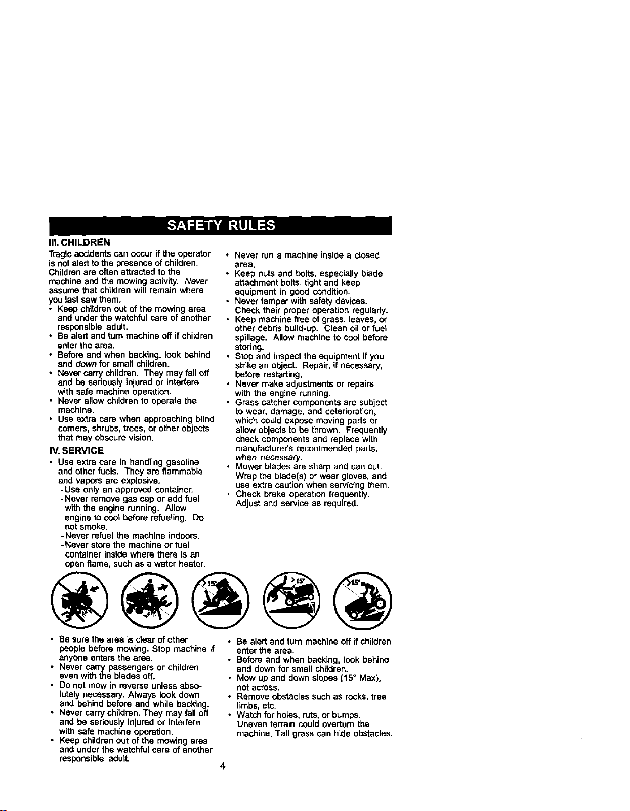
IlLCHILDREN
Tragic accidents can occur if the operator
isnot alert to the presence of children.
Children are often attracted to the
machine and the mowing activity. Never
assume that children will remain where
you last sew them.
• Keep children out of the mowing area
and under the watchful care of another
responsible adult.
• Be alert and turn machine off if children
enter the area.
• Before and when backing, look behind
and down for small children.
• Never carry children. They may fall off
and be seriously injured or interfere
with safe machine operation.
• Never allow children to operate the
machine.
• Use extra care when approaching blind
comers, shrubs,trees, or other objects
that may obscure vision,
IV. SERVICE
• Use extra care in handling gasoline
and other fuels. They ere flammable
end vapors ere explosive.
-Use only an approved container.
- Never remove gas cap or add fuel
with the engine running. Allow
engine to cool before refueling. Do
not smoke.
-Never refuel the machine indoors.
-Never storethe machine or fuel
container inside where there is an
open flame, such as a water heater.
• Never run a machine inside a closed
area.
• Keep nuts and bolts, especially blade
attachment bolts, tight and keep
equipment in good condition.
• Never tamper with safety devices.
Check their proper operation regularly.
• Keep machine free of grass, leaves, or
other debris build-up. Clean oil or fuel
spillage. Allow machine to cool before
storing.
• Stop and inspect the equipment if you
strike an object. Repair, if necessary,
before restarting,
• Never make adjustments or repairs
with the engine running.
• Grass catcher components are subject
to wear, damage, and deterioration,
which could expose moving parts or
allow objects to be thrown. Frequently
check components and replace with
manufacturer's recommended parts,
when necessary.
• Mower blades are sharp and can cut.
Wrap the blade(s) or wear gloves, and
use extra caution when servicing them.
• Check brake operation frequently.
Adjust and service as required.
• Be sure the area is clear of other
people before mowing. Stop machine if
anyone enters the area.
• Never carry passengers or children
even with the blades off.
• Do not mow in reverse unless abso-
lutely necessary, Always look down
and behind before and while backing.
• Never carry children. They may fall off
and be seriously injured or interfere
with safe machine operation,
• Keep children out of the mowing area
and under the watchful care of another
responsible adult.
• Be alert and turn machine off if children
enterthe area,
• Before and when backing, look behind
end down for small children.
• Mow up and down slopes (15° Max),
notacross.
• Remove obstacles such as rocks,tree
limbs, etc.
• Watch for holes, ruts,or bumps.
Uneven terrain could overturn the
machine. Tall grass can hide obstacles.
4

• Use slow speed. Choose a low gear so
thatyou will not have to stop or shift
while on the slope.
• Avoid starting or stopping on a slope. If
tires lose traction, disengage the
blades and proceed slowly straight
down the slope.
• If machine stops while going uphill,
disengage blades, shift into reverse
and back down slowly.
• Do notturn on slopes unless neces-
san/, and then, turn slowly and gradu-
ally downhill, if possible.
_,Look for this symbol to pointout
importantsafety precautions. It means
CAUTION!!! BECOME ALERT!!! YOUR
SAFETY IS INVOLVED.
CAUTION: In orderto prevent
accidental starting when setting up,
transporting, adjusting or making repairs,
always disconnect spark plug wire and
place wire where it cannot contact spark
CAUTION: Do not coast down a hill
in neutral, you may lose control of the
tractor.
_i, CAUTION: Tow onlythe attachments
that are recommended by and comply
with specificationsof the manufacturer of
your tractor. Use common sense when
towing. Operate only at the lowest
possiblespeed when on a slope. Too
heavy of a load, while on a slope, is
dangerous. Tires can lose traction with
the ground and cause you to lose Control
ofyour tractor.
_WARNING: Engine exhaust, some of
its constituents, and certain vehicle
components contain or emit chemicals
known to the State of Californiato cause
cancer and birthdefects or other repro-
ductive harm.
_I_WARNING: Battery posts,terminals
and related accessories contain lead and
lead compounds, chemicals known to the
State of California to cause cancer and
birthdefects or other reproductive harm.
Wash hands after handling.
5
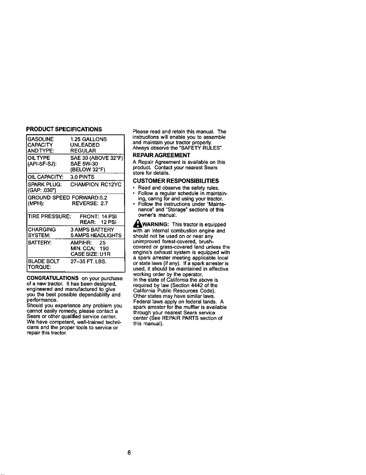
PRODUCT SPECIFICATIONS
GASOLINE 1.25 GALLONS
CAPACITY UNLEADED
ANDTYPE: REGULAR
OILTYPE SAE 30 (ABOVE 32"F
API-SF-SJ): SAE 5W-30
(BELOW 32"F)
OIL CAPACITY: 3.0 PINTS
SPARK PLUG: CHAMPION RC12YC
GAP: .030")
GROUND SPEED FORWARD:5.2
MPH): REVERSE: 2.7
TIRE PRESSURE: FRONT: 14 PSi
REAR: 12PSI
CHARGING 3 AMPS BATTERY
SYSTEM: 5AMPS HEADLIGHTS
BATTERY: AMP/HR: 25
MIN. CCA: 190
CASE SIZE: U1R
BLADE BOLT 27-35 FT. LBS.
TORQUE:
CONGRATULATIONS on your purchase
of a new tractor. It has been designed,
engineered and manufactured to give
you the best possible dependability and
performance.
Should you experience any problem you
cannot easily remedy, please contact a
Sears or other qualified service center.
We have competent, well-trained techni-
ciansand the proper tools to service or
repair thistractor.
Please read and retain this manual. The
instructions will enable you to assemble
and maintainyour tractor properly.
Always observe the "SAFETY RULES".
REPAIR AGREEMENT
A Repair Agreement is available on this
product. Contact your nearest Sears
store for details.
CUSTOMER RESPONSIBILITIES
• Read and observe the safety rules.
• Follow a regular schedule in maintain-
ing, cadng for and using your tractor.
• Follow the instructionsunder "Mainte-
nance" and "Storage" sections of this
owner's manual.
_kWARNING: This tractor isequipped
with an internal combustion engine and
should not be used on or near any
unimproved forest-covered, brush-
covered or grass-coverad land unless the
engine's exhaust system is equipped with
a spark arrester meeting applicable local
or state laws (if any). Ifa spark arrester is
used, it should be maintained in effective
workingorder by the operator.
In the state ofCalifornia the above is
required by law (Section 4442 of the
California Public Resources Code).
Other states may have similar laws.
Federal laws apply on federal lands. A
spark arraster for the muffler is available
through your nearest Sears service
center (See REPAIR PARTS sectionof
this manual).
6
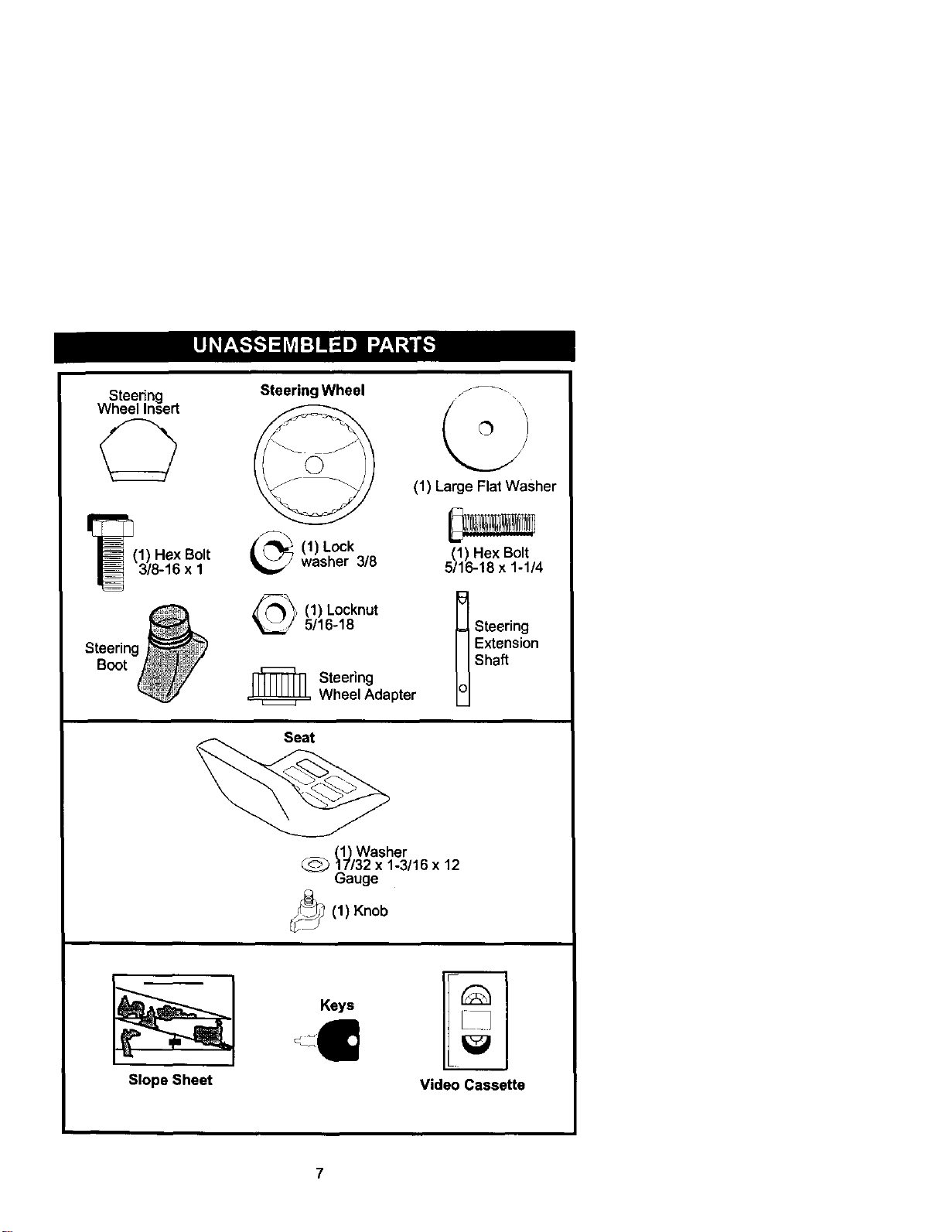
Steedng
Wheel Insert
I_(1) Hex Bolt
3/8-16 x 1
Steering Wheel
1) Lockwasher 3/8
(1) Locknut
5/16-18
_ Steering
Wheel Adapter
(1) Large Flat Washer
(1) Hex Bolt
5/16-18 x 1-1/4
t Steering
EhXtaeftns1°n
Seat
(_Washer
C_17/32 x 1-3/16 x 12
Gauge
1) Knob
Slope Sheet
Keys
Video Cassette
Your newtractor has been assembled at the factory with exceptionof those parts left
unassembled for shipping purposes. To ensure safe and proper operation of your
tractor all parts and hardware you assemble must be tightened securely. Use the
correcttools as necessary to insure proper tightness. Review the video cassette before
you begin.
TOOLS REQUIRED FOR
ASSEMBLY
A socket wrench set will make assembly
easier. Standard wrench sizes you need
are listed betow.
(1) 9/16"wrench (1) Pliers
(2) 1/2"wrench (1) Utility knife
(1) Tire pressure gauge
When right or left hand is mentioned in
this manual, it means, from your pointof
view, when you are in the operating
position(seated behind the steering
wheel).
TO REMOVETRACTOR FROM
CARTON
UNPACK CARTON
1. Remove all accessible loose parts
and parts cartons from carton.
2. Cut, from top to bottom, along lines
on all fourcomers of carton, and lay
panels fiat.
3. Check for any additional loose parts
or cartons and remove•
BEFORE REMOVINGTRACTOR
FROM SKID
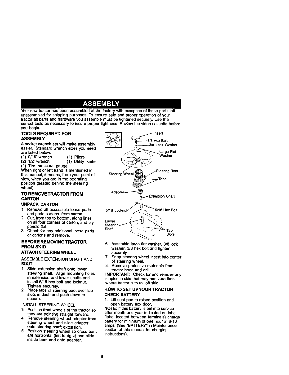
ATTACHSTEERINGWHEEL
ASSEMBLE EXTENSION SHAFT AND
BOOT
1. Slide extension shaft onto lower
steering shaft. Align mounting holes
in extension and lower shafts and
install 5/16 hex bolt and Iocknut.
Tighten securely.
2. Place tabs of steering boot over tab
slots in dash and push down to
secure.
INSTALL STEERING WHEEL
3. Positionfrontwheels ofthe tractor so
they are pointing straight forward.
4. Remove steering wheel adapter from
steering wheel and slide adapter
onto steering shaft extension.
5. Positionsteering wheel so cross bars
are horizontal (left to right) and slide
inside boot and onto adapter.
_--_3/8 HexBolt
_3/8 LockWasher
ff _ LargeFiat
• _'_ . , Washer
St
SteeringWheelS
eedng
Boot
Tabs
Adapter-----"--'_
,/,_ ExtensionShaft
Lower ",
Steering _. , J
Shaft _,."""- Tab
-,.. ,,;, Slots
6. Assemble large flat washer, 3/8 lock
washer, 3/8 hex boltand tighten
securely•
7. Snap steering wheel insert into center
of steering wheel.
8. Remove protective materials from
tractor hood and grill.
IMPORTANT: Check for and remove any
staples in skid that may puncture tires
where tractor isto roll off skid.
HOWTO SET UPYOURTRACTOR
CHECK BATrERY
1. Liftseat pan to raised positionand
open battery box door.
NOTE: Ifthis battery isput intoservice
after month and year indicated on label
(label located between terminals) charge
battery for minimum of one hour at 6-10
amps. (See "BATTERY" in Maintenance
section of this manual for charging
instructions).
8
Batten/
Door
Terminal
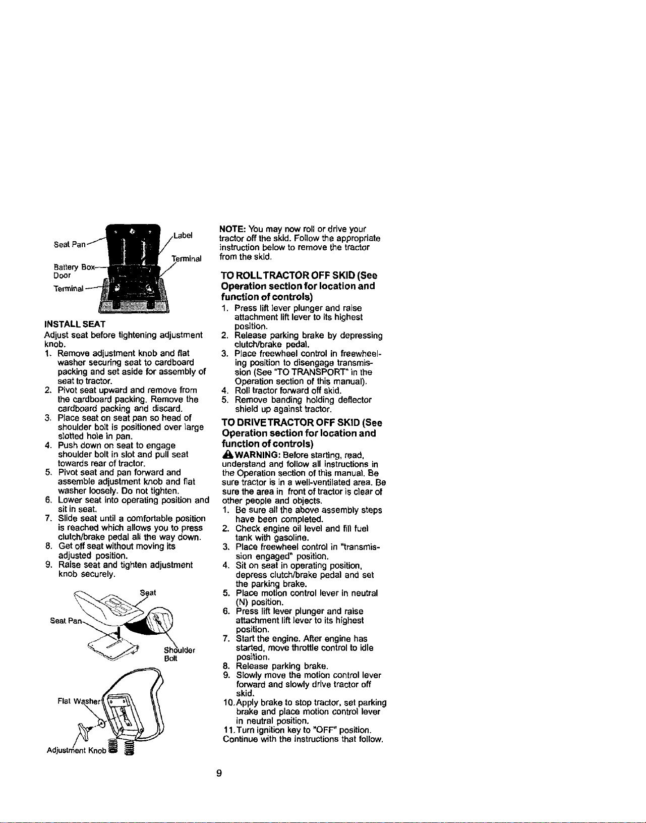
INSTALL SEAT
Adjust seat before tightening adjustment
knob.
1. Remove adjustment knob and fiat
washer secudng seat to cardboard
packing and set aside for assembly of
seat totractor.
2. Pivot seat upward and remove from
the cardboard packing. Remove the
cardboard packing and discard.
3. Place seat on seat pan so head of
shoulder bolt is positioned over large
s}otted hole in pan.
4. Push down on seat to engage
shoulder bolt in slot and pull seat
towards rear of tractor.
5, Pivotseat and pan forward and
assemble adjustment knob and flat
washer loosely. Do not tighten.
6. Lower seat intooperating positionand
sit in seat.
7. Slide seat untila comfortable position
is reached which allows you to press
clutch/brake pedal all the way down.
8. Get off seat without moving its
adjusted position.
9. Raise seat and tighten adjustment
knob securely.
Seat
Shkoulder
Bolt
NOTE: You may now roll or drive your
tractor off the skid. Follow the appropriate
instruction below to remove the tractor
from the skid.
TO ROLLTRACTOR OFF SKID (See
Operation section for location and
function of controls)
1. Press lift lever plunger and raise
attachment liftlever to its highest
position.
2. Release parking brake by depressing
clutch/brake pedal.
3. Place freewheel control in freewheel-
ing positionto disengage transmis-
sion (See "TO TRANSPORT" in the
Operation section of this manual),
4. Roll tractor forward off skid.
5. Remove banding holding deflector
shield up against tractor.
TO DRIVETRACTOR OFF SKID (See
Operation section for location and
function of controls)
_kWARNING: Before starting, read,
understand and follow all instructionsin
the Operation section of this manual. Be
sure tractor isin a welt-ventilated area. Be
sure the area in front of tractor isclear of
other people and objects.
1. Be sure all the above assembly steps
have been completed.
2. Check engine oillevel and fill fuel
tank with gasoline.
3. Place freewheel controlin "transmis-
sion engaged" position.
4. Sit on seat in operating position,
depress clutch/brake pedal and set
the parking brake.
5. Place motioncontrol lever in neutral
(N) position.
6. Press lift lever plunger and raise
attachment liftlever to its highest
position.
7. Start the engine. After engine has
started, move throttle controlto idle
position.
8. Release parking brake.
9. Slowly move the motion control lever
forward and slowly drive tractor off
skid.
10.Apply brake to stop tractor, set parking
brake and place motion control lever
in neutral position.
11.Turn ignition keyto "OFF" position.
Continue with the instructionsthat follow.
9
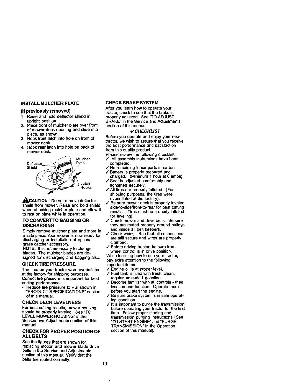
INSTALLMULCHERPLATE
(If previously removed)
1. Raise and hold deflector shield in
upright position.
2. Place front of mulcher plate over front
of mower deck opening and slide into
place, as shown.
3. Hook frontlatch into hole on front of
mower deck.
4. Hook rear latch into hole on back of
mower deck.
Mulcher
Deflector Plate
Shield
Latch
A
_NLCAUTION: Do not remove deflector
shield from mower. Raise and hold shield
when attaching mulcher plate and allow it
to rest on plate while in operation.
TO CONVERTTO BAGGING OR
DISCHARGING
Simply remove mulcher plate and store in
a safe place.Yourmower is now ready for
discharging or installation of optional
grass catcher accessory.
NOTE: It isnot necessary to change
blades. The mulcher blades are de-
signed for discharging and bagging also.
CHECKTIRE PRESSURE
The tires on yourtractor were overinflated
at the factoryfor shipping purposes.
Correct tire pressure is important for best
cutting performance.
• Reduce tire pressure to PSI shown in
"PRODUCT SPECIFICATIONS" section
of this manual,
CHECK DECK LEVELNESS
For best cutting results, mower housing
should be properly leveled. See "TO
LEVEL MOWER HOUSING" inthe
Service and Adjustments section of this
manual.
CHECK FOR PROPER POSITION OF
ALL BELTS
See the figures that are shown for
replacing motion and mower blade drive
belts in the Service and Adjustments
sectionof this manual. Verify that the
belts are routed correctly.
CHECK BRAKE SYSTEM
After you learn how to operate your
tractor,checkto see that the brake is
properly adjusted. See "TO ADJUST
BRAKE" in the Service and Adjustments
sectlon of this manual.
_ CHECKLIST
Before you operate and enjoy your new
tractor,we wish to assure that you receive
the best performanceand satisfaction
from this quality product.
Please review the following checklist:
`/ All assembly instructionshave been
completed.
`/No remaining loose parts in carton.
`/Battery is properly prepared and
charged. (Minimum 1 hour at 6 amps).
`/Seat is adjusted comfortably and
tightened securely.
,/All tires are properly inflated. (For
shipping purposes, the tires were
overinflated at the factory).
4" Be sure mower deck is properly leveled
side-to-side/front-to-rear for best cutting
results. (Tires must be properly inflated
for leveling).
`/Check mower and drive belts. Be sure
they are routed properly around pulleys
and inside all belt keepers.
`/Check wiring. See that all connections
are still secure and wires are properly
clamped.
`/Before driving tractor, be sure free-
wheel control is in drive position.
While learning how to use your tractor,
pay extra attention to the following
important items:
`/Engine oil isat proper level.
,/Fuel tank is filled with fresh, clean,
regular unleaded gasoline.
,/Become familiar with all controls - their
location and function. Operate them
before you start the engine.
,/Be sure brake system is in safe operat-
ing condition.
,/It is important to purge the transmission
before operating your tractor for the first
time. Follow proper starting and
transmission purging instructions (See
"TO START ENGINE" and "PURGE
TRANSMISSION" in the Operation
sectionof this manual).
10
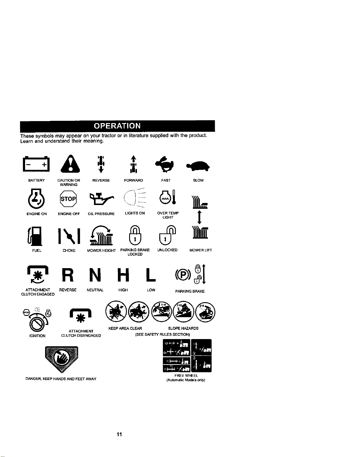
These symbols may appear on your tractor or in literature suppliedwith the product.
Learn and understand their meaning.
BA]_ERY CAUTION OR REVERSE FORWARD FAST
WARNING
ENGINE ON ENGINE OFF OIL PRESSURE LIGHTS ON OVER TEMP
LIGHT
i I'.,I 0 0
FUEL CHOKE MOWER HEIGHT PARKING BRAKE UNLOCKED
LOCKED
SLOW
L
!
MOWERLI_
_r_R N H L
ATTACHMENT REVERSE NEUTRAL HIGH LOW PARKING BRAKE
CLUTCH ENGAGED
KEEP AREA CLEAR SLOPE HAZARDS
ATrACHMENT
IGNITION CLUTCH DISENGAGED
DANGER, KEEP HANDS AND FEET AWAY
(SEE SAFETY RULES SECTION)
FREE WHEEL
(Automatic Models only)
11
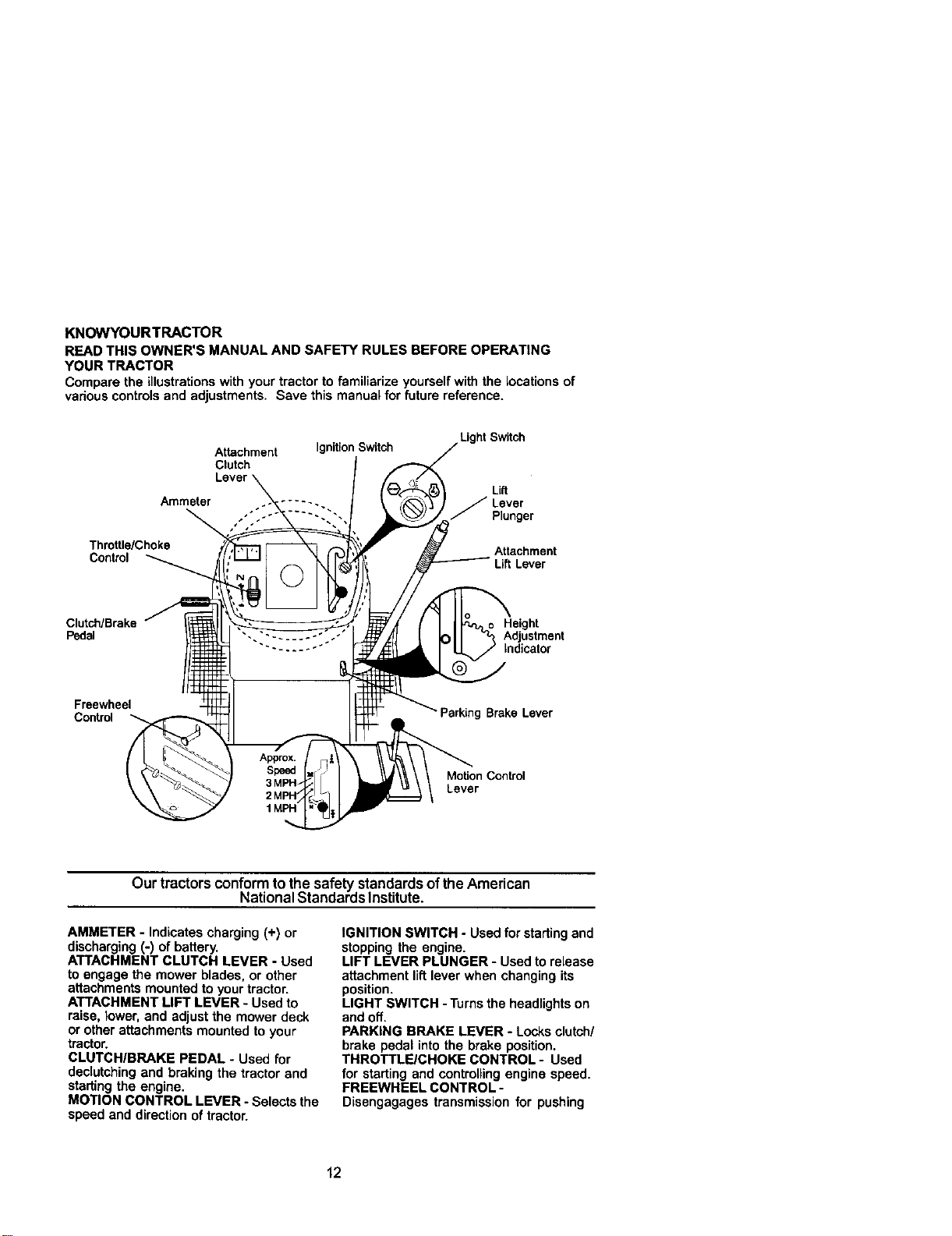
KNOWYOURTRACTOR
READ THIS OWNER'S MANUAL AND SAFETY RULES BEFORE OPERATING
YOUR TRACTOR
Compare the illustrations with your tractor to familiarize yourself with the locations of
various controlsand adjustments. Save this manual for future reference.
Attachment IgnitionSwitch
Clutch
Lever
Ammeter ..... .
Light Switch
L_
J Lever
Plunger
Throttle/Choke Attachment
Control Lift Lever
Clutch/Brake Height
Pedal Adjustment
Indicator
Freewheel
Control Parking Brake Lever
MoUon Control
Lever
Our tractors conformto the safety standardsof the American
National Standards Institute.
AMMETER - Indicates charging (+) or
discharging (-) of battery.
ATTACHMENT CLUTCH LEVER - Used
to engage the mower blades, or other
attachments mounted to your tractor.
ATTACHMENT LIFT LEVER - Used to
raise, tower,and adjust the mower deck
or other attachments mounted to your
tractor.
CLUTCH/BRAKE PEDAL - Used for
declutching and braking the tractor end
starting the engine.
MOTION CONTROL LEVER - Selects the
speed and directionof tractor.
IGNITION SWITCH - Used for starting and
stopping the engine.
LIFT LEVER PLUNGER - Used torelease
attachment lift lever when changing its
position.
LIGHT SWITCH - Turns the headlights on
and off.
PARKING BRAKE LEVER - Locks clutch/
brake pedal intothe brake position.
THROTTLE/CHOKE CONTROL- Used
for starting and controlling engine speed.
FREEWHEEL CONTROL -
Disengagages transmission for pushing
12
The operation of any tractor can resultin foreign objects thrown into
the eyes, which can result in severe eye damage. Always wear safety
glasses or eye shields while operating your tractor or performing any
adjustments or repairs. We recommend a wide vision safety mask
over spectacles or standard safety glasses,
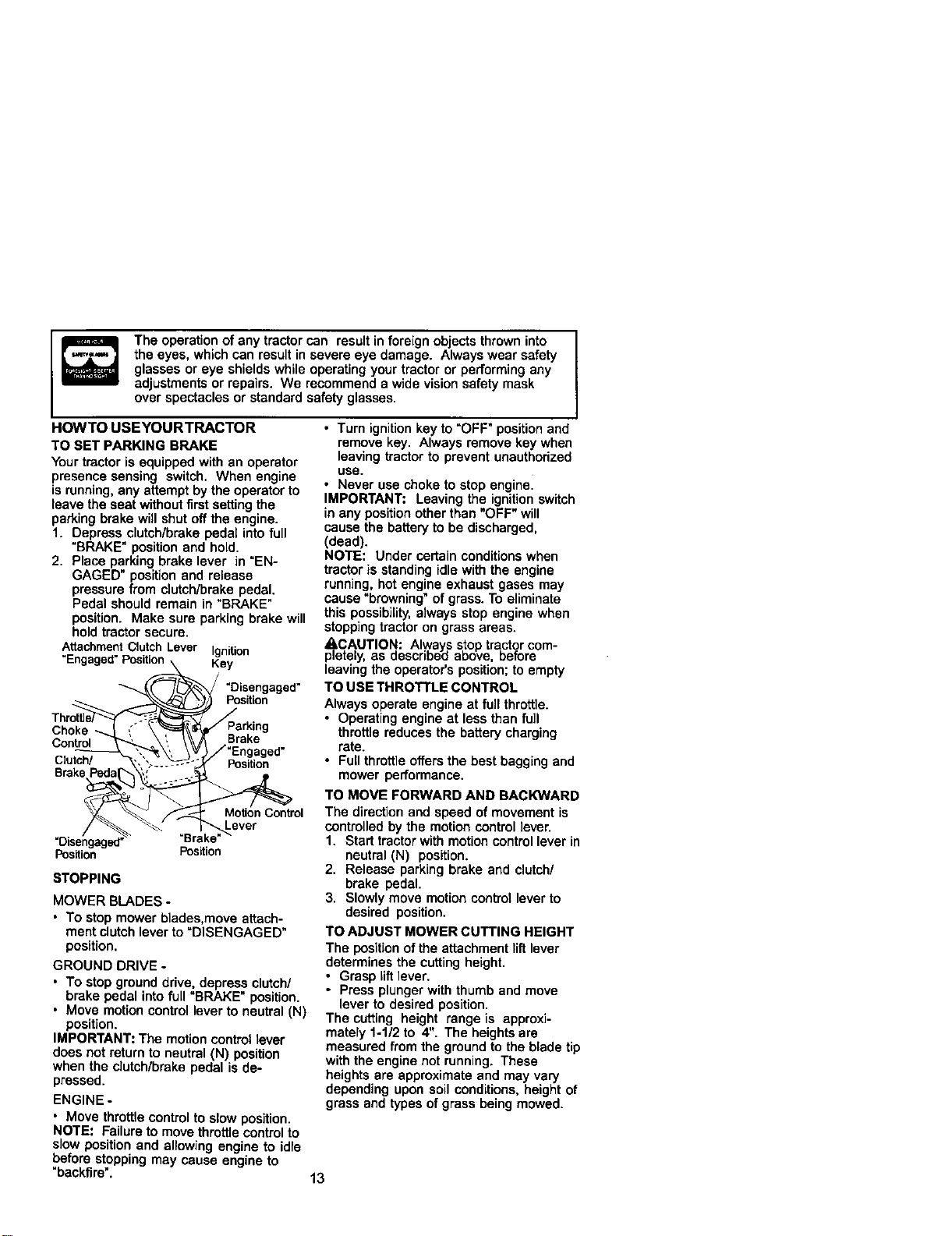
HOWTO USEYOURTRACTOR
TO SET PARKING BRAKE
Your tractor is equipped with an operator
presence sensing switch. When engine
is running,any attempt by the operator to
leave the seat without first setting the
parking brake will shut off the engine.
1. Depress clutch/brake pedal into full
"BRAKE" position and hold.
2. Place parking brake lever in "EN-
GAGED" position and release
pressure from clutch/brake pedal,
Pedal should remain in "BRAKE"
position. Make sure parking brake will
hold tractorsecure.
AttachmentClutchLever Ignition
"Engaged"Position Key
"Disengaged"
Position
Choke
Brake
Clutch/ Position
Brake
Control
Lever
=Disengaged' =Brake"
Position Position
STOPPING
MOWER BLADES -
• To stop mower blades,move attach-
ment clutchlever to "DISENGAGED"
position,
GROUND DRIVE -
• To stop ground drive, depress clutch/
brake pedal into full "BRAKE" position.
• Move motion control lever to neutral (N)
position.
IMPORTANT: The motion control lever
does not return to neutral (N) position
when the clutch/brake pedal is de-
pressed.
ENGINE -
• Move throttle control to slow position.
NOTE: Failure to movethrottlecontrol to
slow position and allowing engine to idle
before stopping may cause engine to
"backfire'.
• Turn ignition key to "OFF" position and
remove key. Always remove key when
leaving tractor to prevent unauthorized
use.
• Never use choke to stop engine.
IMPORTANT: Leavingthe ignitionswitch
in any positionother than "OFF" will
cause the battery to be discharged,
(dead).
NOTE: Under certain conditions when
tractor is standing idle with the engine
running, hot engine exhaust gases may
cause "browning" of grass. To eliminate
this possibility, always stop engine when
stopping tractor on grass areas.
_,CAUTION: Always stop tractor com-
pletely, as described above, before
leaving the operator's position; to empty
TO USE THROTTLE CONTROL
Always operate engine at full throttle.
• Operating engine at less than full
throttle reduces the battery charging
rate.
• Full throttle offers the best bagging and
mower performance.
TO MOVE FORWARD AND BACKWARD
The directionand speed of movement is
controlled by the motioncontrol lever.
1. Start tractor with motion control lever in
neutral (N) position.
2. Release parking brake and clutch/
brake pedal.
3. Slowly move motion control lever to
desired position.
TO ADJUST MOWER CUTTING HEIGHT
The positionof the attachment lift lever
determines the cutting height,
• Grasp lift lever.
• Press plungerwith thumb and move
lever to desired position,
The cutting height range is approxi-
mately 1-1/2 to 4", The heightsare
measured from the ground to the blade tip
with the engine not running. These
heights are approximate and may vary
depending upon soil conditions, height of
grass and types of grass being mowed,
13
• The average lawn should be cut to
approximately 2-1/2 inches during the
coolseason and to over 3 inches
dudng hot months. For healthier and
better lookinglawns, mow often and
after moderate growth.
• For best cutting performance, grass
over 6 inches in height should be
mowed twice. Make the first cut
relatively high;the second to desired
height.
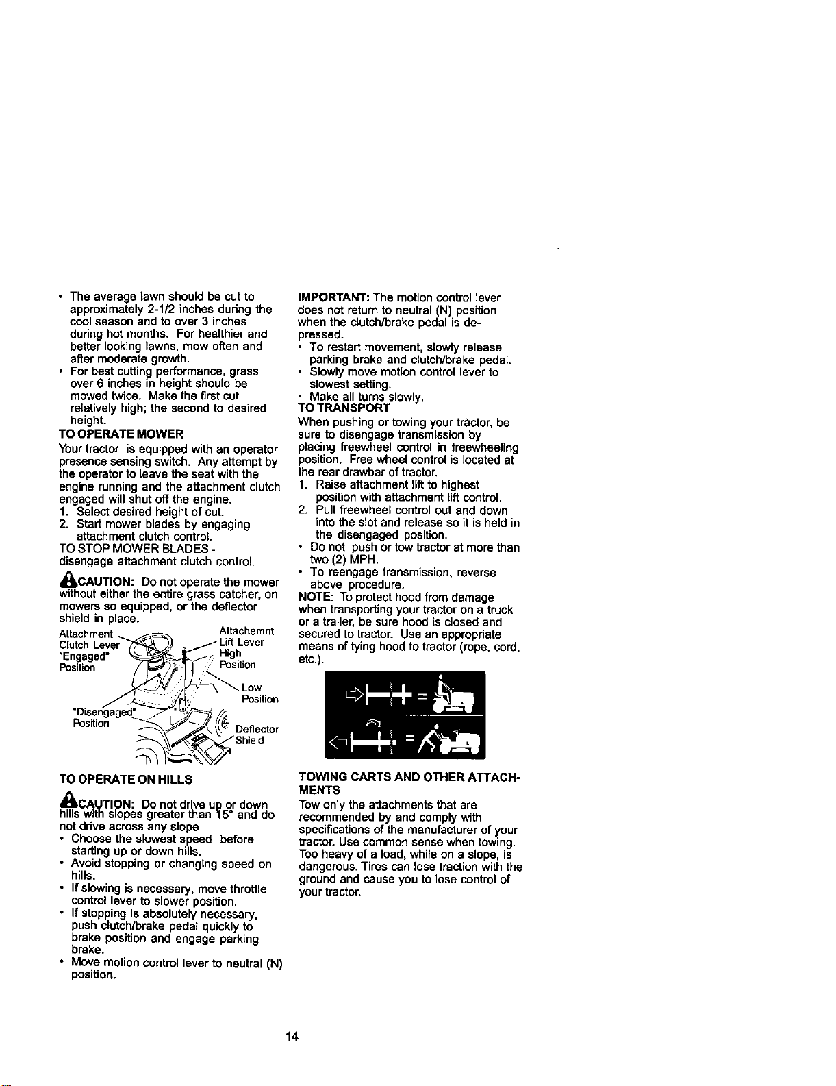
TO OPERATE MOWER
Your tractor is equipped with an operator
presence sensing switch. Any attempt by
the operator to leave the seat with the
engine runningand the attachment clutch
engaged will shut off the engine.
1. Select desired height of cut.
2. Start mower blades by engaging
attachment clutchcontrol.
TO STOP MOWER BLADES -
disengage attachment clutch control.
_,CAUTION: Do not operate the mower
withouteitherthe entire grass catcher, on
mowers so equipped, or the deflector
shield in place.
Attachment Attachemnt
"Engaged" , High
Position Position
IMPORTANT: The motioncontrol lever
does not return to neutral (N) position
when the clutch/brake pedal is de-
pressed.
• To restart movement, slowly release
parking brake and clutch/brake pedal.
• Slowly move motioncontrol lever to
slowest setting.
• Make all turns slowly.
TO TRANSPORT
When pushing or towingyour tractor,be
sure to disengage transmission by
placing freewheel control in freewheeling
position. Free wheel control islocated at
the rear drawbar of tractor.
1. Raise attachment lift to highest
position with attachment lift control.
2. Pull freewheel control out and down
into the slot and release so it is held in
the disengaged position.
• Do not push or tow tractor at more than
two (2) MPH.
• To reengage transmission, reverse
above procedure.
NOTE: To protect hood from damage
when transporting your tractor on a truck
or a trailer, be sure hood is closed and
secured to tractor. Use an appropriate
means of tying hood to tractor (rope, cord,
ete.).
Position
Position
Deflector
*'Shield
TO OPERATE ON HILLS
_I, CAUTION: Do notdrive up or down
hillswith slopes greater than 15° and do
notdrive across any slope,
• Choose the slowest speed before
starting up or down hills,
• Avoid stopping or changing speed on
hills.
• If slowing is necessary, move throttle
control lever to slower position.
• If stopping is absolutely necessary,
push clutch/brake pedal quickly to
brake position and engage parking
brake.
• Move motion control lever to neutral (N)
position.
TOWING CARTS AND OTHER ATTACH-
MENTS
Tow onlythe attachments that are
recommended by and comply with
specificationsof the manufacturer of your
tractor.Use common sense when towing.
Too heavy of a load, while on a slope, is
dangerous. Tires can lose tractionwith the
ground and cause you to lose control of
your tractor.
14
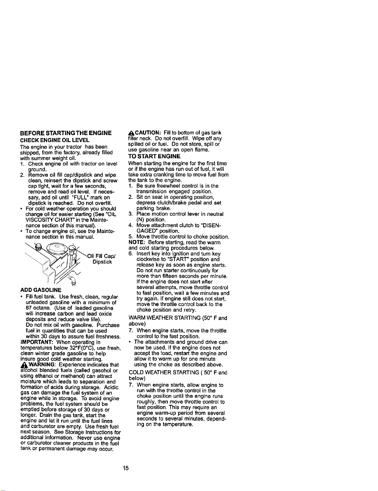
BEFORE STARTINGTHE ENGINE
CHECK ENGINE OIL LEVEL
The engine in your tractor has been
shipped, from the factory, already filled
with summer weight oil.
1. Check engine oil with tractor on level
ground.
2. Remove oil fill cap/dipstickand wipe
clean, reinsert the dipstick and screw
cap tight, wait for a few seconds,
remove and read oil level, if neces-
sary, add oil until "FULL" mark on
dipstick is reached. Do not overfill.
• For coldweather operationyou should
change oilfor easier starting(See =OIL
VISCOSITY CHART" inthe Mainte-
nance sectionof this manual).
• To change engine oil,see the Mainte-
nance section in thismanual
ADD GASOLINE
• Fillfueltank. Use fresh, clean, regular
unleaded gasoline with a minimum of
87 octane. (Use of leaded gasoline
wilt increase carbon and lead oxide
deposits and reduce valve life).
Do not mix oil with gasoline. Purchase
fuel in quantitiesthat can be used
within 30 days to assure fuel freshness.
IMPORTANT: When operating in
temperatures below 32°F(0°C), use fresh,
clean winter grade gasoline to help
insure good cold weather starting.
a_coWARNING: Experience indicatesthat
hol blended fuels (called gasohol or
using ethanol or methanol) can attract
moisture which leads to separation and
formation ofacids during storage. Acidic
gas can damage the fuel system of an
engine while in storage. To avoid engine
problems, the fuel system should be
emptied before storage of 30 days or
longer. Drain the gas tank, start the
engine and let it run until the fuel lines
and carburetor are empty. Use fresh fuel
next season. See Storage Instructions for
additional information. Never use engine
or carburetor cleaner products in the fuel
tank or permanent damage may occur.
_I, CAUTION: Fillto bottomof gas tank
filler neck. Do not overfill. Wipe off any
spilled oil or fuel. Do not store, spill or
use gasoline near an open flame.
TO START ENGINE
When starting the engine for the first time
or if the engine has run out of fuel, itwill
take extra cranking time to move fuel from
the tank to the engine.
1. Be sure freewheel control is in the
transmission engaged position_
2. Sit on seat in operating position,
depress clutch/breke pedal and set
parking brake.
3. Place motion control lever in neutral
(N) position.
4. Move attachment clutch to "DISEN-
GAGED" position.
5. Move throttle control to choke position.
NOTE: Before starting, read the warm
and cold starting procedures below.
6. Insert key into ignition and turn key
clockwise to "START" position and
release key as soon as engine starts.
Do not run starter continuously for
more than fifteen seconds per minute.
Ifthe engine does not start after
several attempts, move throttle control
to fast position, wait a few minutes and
try again, if engine still does not start,
move the throttle control back to the
choke position and retry.
WARM WEATHER STARTING (50° F and
above)
7. When engine starts, move the throttle
control to the fast position.
• The attachments and ground drive can
now be used. If the engine does not
accept the load, restart the engine and
allow it to warm up for one minute
using the choke as described above.
COLD WEATHER STARTING ( 50° F and
below)
7. When engine starts, allow engine to
run with the throttle control in the
choke position until the engine runs
roughly, then move throttle controlto
fast position. This may require an
engine warm-up period from several
seconds to several minutes, depend-
ing on the temperature.
15
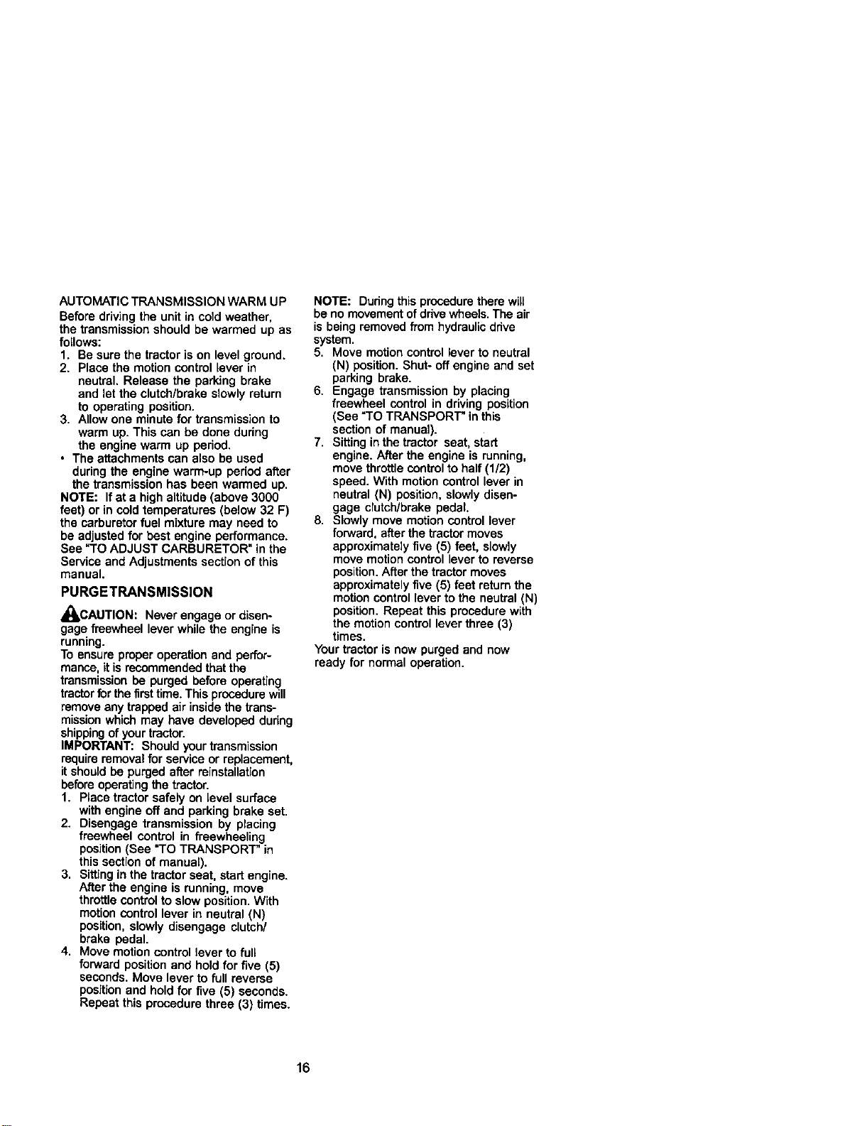
AUTOMATIC TRANSMISSION WARM UP
Before driving the unit in cold weather,
the transmission should be warmed up as
follows:
1. Be sure the tractor is on level ground.
2. Place the motion control lever in
neutral. Release the parking brake
and let the clutch/brake slowly return
to operating position.
3. Allow one minute for transmission to
warm up. This can be done dudng
the engine warm up period.
• The attachments can also be used
duringthe engine warm-up period after
the transmission has been warmed up.
NOTE: If at a high altitude(above 3000
feet) or in cold temperatures (below 32 F)
the carburetor fuel mixture may need to
be adjusted for best engine performance.
See "TO ADJUST CARBURETOR" in the
Service and Adjustments section of this
manual.
PURGETRANSMISSION
_CAUTION: Never engage or disen-
gage freewheel lever while the engine is
running.
To ensure proper operation and perfor-
mance, it is recommendedthat the
transmissionbe purged before operating
tractorfor the flint time. This procedurewill
removeany trapped air inside the trans-
missionwhich may have developed during
shippingof your tractor.
IMPORTANT: Should yourtransmission
requireremoval for serviceor replacement,
it shouldbe purged after reinstallation
before operatingthe tractor.
1. Placa tractor safely on level surface
with engine off and parking brake set.
2. Disengage transmission by placing
freewheel control in freewheeling
position(See "TO TRANSPORT" in
this section of manual).
3. Sitting in the tractor seat, start engine.
After the engine is running, move
throttle control to slow position. With
motion control lever in neutral (N)
position, slowly disengage clutch/
brake pedal.
4. Move motion control lever to full
forward position and hold for five (5)
seconds. Move lever to full reverse
position end hold for five (5) seconds.
Repeat this procedure three (3) times.
NOTE: Duringthis procedure there will
be no movement ofdrive wheels. The air
is being removed from hydraulic ddve
system.
5. Move motion control lever to neutral
(N) position. Shut- off engine and set
parking brake.
6. Engage transmission by placing
freewheel control in driving position
(See "TO TRANSPORT" in this
section of manual).
7. Sitting in the tractor seat, start
engine. After the engine is running,
move throttle control to half (1/2)
speed. With motion control lever in
neutral (N) position, slowly disen-
gage clutch/brake pedal.
8. Slowly move motion control lever
forward, after the tractor moves
approximately five (5) feet, slowly
move motion control lever to reverse
position. After the tractor moves
approximately five (5) feet return the
motion control lever to the neutral (N)
position. Repeat this procedure with
the motioncontrol lever three (3)
times.
Your tractoris now purged and now
ready for normal operation.
16
MOWlNGTIPS
• Mower should be properly leveled for
bestmowing performance. See "TO
LEVEL MOWER HOUSING" in the
Service and Adjustmentssection of
this manual.
• The left hand side of mower should be
usedfor trimming.
• Drive so that clippings are discharged
onto the area that has been cut. Have
the cut area to the rightof the tractor.
This will result in a more even distribu-
tion of clippingsand more uniform
cutting.
• When mowing large areas, start by
turningto the rightso that clippings will
discharge away from shrubs, fences,
driveways, etc. After one or two
rounds, mow in the opposite direction
making left hand turns until finished.
• If grass is extremely tall, it should be
mowed twice to reduce load end
possiblefire hazard from dried
clippings. Make first cut relatively
high;the second to the desired height.
• Do notmow grass when it iswet. Wet
grass will plug mower and leave
undesirable dumps. Allowgrass to
dry before mowing.
• Always operate engine at full throttle
when mowing to assure better mowing
performance and proper discharge of
material. Regulate ground speed by
selecting a low enough gear to give
the mower cuttingperformance as well
as the qualityof cut desired.
• When operating attachments, select a
ground speed that will suit the terrain
and give best performance of the
attachment being used.
MULCHING MOWlNGTIPS
IMPORTANT: For best performance,
keep mower housing free of built-up
grass and trash. Clean after each use.
• The special mulching blade will racut
the grass clippingsmany times and
reduce them in size so that as they fall
onto the lawn they will disperse into the
grass and not be noticed. Also, the
mulched grass will biodegrade quickly
to provide nutrientsfor the lawn.
Always mulch with your highest engine
(blade) speed as this will provide the
best recutting action of the blades.
• Avoid cuttingyour lawn when it is wet.
Wet grass tends to form clumps and
interferes with the mulchingaction.
The besttime to mow your lawn isthe
eady afternoon. At this time the grass
has dried and the newly cut area will
notbe exposed to the direct sun.
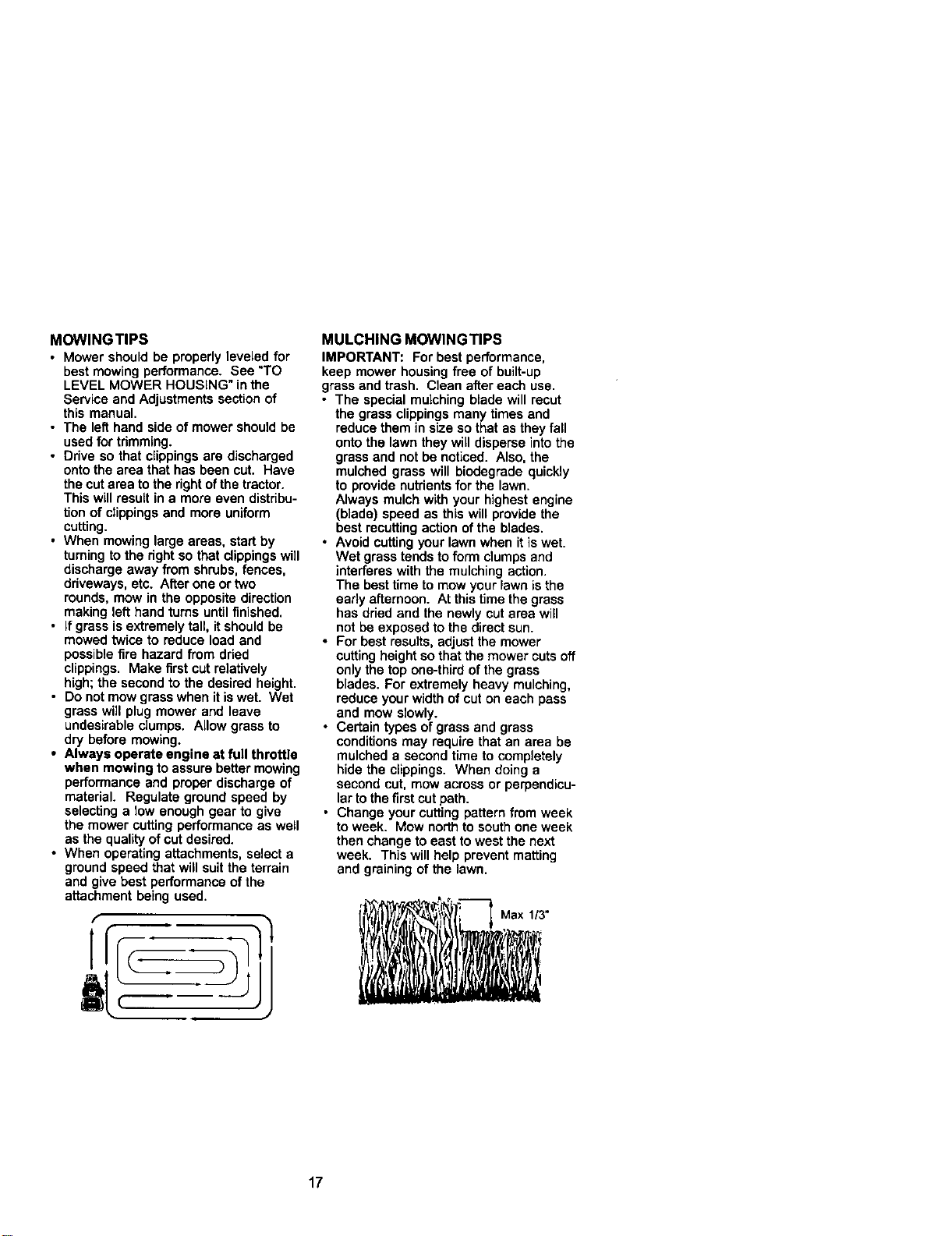
• For best results, adjust the mower
cuttingheight so that the mower cuts off
only the top one-third of the grass
blades. For extremely heavy mulching,
reduce your width of cut on each pass
and mow slowly.
• Certain types ofgrass and grass
conditionsmay require that an area be
mulched a second time to completely
hide the clippings. When doing a
second cut, mow across or perpendicu-
larto the first cut path.
• Change your cutting pattern from week
toweek. Mow north to south one week
then change to east to west the next
week. This will help prevent matting
and graining of the lawn.
Max 113"
17
GENERAL RECOMMENDATIONS
The warrantyon thistractor does not
cover itemsthat have been subjected to
operatorabuse or negligence. To receive
full value fromthe warranty,operator must
maintain tractor as instructedin this
manual.
Some adjustmentswill need to be made
periodically to propedy maintain your
tractor.
All adjustmentsin the Service and
Adjustments section ofthis manual should
be checked at least once each season.
• Once a year you should replace the
spark plug, clean or replace air filter,
and checkblades and belts forwear. A
new spark plug and clean air filter
assure proper air-fuel mixtureand help
your engine run better and last longer.
BEFORE EACH USE
1. Check engine oil level.
2. Check brake operation.
3. Check tire pressure.
4. Check operator presence and
interlock systems for proper opera-
tion.
5. Check for loose fasteners.
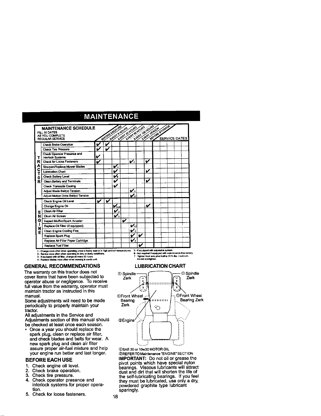
LUBRICATION CHART
@Spindle_ f'_ -- @Spindle
Zerk i'_: Zerk
/
@FrontWheel ,-. /
Beadng _ --".......
@Engine,]-_,,,"
@SAE 30 or 10w30 MOTOR OIL
@REFERTO Maintenance "ENGINE" SECTION
IMPORTANT: Do not oil or grease the
pivot points which have special nylon
bearings. Viscous lubricantswill attract
dust and dirtthat will shorten the lifeof
the self-lubricating]bearings. If you feel
they must be lubricated, use only a dry,
powdered graphite type lubricant
sparingly.
\
)FrontWheel
Boadng Zerk
18

TRACTOR
Always observe safety rules when
performing any maintenance.
BRAKE OPERATION
Iftractor requires more than six (6) feet
stopping distance at high speed in
highest gear, then brake must be
adjusted. (See =TOADJUST BRAKE" in
the Service and Adjustments sectionof
this manual),
TIRES
• Maintain proper air pressure in all tires
(See =PRODUCT SPECIFICATIONS"
section of this manual).
• Keep tires free of gasoline, oil, or
insect control chemicals which can
harm rubber.
• Avoid stumps, stones, deep ruts, sharp
objects and other hazards that may
cause tire damage.
NOTE: To seal tire punctures and
prevent fiattires due to slow leaks, tire
sealant may be purchased from your
local parts dealer. Tire sealant also
prevents tire dry rotand corrosion.
OPERATOR PRESENCE SYSTEM
Be sure operator presence and interlock
systemsare working properly. If your
tractor does not function as described,
repair the problem immediately.
• The engine should not start unless the
clutch/brake pedal is fully depressed
and attachement clutchcontrol is in
the disengaged position.
• When the engine is running, any
attempt bythe operator to leave the
seat withoutfirst settingthe parking
brake should shut off the engine.
• When the engine is running and the
attachment clutch is engaged, any
attempt bythe operator to leave the
seat should shut off the engine.
• The attachment clutch should never
operate unless the operator is in the
seat.
BLADE CARE
For best results mower blades must be
kept sharp. Replace bent or damaged
blades.
BLADE REMOVAL
1. Raise mower to highest positionto
allow access to blades.
2. Remove hex bolt, lock washer and
flat washer securing blade.
3. Install new or resharpened blade with
trailing edge up towards deck as
shown.
IMPORTANT: To ensure proper assembly,
center hole in blade must align with star
on mandrel assembly.
4. Reassemble hex bolt, lock washer
and fiat washer in exact order as
shown.
5. Tighten bolt securely (27-35 Ft, Lbs,
torque).
IMPORTANT: Blade bolt isgrade 8 heat
treated,
TrailingEdgeUp MandrelAssembly
_._ Blade Center/_,_/_.
.atWasher\
_--'-Hex Bolt(Grade)_'_-_,
*A Grade8heat treatedboltcanbe identified
by sixlinesonthebolthead.
TO SHARPEN BLADE
NOTE: We do not recommend sharpen-
ing blade - butif you do, be sure the
blade is balanced.
Care should be taken to keep the blade
balanced. An unbalanced blade will
cause excessive vibration and eventual
damage to mower and engine.
• The blade can be sharpened with a file
or on a grindingwheel. Do not attempt
to sharpen while on the mower.
• To check blade balance, you will need
a 5/8" diameter steel bolt, pin, or a cone
balancer. (When using a cone bal-
ancer, follow the instructions supplied
with balancer.)
NOTE: Do not use a nail for balancing
blade. The lobes of the center hole may
appear to be centered, butare not.
• Slide blade on to an anthreaded
portion of the steel bolt or pin and hold
the boltor pin parallel with the ground.
If blade is balanced, it should remain in
a horizontal position. If either end of
the blade moves downward, sharpen
the heavy end untilthe blade is
balanced.
/ /
, /
Blade
5/8"
Center J
BATTERY
Your tractorhas a battery charging system
which is sufficientfor normal use. How-
ever, pedodic charging ofthe battery with
an automotive charger will extend its life.
19
• Keep batteryand terminals clean.
• Keep batteryboltstight.
• Keep small vent holes open.
• Recharge at 6-10 amperes for 1 hour.
NOTE: The originalequipment batteryon
yourtractoris maintenance free. Do not
attempttoopen or remove caps or covers.
Addingor checkinglevel of electrolyte is
notnecessary.
TO CLEAN BATTERY AND TERMINALS
Corrosionand dirton the batteryand
terminalscan cause the batteryto "leak"
power.
1. Open batterybox door.
2. DisconnectBLACK batterycable first
then RED batterycable and remove
batteryfrom tractor.
3, Rinse the batterywith plainwater and
dry.
4. Clean terminalsand batterycable ends
with wire brush untilbright.
5. Coat terminalswith grease or petro-
leumjelly,
6. Reinstall battery (See "REPLACING
BATTERY" in the SERVICE AND
ADJUSTMENTS sectionof this
manual).
V-BELTS
Check V-beltsfor deteriorationand wear
after 100 hours ofoperation and replace if
necessary,The beltsare not adjustable.
Replace belts ifthey begin to slipfrom
wear.
TRANSAXLE COOLING
The transmissionfan and coolingfins
shouldbe kept clean to assure proper
cooling.
Do not attempt toclean fan or transmission
whiteengine is runningor while the
transmissionis hot,To prevent possible
damage to seals, do not use hlgh pressure
water or steam toclean transaxle.
• Inspect coolingtan to be sure fan blades
are intact and clean.
• Inspectcoolingfins for dirt,grass
clippingsand other materials. To
preventdamage to seals, do not use
compressed air or highpressure sprayer
toclean coolingfins.
TRANSAXLE PUMP FLUID
The trensaxle was sealed at the factory
and fluid maintenance is not requiredfor
the lifeofthe trensaxle. Should the
trensaxle ever leak or require servicing,
contactyour nearest authorized service
center/department.
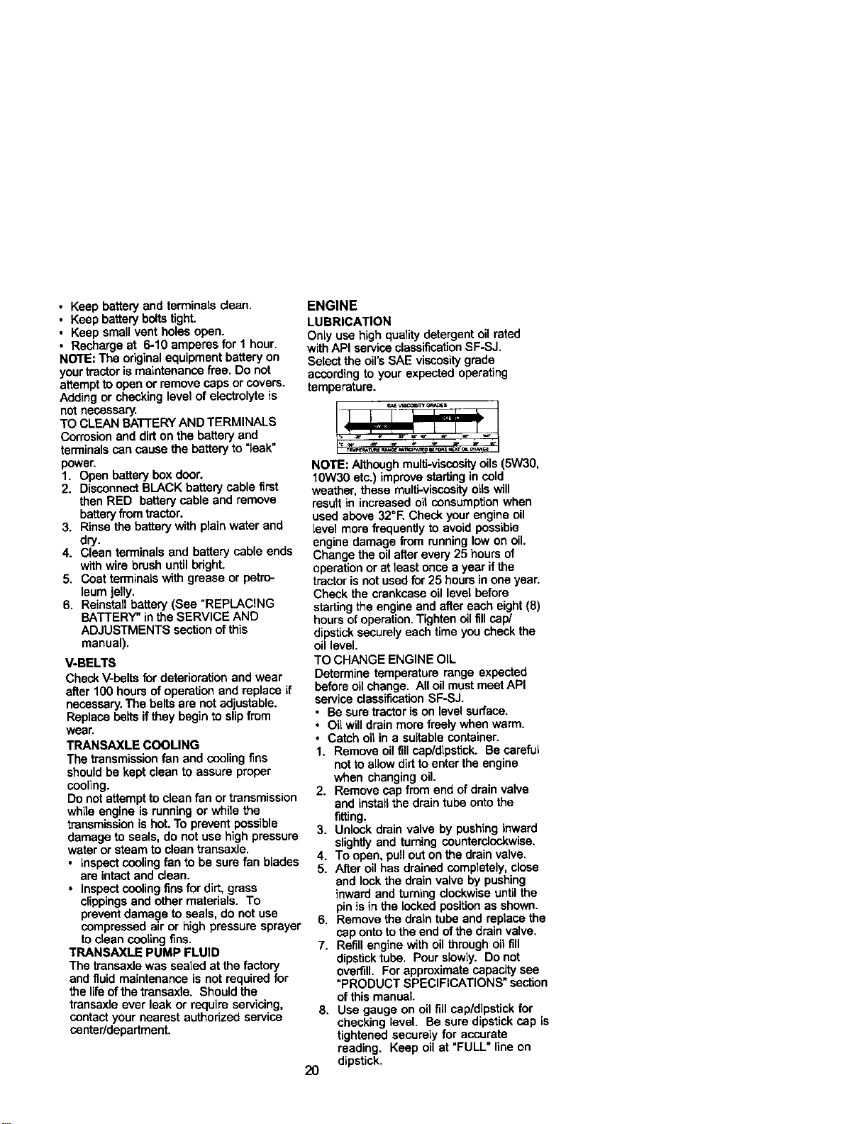
ENGINE
LUBRICATION
Only use highqualitydetergent oil rated
withAPI service classificationSF-SJ,
Selectthe oil'sSAE viscositygrade
accordingto your expected operating
temperature.
NOTE: Althoughmulti-viscosity oils(5W30,
lOW30 etc.) improve startingin cold
weather, these multi-viscosityoilswill
resultin increased oil censumpfion when
used above 32°E Check your engine oil
level more frequentlyto avoid possible
engine damage from runninglow on oil,
Change the oilafter every 25 hours of
operationor at least once a year if the
tractoris not usedfor 25 hours inone year.
Check the crankcase oil level before
startingthe engine and after each eight(8)
hoursof operation.Tighten oilfill cap/
dipsticksecurelyeach time you checkthe
oil level.
TO CHANGE ENGINE OIL
Determine temperature range expected
before oilchange. All oil mustmeet API
serviceclassificationSF-SJ.
• Be sure tractoris on levelsurface.
• Oilwill drainmore freely when warm.
• Catch oil in a suitablecontainer.
1. Remove oil fill cap/dipstick. Be careful
notto allowdirtto enter the engine
when changingoil.
2. Remove capfrom end of drain valve
and installthe drain tube onto the
fitting.
3. Unlockdrain valve by pushing inward
slightlyand turningcounterclockwise.
4. To open, pull outonthe drainvalve.
5. After oil has drained completely,close
and lock the drain valve by pushing
inward and turningclockwiseuntilthe
pinis in the locked positionas shown.
6. Remove the drain tube and replacathe
cap ontoto the end ofthe drainvalve,
7. Refillengine with oil through oil fill
dipsticktube, Pour slowly. Donot
overfill. For approximatecapacity see
"PRODUCT SPECIFICATIONS" section
of this manual.
8. Use gauge on oil fig cep/dipstick for
checking level. Be sure dipstickcap is
tightened securely for accurate
reading. Keep oil at "FULL • line on
dipstick,
2O
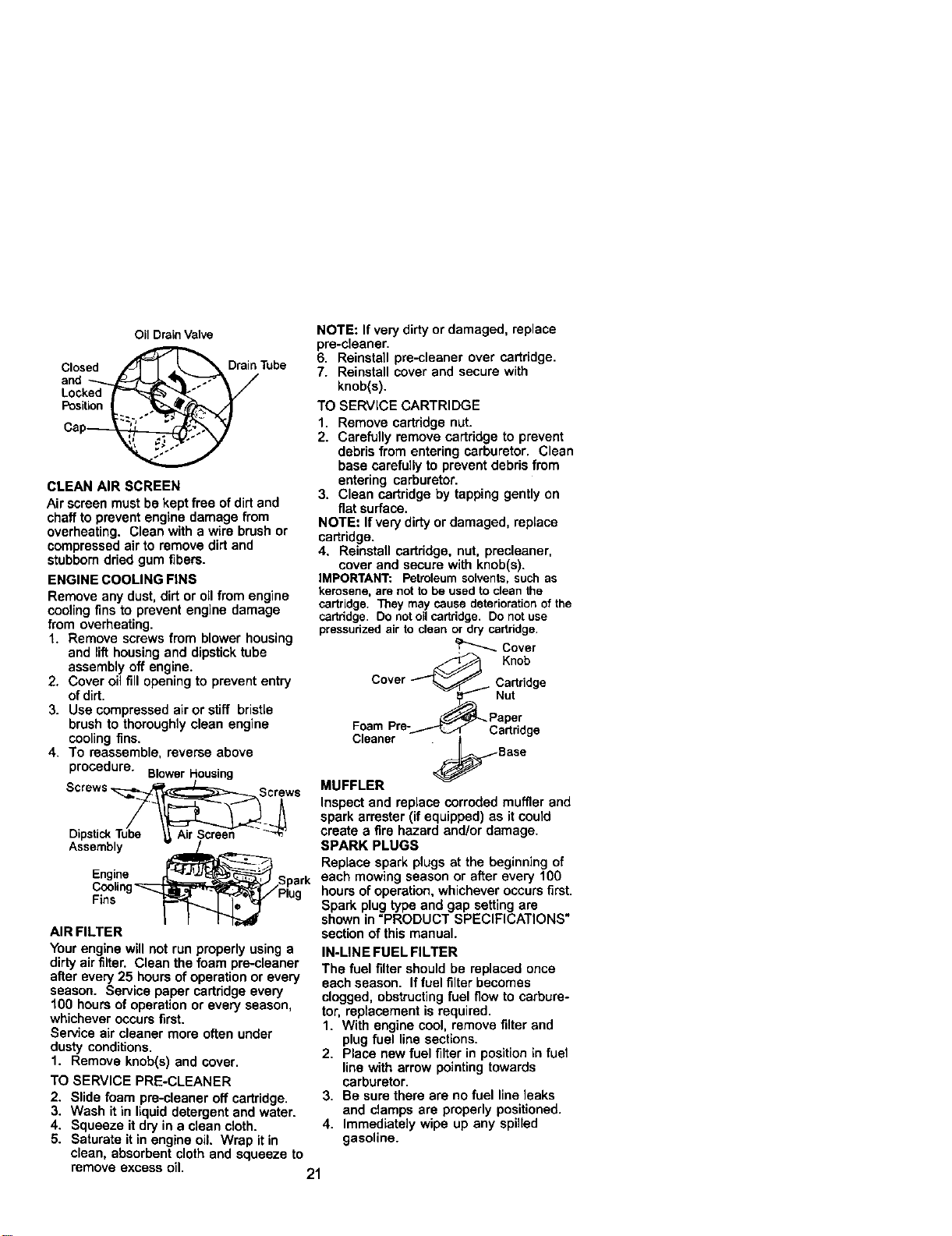
Oil Drain Valve
Closed _Drain Tube
i ,on
Cap_
CLEAN AIR SCREEN
Air screen must be kept free of dirtand
chaff to prevent engine damage from
overheating. Clean with a wire brush or
compressed air to remove dirt and
stubborndried gum fibers.
ENGINE COOLING FINS
Remove any dust, dirt or oil from engine
coolingfins to prevent engine damage
from overheating.
1. Remove screws from blower housing
and lifthousing and dipstick tube
assembly off engine.
2. Cover oil fill opening to prevent entry
of dirt.
3. Use compressed air or stiff bristle
brush to thoroughly clean engine
coolingfins.
4. To reassemble, reverse above
procedure. BlowerHousing
Screws_Screws
_ngiI. _ Spark
F_nslng_Plug
AIR FILTER
Yourengine will not run properly usinga
dirty air filter. Clean the foam pre-cleaner
after every 25 hours of operationor every
season. Service paper cartridge every
100 hours of operation or every season,
whichever occurs first.
Service air cleaner more often under
dusty conditions.
1. Remove knob(s) and cover.
TO SERVICE PRE-CLEANER
2. Slide foam pre-cleaner off cartridge.
3. Wash it in liquid detergent and water.
4. Squeeze it dry in a clean cloth.
5. Saturate itin engine oil. Wrap it in
clean, absorbent cloth and squeeze to
NOTE: If very dirty or damaged, replace
pre-cleaner.
6. Reinstall pre-cleaner over cartridge.
7. Reinstall cover and secure with
knob(s).
TO SERVICE CARTRIDGE
1. Remove cartddge nut.
2. Carefully remove cartridge to prevent
debris from entering carburetor. Clean
base carefully to prevent debris from
entering carburetor.
3. Clean cartridge by tapping gently on
fiat surface.
NOTE= Ifvery dirty or damaged, replace
cartridge.
4, Reinstall cartridge, nut, precleaner,
cover and secure with knob(s).
IMPORTANT: Petroleumsolvents,suchas
kerosene,are nottobe usedtocleanthe
cartridge.Theymaycausedeteriorationofthe
cartddge. Donotoilcartddge.Donotuse
pressudzedairto cleanor drycartddge.
Cover
' Knob
Cover _. Cartridge
Nut
oom
Cleaner
MUFFLER
Inspect and replace corroded muffler and
spark arrester (if equipped) as it could
create a fire hazard and/or damage.
SPARK PLUGS
Replace spark plugs at the beginning of
each mowing season or after every 100
hours of operation, whichever occurs first.
Spark plug type and gap setting are
shown in =PRODUCT SPECIFICATIONS"
section of this manual.
IN-LINE FUEL FILTER
The fuel filter should be replaced once
each season. If fuelfilter becomes
clogged, obstructingfuel flow to carbure-
tor, replacement is required.
1. With engine cool, remove filter and
plug fuel line sections.
2. Place new fuel filter in position in fuel
line with arrow pointingtowards
carburetor.
3. Be sure there are no fuel line leaks
and clamps are properly positioned.
4. Immediately wipe up any spilled
gasoline.
remove excess oil.
21
Clamp_Clamp
FuelFilter
CLEANING
Clean engine, battery, seat, finish, etc.
i of all matter.
foreign
Keep finished surfaces and wheels free
of all gasoline, oil, etc.
• Protect painted surfaces with automo-
tive type wax.
We do not recommend using a garden
hose to clean your tractor unless the
electrical system, muffler, air filter and
carburetor are covered to keep water out.
Water in engine can result in a shortened
engine life.
CAUTION: BEFORE PERFORMING ANY SERVICE OR ADJUSTMENTS:
1. Depress clutch/brake pedal fully and set parking brake.
2. Place motioncontrol lever in neutral (N) position.
3. Place attachment clutch in "DISENGAGED" position.
4. Turn ignition key "OFF" and remove key.
5. Make sure the blades and all moving parts have completely stopped.
6. Disconnect spark plug wire from spark plug and place wire where it cannot
come in contact with plug.
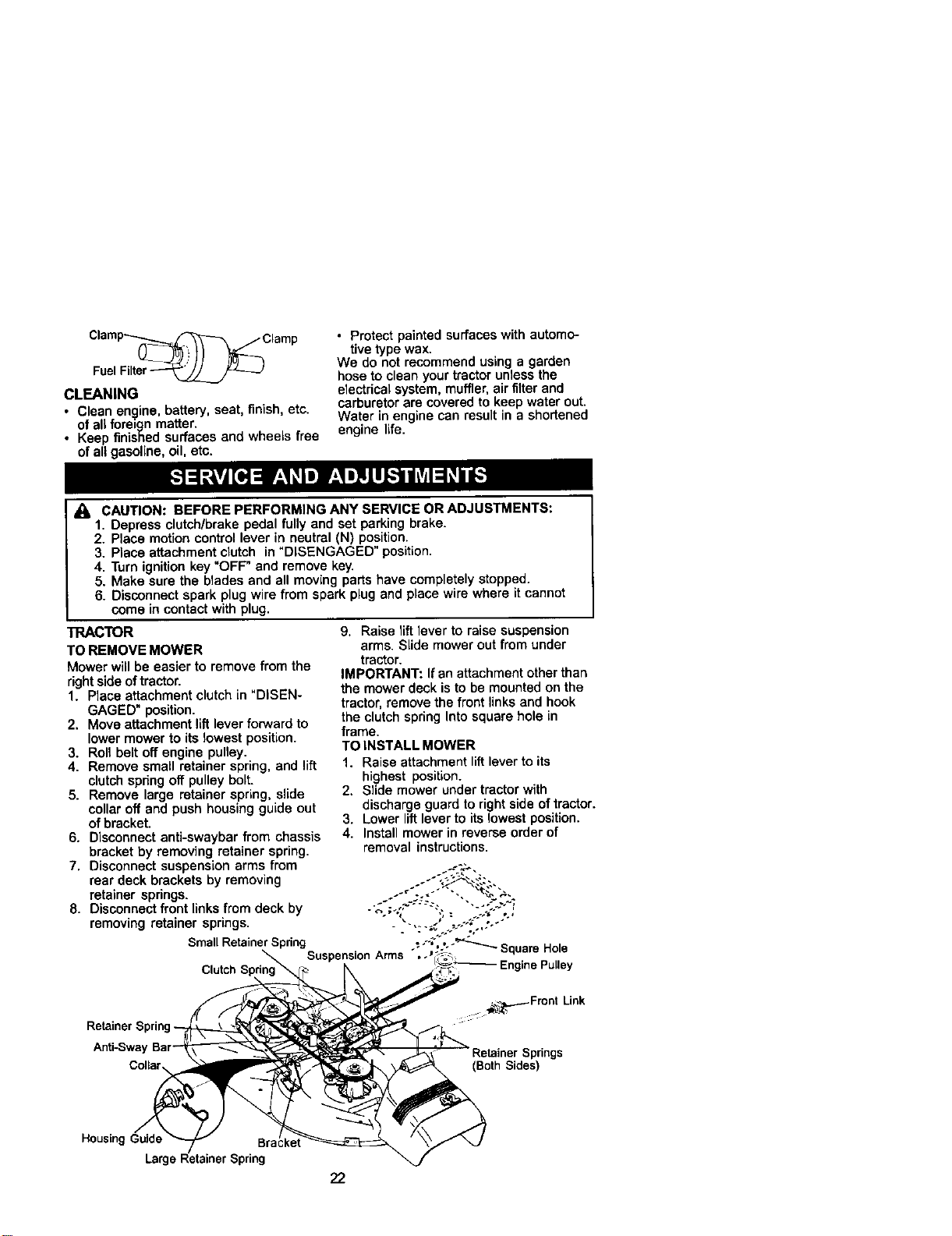
TRACTOR
TO REMOVE MOWER
Mower will be easier to remove from the
right side oftractor.
1. Place attachment clutchin "DISEN-
GAGED" position.
2. Move attachment lift lever forward to
lower mower to its lowest position.
3. Roll belt off engine pulley.
4. Remove small retainer spring, and lift
clutch spring off pulley bolt.
5. Remove large retainer spring, slide
collar off and push housing guide out
of bracket.
6. Disconnect anti-swaybar from chassis
bracket by removing retainer spring.
7. Disconnect suspension arms from
rear deck brackets by removing
retainer springs.
8. Disconnect front links from deck by
removing retainer springs.
Small RetainerSpdng
ClutchSpdng_
9. Raise lift lever to raise suspension
arms. Slide mower out from under
tractor.
IMPORTANT: If an attachment other than
the mower deck is to be mounted on the
tractor, remove the front links and hook
the clutch spring Into square hole in
frame.
TO INSTALL MOWER
1. Raise attachment lift lever to its
highest position.
2. Slide mower under tractor with
discharge guard to right side of tractor.
3. Lower lift lever to its lowest position.
4. Install mower in reverse order of
removal instructions.
Retain
Anti-Sway
Collar
:::::::: _._.-_Front Link
pdngs
(Both Sides)
HousingGuide
Larg_
22
TO LEVEL MOWER HOUSING
Ad ust the mower while tractor is parked
on eve ground or driveway. Make sure
tires are properly inflated (See "PROD-
UCT SPECIFICATIONS" section of this
manual). If tires are over or
underinfiated, you will not properly
adjustyour mower.
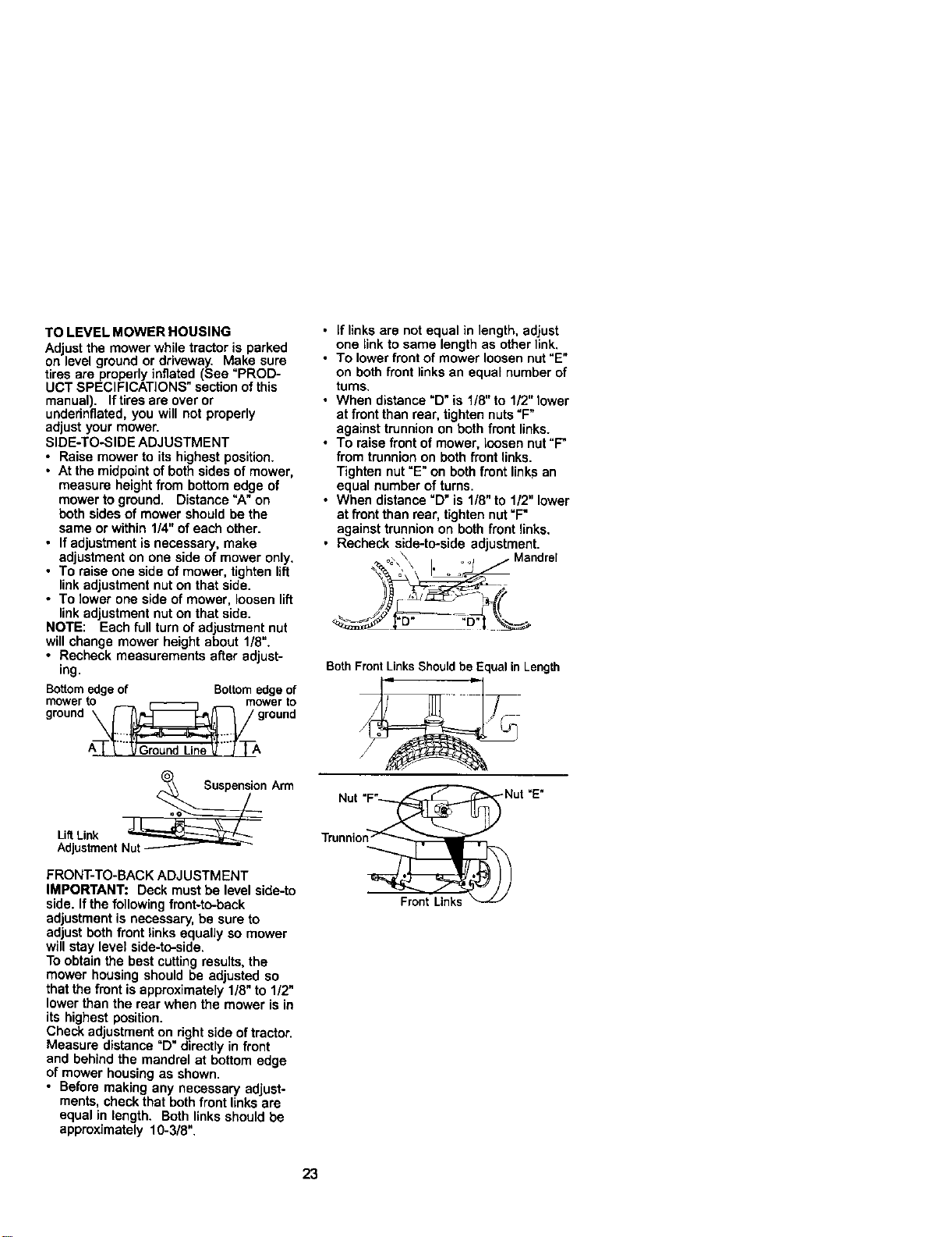
SIDE-TO-SIDE ADJUSTMENT
• Raise mower to its highest position.
• At the midpoint of both sides of mower,
measure height from bottom edge of
mower to ground, Distance "A" on
both sides of mower should be the
same or within 1/4" ofeach other.
• If adjustment is necessary, make
adjustment on one side of mower only,
• To raise one side of mower, tighten lift
linkadjustment nut on that side.
• To lower one side of mower, loosen lift
linkadjustment nut on that side.
NOTE: Each fullturn of adjustment nut
will change mower height about 1/8".
• Recheck measurements after adjust-
ing.
Bottomedgeof Bottomedgeof
mowerto mowerto
ground _ ground
7--A
FRONT-TO-BACK ADJUSTMENT
IMPORTANT: Deck must be levelside-to
side. If the followingfront-to-back
adjustment is necessary, be sure to
adjust both front links equally so mower
will stay level side-to-side.
To obtain the best cuttingresults, the
mower housing should be adjusted so
that the front isapproximately 1/8" to 1/2"
lower than the rear when the mower is in
its highest position.
Check adjustment on right side oftractor.
Measure distance "D"directly in front
and behind the mandrel at bottom edge
of mower housing as shown.
• Before making any necessary adjust-
ments, check that both front links are
equal in length. Both links should be
approximately 10-3/8",
• If links are not equal in length, adjust
one linkto same length as other link.
• To lower front of mower loosen nut"E"
on both front links an equal number of
turns.
• When distance "D" is 1/8" to 1/2" lower
at front than rear, tighten nuts"F"
against trunnionon both front links.
• To raise front of mower, loosen nut"F"
from trunnion on both front links.
Tighten nut "E" on both front links an
equal number of turns.
• When distance =D"is 1/8" to 1/2" lower
at front than rear, tighten nut =F"
against trunnion on both front links.
• Recheck side-to-side adjustment.
_ ._ Mandrel
BothFrontLinksShouldbe Equalin Length
FrontLinks
23
TO REPLACE MOWER BLADE DRIVE
BELT
The mower blade drive belt may be
replaced withouttools. Park the tractor on
level surface. Engage parking brake.
BELT REMOVAL -
1. Remove mower from tractor (See "TO
REMOVE MOWER" inthis section of
this manual).
2. Work belt off both mandrel pulleys and
idler pulleys.
3. Pull belt away from mower.
BELT INSTALLATION -
4. Install new belt in reverse order of
removal
5. Make sure belt is in all pulley grooves
and inside all belt guides.
6. Installmower in reverse order of
removal instructions.
Mandrel
Mandrel-
Pulley
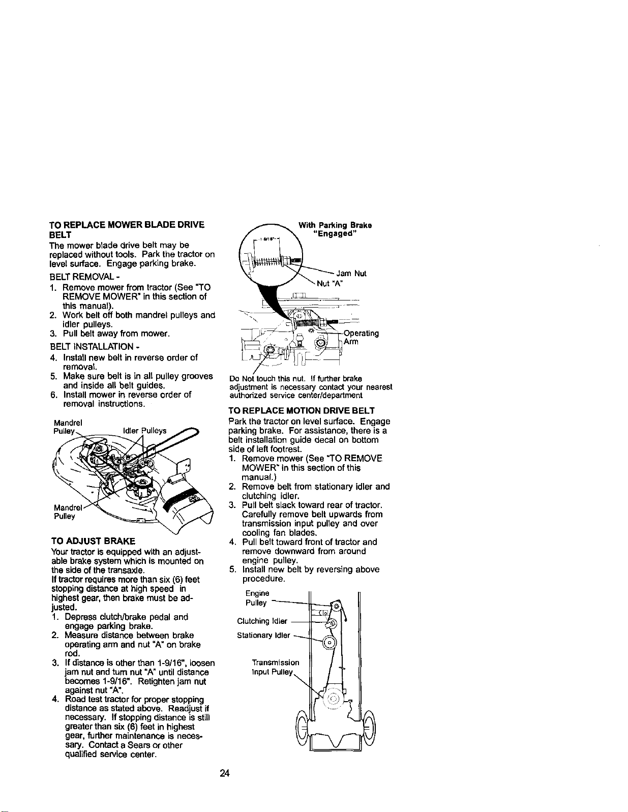
TO ADJUST BRAKE
Yourtractoris equippedwith an adjust-
able brake systemwhich is mounted on
the side ofthe transaxle.
Iftractorrequiresmorethan six (6) feet
stoppingdistance at high speed in
highestgear, then brake must be ad-
justed.
1. Depress clutch/brake pedal and
engage parking brake.
2. Measure distance between brake
operatingarm and nut "A" on brake
rod.
3. If distanceisother than 1-9/16", loosen
jam nut and tam nat "A"untildistance
becomes 1-9/16". Retightenjam nut
againstnut =A".
4. Road testtractorfor proper stopping
distanceas stated above. Readjust if
necessary. If stoppingdistance isstitl
greaterthan six (6) feet in highest
gear, furthermaintenance is neces-
sary. Contacta Sears or other
qualifiedservice center.
With Parking Brake
_ _ Jam Nut
Nut"A"
__Operating
_-_ Y_ C_J harm
Do Nottouchthis nut. If further brake
adjustmentis necessaP/contactyournearest
authorizedservicecenter/department
TO REPLACE MOTION DRIVE BELT
Park the tractor on level surface. Engage
parkingbrake. For assistance, there is a
belt installationguide decal on bottom
side ofleft footrest.
1. Remove mower (See "TO REMOVE
MOWER_ in this sectionof this
manual.)
2. Remove belt from stationary idtar and
clutching idler.
3. Pullbelt slack toward rear of tractor.
Carefully remove belt upwards from
transmission input pulley and over
coolingfan blades.
4. Pull belt toward front of tractor and
remove downward from around
engine pulley.
5. Install new belt by reversing above
procedure.
Engine
Pulley---------_
ClutchingIdler --
StationaryIdler
Transmission
InputPulley_
24
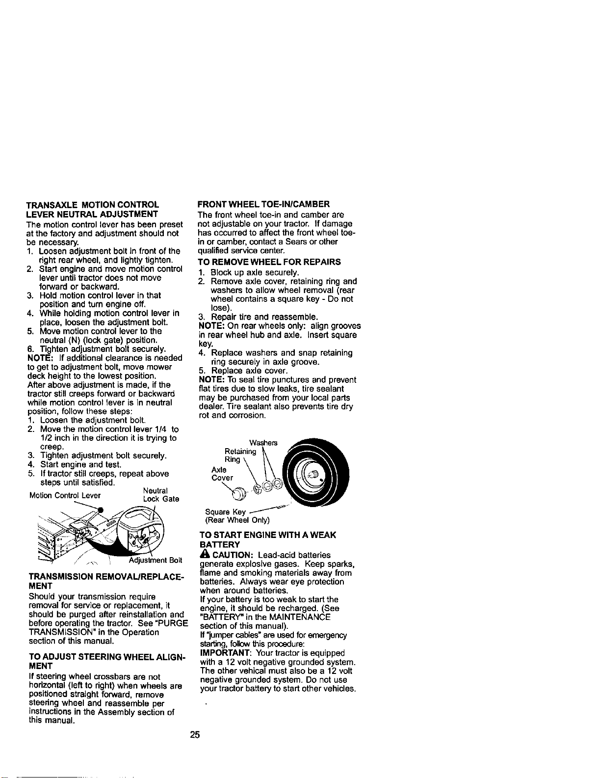
TRANSAXLE MOTION CONTROL
LEVER NEUTRAL ADJUSTMENT
The motion controllever has been preset
at the factoryand adjustment should not
be necessary.
1. Loosen adjustment bolt in front ofthe
right roar wheel, and lightlytighten.
2. Start engine and move motion control
lever untiltractor does not move
forward or backward.
3. Hold motion control lever in that
positionand turn engine off.
4. While holding motioncontrol lever in
place, loosen the adjustment bolt.
5, Move motioncontrol lever to the
neutral (N) (lock gate) position.
6. Tighten adjustment bolt securely.
NOTE: If additionalclearance is needed
to get to adjustment bolt, move mower
deck height to the lowest position.
After above adjustment is made, if the
tractor stillcreeps forward or backward
while motion control lever is in neutral
position, follow these steps:
1. Loosen the adjustment bolt.
2. Move the motion control lever 1/4 to
1/2 inch in the direction it is tryingto
creep.
3. Tighten adjustment bolt securely.
4. Start engine and test,
5. If tractorstillcreeps, repeat above
steps until satisfied.
Neutral
MotionControlLever LockGate
.... AdjustmentBolt
TRANSMISSION REMOVAL/REPLACE-
MENT
Should your transmission require
removal for service or replacement, it
should be purged after reinstallafion and
beforeoperating the tractor. See =PURGE
TRANSMISSION" in the Operation
section of this manual.
TO ADJUST STEERING WHEEL ALIGN-
MENT
If steeringwheel crossbars are not
horizontal (left to right) when wheels are
positioned straight forward, remove
steering wheel and reassemble per
instructionsin the Assembly section of
this manual.
FRONT WHEEL TOE-IN/CAMBER
The front wheel toe-in and camber are
not adjustable on your tractor. If damage
has occurred to affect the front wheel toe-
in or camber, contact aSears or other
qualifiedservice center.
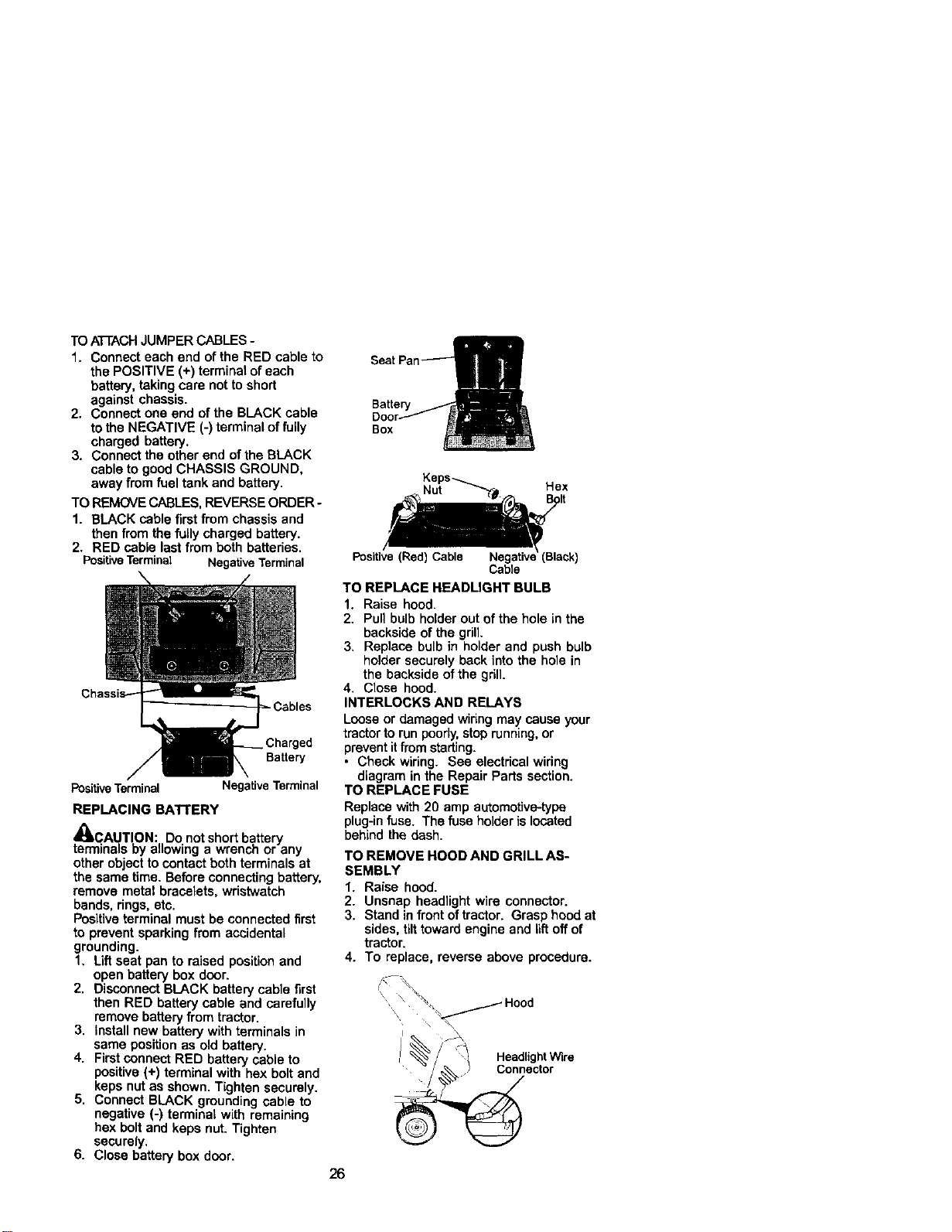
TO REMOVE WHEEL FOR REPAIRS
1. Block up axle securely.
2. Remove axle cover, retaining ring and
washers to allow wheel removal (roar
wheel contains a square key - Do not
lose).
3. Repair tire and reassemble.
NOTE: On roar wheels only: align grooves
in roarwheel hub and axle. Insert square
key.
4. Replace washers and snap retaining
ring securely in axle groove.
5, Replace axle cover.
NOTE: To seal tire punctures and prevent
fiat tires due to slow leaks, tire sealant
may be purchased from your local parts
dealer. Tire sealant also prevents tire dry
rot and corrosion.
Washers
Retaining __
, ing\
Cover \ L _l'_q, llllB
SquareKey
(Rear Wheel Only)
TO START ENGINE WITH A WEAK
BATTERY
/1= CAUTION: Lead-acid batteries
generate explosive gases. Keep sparks,
flame and smoking materials away from
batteries. Always wear eye protection
when around batteries.
Ifyour battery istoo weak to start the
engine, it should be recharged. (See
"BATTERY" in the MAINTENANCE
section of this manual).
If"jumper cables" are used for emergency
starting,follow this procedure:
IMPORTANT: Your tractor is equipped
with a 12 volt negative grounded system.
The other vehical must also be a 12 volt
negative grounded system. Do not use
your tractor battery to start other vehicles.
25
TO ATrACH JUMPER CABLES-
1. Connect each end of the RED cable to
the POSITIVE (+) terminal of each
battery, taking care not to short
against chassis.
2. Connect one end of the BLACK cable
to the NEGATIVE (-) terminal offully
charged battery.
3. Connect the other end of the BLACK
cable to good CHASSIS GROUND,
away from fuel tank and battery.
TO REMOVE CABLES,REVERSE ORDER-
1. BLACK cable firstfrom chassis and
then from the fullycharged battery.
2. RED cable lastfrom both batteries.
PositiveTerminal NegativeTerminal
PositiveTerminal
Negative Terminal
REPLACING BATTERY
_CAUTION: Do not short battery
terminals by allowing a wrench or any
other object to contact both terminals at
the same time. Before connectingbattery,
remove metal bracelets, wristwatch
bands, dngs, etc.
Positiveterminal must be connected first
to prevent sparking from accidental
grounding.
1. Lift seat pan to raised positionand
open battery box door.
2. Disconnect BLACK battery cable first
then RED battery cable and carefully
remove batteryfrom tractor.
3. Install new battery with terminals in
same position as old battery.
4. Firstconnect RED battery cable to
positive(+) terminal with hex bolt and
keps nutas shown. Tighten securely.
5. Connect BLACK grounding cable to
negative (-) terminal with remaining
hex bolt and keps nut. Tighten
securely.
6. Close battery box door.
Battery
Box
Positive (Red) Cable
Cable
TO REPLACE HEADLIGHT BULB
1. Raise hood.
2. Pull bulb holder out of the hole in the
backside ofthe grill.
3. Replace bulb in holder and push bulb
holder securely back intothe hole in
the backside of the grill.
4. Close hood.
INTERLOCKS AND RELAYS
Loose or damaged widng may cause your
tractorto runpoorly,stoprunning,or
prevent itfrom starting.
• Check wiring. See electricalwiring
diagram in the Repair Parts section.
TO REPLACE FUSE
Replace with 20 amp automofive-type
plug-infuse. The fuse holder is located
behind the dash.
TO REMOVE HOOD AND GRILL AS-
SEMBLY
1. Raise hood.
2. Unsnap headlight wire connector.
3. Stand infront of tractor. Grasp hood at
sides, tilttoward engine and lift off of
tractor.
4. To replace, reverse above procedure.
Headlight Wlre
Connector
26
ENGINE
Maintenance, repair, or replacement of
the emission control devices and sys-
tems, which are being done at the
customersexpense, may be performed
by any non-road engine repair establish-
ment or individual.Warranty repairs must
be performed by an authorized engine
manufacturer's service outlet.
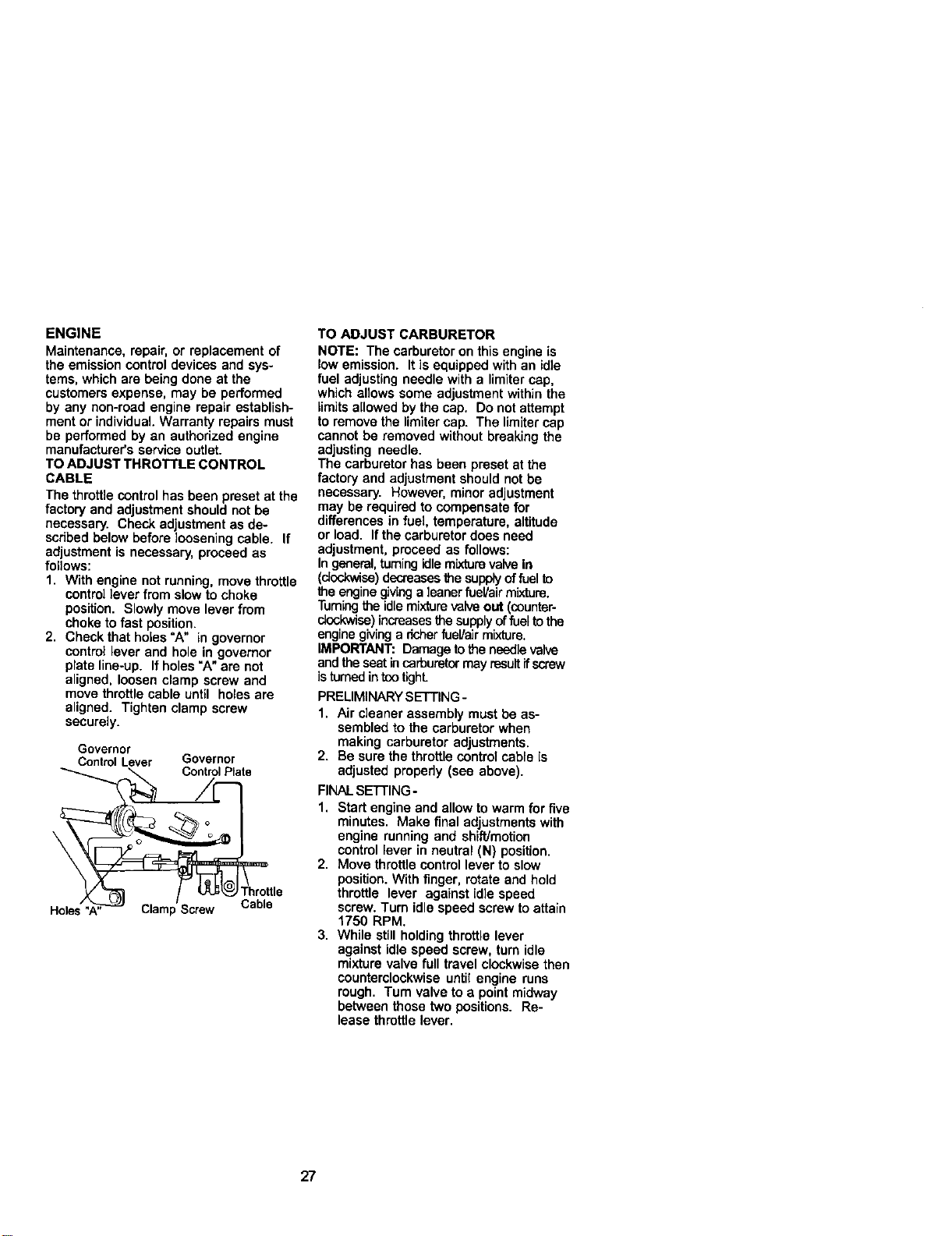
TO ADJUST THROTTLE CONTROL
CABLE
The throttlecontrol has been preset at the
factory and adjustment should not be
necessary. Check adjustment as de-
scribedbelow before loosening cable. If
adjustment is necessary, proceed as
follows:
1. With engine not running, move throttle
control lever from slow to choke
position. Slowly move lever from
choke to fast position.
2. Check that holes'A" in governor
control lever and hole in governor
plate line-up. If holes "A"ere not
aligned, loosen clamp screw and
move throttle cable until holes are
aligned. Tighten clamp screw
securely.
Governor
ContmlLever Governor
Control Plate
Holes Clamp Screw Cable
TO ADJUST CARBURETOR
NOTE: The carburetor on this engine is
low emission. It is equipped with an idle
fuel adjusting needle with a limiter cap,
which allows some adjustment within the
limitsallowed by the cap. Do not attempt
to remove the limitercap. The limiter cap
cannot be removed without breaking the
adjusting needle.
The carburetor has been preset at the
factory end adjustment should not be
necessary. However, minor adjustment
may be required to compensate for
differences in fuel, temperature, altitude
or load. Ifthe carburetor does need
adjustment, proceed as follows:
Ingeneral,turningidlemLxturevalvein
(_se) decreasesthe supplyof fuelto
the enginegivingaleaner fueVairmixture.
Turningthe idlemixture valveout (ceunter-
dcokwise) increases thesupplyoffuelto the
enginegivinga dcherfue!/air mixture.
IMPORTANT: Damage tothe needlevalve
and theseat incarburetormay resultifscrew
isfumed intootighL
PRELIMINARYSETTING -
1. Air cleaner assembly must be as-
sembled to the carburetor when
making carburetor adjustments.
2. Be sure the throttle control cable is
adjusted propedy (see above).
FINALSE'n'ING-
1. Start engine and allow to warm for five
minutes. Make final adjustments with
engine running and shift/motion
control lever in neutral (N) position.
2. Move throttle control lever to slow
position. With finger, rotate and hold
throttle lever against idle speed
screw. Turn idle speed screw to attain
1750 RPM.
3. While still holding throttle lever
against idle speed screw, turn idle
mixture valve full travel clockwise then
counterclockwise until engine runs
rough. Turn valve to a point midway
between those two positions. Re-
lease throttle lever.
27
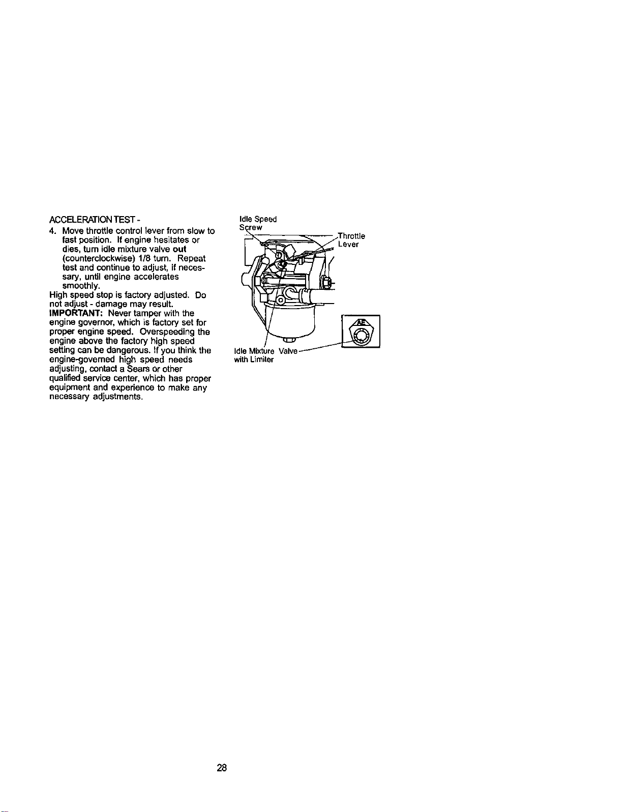
ACCELERATIONTEST -
4. Move throttle control fever from slow to
fast position. If engine hesitates or
dies, turnidle mixture valve out
(counterclockwise) 1/8 turn. Repeat
test and continueto adjust, if neces-
sary, until engine accelerates
smoothly.
High speed stop is factory adjusted. Do
not adjust- damage may result.
IMPORTANT: Never tamper with the
engine governor, which is factory set for
proper engine speed. Overspeeding the
engine above the factory high speed
setting can be dangerous. If you think the
engine-9overned high speed needs
adjusting,contact a Sears or other
qualifiedservice center, which has proper
equipment and experience to make any
necessary adjustments.
Idle Speed
S__.. /Thro_le
Lever
Idle Mixture Valve _
with Limiter
28
Immediately prepare your tractor for
storageat the end ofthe season or if the
tractor will not be used for 30 days or
more.
CAUTION: Never store the tractor
with gasoline in the tank inside a building
where fumes may reach an open flame or
spark. Allow the engine to cool before
storing in any enclosure.
TRACTOR
Remove mower from tractor for winter
storage. When mower is to be stored for
a period of time, clean it thoroughly,
remove all dirt, grease, leaves, etc. Store
in a clean, dry area.
1. Clean entire tractor (See =CLEANING"
in the Maintenance section of this
manual).
2. Inspect and replace belts, if necessary
(See belt replacement instructions in
the Service and Adjustments section
of this manual).
3. Lubricate as shown in the Mainte-
nance section of this manual.
4. Be sure that all nuts, bolts and screws
are securely fastened. Inspect moving
parts for damage, breakage and wear.
Replace if necessary.
5. Touch up all rusted or chipped paint
surfaces; sand lightly before painting.
BAnERY
• Fullycharge the battery for storage.
• After a period of time in storage, battery
may require recharging.
• To help prevent corrosion and power
leakage during long periods of storage,
battery cables should be disconnected
and battery cleaned thoroughly(see
"TO CLEAN BATTERY AND TERMI-
NALS" in the Maintenance section of
this manual).
• After cleaning, leave cables discon-
nected and place cables where they
cannot come in contactwith battery
terminals.
• Ifbattery is removed from tractor for
storage, do not store battery directly on
concrete or damp surfaces.
ENGINE
FUEL SYSTEM
IMPORTANT: It is important to prevent
gum deposites from forming in essential
fuel system parts such as carburetor,fuel
hose, or tank during storage.
Also, experiance indicates that alcohol
blended fuels (called gasohol or using
ethanol or methanol) can attract moisture
which leads to separation and formation
of acids during storage. Acidic gas can
damage the fuel system of and engine
while in storage.
1. Drainthe fuel tank.
2. Start the engine and let it run untilthe
fuel lines and carburetor are empty.
• Never use engine or carburetor cleaner
products in the fuel tank or permanent
damage may occur.
• Use fresh fuel next season.
NOTE: Fuel stabilizer isan acceptable
alternative in minimizing the formation of
fuel gum deposits during storage. Add
stabilizer to gasoline in fuel tank or
storage container. Always follow the mix
ratio found on stabilizer container. Run
engine at least 10 minutes after adding
stabilizer to allow the stabilizer to reach
the carburetor. Do not drainthe gas tank
and carburetor if using fuel stabilizer.
ENGINE OIL
Drain oil (with engine warm) and replace
with clean engine oil. (See "ENGINE" in
the Maintenance section of this manual).
CYLINDER(S)
1. Remove spark plug(s).
2. Pour one ounce of oil through spark
plug hole(s) into cyUnder(s).
3. Turn ignitionkey to "START" position
for a few secondsto distributeoil.
4. Replace with new spark plug(s).
OTHER
• Do not store gasoline from one season
to another.
• Replace your gasoline can if your can
startsto rust. Rust and/or dirtin your
gasoline will cause problems.
• If possible,store your tractor indoors
and cover it togive protectionfrom dust
and dirt.
• Cover your tractor with a suitable
protective coverthat does not retain
moisture. Do not use plastic. Plastic
cannot breathe which allows conden-
sation to form and will cause your
tractorto rust.
IMPORTANT: Never cover tractor while
engine and exhaust areas are stillwarm.
29
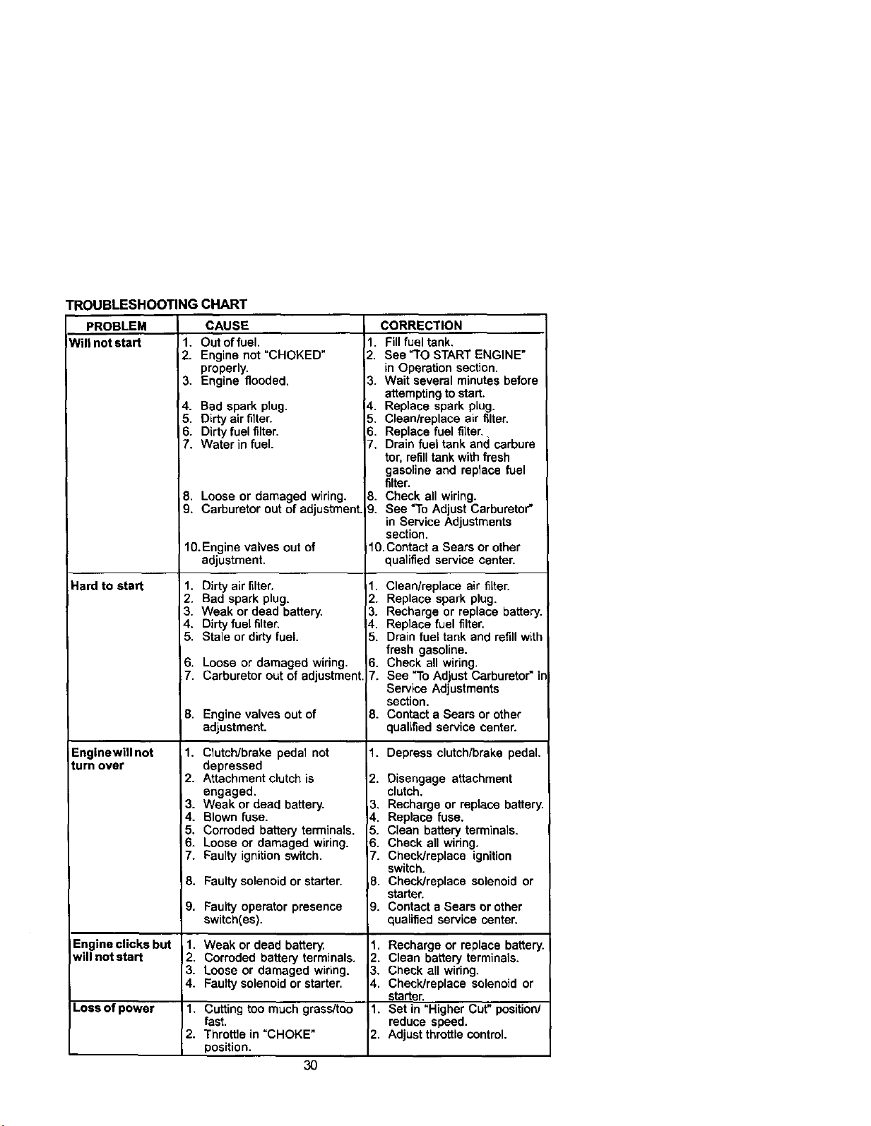
TROUBLESHOOTINGCHART
PROBLEM
Wiltnotstart 1.
2,
3.
4.
5,
6.
7.
Hard to start
Englnewill not
turn over
Engine clicks but
will not start
CAUSE
Out offuel.
Engine not "CHOKED"
properly.
Engine flooded.
Bad spark plug.
Dirty air filter.
Dirty fuel filter.
Water in fuel.
8. Loose or damaged wiring.
9. Carburetor out of adjustment.
10.Engine valves out of
adjustment.
1. Dirty air filter.
2. Bad spark plug.
3. Weak or dead battery.
4. Dirty fuel filter,
5. Stale or dirty fuel.
6. Loose or damaged wiring.
7. Carburetor out of adjustment
8. Engine valves out of
adjustment.
1. Clutch/brake pedal not
depressed
2. Attachment clutch is
engaged.
3. Weak or dead battery.
4. Blown fuse.
5. Corroded battery terminals.
6. Loose or damaged wiring.
7, Faulty ignition switch.
8. Faulty solenoid or starter.
9. Faulty operator presence
switch(es).
1. Weak or dead battery.
2. Corroded battery terminals.
3. Loose or damaged wiring.
4. Faulty solenoid or starter.
Loss of power 1. Cutting too much grass/too
fast.
2. Throttle in "CHOKE"
position.
3O
CORRECTION
1. Fill fuel tank.
2. See "TO START ENGINE"
in Operation secfion.
3. Wait several minutes before
attemptingto start.
4. Replace spark plug.
5. Clean/replace air filter.
6. Replace fuel filter..
7. Drain fuel tank and carbure
tor, refilltank withfresh
gasoline and replace fuel
filter.
8. Check all wiring.
9. See "To Adjust Carburetor"
in Service Adjustments
section.
10.Contact a Sears or other
qualified service center.
1. Clean/replace air filter.
2. Replace spark plug.
3. Recharge or replace battery.
4. Replace fuel filter.
5. Drain fuel tank and refill with
fresh gasoline.
I716:Check aU winng.
See "To Adjust Carburetor" in
Service Adjustments
section.
B. Contact a Sears or other
qualified service center.
1. Depress clutch/brake pedal.
2. Disengage attachment
clutch.
3, Recharge or replace battery.
4. Replace fuse.
5. Clean battery terminals.
6. Check all wiring,
7. Check/replace ignition
switch,
8. Check/replace solenoid or
starter.
9. Contact a Sears or other
qualified service center.
1. Recharge or replace battery.
2. Clean battery terminals.
3. Check all wiring,
4. Check/replace solenoid or
starter.
1. Set in "Higher Cut" position/
reduce speed.
2. Adjust throttle control.
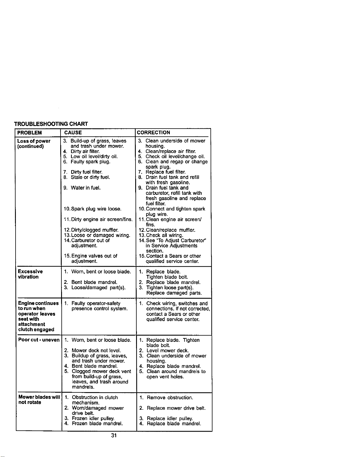
TROUBLESHOOTING CHART
PROBLEM
Loss of power
(continued)
Excessive
vibration
CAUSE
3. Build-up of grass, leaves
and trash under mower.
4. Dirty air filter.
5. Low oil level/dirty oil.
6. Faulty spark plug.
Engine continues
to run when
operator leaves
seat with
attachment
clutch engaged
Poorcut-uneven
Mowerbladeswill
notr_a_
7. Dirty fuel filte_
8. Stale or dirty fuel.
9. Waterin fuel.
1O.Spark plug wire loose.
11. Dirty engine air screen/fins.
12.Dirty/clogged muffler.
13.Loose or damaged wiring.
14.Carburetor out of
adjustment.
15. Engine valves outof
adjustment.
1. Worn, bent or loose blade.
2. Bent blade mandrel.
3. Loose/damaged part(s).
1. Faulty operator-safety
presence controlsystem.
1. Worn, bent or loose blade.
2. Mower deck not level.
3. Buildup of grass, leaves,
and trash under mower.
4. Bent blade mandrel.
5. Clogged mower deck vent
from build-up of grass,
leaves, and trash around
mandrels.
1. Obstruction in clutch
mechanism.
2. Worn/damaged mower
drive belt.
3. Frozen idler pulley.
4. Frozen blade mandrel.
CORRECTION
3. Clean underside of mower
housing.
4. Clean/replace air filter.
5. Check oil level/change oil.
6. Clean and regap or change
spark plug.
7. Replace fuel filter.
8. Drain fuel tank and refill
with fresh gasoline.
9. Drain fuel tank and
carburetor, refill tank with
fresh gasoline and replace
fuel filter.
10.Connect and tighten spark
plug wire.
11.Clean engine air screen/
fins.
12.Clean/replace muffler.
13.Check all wiring.
14.See =ToAdjust Carburetor"
in Service Adjustments
section.
I 15.Contact a Sears or other
qualified service center.
1. Replace blade.
Tighten blade bolt.
2. Replace blade mandrel.
3. Tighten loose part(s).
Replace damaged parts.
1. Check wiring, switches and
connections. If not corrected
contact a Sears or other
qualified service center.
1. Replace blade. Tighten
blade bolt.
2. Level mower deck.
3. Clean underside of mower
housing.
4. Replace blade mandrel.
5. Clean around mandrels to
open vent holes.
1. Remove obstruction.
2. Replace mower drive belt.
3. Replace idler pulley.
4. Replace blade mandrel.
31
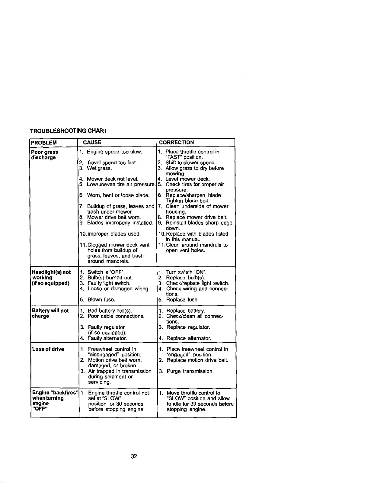
TROUBLESHOOTING CHART
PROBLEM
Poor grass
discharge
Headlight(s) not
working
(if so equipped)
Battery will not
charge
CAUSE CORRECTION
1. Engine speed too slow.
2. Travel speed too fast.
3. Wet grass.
4. Mower deck not level.
5. Low/uneven tire air pressure
,6. Worn, bent or loose blade.
7. Buildup of grass, leaves and
trash under mower.
8. Mower drive belt worn.
_. Blades improperly installed.
10.Improper blades used,
11.Clogged mower deck vent
holes from buildup of
grass, leaves, and trash
around mandrels.
1. Switch is"OFF".
2. Bulb(s) burned out.
3. Faulty light switch.
4. Loose or damaged wiring.
5. Blown fuse.
1. Bad battery cell(s).
2. Poor cable connections.
3. Faulty regulator
(if so equipped).
4. Faulty alternator.
Loss of drive 1.
2.
3.
Engine "backfires" 1.
whenturning
engine
"OFF"
Freewheel control in
"disengaged" position.
Motion drive belt worn,
damaged, or broken.
Air trapped in transmission
during shipment or
servtcing.
1. Place throttle control in
"FAST" position.
2. Shift to slower speed.
_3. Allow grass to dry before
I mowing.
4. Level mower deck.
5. Check tires for proper air
pressure.
6. Replace/sharpen blade.
Tighten blade bolt.
7. Clean underside of mower
housing.
B, Replace mower drive belt.
9, Reinstall blades sharp edge
down.
1O.RepLacewith blades listed
in this manual
11.Clean around mandrels to
open vent holes.
1. Turn switch "ON".
2. Replace bulb(s).
3. Check]replace light switch.
4. Check wiring and connec-
tions.
5. Replace fuse.
1. Replace battery.
2. Check/clean all connec-
tions.
3. Replace regulator.
4. Replace alternator.
1. Place freewheel control in
"engaged" position.
2. Replace motion drive belt.
3. Purge transmission.
Engine throttle control not 1. Move throttle control to
setat "SLOW" "SLOW" position and allow
position for 30 seconds to idle for 30 seconds before
before stopping engine, stopping engine.
32
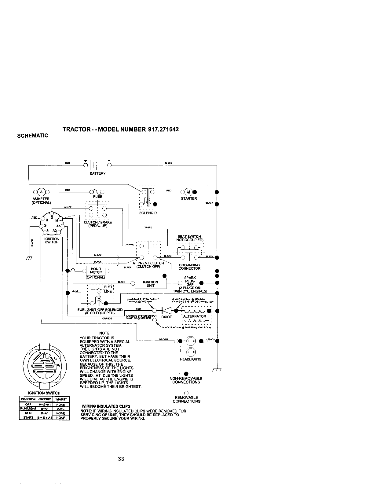
TRACTOR..MODELNUMBER917.271642
SCHEMATIC
BATTERY
AMMETER
(OPTIONAL)
_NmONSW_CH
FUSE
STARTER
i b eLAC_
" I -
(PEDAL _ ...... _rs .....
i / BEAT SWITCH
, . (NOT OCCUPIED)
ATP ENT CLUTCH _ _ R - •
YOUR TRACTOR IS
EQUtPPEO WITH A SPECIAL
ALTERNATOR SYSTEM.
THE LIGHTS ARE NOT
CONNECTED TO THE
BA'i-rERY, BUTHAVE THEIR
OWN ELECTRICALSOURCE.
BECAUSE OF THIS, THE
BRIGHTNESS OF THE LIGHTS
WILL CHANGEWITH ENGINE
SPEED, AT IDLE THE L_GHTS
WILL DIM, AS THE ENGINE IS
SPEEDED UP, THE LIGHTS
HEADLIGHTS
/'7
-_•-__
NON=REMOVABLE
CONNECTIONS
WILL BECOME THEIR BRIGHTEST.
_>=rr_ Ic_cu,r! "_'=" I
CFF M+G+A1 NONE
R,t._4 B÷At NON_
REMOVABLE
CONNECTIONS
WIRING INSULATED CLIPS
NOTE: IF WIRING INSULATED CLIPS WERE REMOVED FOR
SERVICING OF UNIT, THEY SHOULD BE REPLACED TO
PROPERLY SECURE YOUR WIRING.
33
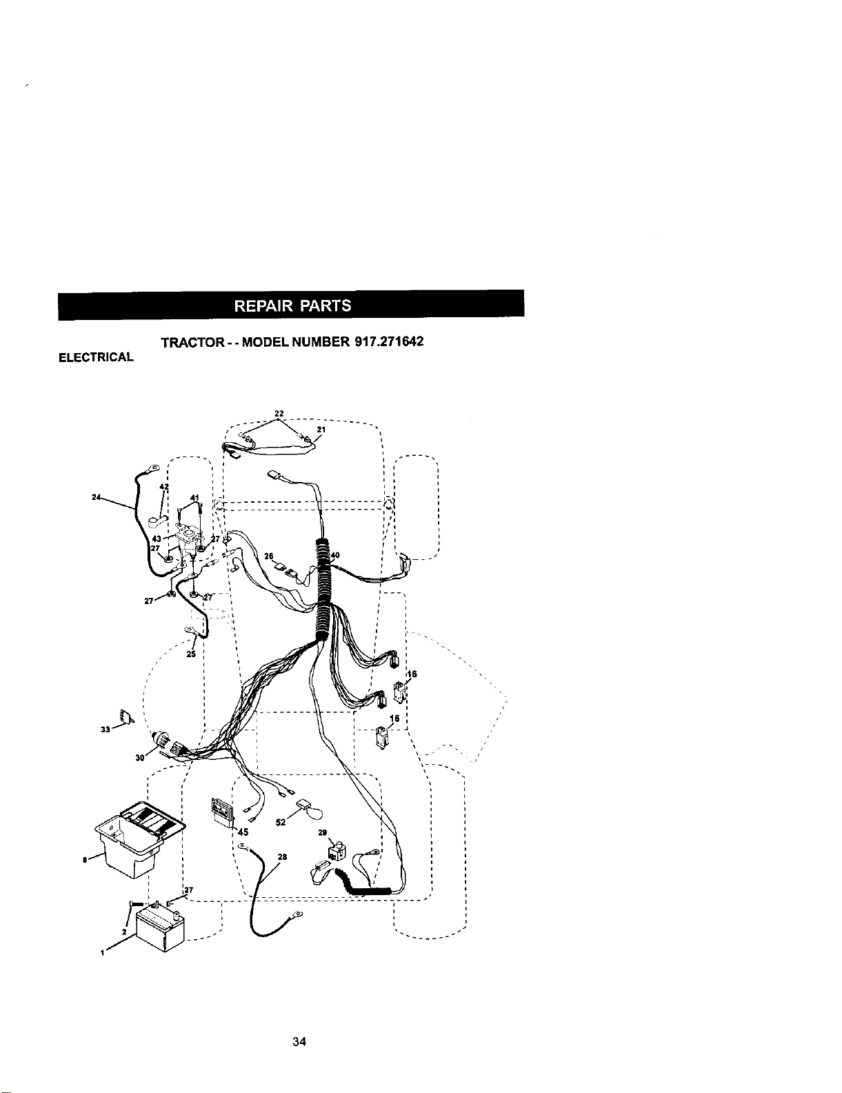
ELECTRICAL
TRACTOR - - MODEL NUMBER 917.271642
2S
J
34
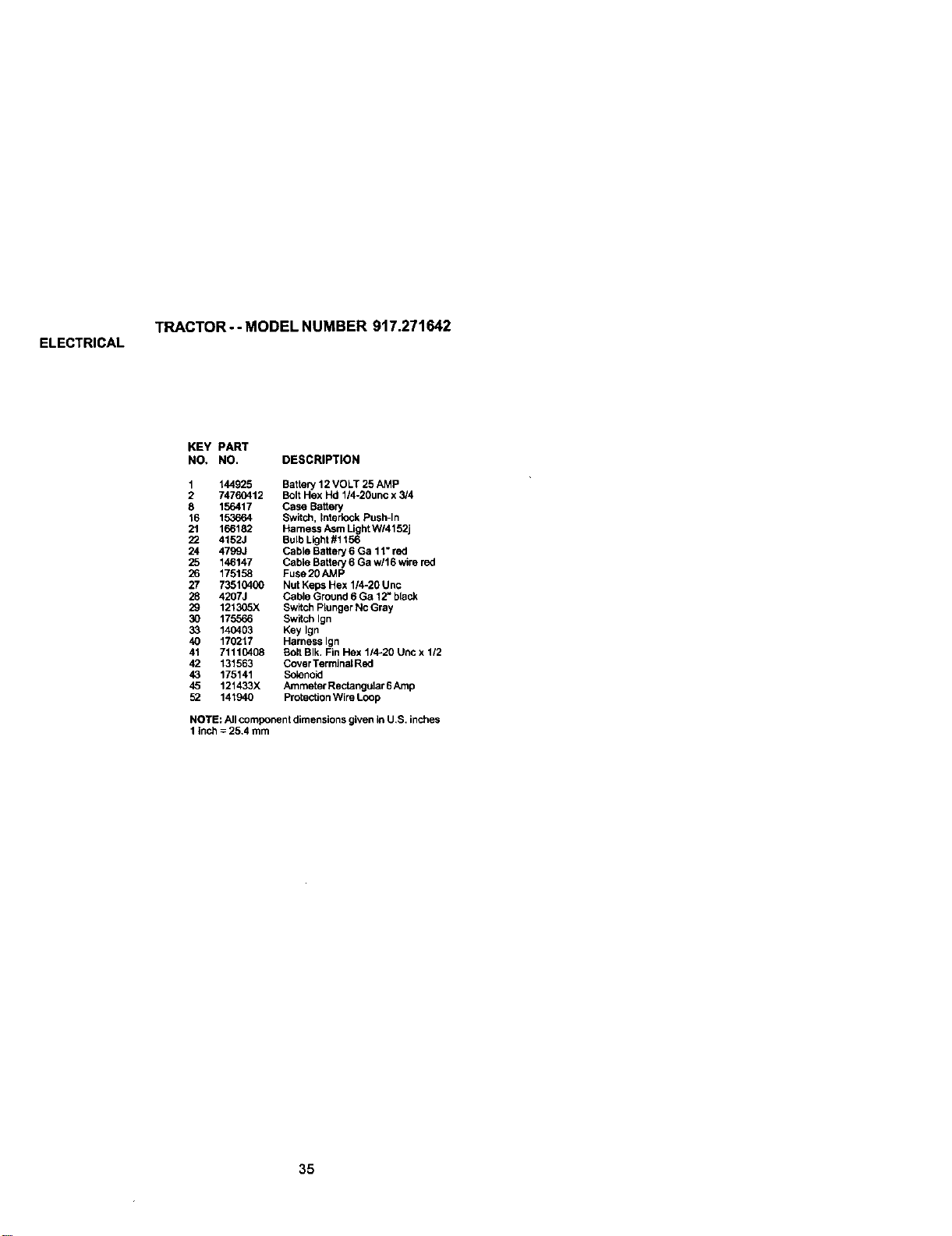
ELECTRICAL
TRACTOR-- MODEL NUMBER 917.271642
KEY PART
NO, NO. DESCRIPTION
1 144925 Battery 12 VOLT 25 AMP
2 74760412 Bolt Hex Hd 1/4-20unc x 3/4
8 156417 Case Battery
16 153664 Switch, Interlock Push-In
21 166182 Harness Asm Light W/4152j
22 4152J Bulb Light#1156
24 4799,} Cable Battery 6 Ga 11" red
25 146147 Cable Batte_ 6 Ga w/l 6 wire red
26 175158 Fuse20AMP
27 73510400 Nut Keps Hex 1/4-20 Unc
28 4207J Cable Ground 6 Ga 12" black
29 1213(_X Switch Plunger Nc Gray
30 175566 Switch Ign
33 140403 Key Ign
40 170217 Harness Ign
41 71110408 Bolt BIk. Fin Hex 114-20 Uric x 112
42 131563 Cover TerminalRed
43 175141 Sctenoid
45 121433X Ammeter Rectangular 6 Amp
52 141940 Protection Wire Loop
NOTE: All component dimensions given in U,S. inches
1 inch = 25.4 mm
35

TRACTOR - - MODEL NUMBER 917.271642
CHASSISAND ENCLOSURES
53
55 57
208 9
208
54
64
44 _ _° 1
2011
36
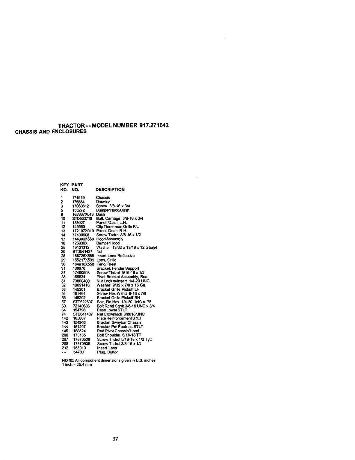
TRACTOR - - MODEL NUMBER 917.271642
CHASSISAND ENCLOSURES
KEY PART
NO. NO. DESCRIPTION
1
2
3
5
9
10
11
12
13
14
17
18
25
26
28
29
3O
31
37
38
51
52
53
54
55
57
6O
64
74
142
143
144
145
2O6
207
2O8
212
174619 Chassis
176554 Drav,Oa_
17060612 Screw 3/8-16 x 314
155272 Bumper Hood/Dash
168337X013 Cash
STD533710 Bolt, Carriage 3/8-16 x 3/4
155927 Panel, Dasi_, LH.
145660 Clip Tinnemla nGrille P/L
172107X010 Panel, Dash, R.H.
17490608 Screw Thdrut 3/8-16 x 1/2
144983.X558 Hood Assembly
126938X Burnper Hood
19131312 Washer 13/32 x 13/16 x 12 Gauge
_1437 Nut
156725X558 Insert Lens Reflective
155217X599 Lens, Grille
164918X558 Fend/Ftrest
139976 Bracket, Fender Support
17490508 Borew Thdrol 5/16-18 x 1/2
169834 Pivot Bracket Assembly, Rear
73800400 Nut Lock w/Insert 114-20 UNC
19091416 Washer 9132x718x16Ga.
145201 Bracket Grille Pickoff LH
161464 Screw Hex Wshd 8-18 x 718
145202 Bracket Grille Pickoff RH
STD5223O7 Bolt, Fin Hex 1/4-20 UNC x .75
72140606 Bolt Rdhd Sqnk 3/8-16 UNC x 3/4
154798 Dash Lower STLT
$3"[T541437 NutCrownlock 3/8016UNC
165867 Plate Reinforcement STLT
154966 Bracket Swaybar Chassis
154207 Bracket Pnt Footrest STLT
156524 Rod Pivot Chassis/Hood
170165 BOlt Shoulder 5/16-18 TT
17670508 Screw Thdml 5/16-18 x 1/2 Tytt
17670608 Screw Thdrol 3/8-16 x 1/2
165919 Insert Lens
5479J Piog, Button
NOTE: All component dimensions given LnU.S. inches
1 inch = 25.4 mm
37
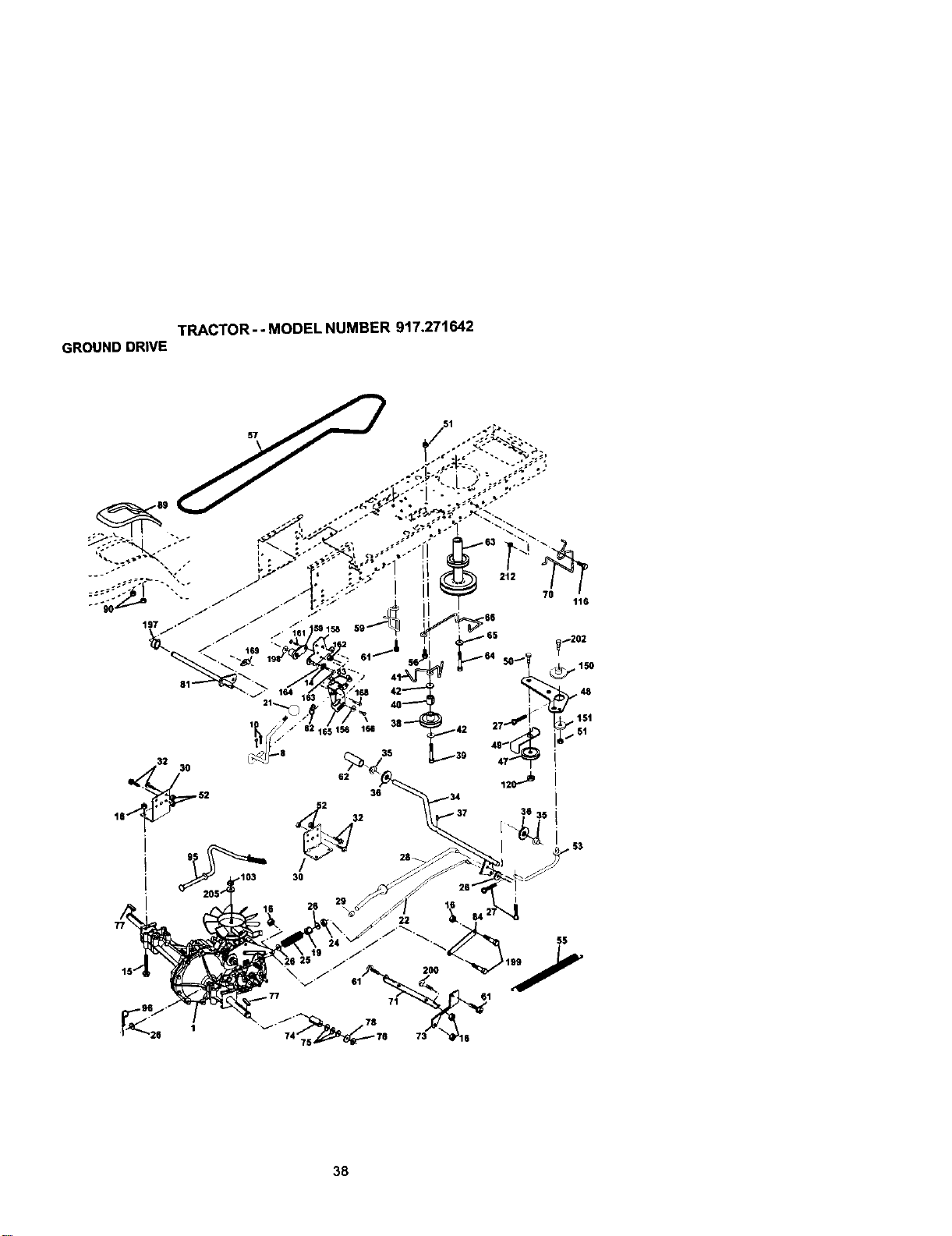
TRACTOR - - MODEL NUMBER 917.271642
GROUND DRIVE
38
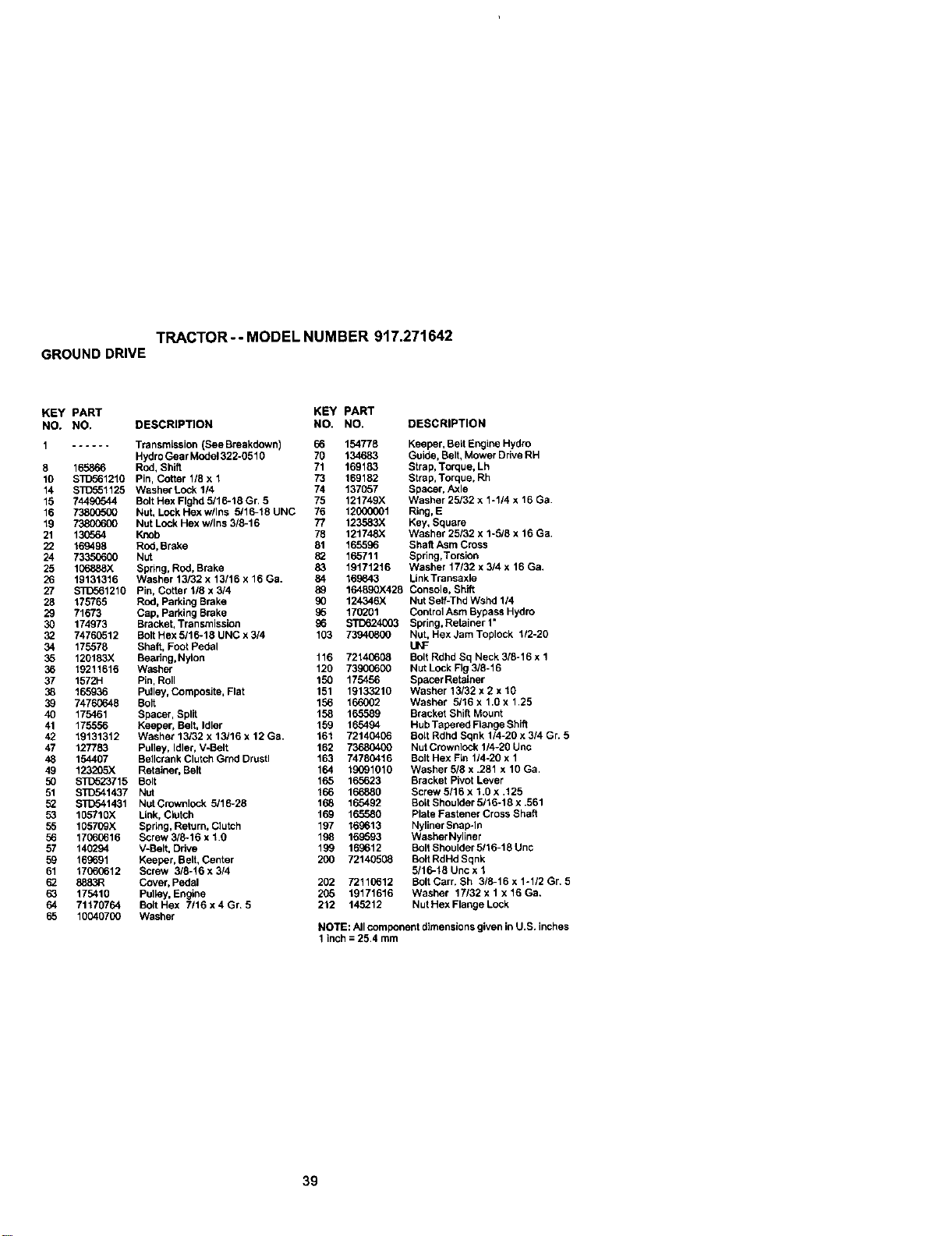
TRACTOR - - MODEL NUMBER 917.271642
GROUNDDRIVE
KEY PART KEY PART
NO. NO. DESCRIPTION NO. NO. DESCRIPTION
1 ...... TransmLssion (See Breakdown) 66 154778
HydroGear Mede1322-0510 70 134683
8 165866 Rod, Shift 71 169183
10 S]1To61210 Pin, Cotter 1/8 x 1 73 169182
14 STD551125 Washer Lock 114 74 137057
15 7449(_44 Bolt Hex Flghd 5/16-18 Gr. 5 75 121749X
16 73800500 Nut, Lock Hexw/Ins 5/16-18 UNC 76 12000001
19 7380(To00 Nut Lcck Hex w/Ins 3/8-16 77 123583X
21 130564 Knob 78 121748X
22 169498 Red, Brake 81 165596
24 73350600 Nut 82 165711
25 106888X Spring, Rod, Brake 83 19171216
26 19131316 Washer 13/82 x 13/16 x 16 Ga. 84 169843
27 STD561210 Pin, Cottar 1/8 x 3/4 89 164890X426
28 175765 Red, Parking Brake 90 124346X
29 71673 Cap, Parking Brake 85 170201
30 174973 Bracket, Transmission 96 STD624003
32 74760512 Bolt Hex 5/16-19 UNC x 3/4 103 73940800
34 175578 Shaft, Foot Pedal
35 120183)( Bearing,Nylon 116 72140608
36 19211616 Washer 120 73900600
37 1572H Pin, Roll 150 175456
38 165936 Pulley, Composite, Flat 151 19133210
39 74760646 Bolt 156 166002
40 175461 Spacer, Split 158 165589
41 175556 Keeper, Belt, Idler 159 165494
42 19131312 Washer 13/32 x 13/16 x 12 Ga. 161 72140406
47 127783 Pulley, Idler, V-Belt 162 73680400
48 154407 Be]lcrank Clutch Grnd Drustl 163 74780416
49 123205X Retainer, Belt 164 19091010
50 ST1_23715 Bolt 165 165623
51 STIT841437 Nut 166 166880
52 STD541431 NutCmwnlock 5/16-28 168 165492
53 105710X Link, Clutch 169 165580
55 105709X Spring, Return, Club:h 197 169613
56 1706(;616 Screw 3/8-16 x 1.0 198 169593
57 140294 V-Belt. Drive 199 169612
59 169691 Keeper, Belt, Center 200 72140508
61 17060612 Screw 3/8-16 x 3/4
62 8883R Cover, Pedal 202 72110612
63 175410 Pulley, Engine 295 19171616
64 71170764 Bolt Hex 7116 x 4 Gr. 5 212 145212
65 10040700 Washer
Keeper, Be6 Engine Hydro
Guide, Belt, Mower Drive RH
Strap, Torque, Lh
Strap, Torque. Rh
Spacer. Axle
Washer 25/32 x 1-1/4 x 16 Ga.
Ring, E
Key, Square
Washer 25132 x 1-5/8 x 16 Ga.
Shaft Asm Cross
Spring,Torsion
Washer 17/32 x 3/4 x 16 Ga.
Link Transaxle
Console, Shift
Nut Sef-Thd Wshd 114
Control Asm Bypass Hydro
Spring, Retainer 1•
Nut, Hex Jam Toplock 1/2-20
UNF
Bolt Rdhd Sq Neck 3/6-16 x 1
Nut Lock Fig 3/8-16
Spacer Retainer
Washer 13/32 x 2 x 19
Washer 5/16 x 1,0 x 1.25
Bracket Shift Mount
Hub Tapered Flange Shift
Bolt Rdhd Sqnk 1/4-20 x 3/4 Gr. 5
Nut Crownlock 114-20 Unc
Bolt Hex Fin 1/4-26 x 1
Washer 5/8 x .281 x 10 Ga.
Bracket Pivot Lever
Screw 5/16 x 1.0 x .125
Bolt Shoulder 5/16-18 x .561
Plate Fastener Cross Shaft
Nyliner Snal_ln
Washer Nyliner
Bolt Shoulder 5/16-18 Unc
Bo6 RdHd Sqnk
5/16-18 Unc x 1
Bolt Carr. Sh 3/8-16 x 1-1/2 Gr. 5
Washer 17/32 x 1 x 16 Ga.
Nut Hex Flange Lock
NOTE: All component dimensions given in U.S. inches
1 inch = 25.4 mm
39
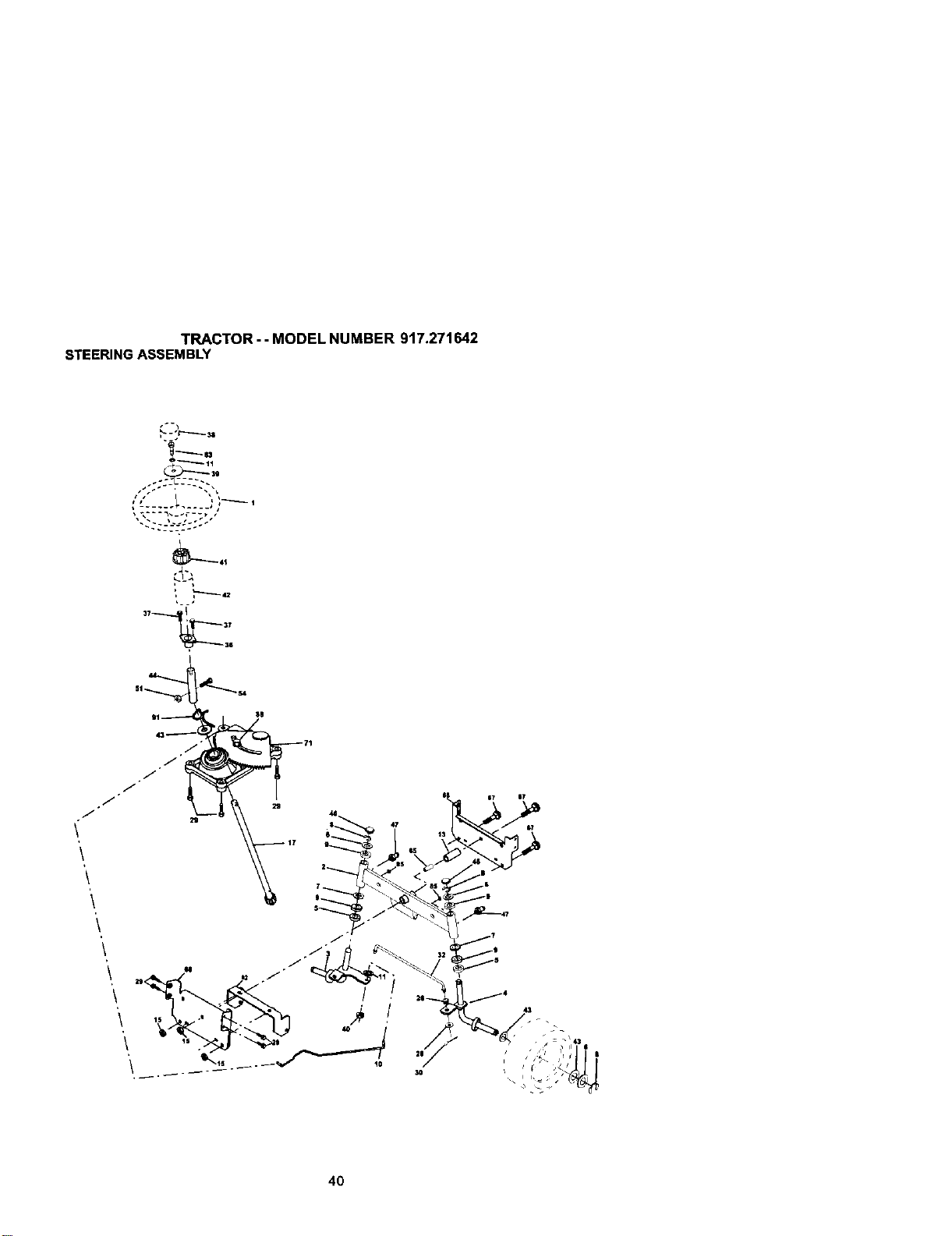
TRACTOR- - MODEL NUMBER 917.271642
STEERINGASSEMBLY
/
/
.. :---_-:°.-
l_ _ 36
40
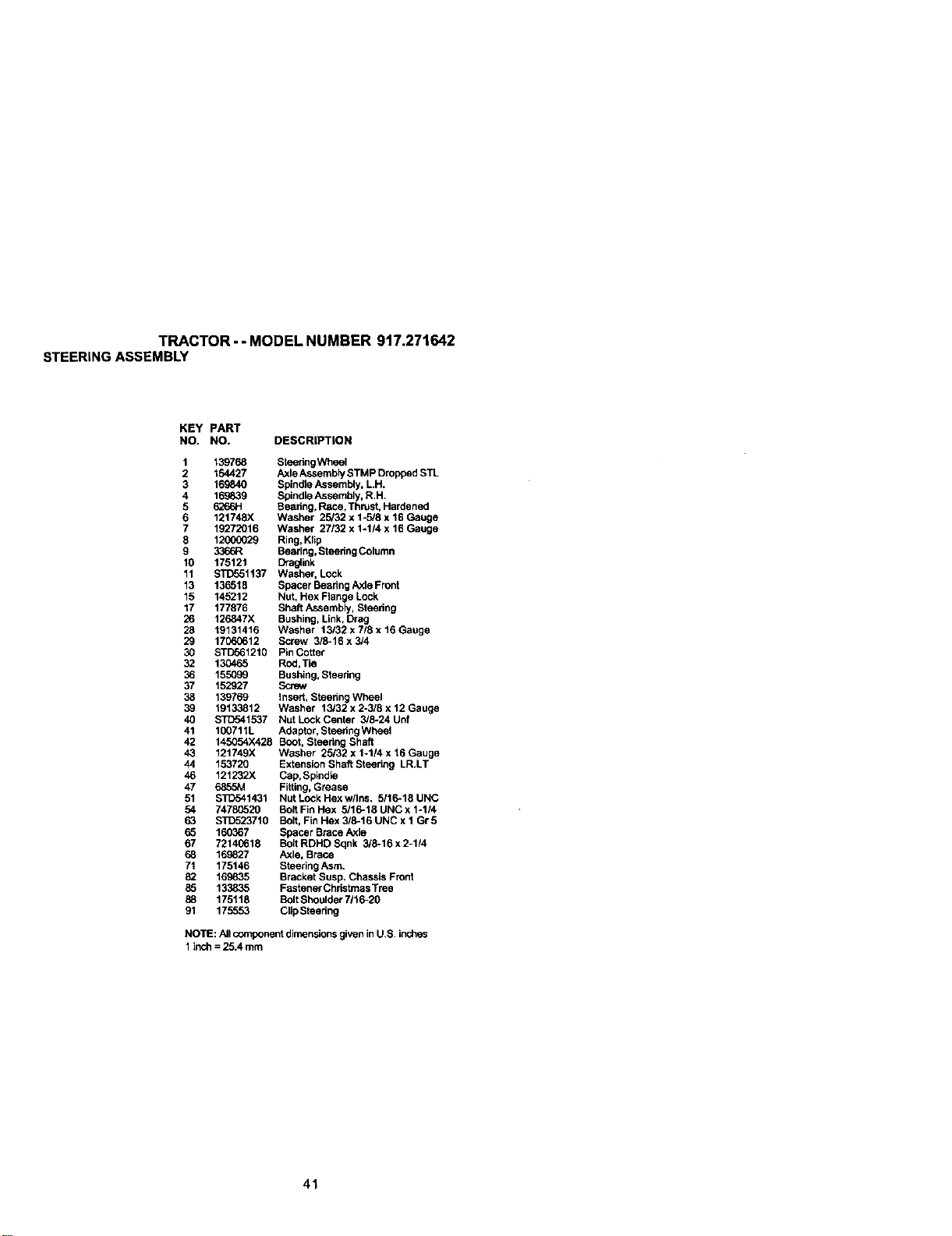
TRACTOR - - MODEL NUMBER 917.271642
STEERINGASSEMBLY
KEY PART
NO. NO. DESCRIPTION
1 139768 Steedng Wheel
2 154427 Axle Assembly STMP Dropped STL
3 169840 Spindle Assembly, LH.
4 189839 Spindle Assembly, R,H.
5 6266H Bearing, Race, Thrust, Hardened
6 121748X Washer 25/32 x 1-5/8 x 16 Gauge
7 19272016 Washer 27132 x 1-1/4 x 16 Gauge
8 12000029 Ring, Klip
9 3366R Bearing. Steedng Column
18 175121 D_a_ink
11 STD551137 Washer, Lock
13 136518 Spacer Beadng Axio Front
15 145212 Nut, Hex Flange Lock
17 177876 Shaft Assembly, Steedng
26 126847X Bushing, Link, Drag
28 19131415 Washer 13/32 x 7/8 x t6 Gauge
29 17060612 Screw 3/6-16 x 3/4
30 STD561210 Pin Cotter
32 130465 Red,Tie
36 155099 Bushing. Steedng
37 152927 Screw
38 139769 Insert, Steedng Wheel
39 19133812 Washer 13/32 x 2-3/8 x 12 Gauge
40 STD541537 Nut Lock Center 3/6-24 Unf
41 100711L Adaptor, Steedng Wheel
42 145054X426 Boot, Steedng Shaft
43 121749X Washer 25/32 x 1-1/4 x 16 Gauge
44 153720 Extension Shaft Steedng LRiT
46 121232X Cap,Spindk_
47 6855M Fitting, Grease
51 S]_541431 NutLockHexwllns. 5/16-18UNC
54 74780520 Bolt Fin Hex 5/16-18 UNC x 1-114
63 $I_523710 Bolt. Fin Hex 3/6-16 UNC x 1 Gr 5
65 160367 Spacer Brace Axle
67 72140618 Bolt RDHD Sqnk 316-16x2-114
68 169827 Axle. Brace
71 175146 Steering Asm.
82 169835 Bracket Susp. Chassis Front
85 133835 Fastener ChdstmasTree
88 175118 Bolt Shoulder 7116-20
91 175553 Clip Steedng
NO'I1E:All component dimensionsgiven inU.S. inches
1inch = 25.4 mm
41
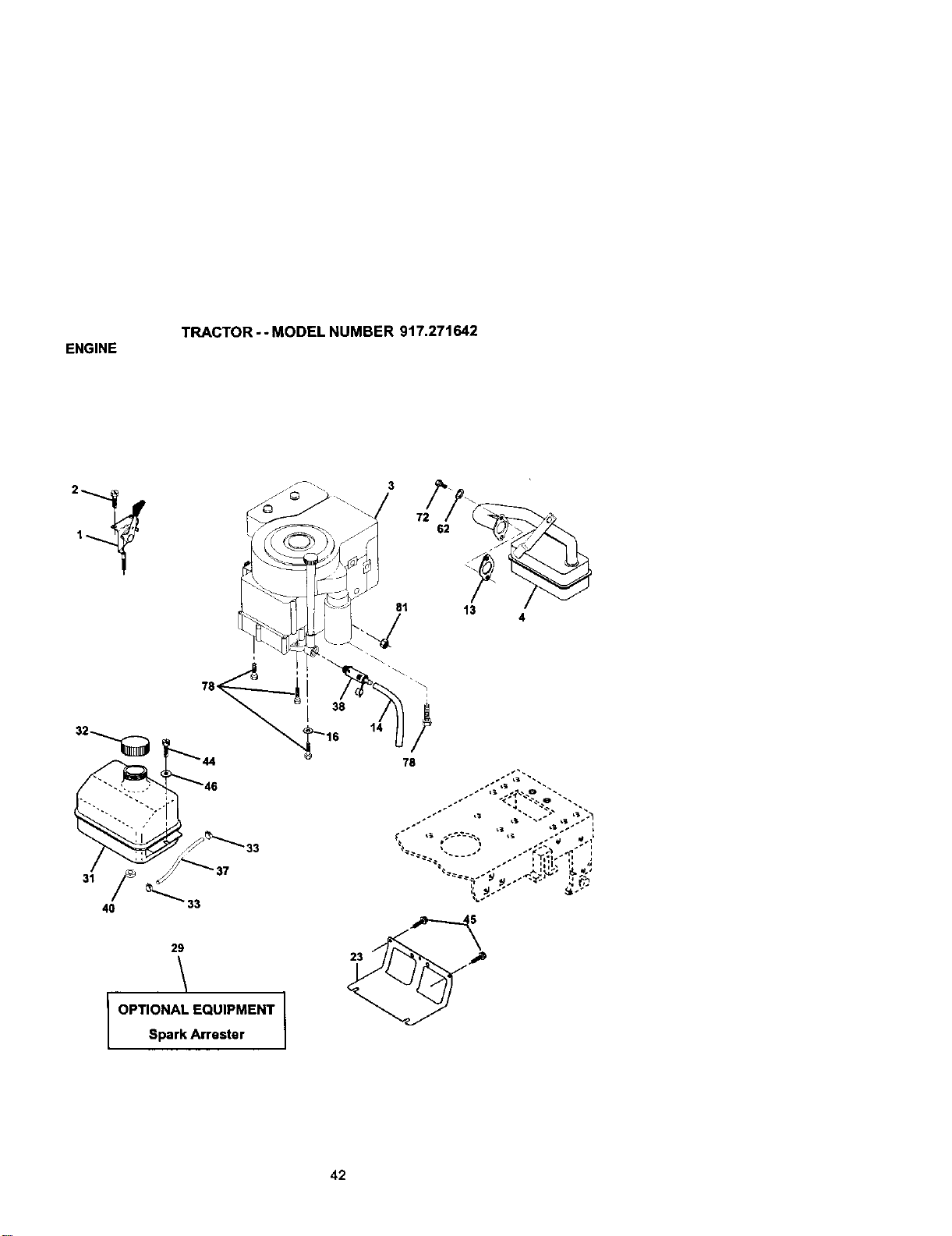
ENGINE
TRACTOR - - MODEL NUMBER 917.271642
29
I OPTIONAL EQUIPMENT
Spark Arrester
72
62
81 13
78
42
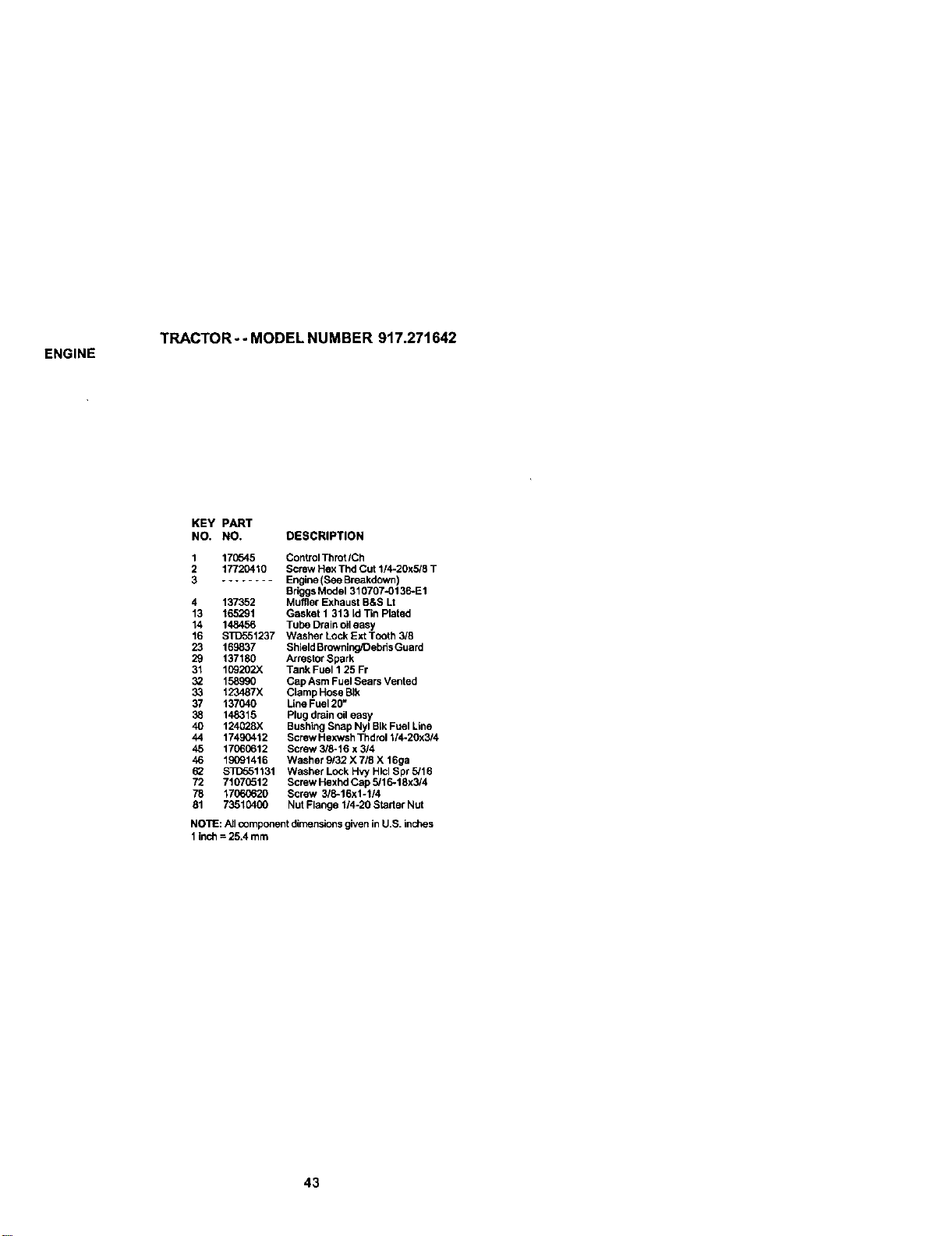
ENGINE
TRACTOR - - MODEL NUMBER 917.271642
KEY PART
NO. NO. DESCRIPTION
1 17_545 ControlThrot/Ch
2 17720410 Screw Hex Thd Cut 1/4.20x5/8 T
3 ........ Engine (See Breakdown)
BriggsModel 310707-0136-E1
4 137352 Muffler Exhaust B&S Lt
13 165291 Gasket 1 313 Id Tin Platad
14 148456 Tube Drain oileasy
16 STD551237 Washer Lock Ext Tooth 3/8
23 169837 Shield Browning/Debris Guard
29 137180 Arrestor Spark
31 109202X Tank Fuel 1 25 Fr
32 158G90 Cap Asm Fuel Sears Vented
33 123487X Clamp Hose BIk
37 137040 Line Fuel 20_
38 148315 Plug drain oileasy
40 124028X Bushing Snap Nyl BIkFuel Line
44 17490412 Screw Hexwsh Thdrol 1/4.20x3/4
45 17060612 Screw 3/8-16 x 3/4
46 19091416 Washer 9132X 7/8 X 16ga
62 S]1_51131 Washer Lock Hvy Hlcl Spr _16
72 71070512 Screw Hexhd Cap 5/16-18x3/4
78 17(60620 Screw 3/8-16x1-1/4
81 73510400 Nut Flange 1/4-20 Starter Nut
NOTE: AJlcomponent dimensions given in U.S. inches
1 inch = 25.4 mm
43
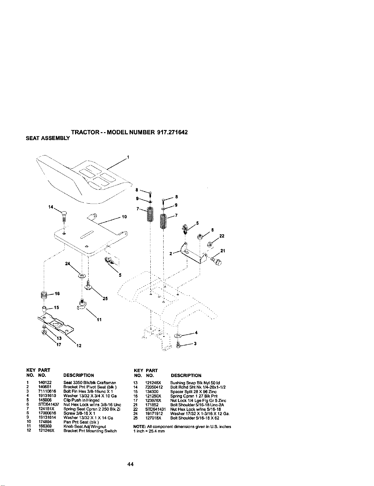
SEATASSEMBLYTRACTOR--MODELNUMBER917.27t642
\
KEY PART
NO. NO. DESCRIPTION
1 140122 Seat 3350 SIk/bik Craftsman
2 14(_51 Bracket Pnt Pivot Seat (blk)
3 7111[;616 Bolt Fin Hex 3/8-16unc X 1
4 19131610 Washer 13432 X 3/4 X 10 Ga
5 14_,006 Clip Push In Hinged
6 _1437 Nut Hex Lock w/Ins 3/8-16 Unc
7 124181X Spring _eat Cprsn 2 250 B}kZi
8 17000616 So'ew 3/8-16 X 1
9 19131614 Washer13/32XlX14Ga
10 174894
Pan Pnt Seat (blk)
11 166369 Knob Seat Ad Wingnu
12 121246)( Bracke PntMounttngSwRch
KEY PART
NO. NO. DESCRIPTION
13 121248X Bushing Snap BIk Ny150 Id
14 72_._0412 Suit Rdhd Sht Nk 1/4-20x1-1/2
15 134300
Spacer Split 28 X 96 Z nc
16 121250X Spring Cprsn 1 27 BJkPn
17 123976X Nut L_Ck 1/4 Lge Fig Gr 5 Zinc
21 171852 Suit Shoulder 5/16-18 Unc_2A
22 STD541431 Nut Hex LOckwllns 5/16-18
24 19171912 WasherlTI32Xl_/16xIzGa.
25 127018x Suit Shoulder 5/16-18 X 6;2
NOTE: All component dimensint_sg_ve,_in U.S. inches
1 inch = 25.4 rnm
44
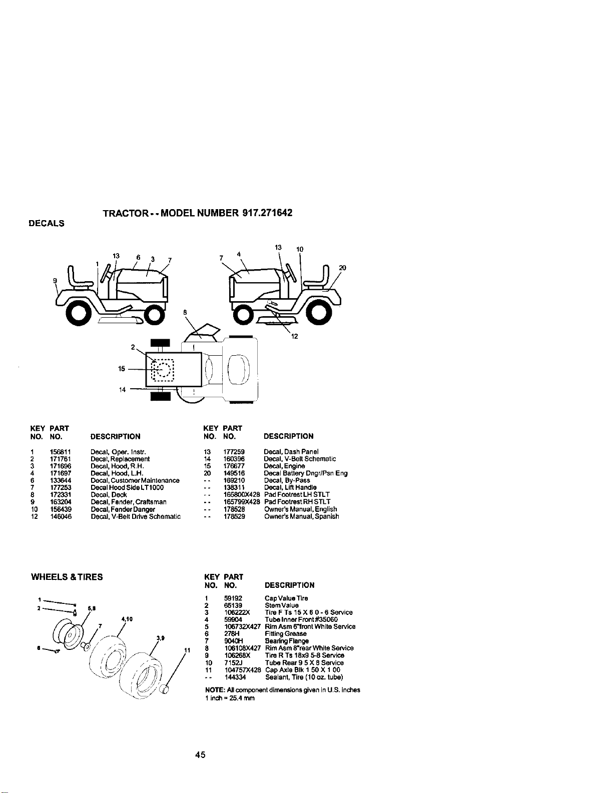
DECALS
TRACTOR - - MODEL NUMBER 917.271642
13
9 1 13 6 3 7 7_
8 _
2 n r,
10
12
KEY pART
NO. NO.
1 156811
2 171761
3 171696
4 171697
6 133644
7 177253
8 172331
9 163204
10 156439
12 146046
KEY PART
DESCRIPTION NO. NO, DESCRIPTION
Decal Oper. InsV. 13 177259 Decal, Dash Panel
Decat, Replacement 14 160396 Decal, V-Belt Schematic
Decal, Ho_xI, R.H, 15 176677 Decal, Engine
Decal, Hood, LH. 20 149616 Decal Battery Dngr/Psn Eng
Decal, Customer Maintenance - - 169210 Decal, By-Pass
Decal Hood Side LT1000 -- 138311 Decal, Lift Handle
Decal, Deck - - 165800)(428 Pad Footrest LH STLT
Decal, Fender, Craftsman -- 165799X428 Pad Footrest RH STLT
Decal, Fender Danger -- 178528 Owner's Manual, English
Decal, V-Belt Drive Schematic - - 178529 Owner's Manual, Spanish
4,10
KEY PART
NO. NO. DESCRIPTION
1 59192 Cap ValueTIre
2 65139 StemValue
3 106222X Tim F Ts 15 X 6 O- 6 Service
4 59904 Tube Inner Front #35060
5 106732X427 Rim Asm 6"_rontWhite Service
6 278H Fitting Grease
7 9040H Beadng Flange
8 106108X427 Rim Asm 8"rear White Service
9 106L:PoSX Tire R TS 18x9 5_ Service
10 7152J Tube Rear 9 5 X 8 Service
11 104757X428 Cap Axle BIk 1 50 X 1 00
- - 144334 Sealant, Tire (10 oz. tube)
NOTE: AJlcomponentdimensions given in U.S. inches
1 inch= 25.4 mm
45
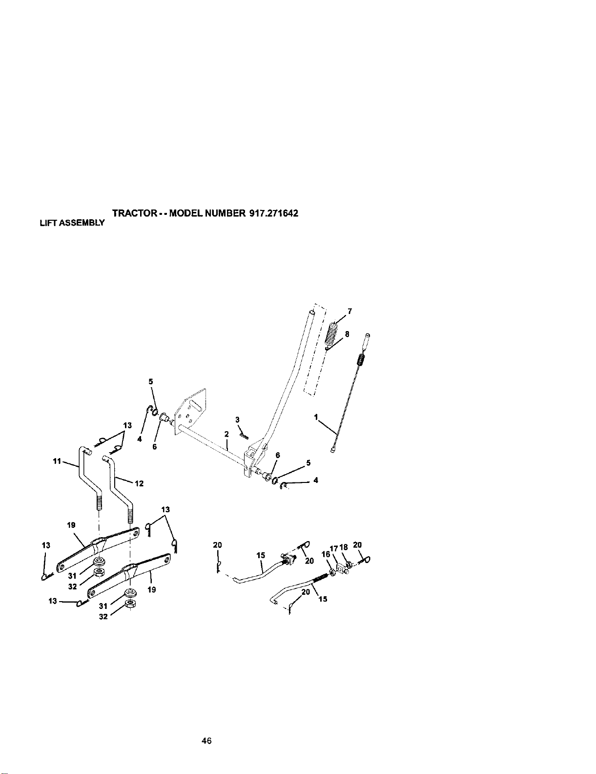
TRACTOR - - MODEL NUMBER 917.271642
LIFTASSEMBLY
5
13
32
13
19
20
3
15
6
5
20
15
46

TRACTOR- - MODEL NUMBER 917.271642
LIFTASSEMBLY
KEY PART
NO, NO, DESCRIPTION
1 159460 Washer Asm Inner SpringW/Plunger
2 159471 Shaft Asm. Lift
3 105767)( Pin Groove
4 12000002 E Ring#5133-62
5 19211621 Washer 21132 x 1 x 21 Ga.
6 120183X BeadngNylong
7 125631X GdpHandleFluted
8 122365X Bufton Plunger Read
11 139865 Link Asm Lift LH.
12 139866 Link Asm LiftR.H.
13 S]_624008 Retainer Spnng
15 173288 Link Front
16 73350800 Nut Jam Hex 1/2-13 Unc
17 130171 Trunnion BIkZinc
18 73800800 Nut Lock wANsh 1/2-13 Unc
19 139868 ArmSuspension Mower
20 163552 Retainer Spdng
31 169865 Beadng, Pvt. Lift
32 7354(To00 Nut Crownlock 3/8-24
NOTE: All componentdimensJonsgiven in U.S. inches
1 inch = 25.4 mm
47
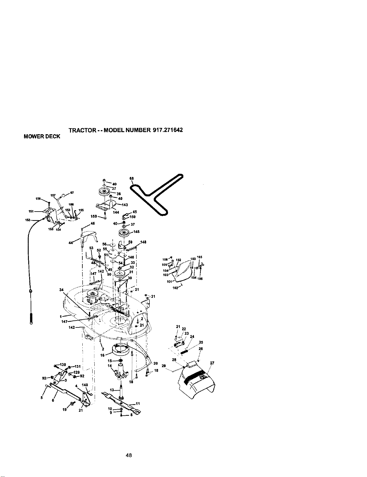
TRACTOR - - MODEL NUMBER 917.271642
MOWERDECK
68
./\_V " . i _, / "°
• 51_ 461 _ 105
' _ 331 _os , /
!a_, 50 ; 103 J f
i _ 'i_°_ ,o,_='-
142 , .. _' I _ , 21 22
l ; 15_--I_ I l _ )_ 28 " , __ - 27
30 31 i / ! 14 9_20 29
_1::_ ,, _:_l_,, _ _/
, i
5
48
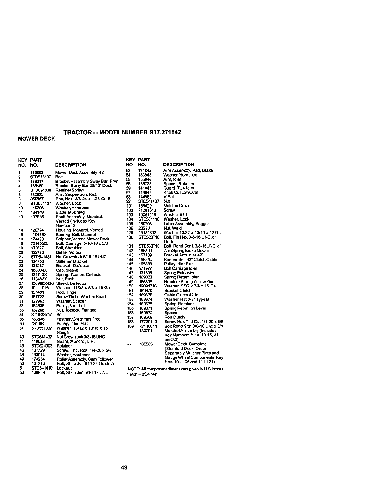
TRACTOR - - MODEL NUMBER 917.271642
MOWERDECK
KEY PART KEY PART
NO. NO. DESCRIPTION NO. NO, DESCRIPTION
1 165892 Mower Deck Assembly, 42" 53 131845 Arm Assembly, Pad, Brake
2 _107 Bolt 54 133.943 Washer, Hardened
3 138017 Bracket Assembly,Sway Bar, Front 55 155046 Arm, Idler
4 165460 Bracket Sway Bar 38/42" Deck 56 165723 Spacer, Retainer
5 $3_)624008 RetainerSpdng 59 141043 Guard, TUV Idler
6 130832 Arm, Suspension, Rear 67 149846 Knob Custom Oval
8 850857 Bolt, Hex 3/8-24 x 1.25 Gr. 8 68 144959 V-Belt
9 _1137 Washer, Lcck 92 STD541437 Nut
10 140296 Washer, Hardened 101 136420 Mulcher Cover
152 71081010 Screw
11 134149 Blade, Mulching 103 19061216 Washer #10
13 137645 ShaftAssembly, Mandrel, 104 STD551110 Washer, Lock
Vented (Includes Key 105 160793 Latch Assembly, Bagger
Number 12)
14 128774 Housing, Mandrel, Vented 106 2529J Nut, Weld
15 110485X Beadng, BaiI, Mandrel 129 19131312 Washer 13/32 x 13116 x 12 Ga.
16 174493 Stdppar, Vented MowerDeck 130 STD523710 Bolt, Fin Hex 3/8-16 UNC x 1
18 72140505 Bolt, Carriage 3/16-18 x 5/5 Gr. 5
19 132827 Bolt, Shoulder 131 STD53371g Bolt, Rdhd Sqnk5/8-16UNC x 1
20 159770 Baffle, Vortex 142 165890 ArmSpdngBrakeMower
21 STD541431 NutCrownlock5/16-18UNC 143 157109 BracketArmldler42"
22 134753 Stltfener Bracket 144 158634 Keeper Belt 42" Clutch Cable
23 131267 Bracket, Deflector 145 165888 Pulley Idler Flat
24 105304X Cap, Sleeve 146 171977 Bolt Cardage Idldr
25 123713X Spdng. Torsion, Deflector 147 131335 Spriog Extension
26 110452X Nut. Push 148 169022 Spdng Return idler
27 130968X428 Shtald, Deflector 149 165898 Retainer Spdng Yellow Zinc
28 19111016 Washer 11152xs/Sx16Ga, 150 19091216 Washer g/32x3/4x 16Ga.
29 131491 Red,Hinge 151 169670 Bracket Clutch
30 157722 Screw ThdtolWasher Heed 152 169676 Cable Clutch 42 In
31 12S963 Washer, Spacer 153 169674 Washer Flat 3/8" Type B
32 153535 Pulldy, Mandrel 154 169675 Spdng Retainer
33 137266 Nut, Toplock, Flanged 155 169671 Spring Retenlton Lever
34 STD533717 Bolt 156 169672 Spacer
35 133835 Fastner, ChrLstmasTree 157 169669 Rod Clutch
158 17720410 Screw Hex Thd Cut 1/4.20 x 5/8
36 131494 Pulley, Idler, Flat
37 STD551037 Washer 13/32 x13/16 x16 159 72140614 BoltRdhdSqns/6-16Uncx5/4
Gauge - - 130794 Mandrel Assembly (Includes
40 S'1D341437 NutCrownlock 5/6-16 UNC Key Numbers 8-10, 13-15, 31
44 140088 Guard, Mandrel, L,H, and 32)
45 STD624003 Retainer -- 169583 Mower Deck, Complete
46 137729 Screw, Thd. Roll 1/4-20 x 5/8 (Standard Deck, Order
48 133944 Washer, Hardened Separately Mulcher Plate and
49 174284 RoltarAssembly, Cam Follower Gauge Wheel Components, Key
50 131340 Bolt, Shoulder #16-24 Grade 5 Nos. 101-106 and 111-121)
51 SIT)541410 Locknut NOTE: All component dimensions given in U.S.inches
52 139888 Bolt,Shoulder 5/16-18 UNC 1inch = 25.4 mm
49
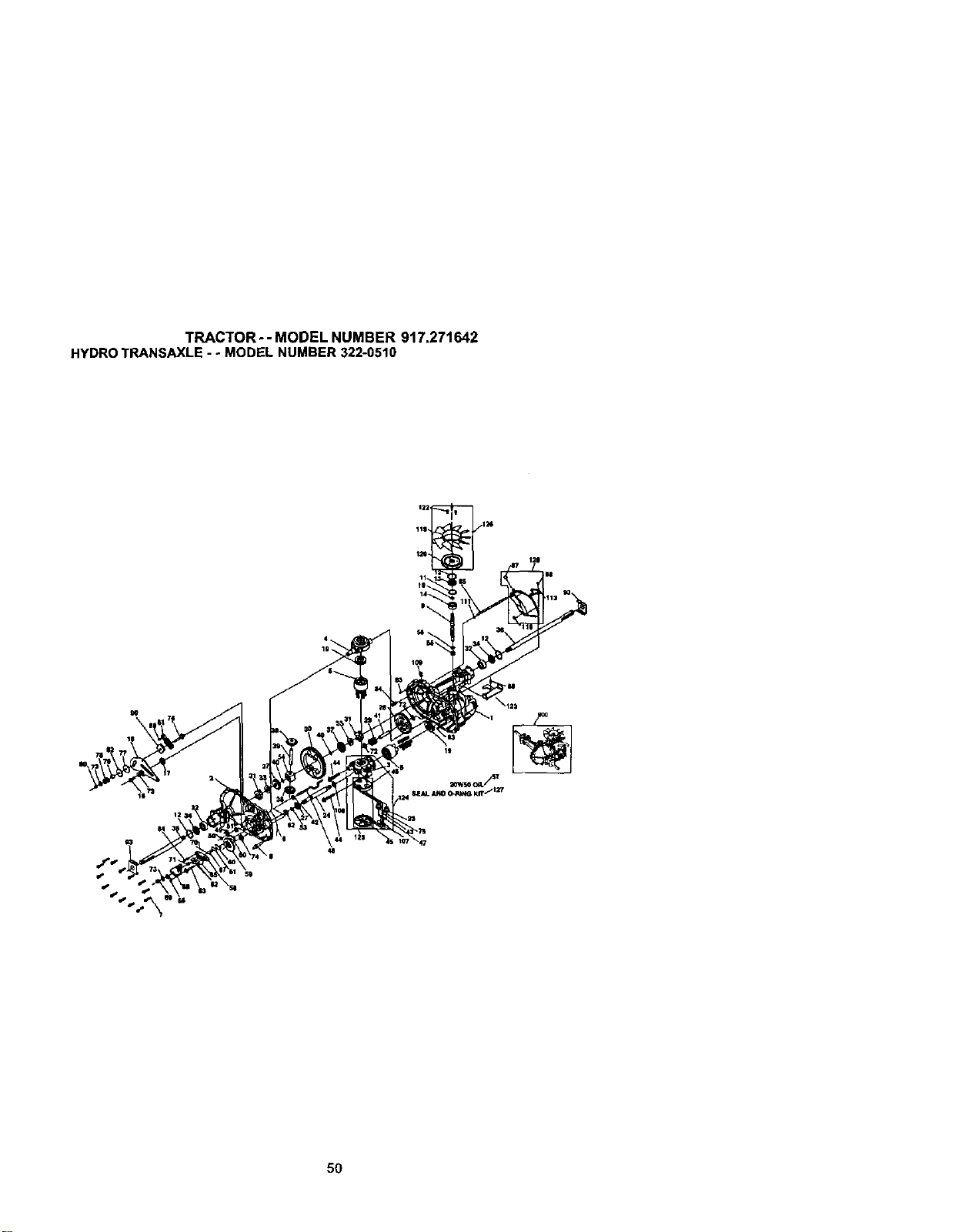
TRACTOR - - MODEL NUMBER 917.271642
HYDROTRANSAXLE- - MODELNUMBER322-0510
\
50
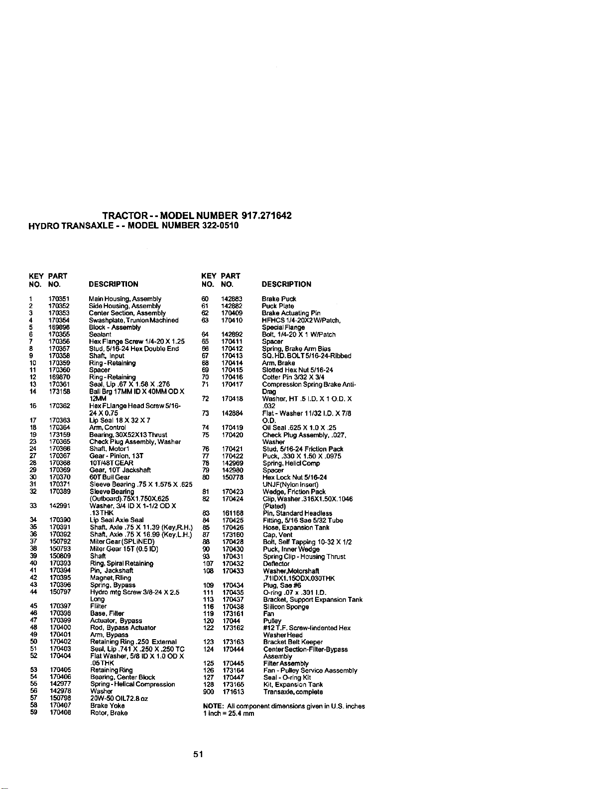
TRACTOR- - MODEL NUMBER 917.271642
HYDROTRANSAXLE- - MODELNUMBER322-0510
KEY PART KEY PART
NO. NO. DESCRIPTION NO. NO. DESCRIPTION
1 170351 Maio Housing, Assembly 60 142883 Brake Puck
2 170352 Side Housing, Assembly 61 142882 Puck Plate
3 170353 Center Section, Assembly 62 170409 Brake Actuating Pin
4 170354 Swashplata,Trunion Machined 63 170410 HFHCSll4-2OX2WIPatch,
5 169898 Block - Assembly Spacial Flange
6 170355 Sealant 64 142892 Bolt, 114-26 X 1 W/Patch
7 170356 Hex Flange Screw 114-20 X 1.25 65 170411 Spacer
8 170357 Stud, 5/16-24 Hex Double End 66 170412 Spring, Brake Arm Bias
9 170358 Shaft, Input 67 170413 SQ. HD. BOLT 5/16-24-Ribbed
10 170359 Ring-Retaining 68 170414 Arm, Brake
11 170360 Spacer 69 170415 Sloged Hex Nut 5/16o24
12 169870 Ring - Retaining 70 170416 Cotter Pin 3/32 X 3/4
13 170361 Seal, Lip .67 X 1.58 X .276 71 170417 Compression Spring BrokeAnti-
14 173158 BallBrg 17MM ID X 40MM OD X Drag
1_%.1M 72 170418 Washer, HT .5 I.D. X 10.D. X
16 170362 HexFLlange Head Serew 5/16- .032
24 X 0.75 73 142884 Flat - Washer 11132 I.D. X 7/8
17 170363 LipSeal 18 X 32 X 7 O.D.
18 170364 Arm, Control 74 170419 Oil Seal .625 X 1.0 X .25
19 173159 Beadng, 30X52X13 Thrust 75 170420 Check Plug Assembly, .027,
23 170365 Chec_ Piog Assembly, Washer Washer
24 170366 Shaft, Motor 1 76 170421 Stud, 5/16-24 Friction Pack
27 170367 Gear - Pinion, 13T 77 170422 Puck, .330 X 1.50 X .0975
28 170368 10TI48T GEAR 78 142969 Spdng, HeliclComp
29 170369 Gear, lOT Jackshaft 79 142980 Spacer
30 170370 60T BUllGear 80 150778 Hex Lock Nut 5/16-24
31 170371 Sleeve Beadng .75 X 1.575 X .625 UNJF(Nyion insert)
32 170389 8laeve Beadng 81 170423 Wedge, Fdction Pack
(Outboard).75X 1.750X.625 82 170424 Cfip, Washer .316X1.50X.1046
33 142991 Washer, 3/4 ID X 1-1/2 OD X (Plated)
.13THK 83 161168 Pin, Staedard Headless
34 170390 Lip Seal Axle Seal 84 170425 Fitting,5/16 Sae 5/32 Tube
35 170391 Shaft, Axle .75 X 11.39 (Key,R.H.) 85 170426 Hose, Expansion Tank
36 170392 Shaft, Asia .75 X 16.99 (Key,LH.) 87 173160 Cap. Vent
37 150792 Miter Gear (SPLINED) 88 170428 Bolt, Self Tapping 10-32 X 1/2
38 150793 Miter Gear 15T (0.5 tD) 90 170430 Puck, Inner Wedge
39 150809 Shaft 93 170431 Spdng Clip -Housing Tsiust
40 170393 Ring, Spiral Retainiog 107 170432 Deflector
41 170394 Pin, Jackshaft 108 170433 Washer,Motorshafl
42 170395 Magnet, Rliog .711DX1.15ODX.030THK
43 170396 Spr!ng, Bypass 109 170434 Plug, Sae #6
44 150797 Hydro rntg Screw 3/8-24 X 2.5 111 170435 O-riog .07 x .301 LD.
Long 113 170437 Bracket, Support Expansion Tank
45 170397 Flilter 116 170438 Slilicon Sponge
46 170399 Base, Filter 119 173161 Fan
47 170399 Actuator, Bypass 120 17044 Pufley
48 170400 Rod, Bypass Actuator 122 173162 #12 T.F. Screw-liodented Hex
49 170401 Arm, Bypass Washer Head
50 170402 Retaining Ring .2B0 External 123 173163 Bracket Belt Keeper
51 170403 Seal, Lip.741 X .250 X .250 TC 124 170444 CenterSection-Filter-Bypass
52 170404 Flat Washer, 5/8 ID X 1.00D X Assembly
.05THK 125 170445 Filter Assembly
53 170405 RetaioingRing 126 173164 Fan - Pulley Service Aassembly
54 170406 Beario9, Centar Block 127 170447 Seal - O-ring Kit
56 142977 Spring-Helioal Compression 128 173165 Kg, Expansion Tank
56 142978 Washer 900 171613 Transaxle, complete
57 150798 20W-50 OIL72.8 oz
58 170407 Brake Yoke NOTE: Aft component dimensions given in U.S. inches
59 170408 Rotor, Brake 1 inch = 25.4 mm
51
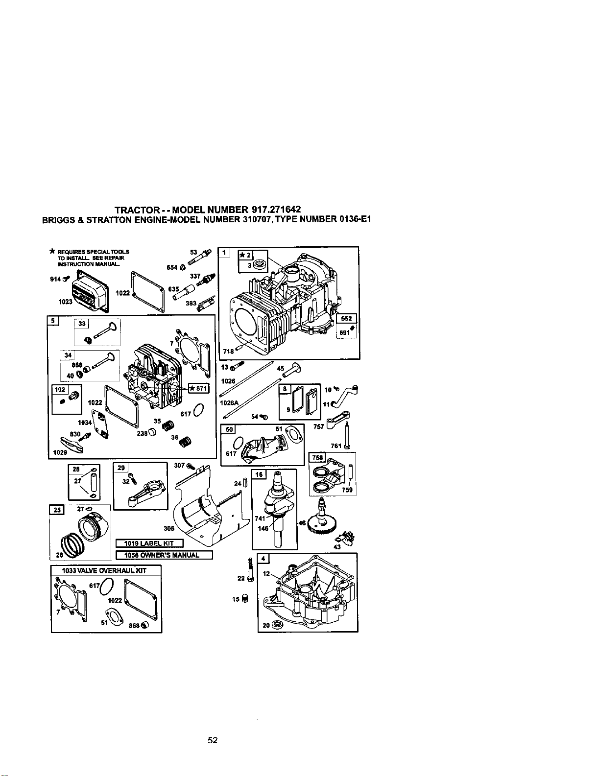
TRACTOR - - MODEL NUMBER 9t7.271642
BRIGGS& BTRATTONENGINE-MODELNUMBER310707,TYPE NUMBER0136-E1
3Ir REQUIRESSPECIALTOOLS 5_
TOINSTALL SEEREPAIR
I_STRUCTmNMANUAL 654
617
301
I 101SLA.ELKITI
I 1058 OWNER'S MANUAL
I to,,;
12
22
15_
52
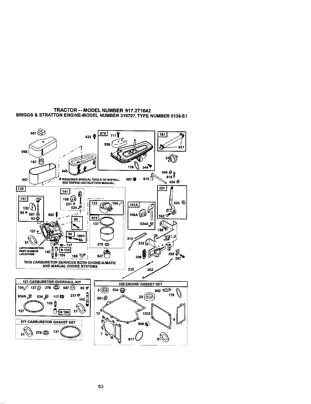
TRACTOR - - MODEL NUMBER 917.271642
BRIGGS&STRATTONENGINE-MODELNUMBER310707,TYPE NUMBER0136-E1
13o_j
95 • 987
I 127
I_w N_8_ 142
LOC4_r,_S 186 _ 947
THIS CARBURETOR SERVICES BOTH CHOKE-A-MATIC
AND MANUAL CHOKE SYSTEMS
276
176
121 CARBURETOR OVERHAUL KIT
IO4_ 12,0 2,e_ ,8,@ .5_
634A _.._ 634 _._ 1t7_ 231_142 A
137_ _ 51______
5_-_R_7U£R_R IGA7No]
141A
216 222
I 358 ENGINE GASKET SET
53
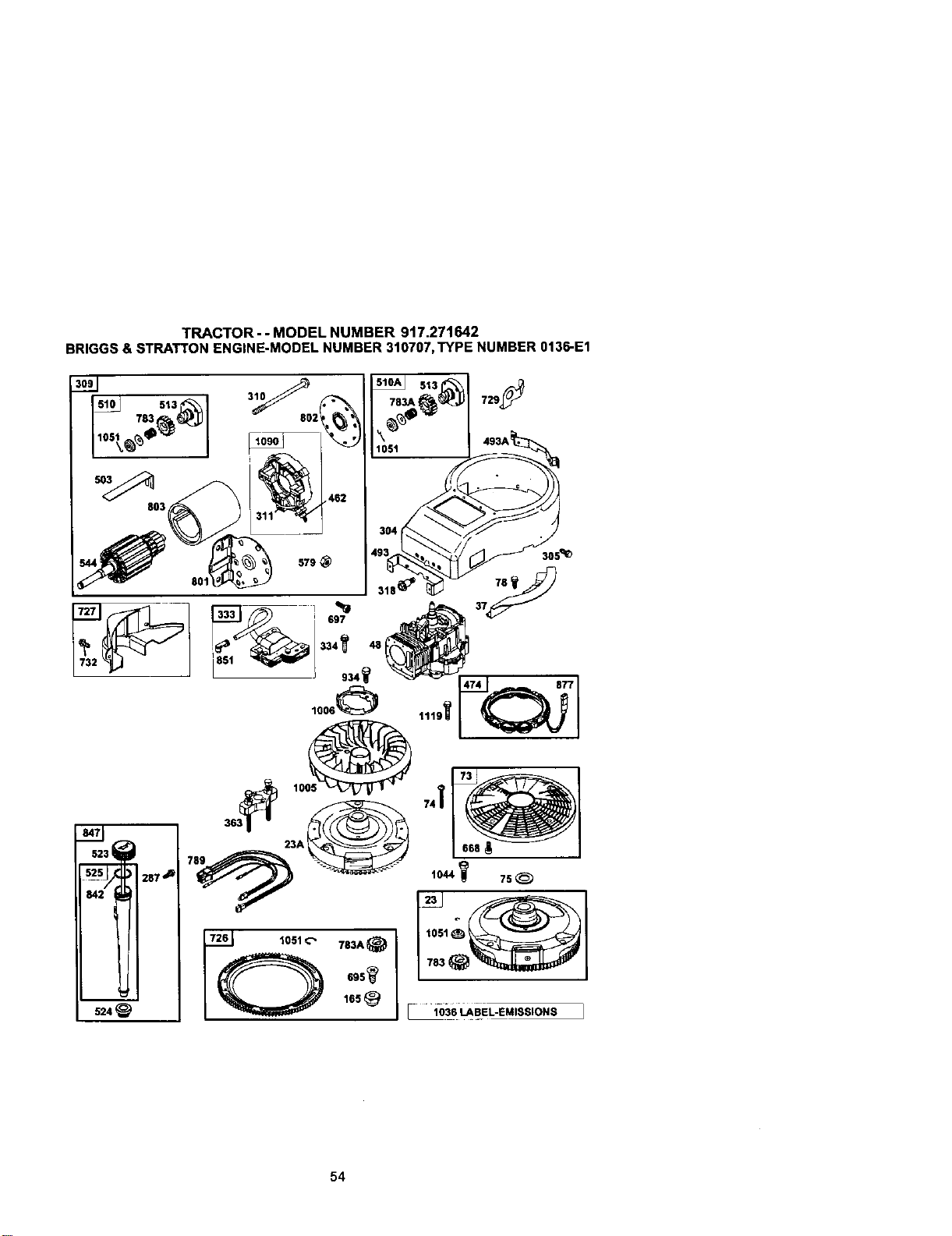
TRACTOR - - MODEL NUMBER 917.271642
BRIGGS& STRATTONENGINE-MODELNUMBER310707,TYPE NUMBER0136-E1
287 _
524
54
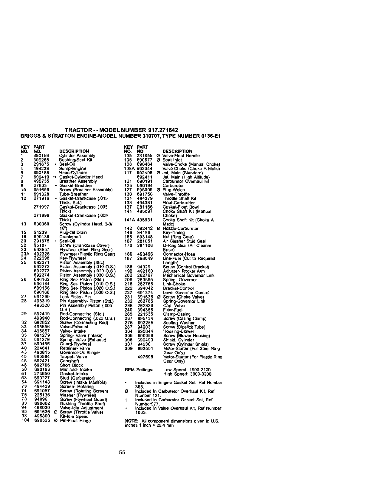
TRACTOR - - MODEL NUMBER 917.271642
BRIGGS& STRATTONENGINE-MODELNUMBER310707,TYPE NUMBER0136-E1
KEY PART KEY PART
NO. NO. DESCRIPTION NO. NO. DESCRIPTION
1 690156 CylinderAssembly 105 231855 O Valve-Float Needle
2 399265 Bushing/Seal Kit 106 690577 O Seat-Inlet
3 291675 • Seal*oil 108 690464 Valve-Choke(hanuat Choke)
4 108A 692344 Valve-Choke(Choke A Matic494238 Bump`Engine )
5 690188 Head-Cylinder 117 692406 £1 Jet, Main (Standard)
7 692410 .+ Gasket-Cylinder Head 692411 Jet, Main High Altitude)
8 495735 Breather Assembly 121 690191 Carburetor Overhau Kit
9 27803 • Gasket-Breather 125 890194 Carburetor
10 691666 Screw (Breather Assembly) 127 695005 O Plug-Welch
11 691328 Tube-Breather 130 691759 Valve-Throttle
12 271916 • Gasket-Crankcase (.015 131 494379 Throttle Shaft Kit
Thick, Std.) 133 494381 Float-Carburetor
271997 Gasket-Crankcase (.005 137 281165 Gasket-Float Bowl
Thick) 141 495097 Choke Shaft Kit (Manual
271996 Gasket-Crankcase (.009 Choke)
Thick 141A 495931 Choke Shaft Kit (Choke A
13 690360 Screw (Cyl nder Head, 3-9/ Matic)
16") 142 692412 O Nozzle-Carburetor
15 94239 Plug-OilDrain 146 94196 Key-Timing
16 690136 Crankshaft 165 693148 Nut (Ring Gear)
20 291675 . Seal-Oil 167 281051 Air Cleaner Stud Seal
22 95187 Screw (Crankcase Cover) 176 281106 O-Ring Seal (Air Cleaner
23 693557 Flywheel (Steel Ring Gear) Base)
23A 492326 Flywheel(PlasticRing Gear) 186 493496 Connector-Hose
24 222698 Key-Flywheel 187 298049 Line*Fuel (Cut t_ Required
25 692271 PistonAssembly Std.) Length)
692272 Piston Assembly (.010 O.S.) 188 94929 Screw (ControlBracket)
692273 Piston Assembly 1020 O.S./ 192 492160 Adjuster-ROCkerArm
692274 PistonAssembly .030 O.S. 202 262767 Mechanical GovernorLink
26 690162 Ring Set- PistonIStd;_ 209 260695 Bprin_- Governor
690164 Ring Set- Piston_v.Ol O.S,) 216 262766 Link-L;hoke
690166 Ring Set- Piston(.020 O.S.) 222 694042 Bracket-Control
690168 Ring Set- Piston(.630 O.S.) 227 691374 Lever-Governor Control
27 691299 Lock-PistonPin 231 891636 O Screw Choke Valve)
26 498319 Pin Assembly- Piston Std.) 232 262785 Spring-GovernorL nk
498320 P n Assemby-P ston ,005 238 262836 Cap- Valve
O.S.) 240 394358 Filter-Fuel
29 692419 Red-Connecting (Btd.) 265 221535 Clamp-Casing
499940 Red-Connecting (.020 U.S.) 267 695134 Screw (CasingClamp)
32 692852 Screw(Connecting Red) 276 692255 Sealing Washer
33 495856 Valve-Exhaust 287 94903 Screw (DipstickTube)
34 495857 Valve- intake 304 690844 Housin(i-Blower
35 691279 Spring- Valve (Intake) 305 690969 Screw _'BIowerHousing)
36 691279 Sphng- Valve (Exhaust 306 690499 Shield, Cylinder
37 690456 Guard-Flywheel 367 94930 Screw (CylinderShield)
40 224641 Retainer- Valve 309 693551 Motor-Starter(For Steel Ring
43 490815 Governor*Oil Slinger Gear Only)
45 690564 Tappet- Valve 497595 Mctor-Starter(For PlasticRing
46 692421 Camshaft Gear Only)
48 692706 Short Block
50 690193 Manifold- Intake RPM Settings: Low Speed: 1900-2100
51 273650 Gasket-Intake High Speed: 3000-3200
53 690227 Stud (Carburetor)
54 891148 Screw (Intake Manifold) Includedin Engine Gasket Bet, Ref Number
73 494439 Screen- Rotating 358.
74 691057 Screw (RotatingScreen) O Includedin CarburetorOverhaul Kit, Ref
75 225136 Washer(Flywheel) Number 121.
78 94896 Screw (F'(_lywheeluard) $ Includedin CarburetorGasket Set, Ref
93 890602 Bushing-Throttle Shaft Number977.
94 498030 Valve-Idle Adustment + Includedin Value Overhaul Kit, Ref Number
95 691636 121Screw ThrotfleVave 1033.
98 495800 Kit-Idle Speed
104 690525 O Pin-Float Hinge NOTE: All componentdimensionsgiven in U.S.
inches 1 inch= 25.4 mm
55

TRACTOR - - MODEL NUMBER 917.271642
BRIGGS&STRATTONENGINE-MODELNUMBER310707,TYPE NUMBER0136-E1
KEY PART
NO. NO.
310 690323
311 497608
318 692127
333 495859
334 94731
337 491055
344 693675
358 690189
363 19203
383 89838
404 94927
423 692129
445 496894
462 225137
467 493903
474 393474
493 690493
493A 690494
503 691532
505 691251
510 693699
510A 497606
513 398003
523 495230
524 281370
525 496113
544 497603
559 491986
562 691119
579 92278
601 95162
614 93306
616 495157
617 692138
634 690801
634A 690802
635 280872
654 94010
667 94010
668 691500
691 491323
692 690572
695 693109
697 690372
711 690703
718 230192
726 399676
727 490324
729 691224
732 94903
741 691284
757 213998
758 692423
KEY PART
DESCRIPTION NO. NO. DESCRIPTION
Screw (Starter Motor) 759 691239 Pin-Counterweight
Brush Set 761 691096 Screw Counterweight)
Screw (Mounting Bracket) 783 693713 Gear-Pnon For Steel Ring
Armature-Magneto Gear Only)
Screw (Magneto Armature) 783A 693058 Gear-Pinion (For Plastic Ring
Sparkplug Gear Only)
Screw (Casing Clamp) 789 695050 Harness- Wiring
Engine Gasket Set 801 497626 Cap-Drive
FI heel Puller 802 497607 Cap-Eod
_re r Housing-Starter
ch-Spark Plug 803 497604
Washer (Governor Crank) 830 691095 Stud (Rocker Arm)
Screw (Air Cleaner Base) 842 270920 Dipstick/Tube Seal
Filter- NC Cartdd]9 Ee 847 496415 Dipstick/Tube Assemi_y
Washer Starter Cable) 851 692424 Sparkplug Terminal
Knob-Ar Ceaner 868 499236 -+ Seal-Valve
Alternator 871 262835 Bushin_q-Guide
Bracket-Mounfng Front) 875 693686 Base-/_ir Cleaner
Bracke-Moun ng Rear) 877 393456 Wire-Alternator
Strap-Starter 914 690969 Screw (Rocker Cover)
Nut (Governor Control Lever) 934 94627 Screw (Fan Retainer)
Drive-Starter (Use With Steel 947 497672 Solenoid-Fuel
Ring Gear Only) 967 272403 Fi6er-Pre Cleaner
Drive-Starter (Use With Plastic 968 281104 Cover- Air Cleaner
Ring Gear Only) 975 495933 Bowl-Float
Clutch-Drive 977 690192 Gasket Set-Carburetor
Dipstick 987 691326 O Seal-Throttle Shaft
• Dipsfck Tube Seal 996 690678 Carburetor Shield
Dipstick Tube 1005 281400 Fan-Flywheel
Armature-Starter 1006 690452 Retainer-Fan
Bushing-Gov. Lever 1019 690180 Label Kit
Bolt (Governor Control Lever) 1022 272475 *+ Gasket-Rocker Cover
Nut (Starter Cable) 1023 691192 Cover-Rocker
Clamp-Hose 1026 494432 Rod-Push Intake
Pin-Cotter 1026A 495136 Rod-Push Exhaust
Crank-Governor 1029 224554 Arm-Rocker
*+ O-Ring Seal (Intake Manifold) 1033 690190 Valve Overhaul Kit
O Seal-Spring Assembly 1034 690822 Guide-Push Rod
(Manual Choke) 1036 694497 Label-Emissions
O Seal-Spring Assy. (Choke A 1044 94673 Screw (Flywheel)
Matic) 1051 263080 Ring-Retainer
Boot- Spark Plug 1058 274271 Owner's Manual
Nut (Carburetor) 1090 497605 Retainer-Brush
Nut (Air Cleaner Brace) 1091 691333 Cal_Limder
Spacer 1119 93621 Screw Alternator)
• Seal-Governor Shaft ---- 311707-OO28-E1Repacement Engne
Spring-Detent
Screw (Ring Gear) RPM Settings: Low Speed: 1900-2100
Screw (Drive Cap High Speed: 3000-3200
Screw Carburetor Shield)
LocatJn_ Pin Included in Engine Gasket Set, Ref
Gear- Ring (Aluminum- Number 358.
Services Plastic Ring Gear _ Includod in Carburetor Overhaul Kit, Ref
Only) Number 121.
Cover- Starter Drive :_ Included in Carburetor Gasket Set, Ref
Clip-Wire Number977.
Screw IStarter Drive Cover) + Included in Value Overhaul Kit, Ref
Gear-Timing Number 1033.
Link-Counterweight
Counterweight NOTE: All component dimensions given in U.S.
inches 1 inch = 25.4 mm
56

57

58
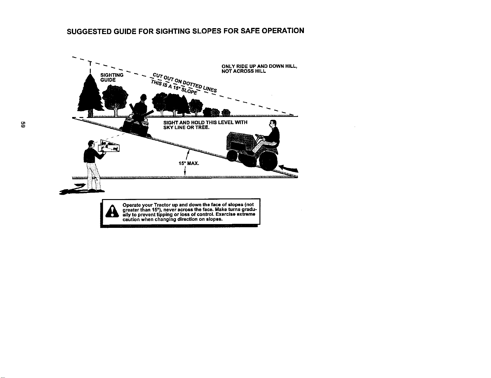
SUGGESTED GUIDE FOR SIGHTING SLOPES FOR SAFE OPERATION
GUIDE
ONLY RIDE UP AND DOWN HILL,
NOT ACROSS HILL
O1
_D
I_ Operate your Tractor up and down the face of slopes (not I
I
greater than 15°), never across the face. Make turns gradu-
I
ally to prevent tipping or loss of control. Exercise extreme
caution when changing direction on slopes.

Forrepair of major brand appliances in your own home...
no matter who made it, no matterwho soldit!
1-80O-4-MY-HOME sM_ytimo,dayo,.ight
(1-800-469-4663)
www.sears.com
To bringin productssuch as vacuums,
lawn equipment and electronicsfor repair,callfor
the locationofyour nearest Sears Parts & Repair Center.
1-800-488-1222 _ime,_ayor night
1-888-SU-HOGAR _"
(1-888-784-6427)
www.sears.com
For the replacement parts, accessoriesand owner's manuals
that you need to do-it-yourself, call Sears PartsDirect sM!
1-800-366-PART 6 a.m.- 11 p.m. CST,
(1-800-366-7278) 7daysa week
www.sears.com/partsdirect
To purchase or inquireabouta Sears Service Agreement:
1-800-827-6655
7 a,m. - 5 p,m. CST, Mon, - Sat,
Pare pedir servicio de reparacibn a domicilio, Au Canada pour service en fran_ais:
y pare ordenar piezas con entrega a domicilio: 1.877.LE.FOYER s-
(1-877-533_937)
.SEARS
H°meCentml ® ]
® Sears, Roebuck and Co.
® Registered Trademark Ira Trademark of Seam, Roebuck and Co.
® Marca Registrada / ;u Matte de Fdbrica de Sears, Roebuc_ and Co.
178528 2.7.01 JH Printed in U,S.A.


