
1
Owner’s Manual
HDMI over IP 4K Extender Transmitter
with PoE: B162-001-POE
HDMI over IP 4K Extender Receiver
with PoE: B162-100-POE
1111 W. 35th Street, Chicago, IL 60609 USA • tripplite.com/support
Copyright © 2021 Tripp Lite. All rights reserved.
Este manual está disponible en español en la página de Tripp Lite: tripplite.com/support
Ce manuel est disponible en français sur le site Web de Tripp Lite : tripplite.com/support
WARRANTY REGISTRATION
Register your product today and be
automatically entered to win an ISOBAR
®
surge protector in our monthly drawing!
tripplite.com/warranty

2
Table of Contents
1. FCC Information 3
2. User Notice 3
3. Package Contents 3
4. Introduction 4
5. Product Features 4
6. Getting Started 7
7. Hardware Setup 8
7.1 Components 8
7.2 Mounting the Device 11
7.3 Connecting the Device 12
8. Panel Operation 14
8.1 Overview 14
8.2 Status LEDs 14
8.3 Panel Controls 15
8.4 Assigning Sources 16
Using the Device Panel
9. Management 16
9.1 Overview 16
9.2 Looking Up the Login IP Address 16
9.3 Logging In and 17
Configuring DVOE Manager
9.4 The Main Screen 20
9.4.1 Apply/Auto Apply 21
9.5 Assigning Sources Using 21
DVOE Manager
9.6 Configuring and Setting Up 24
a Video Wall
9.6.1 Creating a Video Wall Layout 24
9.6.2 Editing a Video Wall Layout 26
9.6.3 Editing a Preview 27
9.7 Profile 27
9.7.1 Creating a Profile 28
9.7.2 Editing, Deleting and 29
Disconnecting a Profile
9.7.3 Select/Apply a Profile 30
9.7.4 Setting Up Profile Schedules 30
9.8 Managing B162 Devices 32
9.8.1 Checking B162 Status 32
10. System Settings 33
10.1 Overview 33
10.2 General Settings 33
10.3 Transmitter Settings 34
10.4 Receiver Settings 36
10.5 Batch Configuration 38
10.6 Maintenance 39
10.6.1 Upgrading Device Firmware 39
10.6.2 Synchronizing All Devices 39
10.6.3 Backing Up Device Settings 40
10.6.4 Restoring Device Settings 40
10.6.5 Recovery Mode 41
10.7 Account Settings 41
11. CLI Commands 42
11.1 Overview 42
11.2 Before You Start 42
11.3 Executing Commands 43
11.4 Commands 44
11.4.1 Guidelines 44
11.4.2 Switching Sources 44
` 11.4.3 Switching Video, USB, 45
RS-232 and/or IR Paths
11.4.4 Disabling Video, USB, 45
RS-232 and/or IR Paths
11.4.5 Displaying Port-Switching Alerts 46
11.4.6 Looking Up System Settings 46
11.4.7 Configuring Video Wall Settings 47
11.4.8 Muting Receivers or Video Walls 47
11.4.9 Disabling a Video Output 48
11.4.10 Enabling or Disabling a 48
Receiver’s OSD Display
11.4.11 Configuring EDID Mode 49
11.4.12 Rebooting the B162 Units 49
11.4.13 Setting the Baud Rate 50
11.4.14 Displaying Device Status 50
12. Important Safety Instructions 51
12.1 General Safety Instructions 51
12.2
Rack-Mounting Safety Instructions
51
13. Specifications 52
14. Supported Browsers 53
15. Warranty and Registration 54

3
1. FCC Information
FCC Notice, Class A
This device complies with part 15 of the FCC Rules. Operation is subject to the following two conditions: (1) This device may
not cause harmful interference, and (2) this device must accept any interference received, including interference that may
cause undesired operation.
Note: This equipment has been tested and found to comply with the limits for a Class A digital device, pursuant to part 15 of
the FCC Rules. These limits are designed to provide reasonable protection against harmful interference when the equipment
is operated in a commercial environment. This equipment generates, uses, and can radiate radio frequency energy and, if
not installed and used in accordance with the instruction manual, may cause harmful interference to radio communications.
Operation of this equipment in a residential area is likely to cause harmful interference in which case the user will be required
to correct the interference at his own expense. The user must use shielded cables and connectors with this equipment. Any
changes or modifications to this equipment not expressly approved by Tripp Lite could void the user’s authority to operate
this equipment.
2. User Notice
All information, documentation, and specifications contained in this manual are subject to change without prior notification by
the manufacturer. The manufacturer makes no representations or warranties, either expressed or implied, with respect to the
contents hereof and specifically disclaims any warranties as to merchantability or fitness for any particular purpose. Any of the
manufacturer’s software described in this manual is sold or licensed as is. Should the programs prove defective following their
purchase, the buyer (and not the manufacturer, its distributor, or its dealer), assumes the entire cost of all necessary servicing,
repair and any incidental or consequential damages resulting from any defect in the software.
The manufacturer of this system is not responsible for any radio and/or TV interference caused by unauthorized modifications
to this device. It is the responsibility of the user to correct such interference. The manufacturer is not responsible for any
damage incurred in the operation of this system if the correct operational voltage setting was not selected prior to operation.
PLEASE VERIFY THAT THE VOLTAGE SETTING IS CORRECT BEFORE USE.
3. Package Contents
B162-001-POE
• 4K HDMI over IP Extender Transmitter with PoE
• RS-232 Terminal Block
• 5V DC Power Adapter
• (4x) Foot Pads
• Quick Start Guide
Check to ensure all components are present and in good order. If anything is missing or was damaged in shipping, contact
your dealer.
Read this manual thoroughly, and follow the installation and operation procedures carefully to prevent any damage to the
product or to any other devices on the installation.
B162-100-POE
• 4K HDMI over IP Extender Receiver with PoE
• RS-232 Terminal Block
• 5V DC Power Adapter
• (4x) Foot Pads
• Quick Start Guide

4
4. Introduction
5. Product Features
Lightweight Compression with Ultra-Low Latency
• Delivers visually lossless high-quality video up to 4K @ 30 Hz (4:4:4).
• Ensures stunning quality video using advanced video lossless compression technology.
• Optimum EDID settings for smooth power-up, high-quality display and the best video resolution across different screens.
• Offers different levels of video compression rate, including Smooth, Balance and High Quality, for users to choose depending
on practical usage.
Power over Ethernet Support
• Place the unit anywhere, including ceilings, without having to install additional power cabling and outlets.
Limitless Scalability and Flexibility
•
Extends AV connections from a simple point-to-point to a multipoint-to-multipoint setup via LAN without distance limitations.
• Offers multi-functionality in extender, splitter, matrix switch, video wall and daisy-chain applications.
• Mix and match the latest 4K displays. Built-in scaler automatically scales up incoming video signal to match the maximum
resolution of the connected display devices.
Collaboration with Control System
•
Integrated solution - compatible with Control System, allowing users to operate B162 extender directly via CLI Telnet or
RS-232 protocol.
•
Effortless operation - one click to operate display, projector, source device and related equipment effectively via touch panel
and keypad.
The Tripp Lite B162 HDMI over IP Extenders deliver visually lossless 4K signals with low latency over long distance via a
standard Gigabit Ethernet switch.
Tripp Lite’s solution is designed to address the challenges that system integrators encounter when implementing AV over IP
solutions. It is an effective, easy-to-use and economical digital signage solution with the following features and advantages:
• Limitless scalability and flexibility
• No complicated IP setup
• No additional server PCs or software required
• Go further for less with daisy-chaining
• Convenient integration and installation
Engineered to meet today’s demands of large-scale, multi-display 4K signal transmission and designed for easy setup and
operation, the B162 HDMI over IP Extenders are ideal for a wide range of environments, such as trade shows, airports,
university campuses, conference centers and shopping centers.

5
5. Product Features
Note:
• B162 PoE extenders can be installed in combination with PoE Ethernet switches to reduce power cabling and additional
power outlets.
Spontaneous Scheduling Management
• Offers a user-friendly scheduling management function for users to pre-plan the display schedule.
• Provides robust and intuitive scheduling management options to help users manage all events in
the calendar and set events to one-minute intervals.
• Integrates all B162 units to arrange the profile by grouping individual receivers or video walls.
• Multiple profiles can be arranged to play in any order over a selected period.
No Complicated IP Setup
• Simple configuration that requires no extensive IT experience or extra learning.
• Effortlessly switches among input sources via top-panel push buttons.
6
5. Product Features
Web GUI-Based Management: No Additional Server PCs
or Software Required
• Simple access – users can use the browser or IP address to link directly to the DVOE Manager.
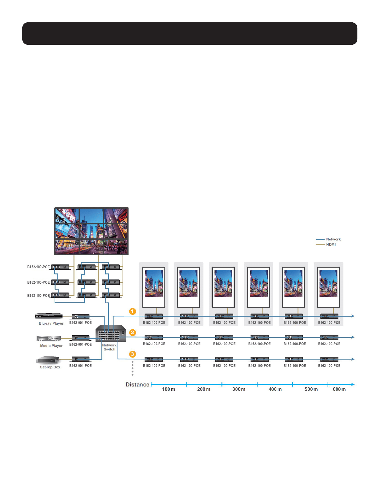
Go Further For Less with Daisy-Chaining
• Connects multiple displays through a single port to utilize every port of the Ethernet switch and maximize its value.
• Easily expandable – cabling and system deployment is easy with no huge Ethernet switches and fewer cables needed.
• Recommended for large-scale deployment covering hundreds of meters, such as hotel facilities, airports, university
campuses, stations, shopping malls and exhibition centers.
Note:
• Depending on your network architecture, we recommend daisy-chaining up to 30 units.
• For daisy-chain installation setup, only the first level supports PoE. All B162 units connected on the second level or above
will need a power adapter.

7
5. Product Features
Video Wall Support
• Supports up to 8 x 8 video wall (64 displays).
• Supports horizontal or vertical (90° and 270° rotation) display orientation.
• Easily switches layout profiles, preview and drag-and-drop video sources via the intuitive web GUI.
Note: If you experience issues related to your network architecture, please contact Tripp Lite for support.
Embedded / De-Embedded Audio Support
• Separate audio signal can be embedded into the HDMI stream (B162-001-POE only).
• Audio stream can be extracted from the HDMI stream and delivered as a separate audio signal (B162-100-POE only).
Multiple Control Channels
• Multiple control methods – the system can be managed via Ethernet or top-panel push buttons.
• USB Connectivity - USB port (USB 2.0) allows connection of devices, such as keyboard, mouse, flash drive,
printer and other USB peripherals.
Note: Each B162 transmitter can be controlled by 4 USB touchscreens connected to B162 receivers.
• Bi-Directional IR Channel – IR transmission is processed one way at a time.
• RS-232 Channel – bi-directional RS-232 serial port allows for connection of peripherals, such as touchscreens and
barcode scanners.
6. Getting Started
Follow the steps below to install, connect, configure and get started with your B162 devices:
1. Decide your network architecture and configuration.
2. Mount your B162 devices on walls or racks. For more information, see Mounting the Device.
3. Connect the B162 devices to sources, displays, network and other hardware devices as required. For more information,
see the installation diagrams in Connecting the Device.
4. Use one of the following methods to assign input sources:
• Note: Skip this step if you have a point-to-point setup. In a point-to-point setup, source input is automatically assigned.
• Assign input sources using the device panel. For more information, see Assigning Sources Using the Device Panel.
• Assign input sources using DVOE Manager. For more information, see Logging In and Configuring DVOE Manager.

8
7.1 Components
Before proceeding to hardware setup:
•Review the safety information regarding the placement of this device in Important Safety Instructions.
•Do not power on the device until all necessary hardware is connected.
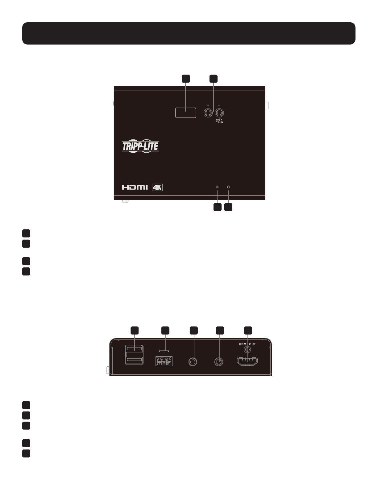
B162-001-POE Front View
1
HDMI Input – Connects an HDMI cable to the source device.
2
Audio Input – Connects an audio cable to the source device’s analog output.
Note: Does not support microphones.
3
Bi-Directional IR Port – Connects an IR receiver/transmitter to allow configuration using a remote control.
4
RS-232 Serial Port – Connects to a computer for serial control.
5
USB-B Port – Connects to the source device.
B162-001-POE Rear View
1
LAN Port with PoE – Connects a Gigabit Ethernet cable to the LAN.
2
DC Power Jack – Connects the DC Power Adapter to provide power to the transmitter.
7. Hardware Setup
AUDIO
IN
IR
USB
RS-232
Tx GND Rx
LAN
21 3 4 5
21
9
7. Hardware Setup
B162-001-POE Top View
1
ID Display Panel – Identifies the unit’s ID number.
2
Prev (+)/Next (-) Buttons – Assigns ID numbers on B162 devices,
and assigns the source video (transmitter) for the receiver.
3
Link LED – Lights orange to indicate the LAN Port 1 is connected to an Ethernet switch.
4
Power LED – Lights green to indicate the unit is receiving power.
B162-100-POE Front View
1
USB-A Ports – Connect virtual media or USB peripherals.
2
RS-232 Serial Port – Connects to a serial device.
3
Bi-Directional IR Port – Connects an IR receiver/transmitter
to allow configuration using a remote control.
4
Audio Output – Connects speakers.
5
HDMI Output – Connects an HDMI cable to the display.
ID NUMBE
R
POWER
LINK
4K HDMI Over IP Extender with POE
B162-001-POE
Transmitter
USB
RS-232
Tx GND Rx
IR
AUDIO
OUT
21 3 4 5
1 2
3 4
10
7. Hardware Setup
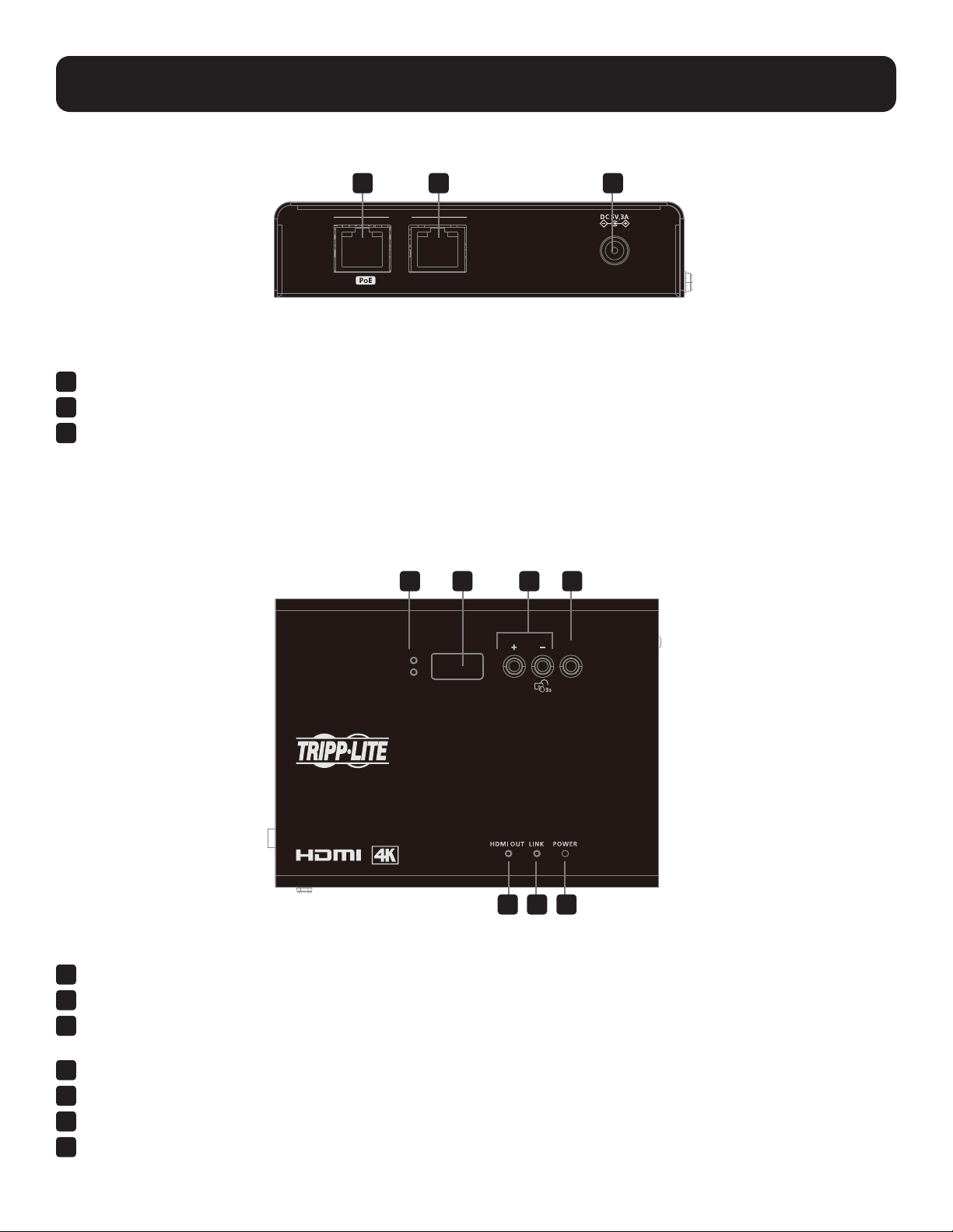
B162-100-POE Rear View
1
LAN 1 Port with PoE – Connects a Gigabit Ethernet cable to the LAN.
2
LAN 2 Port (no PoE) – Connects to another B162-100-POE with an Ethernet cable in a daisy-chain setup.
3
DC Power Jack – Connects the DC Power Adapter to provide power to the receiver.
B162-100-POE Top View
1
Tx/Rx LEDs – Light to indicate whether the displayed ID number is for the transmitter or receiver.
2
ID Display Panel – Identifies the transmitter’s or the receiver’s ID number.
3
Prev (+)/Next (-) Buttons – Assigns ID numbers on B162 devices,
and assigns the source video (transmitter) for the receiver.
4
Tx/Rx Switch Button – Press to switch control between the receiver and its corresponding transmitter.
5
HDMI Out LED – Lights orange to indicate a stable video output.
6
Link LED – Lights orange to indicate the LAN Port 1 is connected to an Ethernet switch.
7
Power LED – Lights green to indicate the unit is receiving power.
Tx
Rx
ID NUM BER
Tx / Rx
4K HDMI Over IP Extender with POE
B162-100-POE
Receiver
21 3 4
65 7
LAN
1
2
21 3
11
7. Hardware Setup
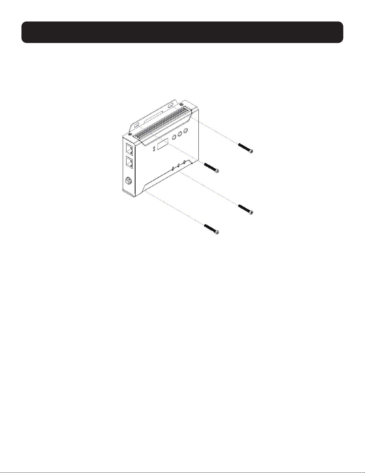
7.2 Mounting the Device
Wall Mount
Secure or hang the B162 unit on a wall using the built-in mounting brackets.
12
7. Hardware Setup
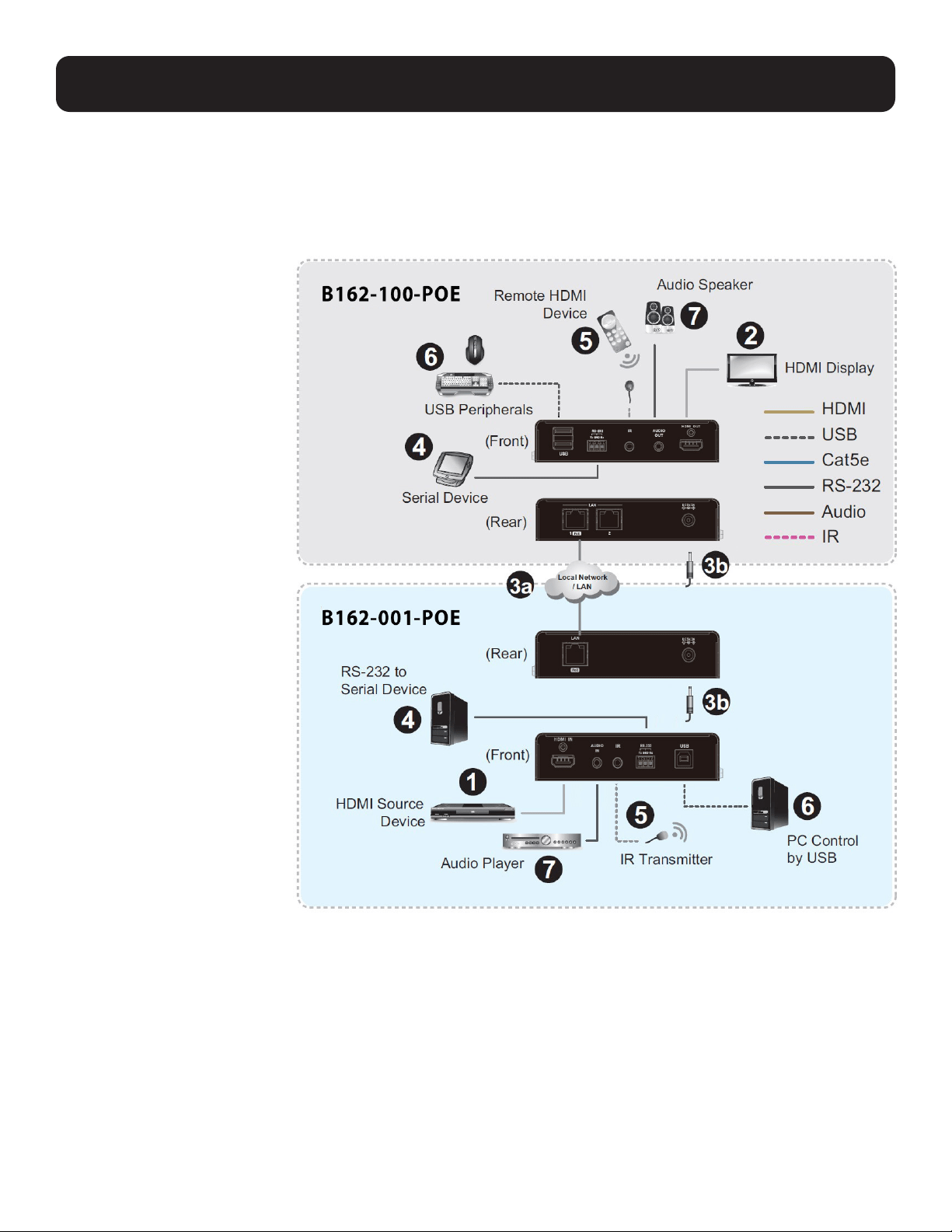
7.3 Connecting the Device
Follow the steps below to connect your B162 units with the hardware as required.
Note: For details on LED indicators to help you identify connection status or signal transmission, see Status LEDs.
1. Connect the transmitter’s
HDMI Input to the video
source device with a user-
provided HDMI cable.
2. Connect the receiver’s HDMI
Output to the video display
device with a user-provided
HDMI cable.
3. The diagrams to the right
illustrate a point-to-point
setup. Set up the B162 units
as follows:
Point-to-Point Setup
A. Connect one end of an
Ethernet cable to the LAN
Port on the transmitter
and the other end to the
LAN Port on the receiver.
B. Plug the power adapters
into the DC Power Jacks
on both units.
Multipoint-to-Multipoint
Setup
A. Install the transmitter and
the receiver to the same
LAN by connecting their
LAN Ports to an Ethernet
switch using Ethernet
cables.
B. The units can be powered on
through an Ethernet cable if
they are connected to a
PoE-supported Ethernet
switch. Alternatively, plug the
power adapters into the DC Power Jacks on both units.
Note: When power is available from both the power adapter and the Ethernet cable (PoE), the supply from the power
adapter will receive priority.
4. (Optional) To bypass RS-232 signals, connect your computer to the RS-232 Serial Ports on the units.
5. (Optional) To bypass IR signals, plug the IR Receiver into the Bi-Directional IR Port on the transmitter or receiver, depending
on where you wish to operate the remote control and the IR Transmitter.
6. (Optional) To use a keyboard/mouse, connect those USB peripherals to the receiver’s USB-A ports and your computer to
the transmitter’s USB-B port.
7. (Optional) Connect audio devices to the transmitter’s Audio Input and the receiver’s Audio Output.

13
7. Hardware Setup
Notes:
• The IR, RS-232 and USB signal transmissions are disabled by default. To enable them, go to System
Settings>Receiver>IR/RS232 or USB in DVOE Manager and select the signal source.
• Each transmitter can be controlled by 4 USB touchscreens connected to receivers.
• To receive HDMI audio on the transmitter, make sure to configure the following in DVOE Manager:
o Go to System Settings>Transmitter>Audio In, and change the setting to HDMI.
o To receive 5.1 or 7.1 surround sound on the receiver:
- Go to System Settings>Transmitter, access the transmitter’s configuration window, and set EDID to Manual.
- From DVOE Manager’s preview area, click the “three dots” (…) icon,
and select EDID to allow transmission of the receiver’s EDID to the transmitter.

14
8. Panel Operation
8.1 Overview
This chapter provides information on panel LEDs and instructions to operate the B162 units using the panel buttons.
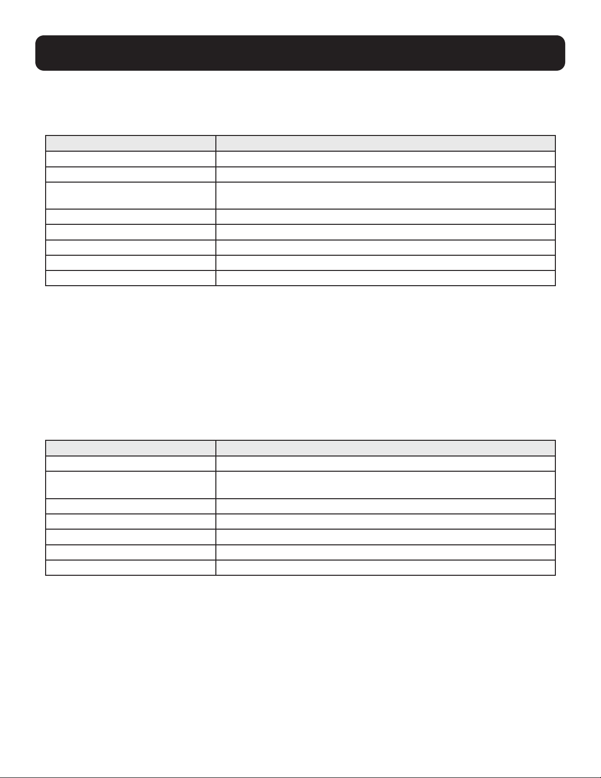
8.2 Status LEDs
Both the transmitter and receiver have front-panel LEDs that indicate their operating and power status.
LED Indicator Description
Power Lights green Device is powered on
Off Power is off
LINK Lights orange LAN is connected
Off LAN is not connected
HDMI Out Lights orange Video output is stable
Blinks orange Video output is unstable
Off Video output is not being transmitted
RJ45 Connector (Left LED) Lights orange Data is being transmitted at 100 Mbps
Lights green Data is being transmitted at 1000 Mbps (1 Gbps)
RJ45 Connector (Right LED) Lights green LAN is connected; no data is being transmitted
Blinks green LAN is connected; data is being transmitted

15
8.3 Panel Controls
1. Tx/Rx LEDs – Indicate whether the displayed ID number is for the transmitter or receiver.
2. ID Number:
o Transmitter: Identifies its ID number.
o Receiver:
- Identifies its ID number or the transmitter’s ID number when the panel control is switched to Tx.
- If the ID number exceeds 3 digits, letter A, b, c, d, E and F are used to replace the first 2 digits:
• A= 10, A00 ~ A99 to display ID number 1000 ~ 1099
• B= 11, b00 ~ b99 to display ID number 1100 ~ 1199
• C= 12, c00 ~ c99 to display ID number 1200 ~ 1299
• D= 13, d00 ~ d99 to display ID number 1300 ~ 1399
• E= 14, E00 ~ E99 to display ID number 1400 ~ 1499
• F= 15, F00 ~ F99 to display ID number 1500 ~ 1599
o ID Number blinks to indicate it is being used by another B162 device.
3. Up (+)/Down (-) Buttons:
a. Assign ID numbers on the devices.
b. Assign the source video (transmitter) for the receiver.
4. Tx/Rx Switch Button – Press to switch control between a receiver and its corresponding transmitter.
Notes:
• The B162 unit automatically locks its panel when it idles for 1 minute. To unlock, press and hold the Down button
for 3 seconds.
• Tx/Rx LEDs and Tx/Rx Switch button are available only on B162-100-POE receivers.
8. Panel Operation
ID NUMBE
R
POWER
LINK
4K HDMI Over IP Extender with POE
B162-001-POE
Transmitter
Tx
Rx
ID NUM BER
Tx / Rx
4K HDMI Over IP Extender with POE
B162-100-POE
Receiver
2 321 3 4

16
8. Panel Operation
9. Management
8.4 Assigning Sources Using the Device Panel
1. Assign an ID number to each of your B162-100-POE devices:
a. On the B162-100-POE, make sure the control is switched to Rx, in which case the Rx LED lights up. If not, press the Tx/
Rx Switch button.
b. Use Prev (+) and Next (-) to assign an ID number to this receiver.
c. Repeat Steps 1a and 1b on each B162-100-POE.
2. For a matrix setup, assign an ID number to each B162-001-POE device:
a. On the B162-001-POE, use Prev (+) and Next (-) to assign an ID number to this transmitter.
b. Repeat Step 2a on each B162-001-POE.
3. Assign source inputs to your B162-100-POE.
a. Press the Tx/Rx Switch button to switch control to Tx, in which case the Tx LED lights up.
b. Use Prev (+) and Next (-) to assign a source input to this receiver.
c. Repeat Steps 3a and 3b on each B162-100-POE.
9.1 Overview
B162 HDMI over IP Video Extenders can be remotely and centrally managed using a built-in utility program, the DVOE
Manager. Accessed through a web browser, this utility provides a central platform that allows you to do the following:
• Configure transmitter and receiver settings
o See Transmitter Settings and Receiver Settings
• Monitor transmitter and receiver statuses
o See Checking B162 Statuses
• Create display templates
o See Creating a Video Wall Layout
9.2 Looking Up the Login IP Address
Follow the steps below to download the IP Installer utility and use it to look up your transmitter’s IP address:
1. Go to the following https://assets.tripplite.com/firmware/b064-ip-installer.zip
2. Unzip and execute the downloaded IP Installer. The Network Device IP Installer screen appears.
3. Click Enumerate to search for devices in the network. The detected devices are shown in Device List.
4. Use the IP address of any B162 transmitter to log into DVOE Manager.
5. Alternatively, you can obtain the IP address from the HDMI monitor connected to the B162 receiver. For more information,
see the installation diagrams in Connecting the Device.
9.3 Logging In and Configuring DVOE Manager
On a computer with web access, follow the steps below to log into DVOE Manager:
17
9. Management
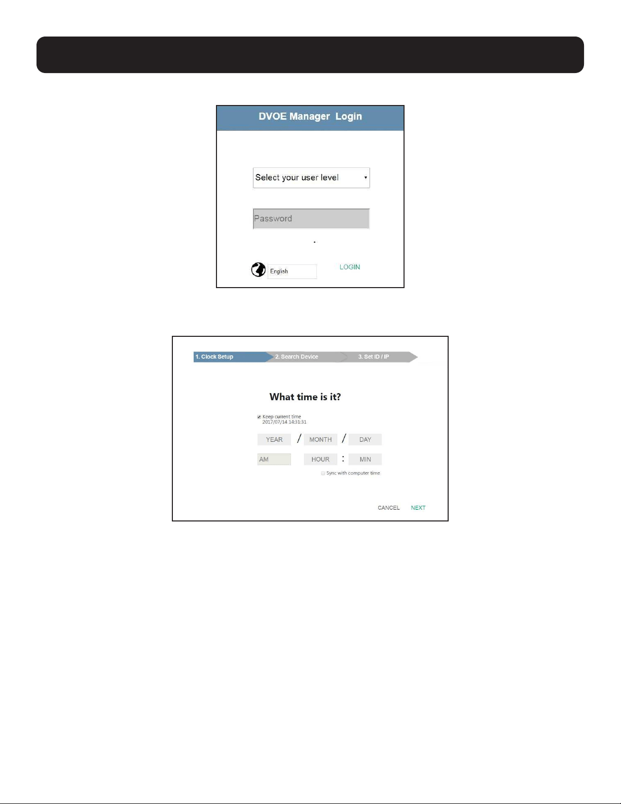
1. Open a web browser and type the IP address you obtained using IP Installer Utility. The following screen appears:
2. Select Administrator for User Level and type password for the Password field. The following screen appears upon initial login.
Note: If you are the administrator logging in for the first time, use the default password: password. For security purposes,
the system will prompt you to change the password. The new password must be different from your login password.
3. Select a date and time for the DVOE Manager using one of the following methods:
• To keep the current date and time settings, select Keep current time.
• To adopt the date and time settings of the endpoint used to access DVOE Manager, select Sync with computer time.
• To specify a different date and time, type the desired date and time in YYYY/MM/DD format.
18
9. Management
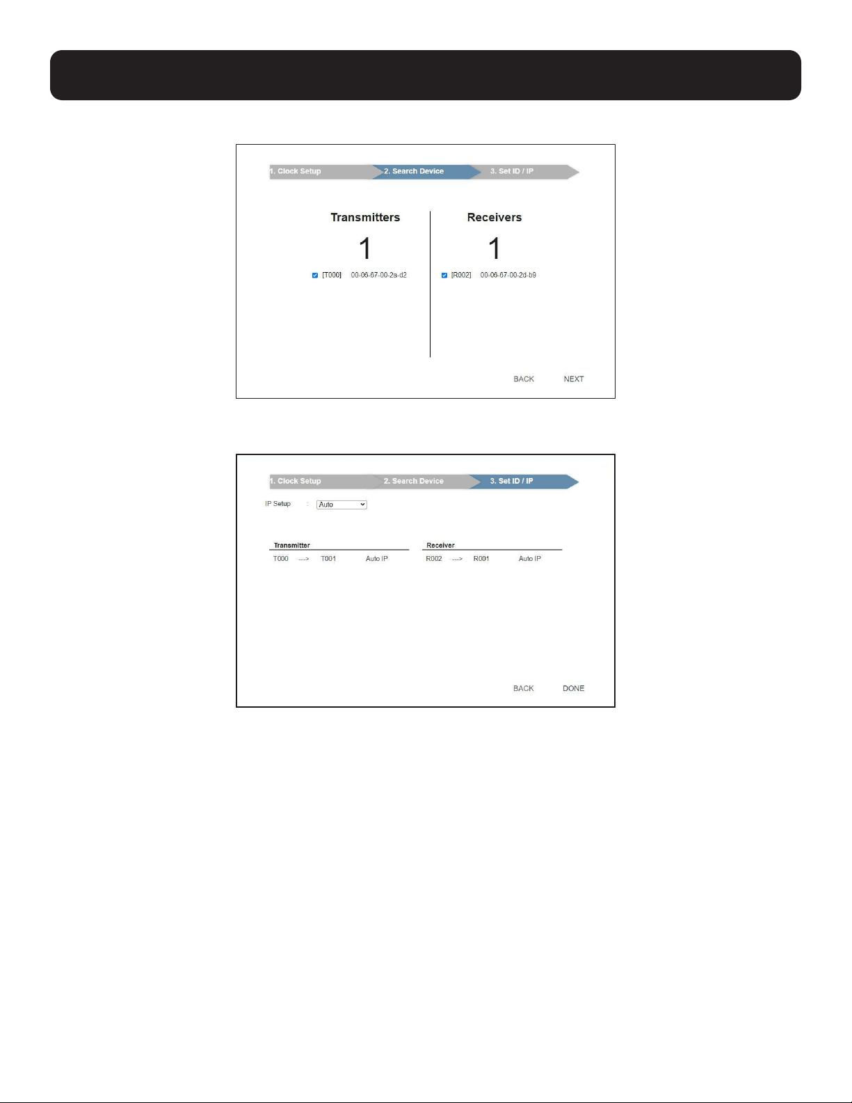
4. Click Next. The following screen appears. The setup wizard lists the B162 transmitters and receivers found in the network.
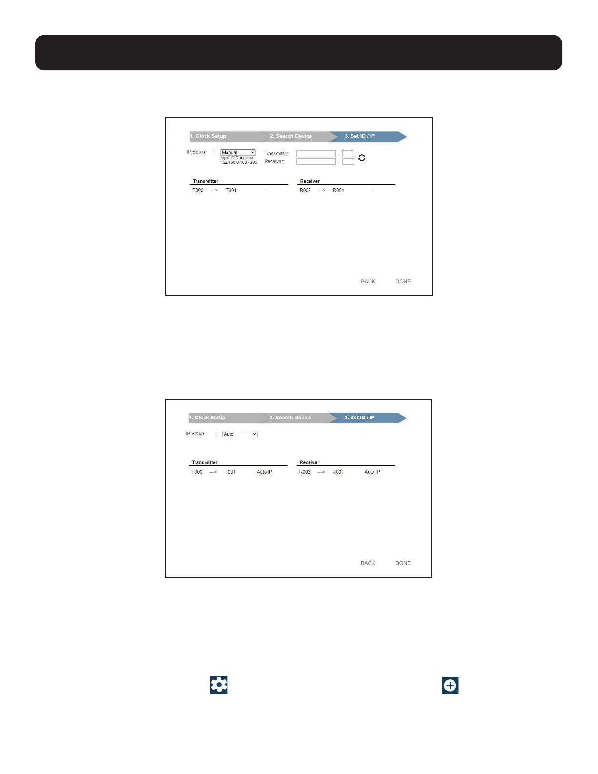
5. To configure device IP addresses, select the devices from the list and click Next. The following screen appears:
6. Click the IP Setup dropdown box to select a method for assigning IP addresses to the managed B162 devices.
• Auto – Select this option to have IP addresses automatically assigned by DVOE Manager.
• DHCP – Select this option to have IP addresses dynamically assigned by a DHCP server.
• Manual – Select this option to designate IP addresses for the managed video extenders. For details, see Step 7.
19
9. Management
7. To manually assign IP addresses, follow the steps below:
a. From the Set ID/IP page, select Manual for IP Setup. This screen appears:
b. In the Transmitter and Receiver fields, type valid IP address ranges.
c. Click Refresh to start assigning IP addresses.
d. When the assignment is complete, DVOE Manager displays the assigned IP addresses.
8. To reassign device IDs, click and type a new ID for the target B162 device.
9. Click Done. The DVOE Manager’s main screen appears.
Notes:
• For security reasons, Tripp Lite recommends changing the password at first login. For details on account settings, see
Account Settings.
• To access these settings again, click
from the DVOE Manager’s main screen, then click .

20
9.4 The Main Screen
You can access the following controls from the DVOE Manager’s main screen:
1
Previews for Video Walls and Receivers – Shows a preview of created video walls, individual video receivers and daisy-chain
setups. For details about creating video wall templates, see Creating a Video Wall Layout. For details about controls in a
preview, see Editing a Preview.
2
Preview Size – Drag the slider bar to adjust the size of preview windows.
3
Create/Edit Video Wall – Click to create or edit video wall templates. For details, see Assigning Sources Using DVOE
Manager.
4
OSD – Globally enables or disables panel control of the B162 devices used in managed video walls. To enable or disable
panel control for a single video wall, use the OSD setting for a preview window. For details, see Configuration Menu in
Editing a Preview.
5
Refresh – Refresh or update the daisy-chain status.
6
Auto Apply – Enables settings to be automatically applied to the devices.
7
Profile Schedule – Click to enter profile scheduling page. For more information, see Setting Up Profile Schedules.
8
System Settings – Access general settings, transmitter and receiver settings, firmware updates, backup and restore
settings, account settings and other system settings. For more details, see System Settings.
9
Log Out – Click to log out of DVOE Manager
10
Source List – Lists display sources and identifies each with its corresponding transmitter.
11
Profile Bar – Video wall profile for video wall display. For more information, see Profile.
9. Management
2
1
11
10
3 4 5 6 7 8
9
21
9. Management
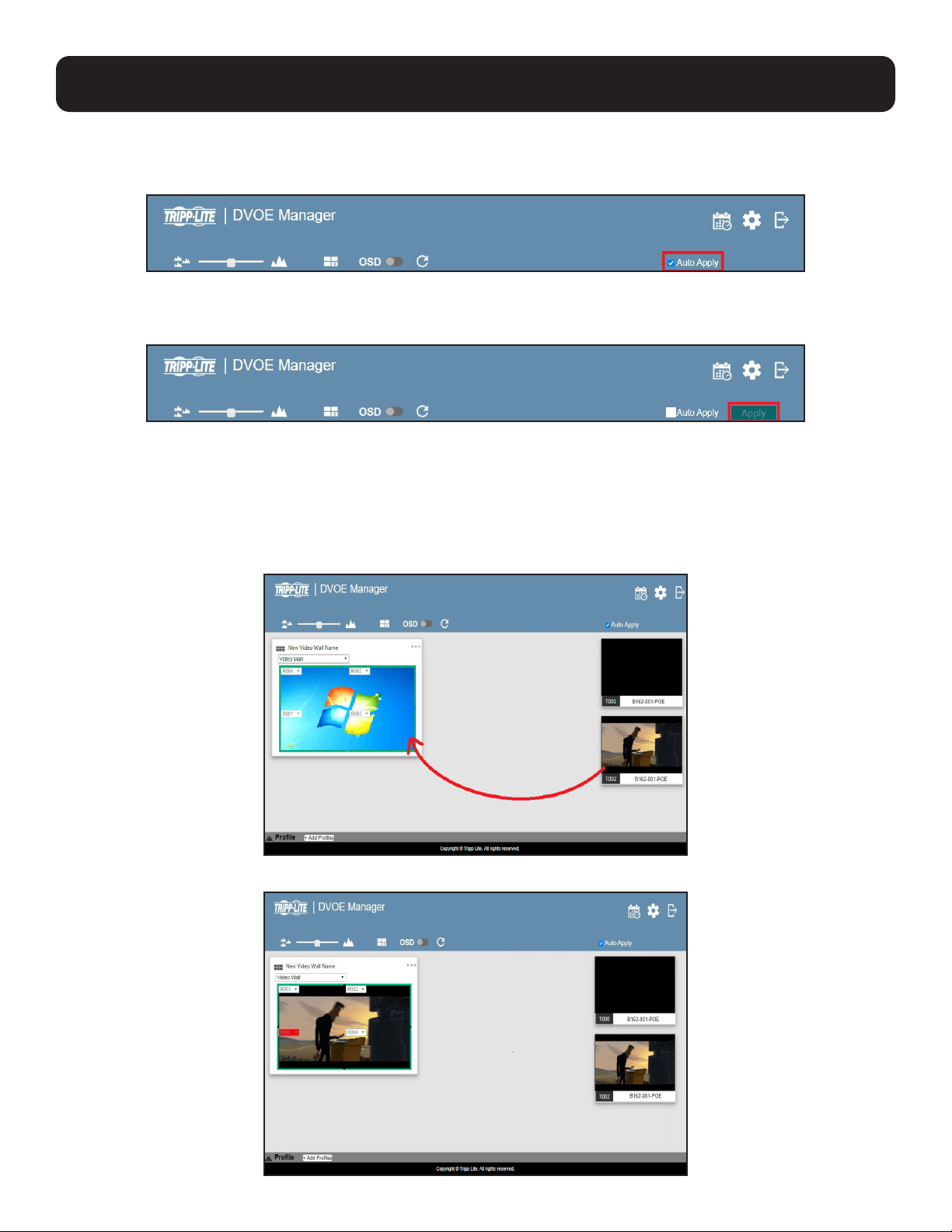
9.4.1 Apply/Auto Apply
If you wish to apply settings as you configure them, check Auto Apply.
Alternatively, if you wish to manually apply the settings, uncheck Auto Apply and use the Apply button. The button will light up
to show a change was made.
9.5 Assigning Sources Using DVOE Manager
Follow the steps below to assign input sources using DVOE Manager:
1. On the main screen, identify the source you wish to be assigned in the Source List and the preview video walls/receivers.
2. Select and drag the source to the preview video walls/receivers.
3. When there is a display issue from the connected receiver, the specific receiver will be indicated in red from the preview.
22
9. Management
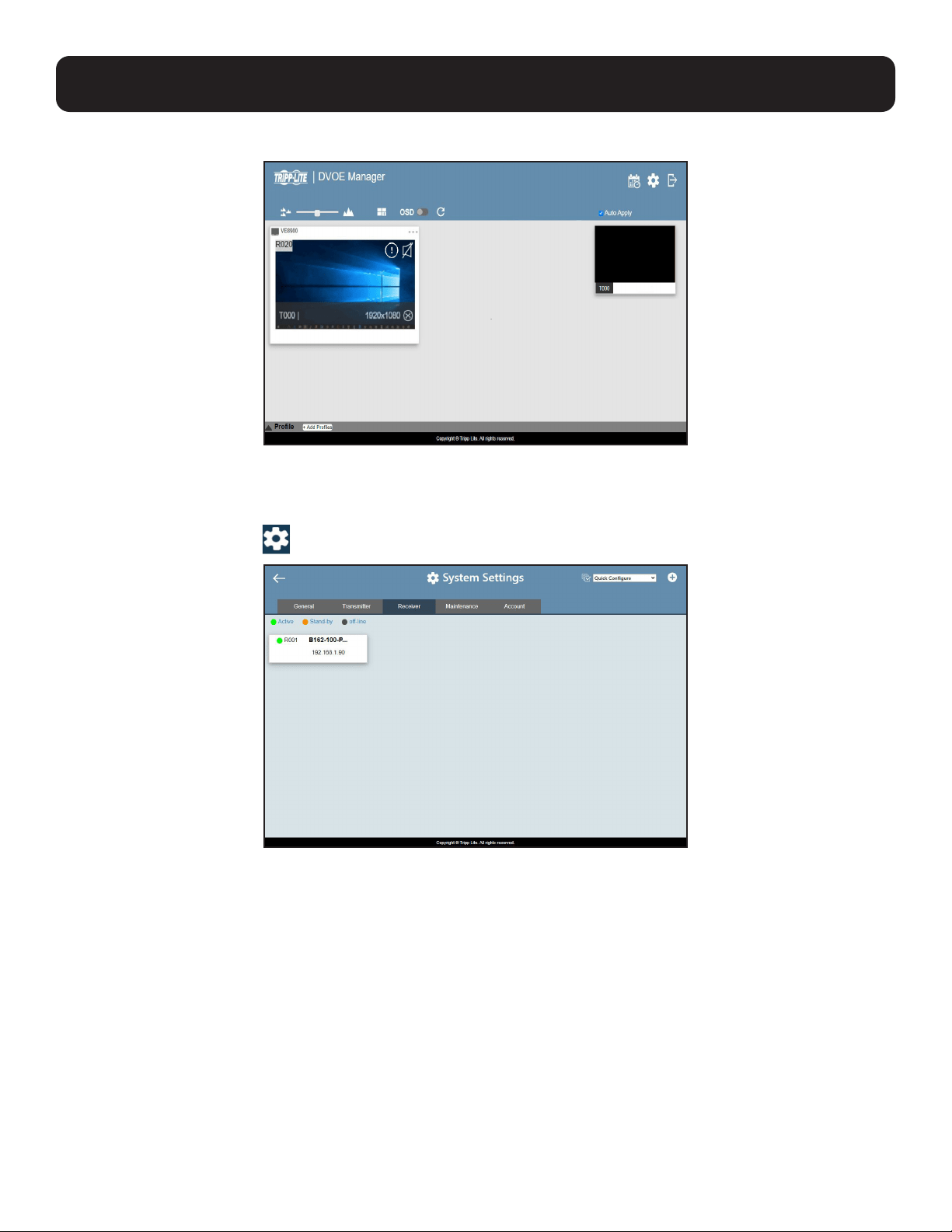
4. When there is a display issue from a single connected receiver, the preview is shown below.
Alternatively, you can go into system settings to assign sources there. Follow the steps below:
1. From the main screen, click
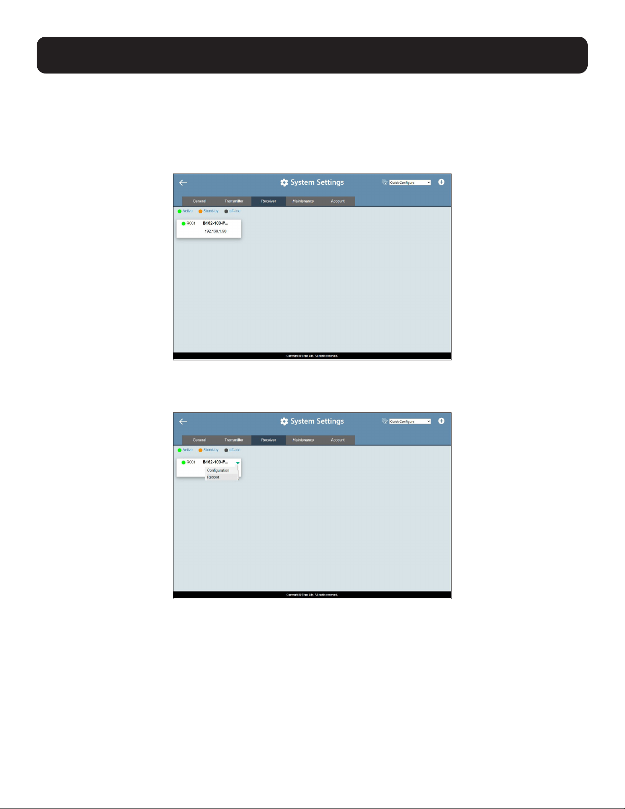
, and then click the Receiver tab. The managed B162-100-POE receivers appear.
23
9. Management
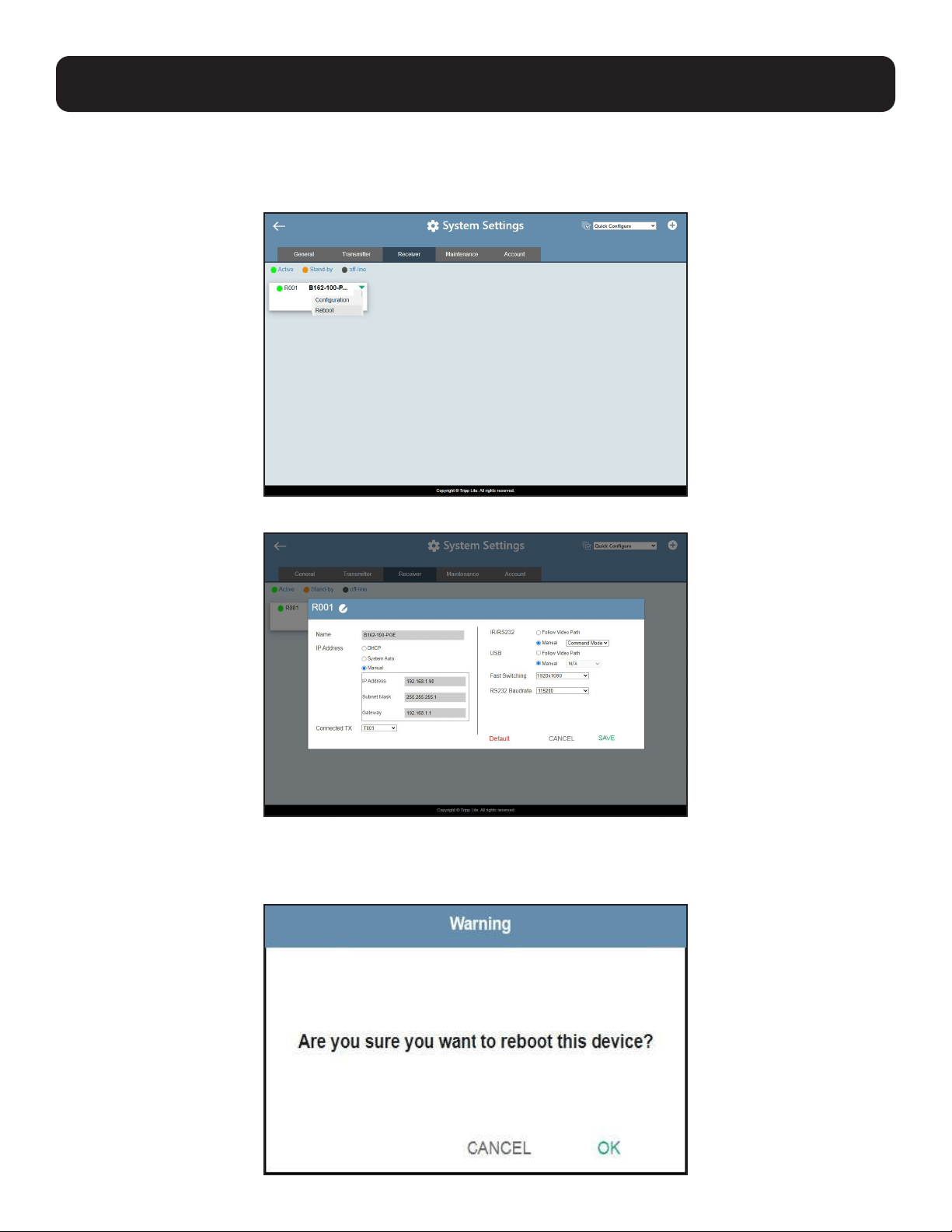
2. Assign a source for each of the B162-100-POE receivers.
a) Move the cursor to a receiver. A green arrow appears at the top right corner of the receiver preview window.
b) Click the green arrow. A dropdown menu appears.
c) From the dropdown menu, click Configuration. This window appears:
d) Click the Connected Tx dropdown arrow and select a Tx source.
e) Repeat steps 2a through 2d to assign sources for each of the receivers.
f) To reboot the B162 units, click the green arrow mentioned in step 2b, and click Reboot. This warning window appears:
24
9. Management
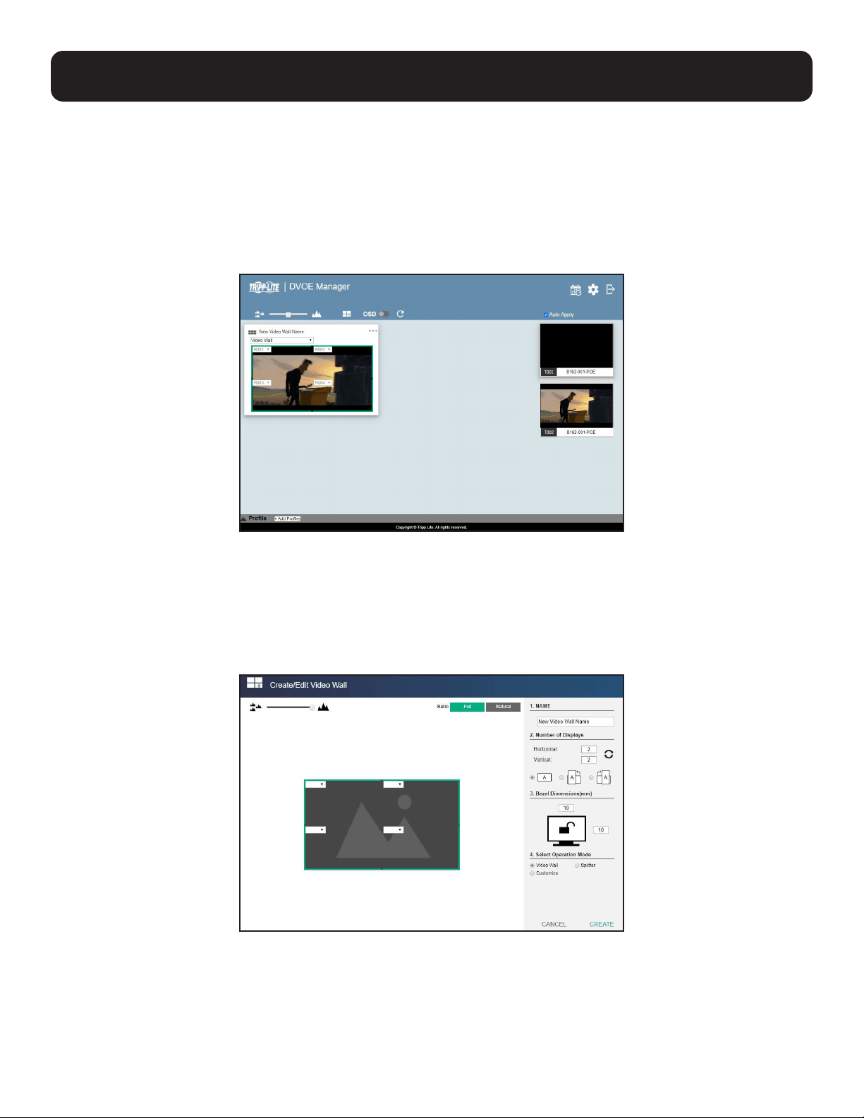
9.6 Configuring and Setting Up a Video Wall
To configure a video wall, follow the steps below.
1. Make sure you have created a video wall template for your specific needs. For detailed steps, see Creating a Video Wall
Layout.
2. From the DVOE Manager’s main screen, drag and drop input sources from the Source List onto the created video wall
layout. In the following example, the display source T002 is assigned to this video wall layout, which has 4 monitors,
R001 to R004, merged to form an enlarged display of one source video.
Note: For details on editing video wall settings, see Editing a Preview.
9.6.1 Creating a Video Wall Layout
1. To create a new layout, click Create/Edit Video Wall from the main screen. The following window appears. A preview of the
layout is shown in the middle.
25
9. Management
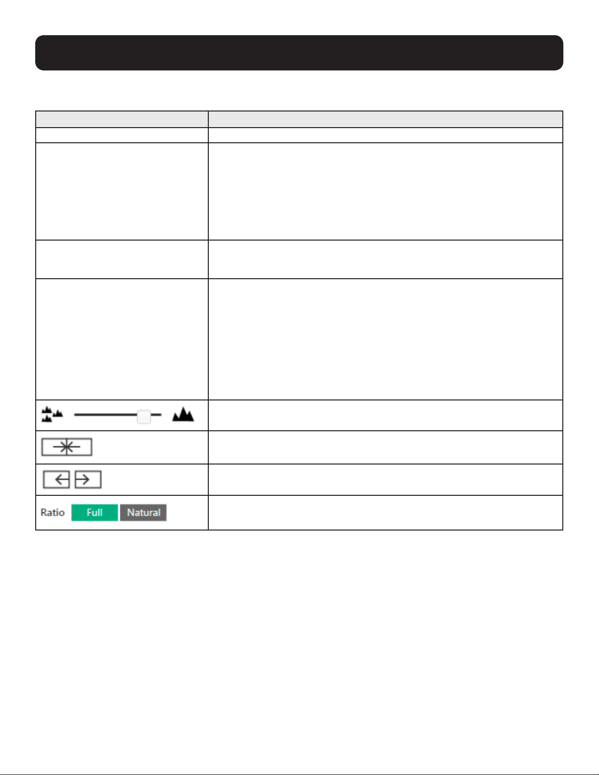
2. Configure your video wall layout as required. Use the preview to help you visualize the layout.
Control Description
Name of Video Wall Type the name of your video wall.
Number of Displays Define the following parameters.
Horizontal and Vertical: Click the dropdown boxes to select the number of displays
for your video wall. Click Refresh to show a preview of your configuration.
Display Orientation: Select horizontal or vertical display. A vertical display is either
a 90° clockwise or a 90° counter-clockwise rotation of the horizontal display.
Bezel Dimensions Type to specify the top/bottom and right/left widths of the monitor frame.
The value on the top is the total of the top and bottom bezel. The value on the
right is the total of the left and right bezel.
Operation Mode Select an operation mode for your video wall:
Video Wall: Select this option to set up a video wall.
Splitter: Select this option to set up a display of identical content on multiple
monitors.
Customized: Select this option to create a customized display. Click New layout
in the list to rename this template.
Click and hold the slider bar to enlarge or reduce the size of preview windows.
Use this button to merge displays. Click to select the desired monitors from the
layout preview and click the button to merge the monitors.
Use this button to separate already merged monitors. Select a merged monitor
from the layout preview, and then click the button.
Full: Click to display source videos in full extension.
Natural: Click to display source videos in their original aspect ratio.

26
9. Management
3. From the preview area, click the dropdown boxes to define the output receiver for each monitor. An already selected,
unavailable receiver is marked with an asterisk (*).
4. Click Create. The new video wall template is created.
9.6.2 Editing a Video Wall Layout
To edit a video wall layout from the DVOE Manager’s main screen, click the top right corner of the layout you wish to edit, and
then select Edit. For more details on video wall settings, see Creating a Video Wall Layout.
27
9. Management
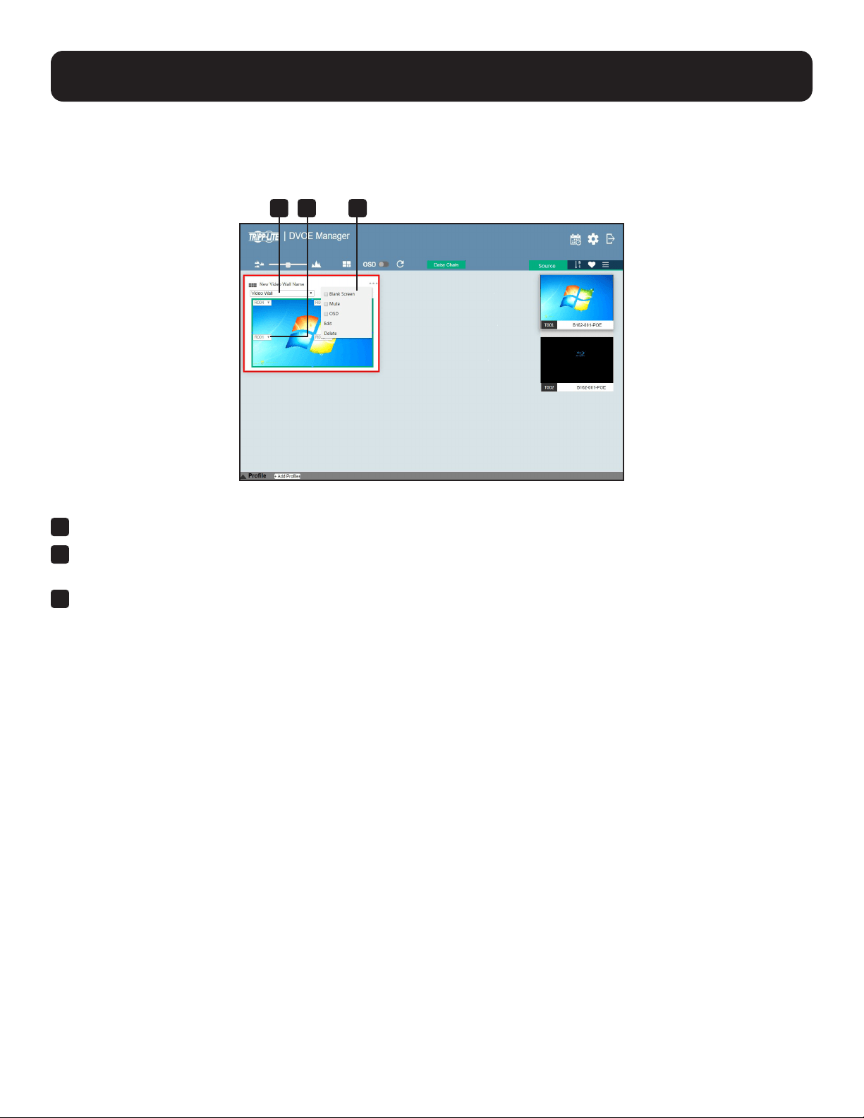
9.6.3 Editing a Preview
You can edit the following settings for a video wall layout:
1
Operation Mode – Click the dropdown list to select an operation mode.
2
Assigned Receiver – Displays the assigned receiver for the display. For an unmerged display, double-click the display to
open the settings page for the assigned receiver.
3
Configuration Menu – Click the top right corner to access the following controls:
o Blank – Disables the display on this video wall.
o Mute – Disables audio transmission to this video wall.
o OSD – Enables or disables the panel control of all B162 devices for this video wall.
o Edit – Click to access the video wall layout settings. For more details, see Creating a Video Wall Layout.
o Delete – Click to remove this layout from DVOE Manager. For a receiver, this option is only available when it is offline.
9.7 Profile
After configuring video receiver/video wall settings, if you find that you would like to keep the current settings, you can save it
as a profile. You can create different profiles and apply them manually, or you can set up profile schedules for switching video
displays at different times of a day, week or month.
2 31
28
9. Management
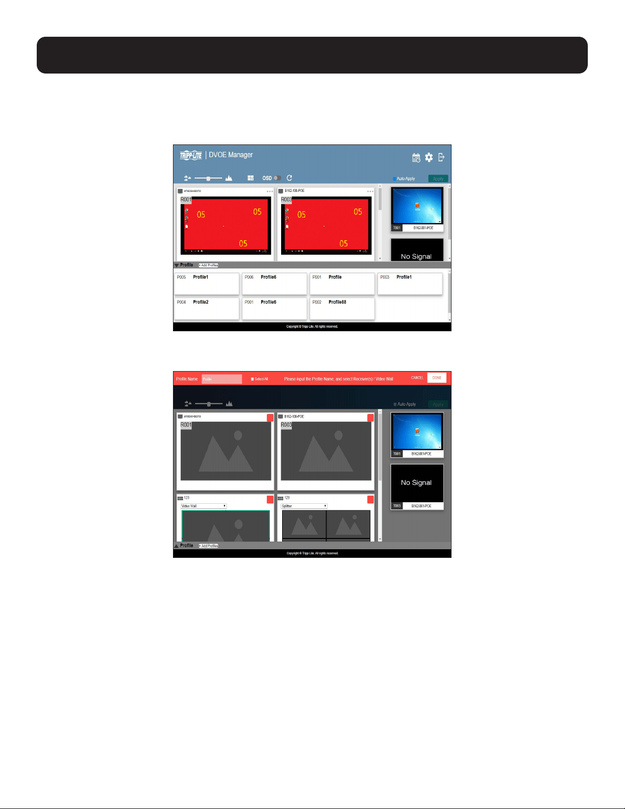
9.7.1 Creating a Profile
Follow the steps below to create a profile.
1. On the main screen, click the profile arrow on the profile bar for the profile list shown below:
2. Click +Add Profiles for the page below:
• Profile Name: Enter a profile name.
• Receivers/Video Walls: Select the receivers/video walls you wish to be in this profile by checking the orange box. Alternatively,
you can select all receivers/video walls by checking the Select All option.
3. Click Done to complete the configuration.
29
9. Management
9.7.2 Editing, Deleting and Disconnecting a Profile
On the profile list, you can edit, delete and disconnect profiles. Click to select the profile you wish to configure and a green
arrow will appear. Click the green arrow for a dropdown menu of edit, delete and disconnect options.
Edit
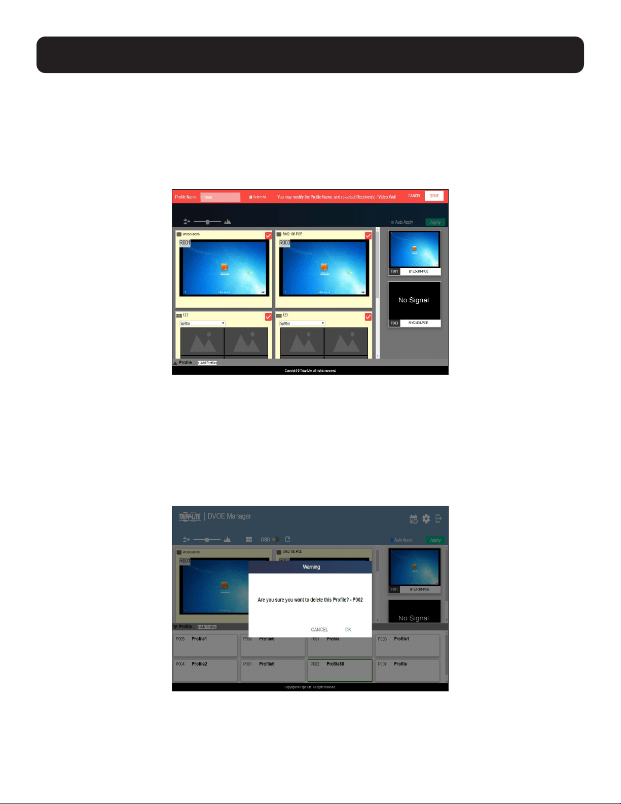
To edit the profile, click the Edit option:
• Profile Name: Enter a profile name.
• Receivers/Video Walls: Select/deselect the receivers/video walls you wish to be in this profile by checking/unchecking the
orange box. Alternatively, you can select/deselect all receivers/video walls by checking/unchecking the Select All option.
Click Done to complete editing.
Delete
To delete the profile, click the Delete option:
The system will ask if you would like to delete this profile. Click OK to proceed or click Cancel to cancel.
Disconnect
To disconnect the current profile from the video wall, click Disconnect. The video wall should go blank.

30
9. Management
9.7.3 Select/Apply a Profile
After creating the profile, you can apply the settings of the profile to the video displays. Follow the steps below to apply the settings:
1. Bring up the profile list.
2. Click to select a profile and a preview will be shown:
The video receiver/video wall selected in the profile will be displayed. If the current video receivers/video walls have a yellow
background, it indicates the video settings have not been applied. If the background is gray, it indicates the video receivers/
walls are not available. If the background is white, it indicates the settings are currently applied to the system.
3. Click Apply to apply the settings of the profile.
4. When applied, the video settings will be shown on the main screen.
9.7.4 Setting Up Profile Schedules
Follow the steps below to set up profile schedules:
1. On the main screen, click the profile schedule icon on the top right corner.
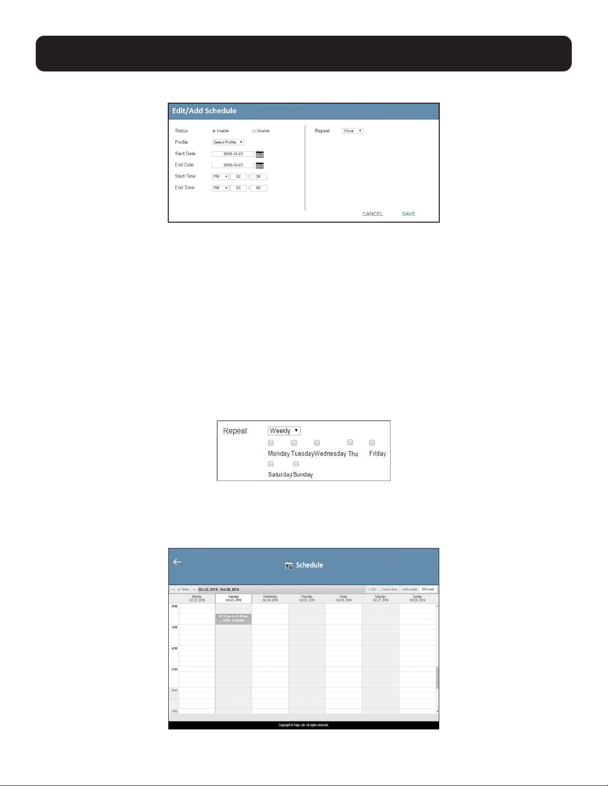
An example of the profile schedule screen (with nothing planned) is shown below:
On this page, you can
select to show current
schedule of either
• “1 day”
• “next 3 days”
• “work week”
• “full week”
31
9. Management
2. Click to select the day and time period to set up the schedule. An example is shown below:
3. Edit/add the schedule as required:
• Status: Enable or disable the schedule.
• Profile: Select a profile.
• Start Date: Select or enter a start date.
• End Date: Select or enter an end date.
• Start Time: Select or enter a start time.
• End Time: Select or enter an end time.
• Repeat: Select a repeat cycle for the schedule.
o Once: Select this option to run this schedule only once.
o Daily: Select this option to run this schedule every day.
o Weekly: Select this option to run this schedule every week.
You can also select which days you wish the schedule to run in a week. The option is shown below:
o Monthly: Select this option to run this schedule every month. You can also enter the days you wish the schedule to run in
a month, or enter a range(s) for the schedule to run. Follow the on-screen instructions on how to enter the schedule here.
4. Click Save to save the schedule. An example is shown below:
32
9. Management
9.8 Managing B162 Devices
9.8.1 Checking B162 Status
You can check the statuses of your B162 devices by clicking
,
from the main screen, and then the Transmitter or Receiver tab.
The status for a B162 device is indicated with a colored circle. See the table below for status indicators and the
corresponding descriptions.
Indicator Description
Green Device is connected and active
Orange Device is on standby
Gray Device is offline

33
10. System Settings
10.1 Overview
The System Settings page allows you to specify device date and time, configure settings of connected B162 devices, upgrade
device firmware and back up the DVOE Manager’s settings.
10.2 General Settings
The General tab contains the date, time and panel lock settings.
To access the General tab, click the , from the main screen, and then click the General tab.
• Date and time: Click and type the desired information and click Set to save the settings.
• Sync with computer time: If you wish to synchronize the time with the computer’s time, check the checkbox and click Set.
• Pop-Up OSD: When enabled, the OSD will be displayed when switching video sources. The OSD will not be displayed when
disabled.
• Video Quality: Click to select a video quality for display.
• Panel Lock:
o Select Permanent to lock the panel control of all connected B162 devices. To unlock the panel of a single B162 device,
uncheck the Enable checkbox.
o Select Auto to automatically lock the panel control of all connected B162 devices when it idles for 1 minute. To unlock
the panel of a single B162 device, press and hold the Down (-) button on the top panel for 3 seconds.
• Installation Wizard: Click the plus-sign icon on the top right corner to open the installation wizard. For details, see Logging In
and Configuring DVOE Manager.
Click Apply for the settings to take effect on the connected B162 devices.
34
10. System Settings
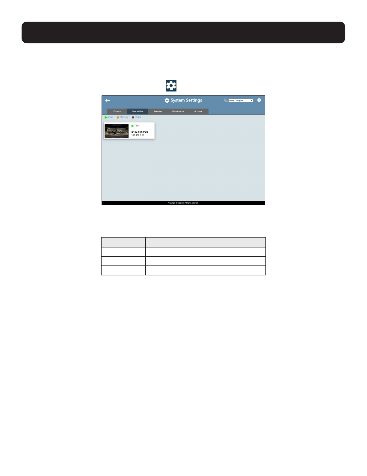
10.3 Transmitter Settings
The Transmitter tab displays the managed B162-001-POE transmitter devices and provides access to the settings. To access
transmitter settings, follow the steps below:
1. From the main screen, click the gear icon and then click the Transmitter tab. The managed B162-001-POE transmitters appear.
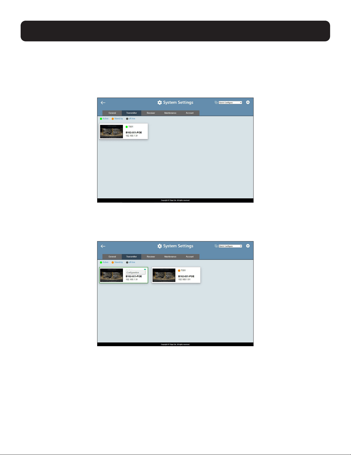
2. Move the cursor to a transmitter you wish to configure. A green arrow appears at the top right corner of the transmitter
preview window.
3. Click the green arrow. A dropdown menu appears.
35
10. System Settings
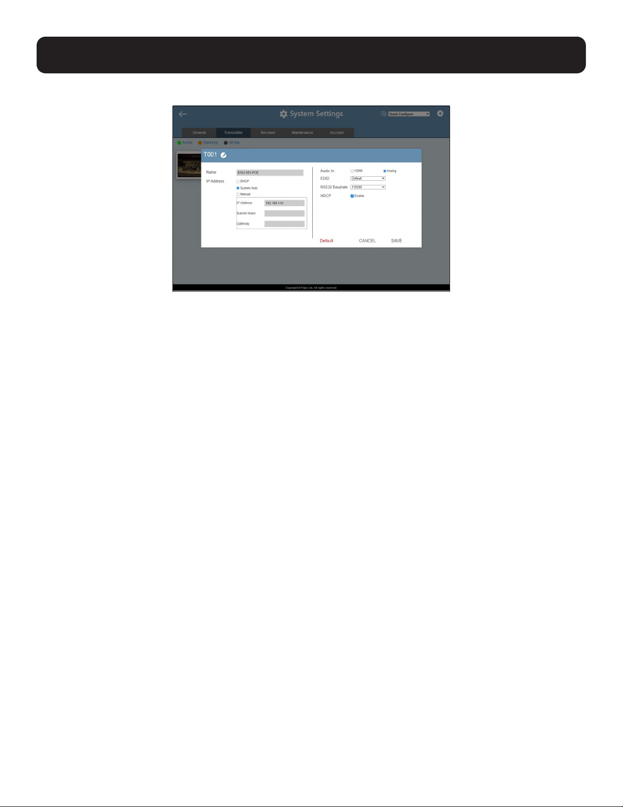
4. Click Configuration. This window appears.
5. Configure the settings as required.
• Name: Click to rename the transmitter.
• IP Address: Specifies how the transmitter obtains its IP address. By default, this field is set to System Auto.
o DHCP: Select this option to have the IP address automatically assigned by a DHCP server.
o System Auto: Select this option to have the IP address automatically assigned by the DVOE Manager.
o Manual: Select this option to designate an IP address for the transmitter. Manually type the IP Address, Subnet Mask
and Gateway for the device.
• Audio In: Select your audio signal type.
• EDID: After receiving EDID information from the connected display, the B162-001-POE analyzes this information and sets
up the input source. Select an EDID mode that suits your needs.
o Default: Sets up the input to an optimum configuration based on a predefined list of EDID.
o Auto: Sets up the input to the best resolution of the connected displays.
o Manual: Sets up the input to user’s configuration.
o Remix: Sets up the input to an optimum resolution of the connected displays.
• RS-232 Baud Rate: Select a suitable baud rate.
• HDCP: By default, HDCP is enabled for the B162 units.
• Default: Click to restore the transmitter’s settings to default.
6. Click Save to keep the changes.
36
10. System Settings
10.4 Receiver Settings
The Receiver tab displays the managed B162-100-POE receiver devices and provides access to the settings. To access receiver
settings, follow the steps below:
1. From the main screen, click the gear icon, and then click the Receiver tab. The managed B162-100-POE receivers appear.
2.
Move the cursor to a receiver you wish to configure. A green arrow appears at the top right corner of the receiver preview window
.
3. Click the green arrow. A dropdown menu appears.
37
10. System Settings
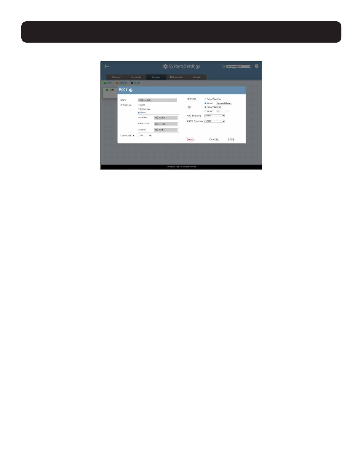
4. Click Configuration. This window appears.
5. Configure the settings as required.
• Name: Type to name the receiver.
• IP Address: Specifies how the receiver obtains its IP address. By default, this field is set to System Auto.
o DHCP: Select this option to have the IP address automatically assigned by a DHCP server.
o System Auto: Select this option to have the IP address automatically assigned by the DVOE Manager.
o Manual: Select this option to designate an IP address for the receiver. Manually type the IP Address, Subnet Mask and
Gateway for the device.
• Connected Tx: Defines the video source for this receiver.
• IR/RS-232: Sets the source for IR/RS-232 signals. By default, the IR and RS-232 are disabled (Manual > N/A).
o Follow Video Path: Select this option to receive IR/RS-232 signals from the transmitter (Connected Tx) where the
receiver obtains its video source.
o Manual: Use this setting to select a different source for obtaining IR/RS-232 signals.
• USB: Sets the source for the connected USB devices.
o Follow Video Path: Select this option to receive USB signals from the transmitter (Connected Tx) where the receiver
obtains its video source.
o Manual: Use this setting to select a different source for obtaining USB signals.
• Fast Switching: Click to define the resolution for fast switching. Note: For best results, Tripp Lite recommends setting this
field to the same resolution as your video source and make sure this setting is identical on all B162-100-POE receivers.
• RS-232 Baud Rate: Click to define the baud rate for the receiver.
• Default: Click to restore the receiver’s settings in this window to default.
6. Click Save to keep the changes.

38
10. System Settings
10.5 Batch Configuration
A batch configuration option is available for both Transmitters and Receivers. It appears on the top right corner of the page as
Quick Configuration. If you wish to adjust a particular setting for a group of devices, do the following:
1. Click Quick Configuration for a dropdown menu.
2. Select a setting you wish to configure. The available options for the dropdown menu will depend on whether you’re in
the Transmitter or Receiver settings. The interface will allow you to select which devices you wish to configure.
3. Check the devices you wish to configure or, if you wish to select all the devices on the list, check Select All (on the
top left-hand corner) and click Next. The Quick Configure window will appear and you can see each device’s status.
A dropdown menu is available at the bottom of the window for the configuration.
4. Select the desired setting and click Apply to apply the setting to all the devices.
39
10. System Settings
10.6 Maintenance
The Maintenance tab allows you to upgrade device firmware, back up transmitter and receiver layouts and restore devices to
previously backed up settings.
10.6.1 Upgrading Device Firmware
To upgrade firmware, follow the steps below.
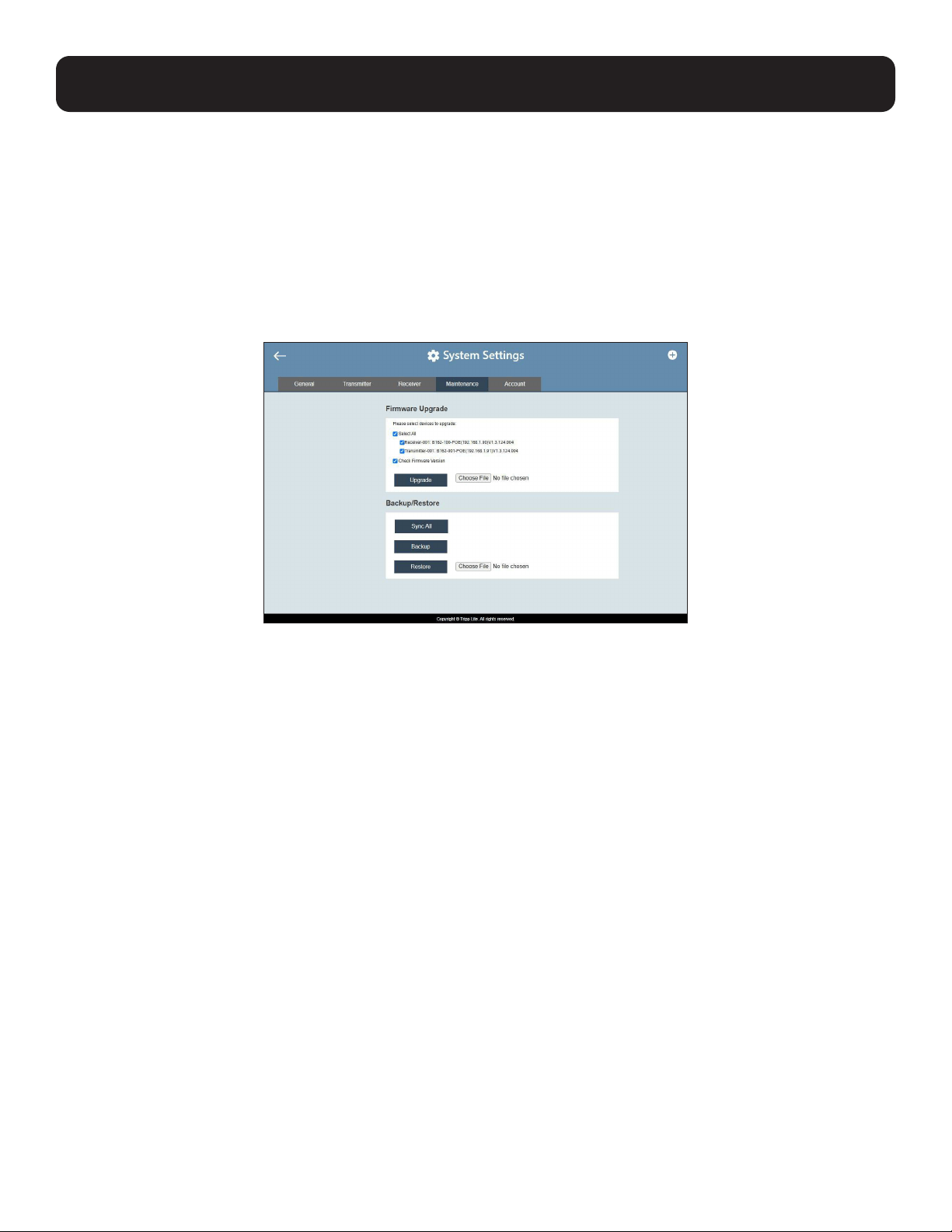
1. From the main screen, click the gear icon and click the Maintenance tab. The following screen appears. The Firmware Upgrade
section lists the detected transmitter and receiver devices and their firmware versions.
2. Click Choose File to locate a previously saved firmware file.
3. Click to uncheck any devices that do not require the upgrade.
4. By default, any upgrades that involve a version rollback will be ignored. To apply both upgrades and version rollbacks, uncheck
Check Firmware Version.
5. Click Upgrade to start upgrading.
10.6.2 Synchronizing All Devices
When you wish to add or replace devices, click Sync All for the system to recognize the added/replaced device.

40
10. System Settings
10.6.3 Backing Up Device Settings
You can export transmitter and receiver layouts for backup or migration purposes.
1. From the main screen, click the gear icon and then click the Maintenance tab. This screen appears:
2. Click Backup. A confirmation message appears when the backup is complete.
10.6.4 Restoring Device Settings
You can restore your DVOE Manager to a previously saved set of settings on transmitter and receiver layouts.
1. From the main screen, click the gear icon and then click the Maintenance tab. This screen appears:
2. Click Choose File to locate a previously saved settings file.
3. Click Restore to start overwriting the settings to the DVOE Manager. A confirmation message appears when the backup is
complete.

41
10. System Settings
10.6.5 Recovery Mode
Four conditions require Recovery Mode:
1. When a firmware upgrade is manually aborted.
2. When the mainboard firmware upgrade fails.
3. When the I/O firmware upgrade fails.
4. The unit is not powered on for an unknown reason.
To set the B162 units to recovery mode, do the following:
1. Press and hold the Prev (+) push button.
2. Power on the B162 units.
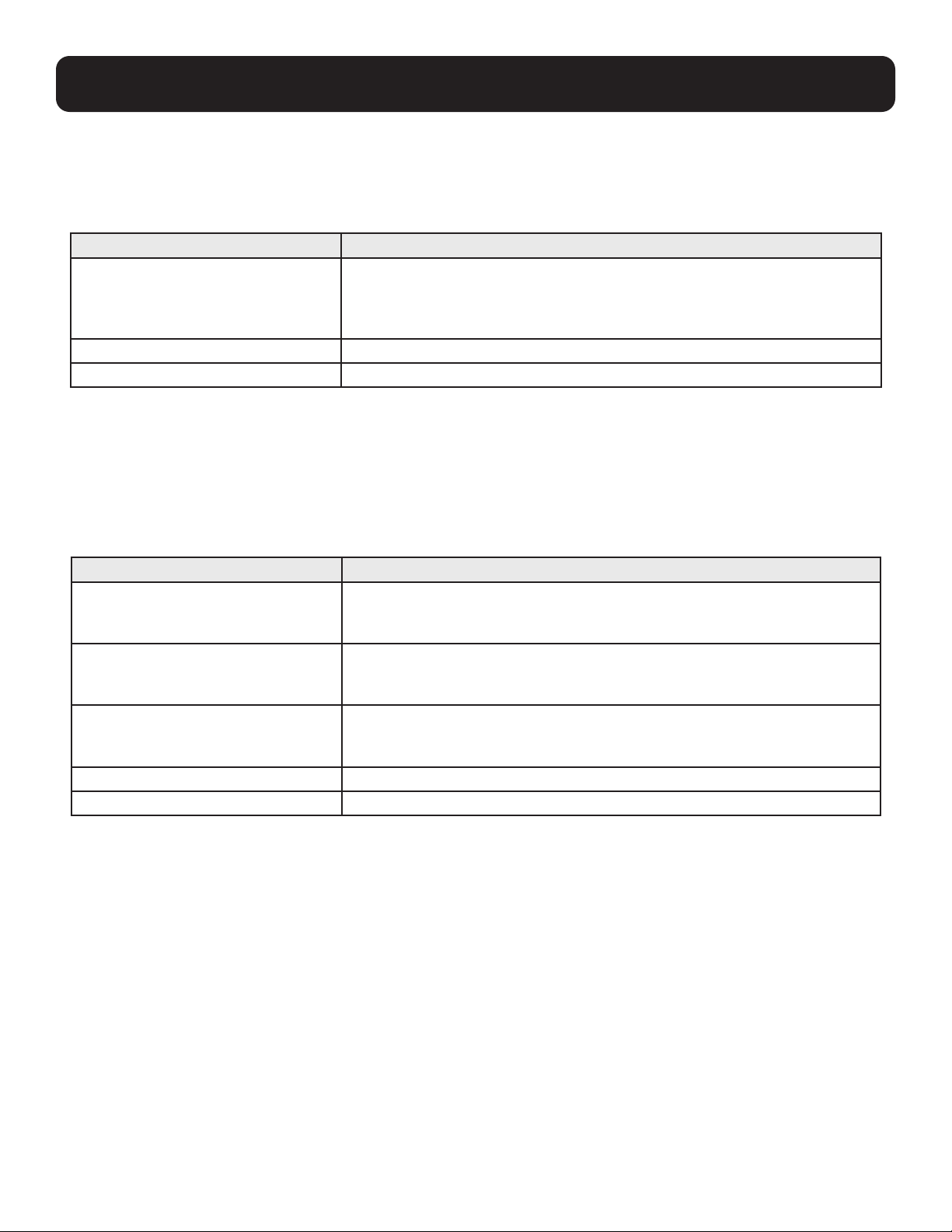
10.7 Account Settings
DVOE Manager contains two account levels: Administrator and User. The default passwords and privileges are detailed in
the table below:
Account Level Default Password Privileges
Administrator password All settings
User password Source assignment and B162-100-POE
receiver allocation on video wall layouts only
To change the default password, click the gear icon from the main screen and then click the Account tab.

42
11. CLI Commands
11.1 Overview
You can manage and configure the B162 devices using Telnet, TCP or RS-232 commands from a PC.
11.2 Before You Start
Make sure you have installed a PC to the Ethernet switch in your setup, as illustrated below:

43
11.3 Executing Commands
The following instructions presume command operations using a PC. To execute a command, do the following:
1. On a connected PC, open a command prompt as administrator.
2. Depending on the supported command type for your PC, do the following to connect to your deployment:
• Telnet connections - In the command prompt, type the IP address of any B162-100-POE receiver in your
setup and use port 23. For example:
• TCP connections - In the command prompt, type the IP address of any B162-100-POE receiver in your
setup and use port 9138. For example:
• RS-232 connections - In the DVOE Manager, set the IR/RS-232 of all B162-100-POE receivers to Manual
and select the Command Mode option.
3. When the connection is established, the message “Welcome to CLI mode” appears.
4. Type the command you wish to execute. For information on command syntax, see Commands.
5. Press Enter to execute the command.
6. When the command is successfully executed, the system returns a confirmation message.
7. To end the session, type logout in the command prompt and press Enter.
11. CLI Commands

44
11. CLI Commands
11.4 Commands
11.4.1 Guidelines
• The general form of a command is command name + parameter 1 + parameter 2 + control 1 + control 2.
• Always specify the command name first, followed by one or more parameters, and then the controls, if any.
• If you have two or more parameters, the order of these parameters among themselves does not affect the
result of the operation. For example, both of the following commands execute the same task:
o command name + parameter 1 + parameter 2
o command name + parameter 2 + parameter 1
• If you have two or more controls, the order of these controls among themselves does not affect the result of the operation.
For example, both of the following commands execute the same task:
o command name + control 1 + control 2
o command name + control 2 + control 1
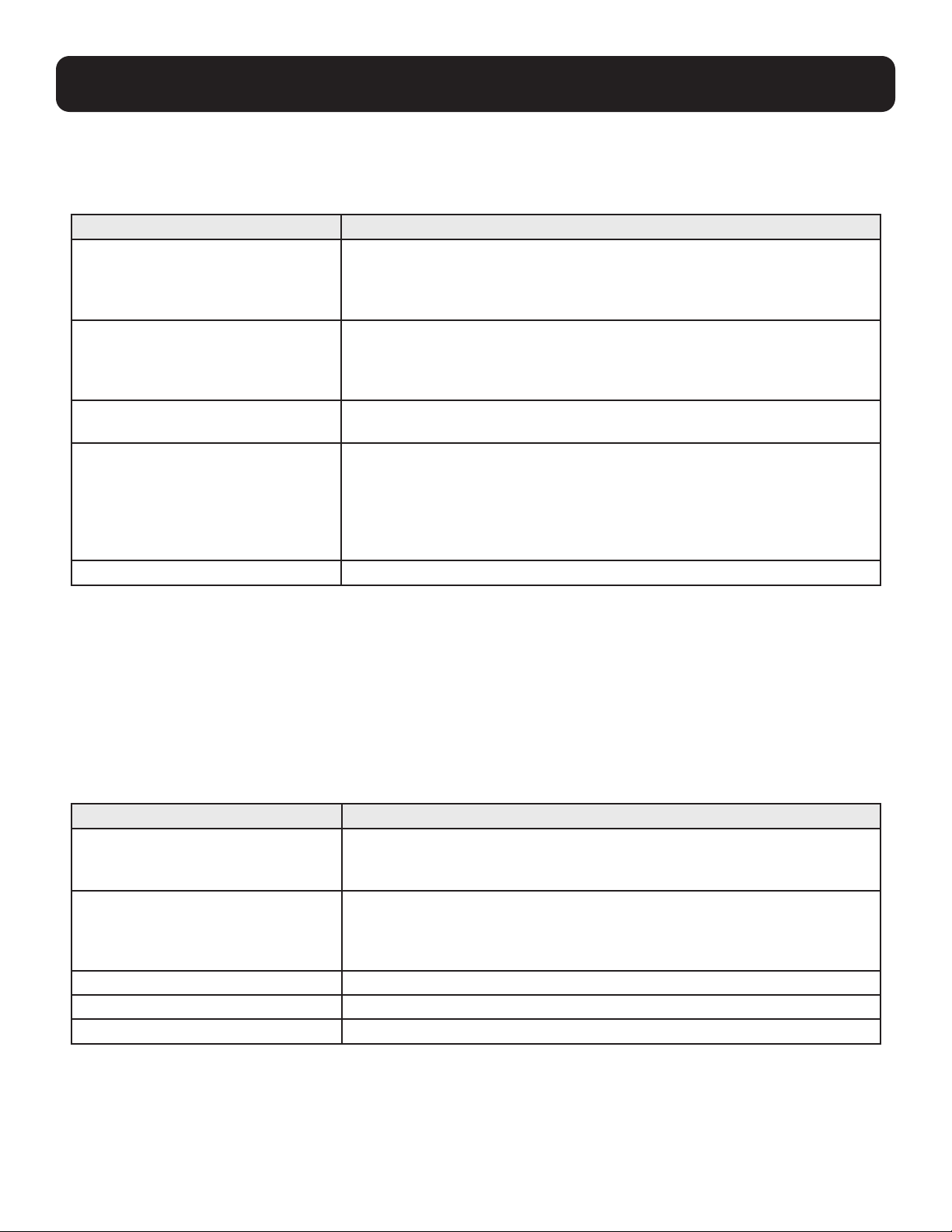
• The command syntax uses the following notations:
Notation Description
+ Indicates a space in the command.
[ ] Indicates optional items. Only type the information inside the brackets,
not the brackets themselves.
<argument> Indicates the name of the value the user must provide. Only type the
information within the angle brackets, not the brackets themselves.
| Indicates 2 or more mutually exclusive choices in a command line.
Only type one choice in the command line, not the symbol.
11.4.2 Switching Sources
To switch source on a display, type the command in this format: sw + i<port> + [o<port>] + on|off + \r\n
Control Description
i<port> Indicates the device ID, MAC address or IP address of the input device
(B162-001-POE).
o<port> Indicates the device ID, MAC address or IP address of the output device
(B162-100-POE). Omit this variable to assign the specified source to the
display you used to make the CLI connection.
on Enables the specified command.
off Disconnects from the current connection.
\r\n Ends the command.
Examples:
• To switch the source to a B162-001-POE transmitter with the IP address of 10.0.90.11 to the B162-100-POE receiver
you used to make the CLI connection, type sw i10.0.90.11 on
• To switch the source to a B162-001-POE transmitter with the ID of 1 on a B162-100-POE receiver with the ID of 5,
type sw i1 o5 on
• To stop source transmission from a B162-001-POE transmitter with the IP address of 10.0.70.43 to a B162-100-POE
receiver with the ID of 3, type sw i10.0.70.43 o3 off
45
11. CLI Commands
11.4.3 Switching Video, USB, RS-232 and/or IR Paths
Use this command to switch video, USB, RS-232 and/or IR transmission paths. To use this function, type the command
in this format: sw + i<port> + all | video | usb | serial | ir + o<port> + \r\n
Control Description
i<port> Indicates the device ID of the input device (B162-001-POE).
o<port> Indicates the device ID of the output device (B162-100-POE).
all Stands for all transmission paths, including video, USB and IR
of the specified transmitter.
video Stands for video path of the specified transmitter.
usb Stands for USB path of the specified transmitter.
serial Stands for RS-232 path of the specified transmitter.
ir Stands for IR path of the specified transmitter.
\r\n Ends the command.
Examples:
• To switch the video path of a B162-001-POE transmitter with the ID of 3 to a B162-100-POE receiver with an ID of 4,
type sw i3 video o4
• To switch the USB path of a B162-001-POE transmitter with the ID of 1 to a B162-100-POE receiver with an ID of 6,
type sw i1 usb o6
11.4.4 Disabling Video, USB, RS-232 and/or IR Paths
Use this command to disable video, USB, RS-232 and/or IR transmission paths for the specified B162-100-POE receiver. To use
this function, type the command in this format: sw + o<port> + all | video | usb | serial | ir + off + \R\N
Control Description
o<port> Indicates the device ID of the output device (B162-100-POE).
all Stands for all transmission paths, including video, USB and IR
of the specified receiver.
video Stands for video path of the specified receiver.
usb Stands for USB path of the specified receiver.
serial Stands for RS-232 path of the specified receiver.
ir Stands for IR path of the specified receiver.
\r\n Ends the command.
Example:
To disable the video, USB, RS-232, and IR paths for a B162-100-POE receiver with an ID of 4, type sw o4 all off
46
11. CLI Commands
11.4.5 Displaying Port-Switching Alerts
Use this command to display an alert message in the command line interface whenever a port is switched via the DVOE Manager,
the B162 device push buttons or the IR remote control. To enable or disable this function, type the command in this format:
echo + on | off + \R\N
Control Description
on Sends an alert in the command prompt window to inform port switching
configuration. For example, when the user assigns the B162-001-POE with
the device ID of 2 to the B162-100-POE with the device ID of 3, the system
sends this message in the command prompt window: sw o2 i3 on
off Disables the alert for port switching.
\r\n Ends the command.
11.4.6 Looking Up System Settings
You can look up the following system settings using the list command:
• Video Wall IDs
• Device ID, MAC address, IP address, firmware version and device name of B162 transmitters and receivers
To look up system settings, type the command in this format: list + rx | tx | device | videowall + \r\n
Control Description
rx Lists the system information of all B162-100-POE receivers in the environment,
including the device IDs, MAC addresses, IP addresses, firmware versions and
device names.
tx Lists the system information of all B162-001-POE transmitters in the
environment, including the device IDs, MAC addresses, IP addresses, firmware
versions and device names.
device Lists the system information of all B162 transmitters and receivers in the
environment, including the device IDs, MAC addresses, IP addresses, firmware
versions and device names.
videowall Lists the video wall settings.
\r\n Ends the command.
47
11. CLI Commands
11.4.7 Configuring Video Wall Settings
To apply a layout to a video wall and assign sources for display, type the command in this format:
vw + f<video_wall_ID> + l<layout_name> + [o<port>] + i<port> + on|off + /r/n
Control Description
<video_wall_ID> Indicates the ID of the video wall on which you wish to display the specified
layout and sources. You can also substitute this ID with the ID of any
B162-100-POE receiver used in the target video wall. To look up video wall IDs,
use the list command. For details, see Looking Up System Settings.
|<layout_name> Indicates the name of the layout that you wish to apply to the specified video
wall. To look up layout IDs, use the list command. For details, see Looking Up
System Settings. Omit this element when you want to use the same layout that
is applied to the target video wall.
i<port> Indicates the device ID, MAC address or IP address of the input device
(B162-001-POE) you wish to use.
o<port> Indicates the device ID, MAC address or IP address of the output device
(B162-100-POE) on which you wish to display the specified source (i<port>).
Note: If the specified layout contains 4 displays, 2 of which are merged, you
will need 3 pairs of o<port> + i<port> to indicate the source to be dis-
played on each display. Omit the o<port> element when specified layout does
not contain any merged screens.
\r\n Ends the command.
Example:
• To apply Layout 1 to a video wall with the ID of 8c8f12e62d3c87ef and assign the source connected to B162-001-POE
(device ID: 2) to the video wall, where one display is connected to B162-100-POE (IP address: 10.0.66.73), type the
following: vw + f8c8f12e62d3c87ef + lLayout 1 + o10.0.66.73 + i2 + on
11.4.8 Muting Receivers or Video Walls
To mute audio output on a B162-100-POE receiver or a video wall, type the command in this format:
mute + o<port> | f<video_wall_ID> + on|off + /r/n
Control Description
o<port> Indicates the device ID, MAC address or IP address of the output device
(B162-100-POE) you wish to mute. Use an asterisk (*) to mute all receivers in
the setup.
<video_wall_ID> Indicates the ID of the video wall you wish to mute. You can also substitute
this ID with the ID of any B162-100-POE receiver used in the target video wall.
To look up video wall IDs, use the list command. For details, see Looking Up
System Settings.
on Mutes the specified receivers or video walls.
off Unmutes the specified receivers or video walls.
\r\n Ends the command.
Example:
• To mute a receiver with the IP address 10.0.90.22, type mute o10.0.90.22 on
• To mute a video wall with the Video Wall ID 0, type mute f0 on
• To unmute a video wall with the Video Wall ID 1, type mute f1 off

48
11. CLI Commands
11.4.9 Disabling a Video Output
To disable video output from a specific receiver or on a particular video wall, type the command in this format:
blankscreen + o<port> | f<video_wall_ID> + on|off + \r\n
Control Description
o<port> Indicates the device ID, MAC address or IP address of the output device
(B162-100-POE) from which you wish to disable the video output. Use an
asterisk (*) to disable video output from all receivers in the setup.
<video_wall_ID> Indicates the ID of the video wall of which you wish to disable the video output.
You can also substitute this ID with the ID of any B162-100-POE receiver used
in the target video wall. To look up video wall IDs, see Looking Up System Set-
tings.
on Stops video output from the specified receivers or specified video wall.
off Allows video output from the specified receivers or specified video wall.
\r\n Ends the command.
Example:
• To disable video output on the receiver with the IP address of 10.0.90.22, type blankscreen o10.0.90.22 on
• To enable video output on the video wall with the Video Wall ID 0, type blankscreen f0 off
11.4.10 Enabling or Disabling a Receiver’s OSD Display
To enable or disable the OSD display of a specified receiver, type the command in this format:
osd + o<port> | f<video_wall_ID> + on|off + \r\n
Control Description
o<port> Indicates the device ID, MAC address or IP address of the output device (B162-
100-POE) for which you wish to display the OSD.
<video_wall_ID> Indicates the ID of the video wall for which you wish to display the OSDs. You
can also substitute this ID with the ID of any B162-100-POE receiver used in
the video wall. To look up video wall IDs, see Looking Up System Settings.
on Displays the OSD of the specified receiver.
off Hides the OSD of the specified receiver.
\r\n Ends the command.
Example:
• To display the OSD of a B162-100-POE receiver with the IP address 10.0.90.22, type osd o10.0.90.22 on
• To hide the OSDs of the B162-100-POE receivers for a video wall with the Video Wall ID 0, type osd f0 off

49
11. CLI Commands
11.4.11 Configuring EDID Mode
To set the EDID mode of a specified B162-001-POE transmitter, type the command in this format:
edid + i<port> + <EDID_mode> + \r\n
Control Description
i<port> Indicates the device ID, MAC address or IP address of the transmitter
(B162-001-POE) connected to the source of the target display.
<EDID_mode> Indicates the EDID mode you wish to set to the specified transmitter. Valid
inputs include:
• Default – Sets up the input to an optimum configuration based on EDID
predefined by Tripp Lite.
• Auto – Sets up the input to the highest resolution of the connected displays.
• Manual – Sets up the input to user’s configuration.
• Remix –
Sets up the input to an optimum resolution of the connected displays.
\r\n Ends the command.
Example:
• To set the EDID mode of a transmitter with the device ID of 16 to auto, type edid i016 auto
11.4.12 Rebooting the B162 Units
To reboot a B162 transmitter or receiver, type the command in this format: reset + a<port> | i<port> |o<port> + \r\n
Control Description
a<port> Indicates the device ID or IP address of the target transmitter or receiver.
i<port> Indicates the device ID of the target input device (B162-001-POE).
Use an asterisk (*) to target all transmitters in the environment.
o<port> Indicates the device ID of the target output device (B162-100-POE).
Use an asterisk (*) to target all receivers in the environment.
\r\n Ends the command.
Example:
• To reboot the transmitter with the IP address of 10.0.60.13, type reset i10.0.60.13 or reset a10.0.60.13
• To reboot all receivers, type reset o*

50
11. CLI Commands
11.4.13 Setting the Baud Rate
To set the baud rate of RS-232 serial transmission for B162 devices, type the command in this format:
baud + a<port> | i<port> |o<port> + <baud_rate> + \r\n
Control Description
a<port> Indicates the MAC address or IP address of the target transmitter or receiver. Use
an asterisk (*) to target all transmitters and receivers in the environment.
i<port> Indicates the device ID of the target input device (B162-001-POE). Use an aster-
isk (*) to target all transmitters in the environment.
o<port> Indicates the device ID of the target output device (B162-100-POE). Use an
asterisk (*) to target all receivers in the environment.
<baud_rate>
Indicates the baud rate to which you wish to set the target devices. Valid inputs
include 9600, 19200, 38400 and 115200.
\r\n Ends the command.
Example:
• To set the baud rate of a transmitter with the device ID of 3 to 115200, type baud a3 115200
• To set all receivers to default, type baud o* 9600
11.4.14 Displaying Device Status
You can display the status of B162 transmitters or receivers or the connection status of B162-001-POE transmitters to
B162-100-POE receivers. To do this, type the command in this format: read + [i<port>] | [o<port>] + \r\n
Control Description
i<port> Indicates the device ID, MAC address or IP address of the target input
device (B162-001-POE). Use an asterisk (*) to target all transmitters in the
environment.
o<port> Indicates the device ID, MAC address or IP address of the target output
device (B162-100-POE). Use an asterisk (*) to target all receivers in the
environment.
\r\n Ends the command.
Example:
• To look up the device status of all transmitters, type read i*
• To look up the device status of a receiver with the IP address of 10.0.80.66, type read o10.0.80.66
• To look up the connection status of transmitters to receivers in the environment, type read

51
12. Important Safety Instructions
12.1 General Safety Instructions
• This product is for indoor use only.
• Read all of these instructions. Save them for future reference.
• Follow all warnings and instructions marked on the device.
• Do not place the device on any unstable surface (cart, stand, table, etc.). If the device falls, serious damage will result.
• Do not use the device near water.
• Do not place the device near, or over, radiators or heat registers.
• The device cabinet is provided with slots and openings to allow for adequate ventilation. To ensure reliable operation, and to
protect against overheating, these openings must never be blocked or covered.
• The device should never be placed on a soft surface (bed, sofa, rug, etc.) as this will block its ventilation openings. Likewise, the
device should not be placed in a built-in enclosure unless adequate ventilation has been provided.
• Never spill liquid of any kind on the device.
• Unplug the device from the wall outlet before cleaning. Do not use liquid or aerosol cleaners. Use a damp cloth for cleaning.
• The device should be operated from the type of power source indicated on the marking label. If you are not sure of the type of
power available, consult your dealer or local power company.
• To prevent damage to your installation it is important that all devices are properly grounded.
• Do not allow anything to rest on the power cord or cables. Route the power cord and cables so that they cannot be stepped on or
tripped over.
• Position system cables and power cables carefully. Be sure nothing rests on any cables.
• Never push objects of any kind into or through cabinet slots. They may touch dangerous voltage points or short out parts resulting
in a risk of fire or electrical shock.
• Do not attempt to service the device yourself. Refer all servicing to qualified service personnel.
• If the following conditions occur, unplug the device from the wall outlet and bring it to qualified service personnel for repair.
o The power cord or plug has become damaged or frayed.
o Liquid has been spilled into the device.
o The device has been exposed to rain or water.
o The device has been dropped, or the cabinet has been damaged.
o The device exhibits a distinct change in performance, indicating a need for service.
o The device does not operate normally when the operating instructions are followed.
• Only adjust those controls that are covered in the operating instructions.
• Improper adjustment of other controls may result in damage that will require extensive work by a qualified technician to repair.
12.2 Rack-Mounting Safety Instructions
• Before working on the rack, make sure that the stabilizers are secured to the rack, extended to the floor, and that the full weight of the rack
rests on the floor. Install front and side stabilizers on a single rack or front stabilizers for joined multiple racks before working on the rack.
• Always load the rack from the bottom up, and load the heaviest item in the rack first.
• Make sure that the rack is level and stable before extending a device from the rack.
• Use caution when pressing the device rail release latches and sliding a device into or out of a rack; the slide rails can pinch your fingers.
• After a device is inserted into the rack, carefully extend the rail into a locking position, and then slide the device into the rack.
• Do not overload the AC supply branch circuit that provides power to the rack. The total rack load should not exceed 80 percent of the
branch circuit rating.
• Make sure that all equipment used on the rack – including power strips and other electrical connectors – is properly grounded.
• Ensure that proper airflow is provided to devices in the rack.
• Ensure that the operating ambient temperature of the rack environment does not exceed the maximum ambient temperature specified for
the equipment by the manufacturer.
• Do not step on or stand on any device when servicing other devices in a rack.

52
13. Specifications
Function B162-100-POE (Output) B162-001-POE (Input)
Video Output/Input
Interfaces (1x) HDMI (Female)
Impedance 100 Ω
Maximum Distance 3 m
Video
Maximum Data Rate Avg: 150 ~ 500 Mbps
Compliance HDMI (4K), HDCP
Max. Resolutions/Distances 4096 x 2160 (@ 30 Hz) with 4:4:4 @
100 m (Cat5e/6, point to point)
4096 x 2160 (@ 30 Hz) with 4:4:4 or
4096 x 2160 (@ 60 Hz) with 4:2:0 @
100 m (Cat5e/6, point to point)
Audio
Output/Input (1x) HDMI (Female)
(1x) 3.5 mm Mini Stereo (Female)
Connectors
Unit to Unit (2x) RJ45 (Female) (1x) RJ45 (Female)
Power (1x) DC Power Jack with locking
(1x) RJ45 (PoE)
Control
IR (1x) 3.5 mm Mini Stereo (Female)
RS-232 Connector Terminal Block, (3x) Pole
RS-232 Baud Rate 19200
RS-232 Data Bits 8
RS-232 Stop Bits 1, no parity and flow control
USB (2x) USB-A (Female) (1x) USB-B (Female)
Push Buttons
ID Number Selection (3x) Push Buttons (2x) Push Buttons
Power
Power Consumption DC5V:5.22W:46BTU
DC48V:6.52W:52BTU
DC5V:3.49W:16BTU
DC48V:4.36W:20BTU
Environmental
Operating Temperature 32° to 104°F (0° to 40°C)
Storage Temperature -4° to 140°F (-20° to 60°C)
Humidity 0 to 80% RH, Non-Condensing
53
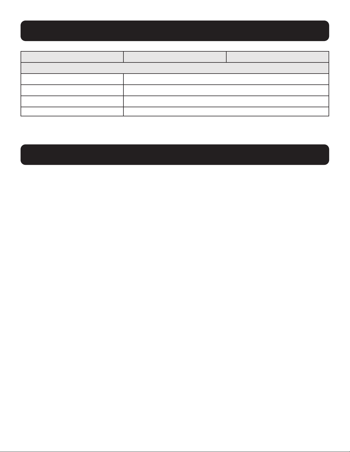
13. Specifications
Function B162-100-POE (Output) B162-001-POE (Input)
Physical Properties
Housing Metal
Weight 1.5 lb. (0.68 kg)
Size (L x W x H) w/Bracket 6.7 x 5.78 x 1.18 in. (17.02 x 14.69 x 3 cm)
Size (L x W x H) w/o Bracket 6.54 x 4.92 x 1.14 in. (16.6 x 12.49 x 2.9 cm)
Note: Supports 1920 x 1200 @ 60 Hz reduced blanking (Default EDID only).
• Google Chrome: 60.0.3112 or later
• Mozilla Firefox: 54.0.1 or later
• Opera: 46 or later
14. Supported Browsers

54
15. Warranty and Product Registration
1-Year Limited Warranty
TRIPP LITE warrants its products to be free from defects in materials and workmanship for a period of one (1) year from the date of initial
purchase. TRIPP LITE’s obligation under this warranty is limited to repairing or replacing (at its sole option) any such defective products. To
obtain service under this warranty, you must obtain a Returned Material Authorization (RMA) number from TRIPP LITE or an authorized TRIPP
LITE service center. Products must be returned to TRIPP LITE or an authorized TRIPP LITE service center with transportation charges prepaid
and must be accompanied by a brief description of the problem encountered and proof of date and place of purchase. This warranty does
not apply to equipment which has been damaged by accident, negligence or misapplication or has been altered or modified in any way.
EXCEPT AS PROVIDED HEREIN, TRIPP LITE MAKES NO WARRANTIES, EXPRESS OR IMPLIED, INCLUDING WARRANTIES OF MERCHANTABILITY
AND FITNESS FOR A PARTICULAR PURPOSE. Some states do not permit limitation or exclusion of implied warranties; therefore, the aforesaid
limitation(s) or exclusion(s) may not apply to the purchaser.
EXCEPT AS PROVIDED ABOVE, IN NO EVENT WILL TRIPP LITE BE LIABLE FOR DIRECT, INDIRECT, SPECIAL, INCIDENTAL OR CONSEQUENTIAL
DAMAGES ARISING OUT OF THE USE OF THIS PRODUCT, EVEN IF ADVISED OF THE POSSIBILITY OF SUCH DAMAGE. Specifically, TRIPP LITE
is not liable for any costs, such as lost profits or revenue, loss of equipment, loss of use of equipment, loss of software, loss of data, costs
of substitutes, claims by third parties, or otherwise.
PRODUCT REGISTRATION
Visit tripplite.com/warranty today to register your new Tripp Lite product. You’ll be automatically entered into a drawing for a chance to win a
FREE Tripp Lite product!*
* No purchase necessary. Void where prohibited. Some restrictions apply. See website for details.
Regulatory Compliance Identification Numbers
For the purpose of regulatory compliance certifications and identification, your Tripp Lite product has been assigned a unique series
number. The series number can be found on the product nameplate label, along with all required approval markings and information. When
requesting compliance information for this product, always refer to the series number. The series number should not be confused with the
marketing name or model number of the product.
WEEE Compliance Information for Tripp Lite Customers and Recyclers (European Union)
Under the Waste Electrical and Electronic Equipment (WEEE) Directive and implementing regulations, when customers buy new
electrical
and electronic equipment from Tripp Lite they are entitled to:
• Send old equipment for recycling on a one-for-one, like-for-like basis (this varies depending on the country)
• Send the new equipment back for recycling when this ultimately becomes waste
Use of this equipment in life support applications where failure of this equipment can reasonably be expected to cause the failure of the life
support equipment or to significantly affect its safety or effectiveness is not recommended.
Tripp Lite has a policy of continuous improvement. Specifications are subject to change without notice. Photos and illustrations may differ
slightly from actual products.

55

56
1111 W. 35th Street, Chicago, IL 60609 USA • tripplite.com/support
21-03-154 • 93-3DE2_RevA
