Loading ...
F1 J
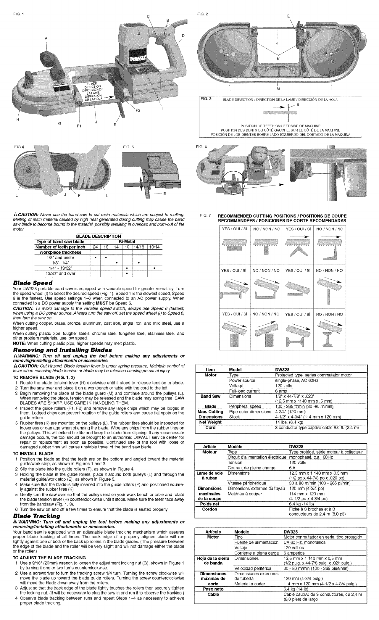
FIG 4 FIG. 5
_, CAUTION: Never use the band saw to cut resin materials which are subject to melting,
Melting ot resin material caused by high heat generated during cutting may cause the band
saw blade to become bound to the material, possibly resulting in overload and bum-out of #be
motor.
BLADE DESCRIPTION
Type of _d saw blade DiStal
Number of tee_ per inch 24 / 18 14 10 1i4/18 i0/14
Workplece _lckness /
1/8" and under • I •!
1/8"-1/4" •/•
t/4"- !3/32" *•
13/32" and over
',-'our DW328 portable band saw is equipped with variable speed for greater versatility. Turn
the speed wheel (I) to select the desired speed (Fig, I ), Speed 1 is the slowest speed; Speed
6 is the fastest, Use speed settings 1-6 when connected to an AC power supply. When
connected to a DO power supply the setting MUST be Speed 6.
CAUTION: To avoid damage to the variable speed s_cVtch,always use Speed 6 (fastest)
when using a DC power source. Always turn the saw off, set the speed wheel (I) to Speed 6,
then turn the saw eric
When cutting copper, brass, bronze, atuminum, cast Iron, angle iron, and mild steel, use a
higher speed,
When cutting plastic pipe, tougher steels, chro_ steel, tungsten steel stainless steel, and
other problem rnateriats, use low s_ed,
NOTE: When cutting piaatic pips, higher speeds may melt plaatic,
Removing and Installing Blades
_WARNING: Turn off and unplug the tool before making any adjustments or
removing/Tnstalling attachments or accessories,
_CAUTION; Cut Hazard. Blade tension lever is under spring pressure. Maintain control of
lever when releasing blade tension or blade may bo rdeased causing persof_a! injury.
TO REMOVE BLADE (FIG, t, 2)
1, Rotate the blade tension lever (H) clockwise until it stops to release tension in blade,
2. Turn the saw over and place it on a workbench or table with the cord to the left.
3, Begin removing the blade at the b_ade guard (M) and continue around the pulleys (L),
When removing the blade, tension may be released and the blade may spring free. SAW
BLADES ARE SHARP. USE CARE IN HANDLING THEM.
4. Inspect the guide rollers (Ff, F2) and remove any large chips which may be lodged in
them. Lodged chips can prevent rotation of the guide rollers and cause flat spots on the
guide rollers.
5. Rubber tires (K) are rreunted on the puileys (L). The rubber tires should be inspected for
looseness or damage when changing the blade, Wipe any chips from the rubber tires on
the pulleys. This will extend tire life and keep the btade from slipping. If any looseness or
damage occurs, the tool should be brought to an authorized D_:WALT service center for
repair or replace_nt as soon as poesible, Continued use of the tool w_h loose or
damaged rubber tires will cause unstable travel of the band saw blade.
TO INSTALL BLADE
1. Position the blade so that the teeth are on the bottom and angled toward the _terial
guide/work stop, as shown in Figures 1 and 3,
2, Slip the blade into the guide rollers (F), as shown in Figure 4,
3 Holding the blade in the guide rollers, place it around both pulleys (L) and through the
material guiddwork stop (E), as shown in Figure 5.
4, Make sure that the blade is fully inserted into the guide rollers (F) and positioned square-
ly against the rubber tires (K),
5, Gently turn the _w over so that the pulleys rest on your work bench or table and rotate
the blade tension lever (H) counterclockwise until it stops. Make sure the teeth face away
from the handsaw (Fig, 1,3),
6. Turn the saw on and off a few times to ensure that the blade is seated properly.
Blade Tracking
WARNING: Turn off and unplug the tool before making any adjustments or
removing/tnstalling attachments or accessories,
Your bend saw is equipped with an adiustable blade tracking mechanism which a.%ures
proper blade tracking at all times, The back edge of a properly aligned blade will run
lightiy against one or both of the back up rollers in the blade guides, (The pressure between
the edge of the blade and the roller will be very slight and wil! not damage either the blade
or the roller.)
TO ADJUST THE BLADE TRACKING
1 Use a 9/16" (20ram) wrench to loosen the adjustment locking nut (G), shown in Figure !
by turning it one or two turns counterclockwise.
ZUse a _rewdriver to turn the tracking screw !/4 turn, Turn{rig the screw clockwise will
move the blade up toward the blade guide rollers. Turning the _rew counterclockwise
will move the blade down away from the rollers,
3. Adjust so that the back edge of the blade lightly touches the rollers then securely tighten
the locking nut. tit will De ne_ssary to p_ug the saw in and run it to observe the tracking.)
4, Observe blade tracking between runs and repeat Steps 1-4 as necessaG, to achieve
proper blade tracking.
FIG, 7 RECOMMENDED CUTTING POSITIONS/POSmONS DE COUPE
RECOMMANDEES 1POSICIONES DE CORTE RECOMENDAD_
YES /OUI / SI NO /NON /NO YES /OUI /SJ NO /NON /NO
YES /OUi /S{ NO /NON /NO YES /OUI /S{ NO /NON /NO
YES /OUI /S[ NO/NON/NO YES fOUl / S{ NO/NON/NO
Item
Motor
Band Saw
Blade
Max. Cutting Pipe outer dimensions 4-3/4 ° (120 mm_
Dimensions Stock 4_1/2 _x 4-&/4" (114 mm x 120 mm)
Net Weight t4 Ibs. (6.4 kg)
Cord 3 conductor type captive cable 8,0 ft, (24 m)
Model DW328
.Type ...... Protected commutator motor
FuNoad current 6 amp
Dimensions 1/2° x 44W/8" x .020"
........................................................................................................._!,2:5rnrnx !_.@mmx:,5m_....................................
Peripheral speed 100 - 265 ft/min (30 =80 m/rain)
Article Mod_ DW328
Moteur Ty£e .................................................................................................................T)@e2_t_9 _
Circu_ d'alimentation _lectrique mon ophas_, ca,, 60Hz
Tension 120 volts
Oourant de #e!ne charge 6 A
Lame de scla Dimensions 12,5 mm x1 140 mm x 0,5 mm
r_ban ............................................................ o._._} __...._____.
Vbesse !_ripherique 30 & 80 m/rain (100 - 285 p_imin)
Dirr_en_ons Dimensions externes du tuyau 120 mm (4-3/4 pc)
maximales Mat@riau & seuper 114 mmx 120 mm
de la cou_ (4-1/2 pox 4-3/4 pc)
Poids net 6,4 kg (14 !b}
Cordon Fiche & 3broches et & 3
conducteurs de 2,4 m (8,0 pi))
A_°culo Modelo DW328
Motor TipQ Motor conm_ador en eerie, t!_o £_o .......
Fuente de atimentaci5n CA 60 Hz, mono_sica
Voltaje 120 ve_tios
Corriente a _tena carga 6 amperios
Hoja de la sierra Dimensiones t2,5 mm x1 140 mmx 0,5 mm
de ba_da ..................................................................(1o/22U)g, X_:7/8 pulg: X :_0 £#1#:).........................
Velocidad per_ferica 30 -80 m/min (100 -265 piedmin)
D|meneiones Dimensiones extefiores
_imas de ,de tube[[a ..................................................._29 :q_ _4:3_4 oPu!_:).........................................................................................
code Material a cortar 114 mm x 120 mm {4-1/2 x 4-3/4 pulg_)
Peso neto 6,4 kg (14 Ib}
Cable Cable cautivo de 3 conductores, de 2A m
(8,0 pies) de largo
Loading ...
Loading ...
Loading ...