
Owner's Manual
ICRRFTSMRN*I
23 HP
ELECTRIC START
48" MOWER
6 SPEED
GARDEN TRACTOR
Model No,
917.275010
• Safety
• Assembly
• Operation
• Maintenance
• Repair Parts
CAUTION:
Read and follow all Safety
Rules and Instructions before
operating this equipment.
For answers to your questions
about this product, Call:
1-800-659-5917
Sears Craftsman Help Line
5 am - 5 pro, Mon- Sat
SEARS, ROEBUCKAND CO., HOFFMAN ESTATES, ]L60179
VisitourCraftsmanwebsite:www.sears.com/craftsman
Warranty ............................................... 2
Safety Rules ......................................... 3
Product Specifications.......................... 6
Assembly .............................................. 9
Operation ............................................ 12
Maintenance Schedule ...................... 19
Maintenance ....................................... 18
Service and Adjustments.................... 22
Storage ............................................... 29
Troubleshooting ................................. 30
Repair Parts........................................ 34
Parts Ordedng ..................... Back Cover
LIMITED TWO YEAR WARRANTY ON CRAFTSMAN RIDING EQUIPMENT PARTS
For two (2) years from the date of purchase, if this Craftsman Riding Equipmentis
maintained, lubdcated and tuned up according to the instructionsin the owner's
manual, Sears will repair or replace, free of charge, any parts found to be defective in
matedal or workmanship. Warranty service is available free of charge by returning your
Craftsman dding equipment to your nearest Sears Service Center. In-home warranty
service is available but a tdp charge will apply. This warranty applies only while this
productisin the United States.
This Warranty does not sever:
• Expendable items which become worn dudng normal use, such as blades, spark
plugs, air cleaners, belts and oil filters.
• Tire replacement or repair caused by punctures from outsideobjects, such as nails,
thorns, stumps,or glass.
• Repairs necessary because of operator abuse, includingbut not limited to, damage
caused by towing objects beyond the capability of the dding equipment, impacting
objects that bend the frame or crankshaft, or over speeding the engine.
• Repairs necessary because of operator negligence, includingbut net limited to,
electdcal and mechanical damage caused by improper storage, failure to use the
proper grade and amount of engine oil, failure to keep the deck clear offlammable
debds, or the failure to maintain the equipment according to the instructionscon-
tained in the owner's manual.
• Engine (fuel system) cleaning or repairs caused by fuel determined to be contami-
nated or oxidized (stale). In general, fuel should be used withinthirty (30) days of its
purchase date.
• Riding equipment used for commercial or rental purposes. A productis =used for
commercial purpose" if is used for any purpose other than single family household
dwellingsor in usage where profit is made.
LIMITED 90 DAYWARRANTY ON BATTERY
For ninety (90) days from date of purchase, if any battery included with this dding
equipment proves defective in matedal or workmanship and our testing determines the
batterywill not hold a charge, Sears will replace the battery at no charge. Warranty
service is available free of charge by returning your Craftsman dding equipment to
your nearest Sears Service Center. In-home warranty service is available but a trip
charge will apply. This warranty applies only while this product is in the United States.
TO LOCATE THE NEAREST SEARS SERVICE CENTER OR TO SCHEDULE IN-HOME
WARRANTY SERVICE, SIMPLY CONTACT SEARS AT 1-800-4-MY-HOME
This Warranty gives you specificlegal dghts, and you may also have other dghts which
may vary from state to state.
Sears, Roebuck and Co., D/817 WA, Hoffman Estates, IL 60179
IMPORTANT:Thiscuttingmachineiscapableofamputatinghandsandfeetand
throwing,objects.Failuretoobservethefollowing safety instructionscoeld result in
sedous injury or death.
I. GENERAL OPERATION
• Read, understand, and follow all
instructionsin the manual and on the
machine before starting.
• Only allow responsible adults, who are
familiar with the instructions,to operate
the machine.
• Clear the area of objects such as
rocks,toys,wire, etc., whichcouldbe
picked up and thrown by the blade.
• Be sure the area isclear of other
people before mowing. Stop machine
if anyone enters the area.
• Never can'y passengers.
• Do not mow in reverse unless abso-
lutely necessary, Always look down
and behind before and while backing.
• Be aware of the mower discharge
directionand do not point itat anyone.
Do not operate the mower without
either the entire grass catcher or the
guard in plane.
• Slow down before turning.
• Never leave a running machine
unattended. Always turn off blades, set
parking brake, stop engine, and
remove keys before dismounting.
• Turn off blades when not mowing.
• Stop engine before removing grass
catcher or unclogging chute.
• Mow only in daylight or good artificial
light.
• Do not operate the machine while
under the influence of alcohol or drugs.
• Watch for traffic when operating near or
crossing roadways.
• Use extra care when loading or
unloading the machine into a trailer or
truck.
• Data indicates that operators, age 60
_/aearsand above, are involved in a
rge percentage of dding mower-
related injudes. These operators
should evaluate their ability to operate
the dding mower safely enough to
protectthemselves and others from
sedous in ury.
• Keep mach ne free of grass, leaves or
other debds build-up which can touch
hotexhaust / engine parts and bum. Do
notallow the mower deck to plow
leaves or other debds which can cause
build-upto occur. Clean any oil or fuel
spillage before operating or storing the
machine. Allow machine to cool before
storage.
II. SLOPE OPERATION
Slopes are a majorfactor related to loss-of-
control and tipover accidents, which can
result in severe in ury or death. All slopes
requ re extra caut on. f youcannot back up
the slope or if youfeel uneasy on it, do not
mow it.
DO:
• Mow up and down slopes, not across.
• Remove obstacles such as rocks,tree
limbs,etc.
• Watch for holes, ruts, or bumps.
Uneven terrain could overturn the
machine. Tall grass can hide ob-
stacles.
• Use slow speed. Choose a low gear
so that you will nothave to stop or shift
while on the slope.
• Follow the manufacturer's recommen-
dationsfor wheel weights or counter-
weights to improve stability.
• Use extra care with grass catchers or
other attachments. These can change
the stabilityof the machine.
• Keep all movement on the slopes slow
and gradual. Do not make sudden
changes in speed or direction.
• Avoid startingor stoppingon a slope. If
tires lose traction, disengage the
blades and proceed slowly straight
down the slope.
DO NOT:
• Do not tum on slopes unless neces-
sary, and then, turn slowly and gradu-
ally downhill, if possible.
• Do nat mow near drep-offs, ditches, or
embankments. The mower could
suddenly turnover if a wheel is over
the eddieof a cliff or ditch,or if an edge
caves In.
• Do not mow on wet grass. Reduced
traction could cause sliding.
• Do not try to stabilizethe machine by
putting your foot on the ground.
• Do not use grass catcher on steep
slopes.
III.CHILDREN
Tragicaccidentscanoccuriftheoperator
isnot alert tothe pmsanca ofchildren.
Children ere often attracted to the
machine and the mowing activity. Never
assume that children will remain where
you last saw them.
• Keep children out of the mowing area
and under the watchful care of another
responsible aduif.
• Be alert and turn machine off if children
enter the area.
• Before and when backing, look behind
and down for small children.
• Never carry children. They may fall off
and be sariously injured or interfere
with safe machine operation.
• Never allow children to operate the
machine.
• Use extra care when approaching blind
comers, shrubs, trees, or other objects
that may obscure vision.
IV. SERVICE
• Use extra care in handling gasoline
and other fuels. They are flammable
and vapors are explosive.
-Use only an approved container.
-Never remove gas cap or add fuel
with the engine running. Allow
engine to cool before refueling. Do
not smoke.
- Never refuel the machine indoors.
- Never store the machine or fuel
container inside where there is an
open flame, such as a water heater.
• Never run a machine inside a closed
area.
• Keep nuts and bolts, especially blade
attachment bolts, tightand keep
equipment in good condition.
• Never tamper with safety devices.
Check their proper operation regularly.
• Keep machine free of grass,leaves, or
other debds build-up. Clean oil or fuel
spillage. Allow machine to cool before
storing.
• Stop and inspect the equipment ifyou
strike an object. Repair, if necessary,
before restarting.
• Never make adjustments or repairs
with the engine running.
• Grass catcher components are subject
to wear, damage, and deterioration,
which could expose moving parts or
allow objects to be thrown. Frequently
check components and replace with
manufacturer's recommended pads,
when necessary.
• Mower blades are sharp and can cut.
Wrap the blade(s) or wear gloves, and
use extra caution when servicingthem.
• Check brake operationfrequently.
Adjust and service as required.
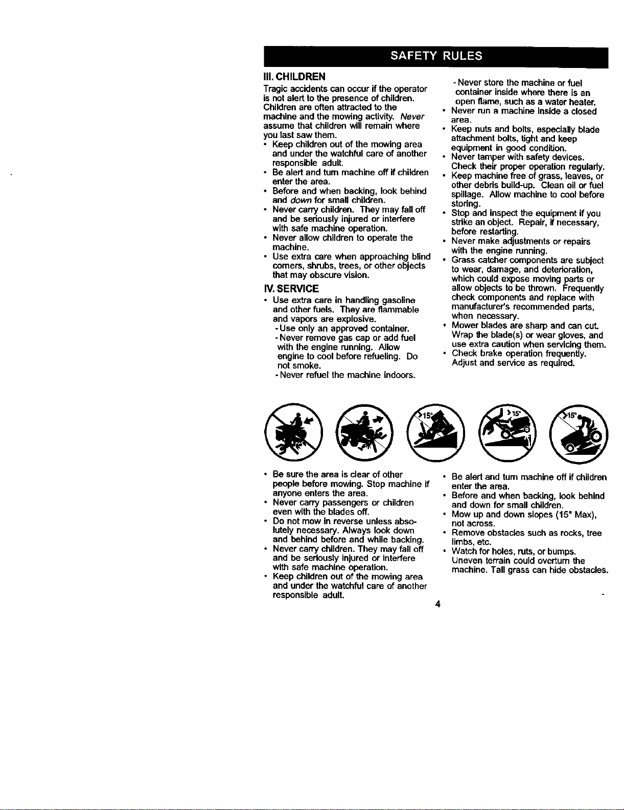
• Be sure the area isclear of other
people before mowing. Stop machine if
anyone enters the area.
• Never carry passengers or children
even with the blades off.
• Do notmow in reverse unless abso-
lutely necessary. Always lookdown
and behind before and while backing.
• Never carry children. They may fall off
and be seriously injured or interfere
with safe machine operation.
• Keep children out of the mowing area
and under the watchfulcare of another
responsible adult.
• Be alert and tum machine off if children
enter the area.
• Before and when backing, look behind
and down for small children.
• Mow up and down slopes (15 ° Max),
not across,
• Remove obstacles suchas rocks, tree
limbs,etc.
• Watch for holes, ruts,or bumps.
Uneven terrain could ovedum the
machine. Tall grass can hide obstacles.
4
• Use slow speed. Choose a low gear so
that you will nothave to stopor shift
while on the slope.
• Avoid starting or stoppingon a slope. If
tires lose traction, disengage the
blades and proceed slowly straight
down the slope.
• If machine stops while going uphill,
disengage blades, shift into reverse
and back down slowly.
• Do notturn on slopes unless neces-
sary, and then, turn slowly and gradu-
ally downhill, if possible.
_Look for this symbolto point out
important safety precautions. It means
CAUTIONI!t BECOMEALERT!ll YOUR
SAFETYIS INVOLVED.
CAUTION: In order to prevent
accidental starting when setting up,
transporting, adjusting or making repairs,
always disconnect spark plug wire and
place wire where it cannot contactspark
plug.
,_ CAUTION: Do not coast down a hill
in neutral,you may lose control of the
tractor.
_, CAUTION: Towonlythe attachments
that are recommended by and comply
with specificationsof the manufacturer of
your tractor. Use common sense when
towing. Operate only at the lowest
possiblespeed when on a slope. Too
heavy of a load, while on a slope, is
dangerous. Tires san lose tractionwith
the ground and cause you to lose control
ofyour tractor.
,_LWARNING: Engine exhaust, some of
its constituents, and certain vehicle
components contain or emit chemicals
known to the State of California tocause
cancer and birthdefects or other repro-
ductive harm.
_WARNING: Battery posts, terminals
and related accessories contain lead and
lead compounds, chemicals known to the
State of CaSfomia to cause cancer and
birthdefects or other reproductiveharm.
Wash hands after handling,
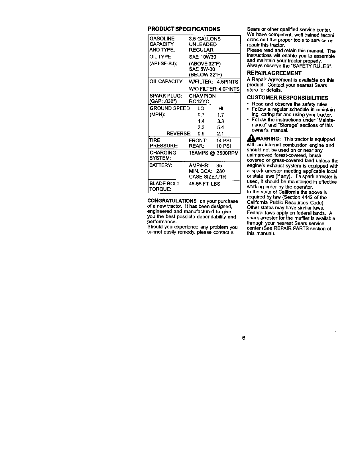
PRODUCTSPECIFICATIONS
GASOLINE 3.5GALLONS
CAPACITY UNLEADED
AND TYPE: REGULAR
OILTYPE SAE 10W30
API-SF-SJ): (ABOVE 32°F)
SAE 5W-30
(BELOW 32°F)
OILCAPACITY: W/FILTER: 4.5PINTS
W/O FILTER: 4.0PINTS
SPARK PLUG: CHAMPION
GAP: .030") RC12YC
GROUND SPEED LO: HI:
(MPH): 0.7 1.7
1.4 3.3
2.3 5.4
REVERSE: 0.9 2.1
TIRE FRONT: 14 PSI
PRESSURE: REAR: 10 PSI
CHARGING 15AMPS @ 3600RPM
SYSTEM:
BATTERY: AMP/HR: 35
MIN. CCA: 280
CASE SIZE:U1R
BLADE BOLT 45-55 FT. LBS
TORQUE:
CONGRATULATIONS on your purchase
of a new tractor. It has been designed,
engineered and manufactured to give
you the best possible dependability and
performance.
Should you expodenea any problem you
cannot easily remedy, please contact a
Sears or other qualifiedservice center.
We have competent, well-trained techni-
cians and the proper tools to service or
repair this tractor.
Please read and retain thismanual. The
instructionswill enable you to assemble
and maintain your tractor propody.
Always observe the =SAFETY RULES".
REPAIRAGREEMENT
A Repair Agreement is available on this
product. Contact your nearest Sears
storefor details.
CUSTOMER RESPONSIBILITIES
• Read and observe the safety rules.
• Follow a regular schedule in maintain-
ing, caring for and using your tractor.
• Follow the instructionsunder =Mainte-
nance"and =Storage" sections of this
owner's manual.
I_WARNING: This tractor is equipped
with an internal combustion engine and
should not be used on or near any
unimproved forest-covered, brush-
covered or grass-covered land unless the
engine's exhaust system is equipped with
a spark arrester meeting applicable local
or state laws(if any). If a spark attester is
used, it should be maintained in effective
workingorder by the operator.
In the state of California the above is
required by law (Section 4442 of the
California Public Resources Cede).
Other states may have similarlaws.
Federal laws apply on federal lands. A
spark arrester for the muffler is available
through your nearest Sears service
center (See REPAIR PARTS sectionof
this manual).
6
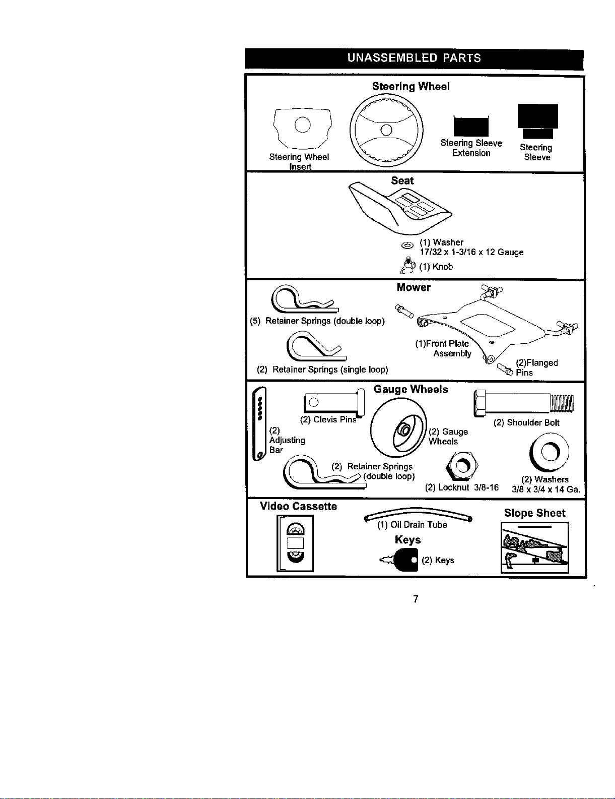
Steering Wheel
Insert
Steering Wheel
Steedng Sleeve Steering
Extension Sleeve
(1) Washer
17132 x %3/16 x 12 Gauge
_(1) Knob
(5) Retainer Spdngs (double loop)
(2) Retainer Spdngs (single loop)
ns
i_1 Gauge Wheels
._ !2da)_Ustin _ (W2)eGe_sUge-
/_ (2)Retainer Springs _(_'_
__double loop)
(2) Locknut 3/8-16
(2) Shoulder Bolt
(2) Washers
3/8 x 3/4 x 14 Ga.
Video Cassette _ Slope Sheet '
(1) UII uraln lUl3e
Keys
_ (2) Keys
Yournewtractorhasbeenassembled at the factory with exception of those parts k
unassembled for shipping purposes. To ensure safe and proper operation ofyour
tractor all parts and hardware you assemble must be tightened securely. Use the
correoftools as necessary to insure proper t_jhteess.
TOOLS REQUIRED FORASSEMBLY
A socket wrench set will make assembly
easier. Standard wrench sizes you need
are listed below.
(1) 9/t6"wrendn (1) Pliers
(1) 1/2"wrench (1) Utility knife
(1) 3N" socket with
ddve ratchet
(1) "fire pressure gauge
When rightor left hand is mentioned in
this manual, it means, from your point of
view,when you are in the operating
position (seated behind the steering
wheel).
TO REMOVE TRACTOR FROM
CARTON
UNPACK CARTON
1. Remove all accessible loose parts and
partscartons from carton.
2. Cut, fromtop to bottom, along lines on
all fourcorners of carton, and lay
panels fiat.
3. Remove mower and packing mated-
ais,
4. Check for any additionalloose parts or
cartons and remove.
BEFORE REMOVING TRACTOR
FROM SKID
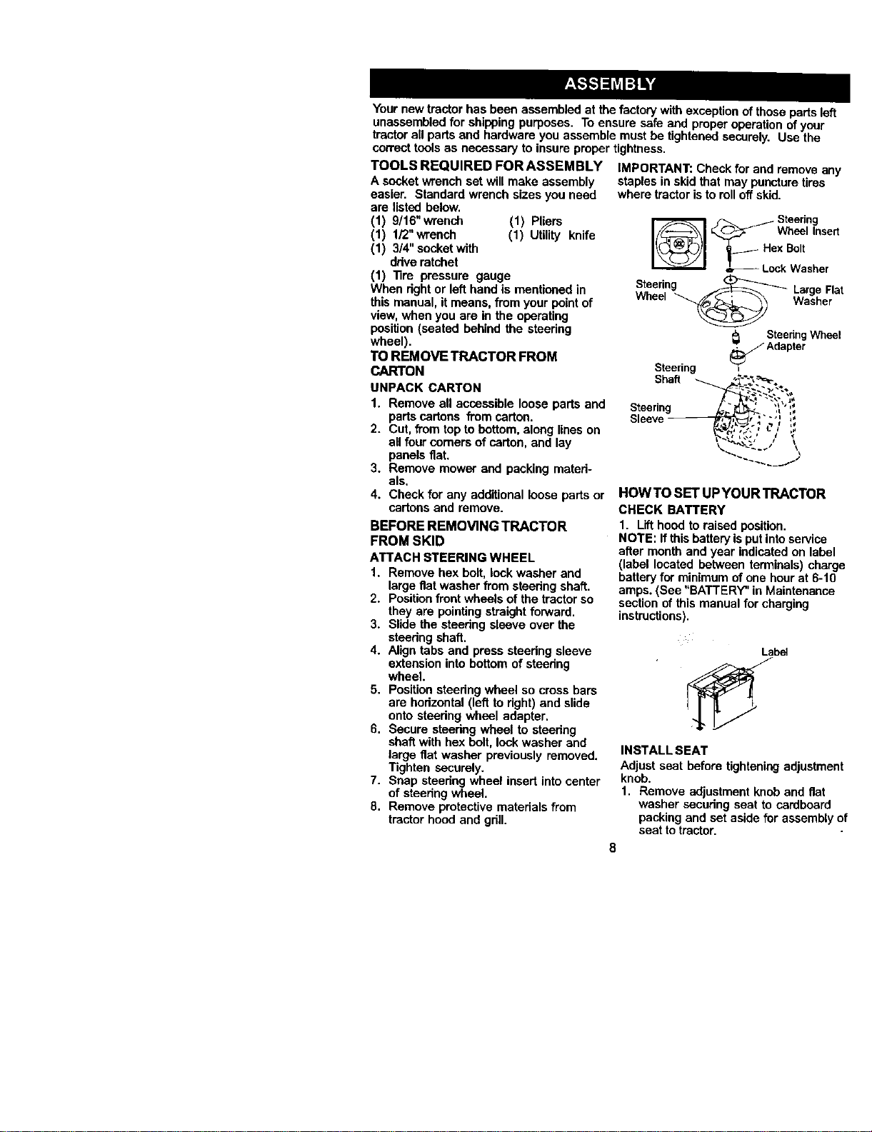
ATTACH STEERING WHEEL
1. Remove hex bolt, lock washer and
large flat washer from steedng shaft.
2. Positionfront wheels of the tractor so
they are pointingstraight forward.
3. Slide the steering sleeve over the
steedng shaft.
4. Align tabs and press steedng sleeve
extension into bottom of steering
wheel
5. Positionsteering wheel so cross bars
are horizontal (left to right) and slide
onto steedng wheel adapter,
6. Secure steedng wheel to steedng
shaft with hex bolt, lock washer and
large flat washer previously removed.
Tighten securely.
7. Snap steering wheel insert into center
of steering wheel.
8. Remove protective materials from
tractor hood and grill.
IMPORTANT: Check for and remove
staples in skid that may puncture tires
where tractor isto roll offskid.
Steering
_ _ Wheel In.,
_ LockWashe
Steering _ Large
Wheel _ Wash_
Steedng W|
Adapter
Steering
Shaft _ .,__"._,='_'-.
Steerin _k, ?_',I_
Sleeve .' _"_,'_
HOWTO SET UPYOUR TRACTOR
CHECK BATTERY
1. Lift hoed to raised position.
NOTE: If this batteryis putintoservic_
after monthand year indicated on lab
(label located between terminals) ch_
batteryfor minimum ofone hour at 6-'
amps. (See "BATTERY" in Maintenanc
section of this manual for charging
instructions).
Label
INSTALL SEAT
Adjust seat before tighteningedjustn
knob.
1. Remove adjustment knob and flat
washer sscudng seat to cardbean
packing and set aside for assembl
seat totractor.
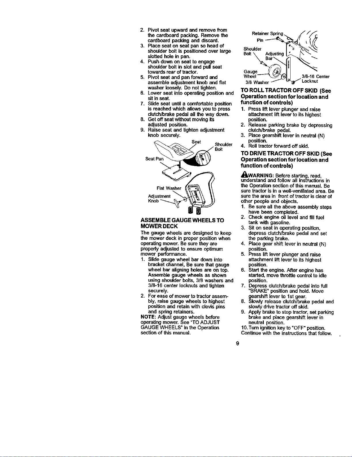
2. Pivotseatupwardand remove from
the cardboard packing. Remove the
cardboard packing and discard.
3. Place seat on seat pan so head of
shoulder bolt is positioned over large
slotted hole in pan.
4. Push down on seat to engage
shoulder bolt in slot and pull seat
towards rear of tractor.
5. Pivot seat and pan forward and
assemble adjustment knob and fiat
washer loosely. Do not tighten.
6. Lower seat into operating position and
sit in seat.
7. Slide seat untila comfortable position
is reached which allows you to press
clutch/brake pedal all the way down.
8. Get off seat without movingits
adjusted position.
9. Raise seat and tighten adjustment
knob securely.
Seat
Shoulder
Seat Par
ASSEMBLE GAUGE WHEELS TO
MOWER DECK
The gauge wheels are designed to keep
the mower deck in proper positionwhen
operatingmower. Be sure they are
propedy adjusted to ensure optimum
mower performance.
1. Slide gauge wheel bar down into
bracket channel, Be sure that gauge
wheel bar aligningholes are on top.
Assemble gauge wheels as shown
using shoulder bolts, 3/8 washers and
3/8-16 center Iocknutsand tighten
securely.
2. For ease of mower totractor assem-
bly, raise gauge wheels to highest
position and retain with clevis pins
and spdng retainers.
NOTE: Adjust gauge wheels before
operatingmower. See =TOADJUST
GAUGE WHEELS" in the Operation
sectionof this manual.
Retainer Sprin
Shoulder
Bolt\ Adjusting
Gauge _ __11 I
Wheel-- _J.J 3/8-16 Center
3/8 Washer_ _ Locknut
TO ROLL TRACTOR OFF SKID (See
Operation section for location and
function of controls)
1. Press liftlever plunger and raise
attachment lift leverto its highest
position.
2, Release parking brake by depressing
clutch/brake pedal.
3. Place gearshift lever in neutral (N)
position.
4. Rolltractorforward off skid.
TO DRIVE TRACTOR OFF SKID (See
Operation section for location and
function of controls)
_WARNING: Before starting, read,
understand and follow all ins_roctionsin
the Operation sectionof this manual. Be
sure tractor is in a well-ventilated area. Be
sure the area in front oftractor is clear of
other people and objects.
1. Be sure all the above assembly steps
have been completed.
2, Check engine oil level and fill fuel
tank with gasoline.
3, Sit on seat in operating position,
depress clutch/brake pedal and set
the parking brake.
4. Place gear shiftlever in neutral (N)
position.
5. Press lift lever plunger and raise
attachment lift lever to its highest
position.
6. Start the engine. After engine has
started, move throttle controlto idle
position.
7. Depress clutch/brake pedal intofull
"BRAKE" position and hold. Move
gearshiftlever to 1stgear.
8. Slowly release clutch/brake pedal and
slowlydrive tractoroff skid.
9. Apply brake tostop tractor, set parking
brake and place gearshift lever in
neutral position.
lO.Turo ignition key to "OFF" position.
Continue with the instructions that follow.
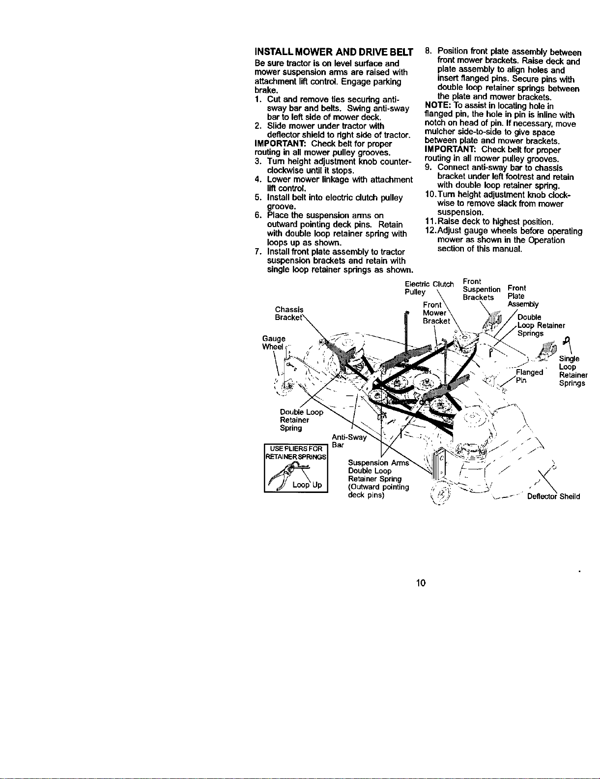
INSTALL MOWER AND DRIVE BELT
Be sure tractor is on level surface and
mower suspension arms are raised with
attachment liftcontrol Engage parking
brake.
1. Cut and remove ties securing anti-
sway bar and belts. Swing anti-sway
barto left side of mower deck.
2. Slide mower under tractor with
deflector shield to rightside of tractor.
IMPORTANT: Check belt for proper
routingin all mower pulley grooves.
3. Turn height adjustment knob counter-
clockwise until it stops•
4. Lower mower linkage with attachment
liftcontrol,
5. Install belt into electric clutch pulley
groove.
6. Place the suspension arms on
outward pointingdeck pins. Retain
with double loop retainer spring with
loops up as shown.
7. Installfront plate assembly to tractor
suspension brackets and retain with
single loop retainer springs as shown.
Chassis
Gauge
Retainer
Spring
USE PLIERS FOR
RETAINER SPRINGS
Anti-Sway
Bar
Suspension
Double Loop
Retainer Spring
(Outward pointing
deck pins)
8. PositionfTontplate assembly between
front mower brackets. Raise deck and
plate assembly toalign holes and
insert flanged pins. Secure pins with
double loop retainer springs between
the plate and mower brackets.
NOTE: To assistin locatingholein
flanged pin, the hole in pin is inline with
notchon head of pin. If necessary,move
mulcher side-to-side to give space
between plate and mower brackets.
IMPORTANT: Check belt for proper
routingin all mower pulley grooves.
9. Connect anti-sway bar to chassis
bracket under left footrestand retain
with double loop retainer spring.
10.Tum height adjustmentknob clock-
wise to remove slackfrom mower
suspension.
11. Raise deck to highest position.
12.Adjust gauge wheels before operating
mower as shown in the Operation
section of this manual.
Electric Clutch Front
Pulley Suspention Front
Brackets Plate
Assembly
,LoopRetainer
Springs
/_ .._" Single
.... Loop
, Flanged Retainer
_ !" _Pin Springs
: . _\ / ,
10
CHECK TIRE PRESSURE
The tires on your tractor were ovednflated
at the factory forshipping purposes.
Correcttire pressure is imp_tant for host
cutting performance.
• Reduce tire pressure to PSI shown in
_PRODUCT SPECIFICATIONS" section
of this manual.
CHECK DECK LEVELNESS
For host cuttingresults, mower housing
should be propedy leveled. See =TO
LEVEL MOWER HOUSING" in the
Service and Adjustments section of this
manual.
CHECK FOR PROPER POSITION OF
ALL BELTS
See the figuresthat are shown for
replacing motion and mower blade ddve
belts in the Service and Adjustments
section ofthis manuel. Vedfythat the
belts are routed correctly.
CHECK BRAKE SYSTEM
After you leam how to operate your
tractor,check tosee that the brake is
propedy adjusted. See "TO ADJUST
BRAKE" in the Service and Adjustments
section of this manual.
V"CHECKLIST
Before you operate and enjoy your new
tractor,we wish to assure that you receive
the host performance and satisfaction
from thisQuality Product.
Please review the following checklist:
,/All assembly instructionshave been
completed.
,/No remaining loose parts in carton.
,/Battery is propedy prepared and
charged. (Minimum 1 hour at 6 amps).
,/Seat is adjusted comfortablyand
tightened securely.
vAIl tires are properlyinflated. (For
shipping purposes, the tireswere
ovednflated at the factory).
v"Be sure mower deck is propedy leveled
side-to-side/front-to-rear for best cutting
results. (Tires must be propedyinflated
for leveling).
,/Check mower and ddve belts. Be sure
they are routed propedy around pulleys
and inside all belt keepers.
,/Check widng. See that all connections
are stillsecure and wires are prepedy
clamped.
While leaming how to use your tractor,
pay extra attention to the following
important items:
,/Engine oil is at proper level.
,/Fuel tank isfilled with fresh, clean,
regular unleaded gasoline.
,,/Become familiar with all controls- their
location and function. Operate them
before you startthe engine.
,/Be sure brake system is in safe
operating condition.
11
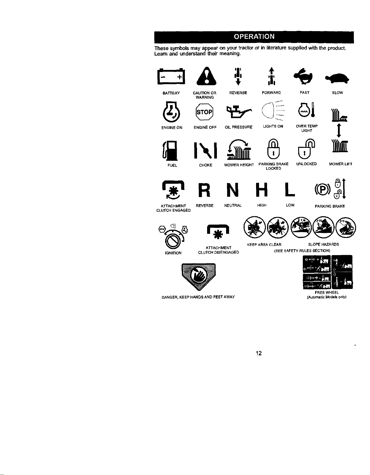
These symbols may appear on your tractor or in literaturesupplied with the product.
Learn and understand their meaning.
BA'rFERY CAUTION OR REVERSE FORWARD FAST SLOW
WARNING
ENGINE ON ENGINE OFF OIL PRESSURE LIGHTS ON OVER "FEMP t
LIGHT
1
M
FUEL CHOKE MOWER HEIGHT PARKING BRAKE UNLOCKED
LOCKED
MOWER LIFT
r_'_ R N H L
ATTACHMENT REVERSE NEUTRAL HIGH LOW PARKING BRAKE
CLUTCH ENGAGED
KEEP AREA CLEAR SLOPE HAZARDS
ATTACHMENT
IGNITION CLUTCH DISENGAGED (SEE SAFETY RULES SECTION)
DANGER, KEEP HANDS AND FEET AWAY
FREE WHEEL
(Automatic Models only)
12
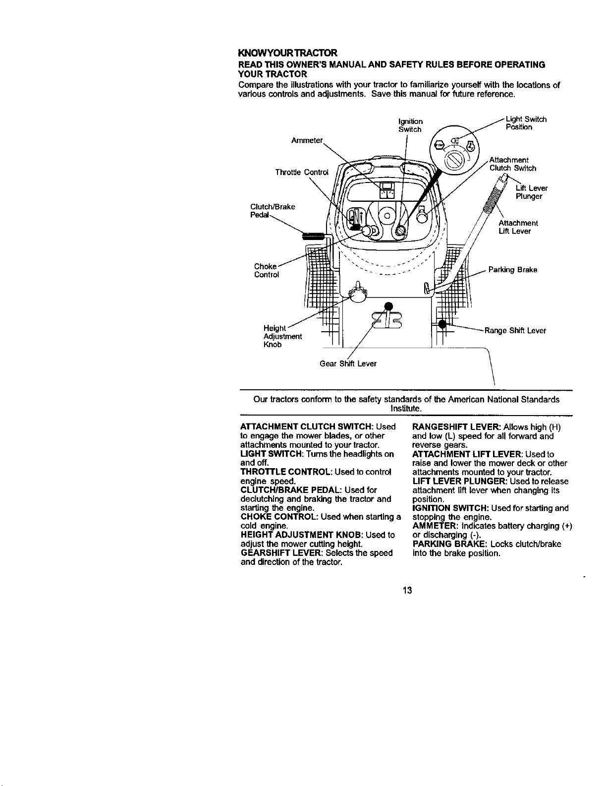
KNOWYOURTRACTOR
READ THIS OWNER'S MANUAL AND SAFETY RULES BEFORE OPERATING
YOUR TRACTOR
Compare the illustrationswith your tractor to familiarize yourself with the locations of
various controlsand adjustments. Save this manual for future reference.
IgnitJon
Switch Pc_s_tion
Ammeter
Attachment
ThrottJe Contro4 Switch
Clutch/Brake
Plunger
Attachment
Lift Lever
Contml
Brake
Height
Adjustment
Knob
e Shift Lever
Gear Shift Lever
Our tractorsconform to the safety standards of the American NationalStandards
Institute.
ATTACHMENT CLUTCH SWITCH: Used
to engage the mower blades, or other
attachments mountedto your tractor.
LIGHT SW]TCH: Turns the headlightson
and off.
THROTTLE CONTROL: Used tocontrol
engine speed.
CLUTCHIBRAKE PEDAL: Used for
declutchingand braking the tractor and
starting the engine.
CHOKE CONTROL: Used when startinga
cold engine.
HEIGHT ADJUSTMENT KNOB: Used to
adjustthe mower cuttingheight.
GEARSHIFT LEVER: Selects the speed
and directionofthe tractor.
RANGESHIFT LEVER: Allows high (H)
and low (L) speed for all forward and
reverse gears.
ATTACHMENT LIFT LEVER: Usedto
raise and lower the mower deck or other
attachments mounted to your tractor.
LIFT LEVER PLUNGER: Used to release
attachment lift[ever when changing its
position.
IGNITION SWITCH: Usedfor starting and
stopping the engine.
AMMETER: Indicates battery charging (+)
or discharging (-).
PARKING BRAKE: Locks clutch/brake
into the brake position.
13
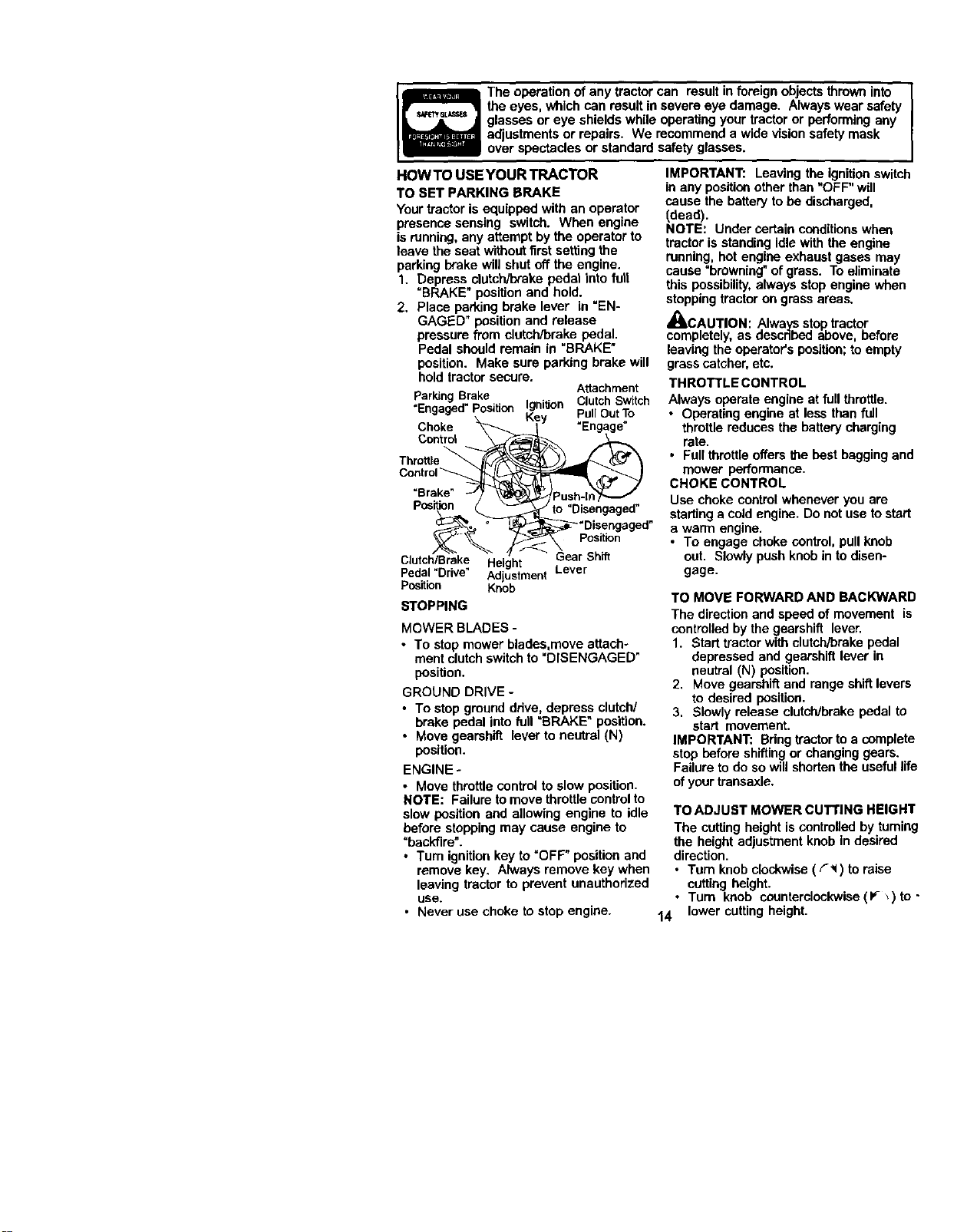
The operation of any tractor can resultin foreign objects thrown into
the eyes, which can result in severe eye damage. Always wear safety
glasses or eye shields while operatingyour tractor or performing any
adjustments or repairs. We recommend a wide vision safety mask
over spectacles or standard safety glasses.
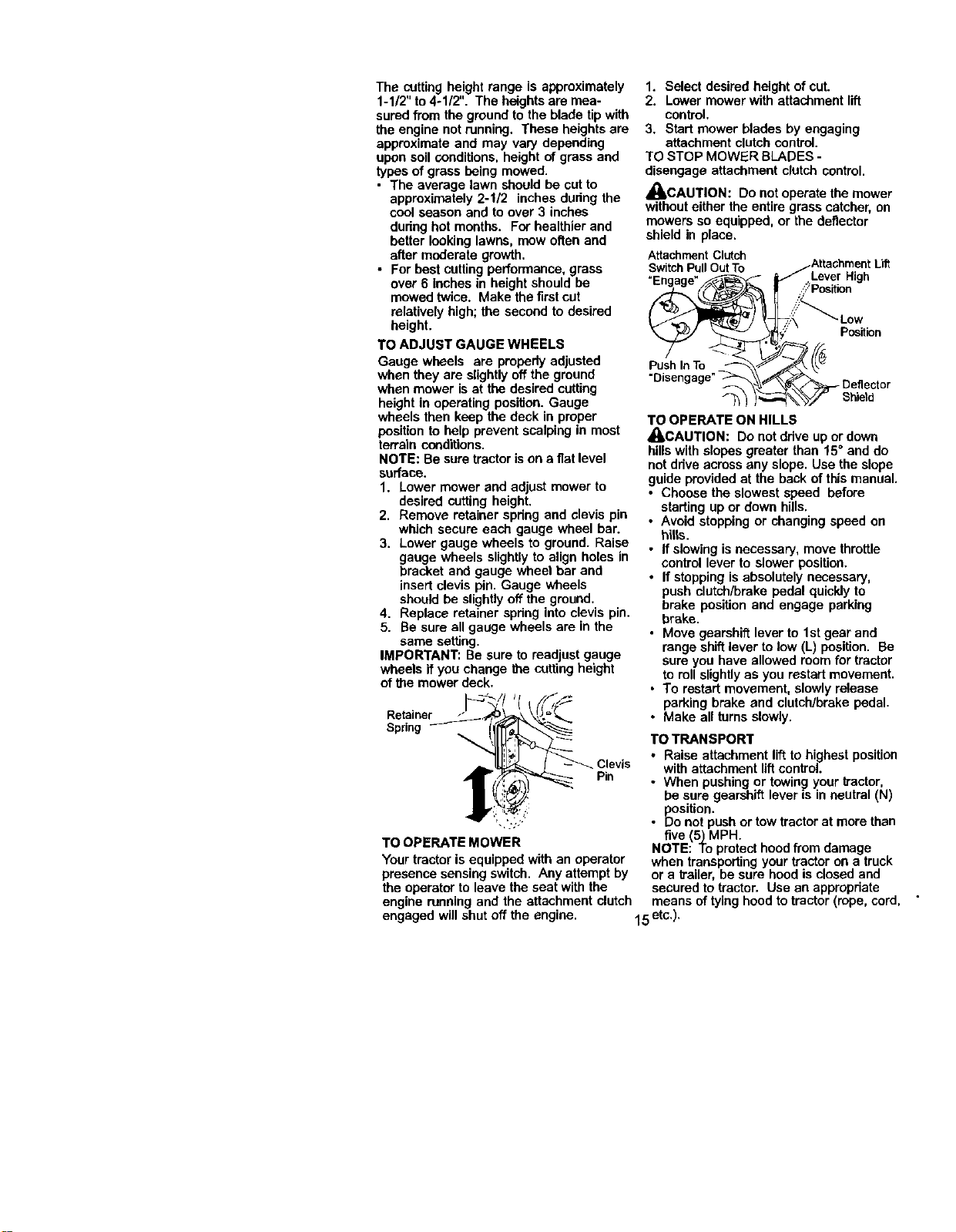
HOW TO USE YOUR TRACTOR
TO SET PARKING BRAKE
Your tractor is equipped with an operator
presence sensing switch. When engine
is running,any attempt by the operator to
leave the seat withoutfirst setting the
parking brake will shut off the engine.
1. Depress clutch/brake pedal into fur!
"BRAKE" position and hold.
2. Place parking brake lever in "EN-
GAGED" position and release
pressure from clutch/brake pedal.
Pedal should remain in "BRAKE"
position. Make sure parking brake will
hold tractorsecure.
Attachment
ParkingBrake
. . . =,.=,i_._n Clutch Switch
Engaged Position ,_.... - ....
•, Key P'UII uut 1(3
Choke _'_ _ I" "Engage"
Control
Thr°ttl _ke.__-_
Control _
=Bra
Posit_._ _ J_ "Disengaged"
_,._ ° _'Disengaged"
"- position
Clutch/Brake Height
Pedal "Drive" Adjustment Lever
Position Knob
STOPPING
MOWER BLADES -
• To stop mower blades,move attach-
ment clutch switch to "DISENGAGED"
position.
GROUND DRIVE -
• To stop ground ddve, depress clutch/
brake pedal into full "BRAKE" position.
• Move gearshift lever to neutral (N)
position.
ENGINE-
• Move throttle control to slow position.
NOTE: Failure tomove throttle control to
slow position and allowing engine to idle
before stoppingmay cause engine to
"backfire".
• Turn ignition key to "OFF" position and
remove key. Always remove key when
leaving tractor to prevent unauthorized
use.
• Never use choke to atop engine.
IMPORTANT: Leaving the ignitionswitch
in any positionother than "OFF" will
cause the battery to be discharged.
(dead).
NOTE: Under certain conditionswhen
tractor is standing idlewith the engine
running, hotengine exhaust gases may
cause "browning"ofgrass. Toeliminate
this possibility,always stop engine when
stopping tractor on grass areas.
_CAUTION: .Alwaysstop tractor
completely,as eescnbed above, nefore
leaving the operator's position;to empty
grass catcher,etc.
THROTTLE CONTROL
Always operate engine at full throttle.
• Operating engine at less than full
throttle reduces the batterycharging
rate.
• Full throttleoffers the best bagging and
mower performance.
CHOKE CONTROL
Use choke control whenever you are
startinga cold engine. Do notuse tostart
a warm engine.
• To engage choke control, pull knob
out. Slowly push knobin to disen-
gage.
TO MOVE FORWARD AND BACKWARD
The directionand speed of movement is
controlledbythe gearshift lever.
1. Start tractor with clutch/brake pedal
depressed and gearshift lever in
neutral (N) position.
2. Move gearshift and range shiftlevers
to desired position.
3. Slowly release clutcWbrakepedal to
start movement.
IMPORTANT: Bdng tractor to a complete
stop before shifting or changing gears.
Failure to do so will shorten the useful life
of your transaxle.
TO ADJUST MOWER CUTTING HEIGHT
The cuttingheight is controlledby turning
the height adjustment knob in desired
direction.
• Turn knob clockwise( F,_) toraise
cutting height.
• Turn knob counterclockwise(P- _) to -
14 lower cutting height.
Thecuttingheightrangeisapproximately
1-1/2"to4-1/2".Theheightsaremea-
suredfromthegroundtothebladetipwith
theengine not running. These heights are
approximate and may vary depending
upon soil conditions,height of grass and
types of grass being mowed.
• The average lawn should be cut to
approximately 2-1/2 inches dudng the
coolseason and to over 3 inches
during hot months. For healthier and
better looking lawns, maw often and
after moderate growth.
• For best cuttingperformance, grass
over 6 inches in height should be
mowed twice. Make the first cut
relatively high; the second to desired
height.
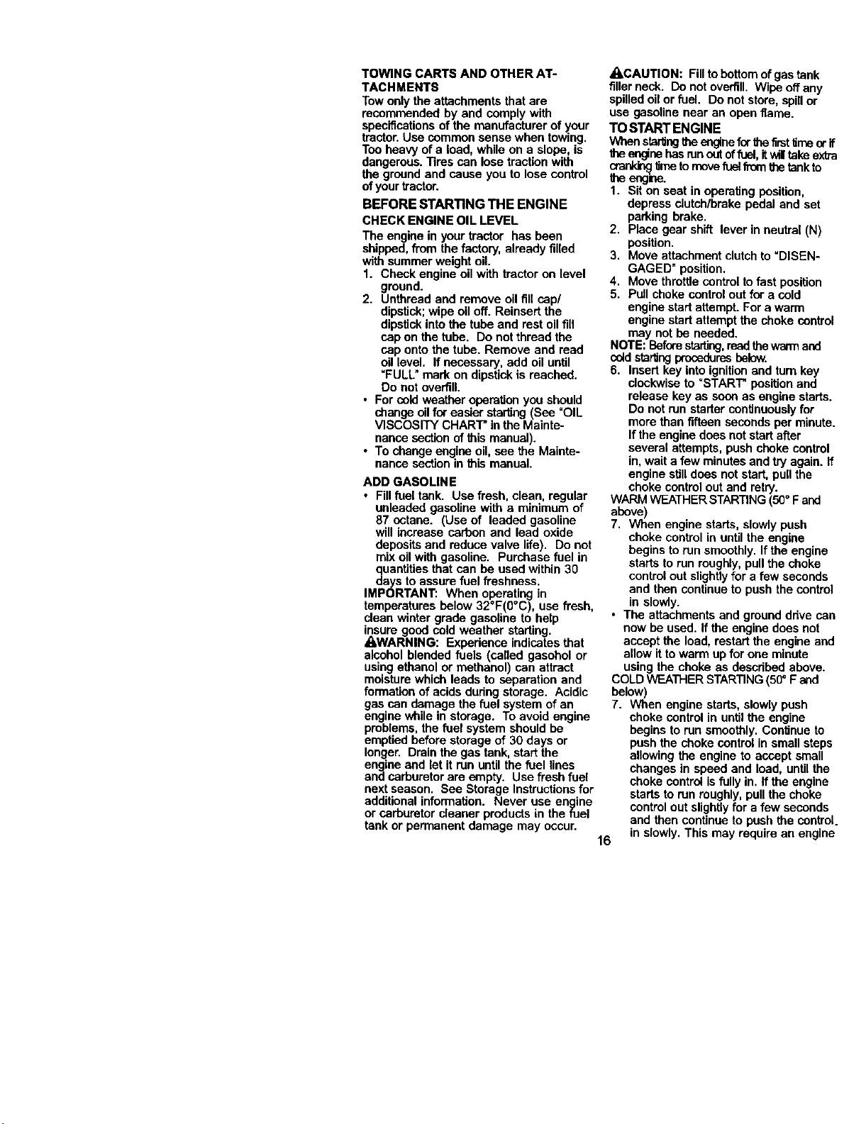
TO ADJUST GAUGE WHEELS
Gauge wheels are properly adjusted
when they are slightlyoff the ground
when mower is at the desired cutting
height in operating position. Gauge
wheels then keep the deck in proper
position to help prevent scalping in most
terrain conditions.
NOTE: Be sure tractorison a fiat level
surface.
1. Lower mower and adjust mower to
desired cutting height.
2. Remove retainer spring and clevis pin
which secure each gauge wheel bar.
3. Lower gauge wheels to ground. Raise
gauge wheels slightlyto align holes in
bracket and gauge wheel bar and
insert clevis pin. Gauge wheels
should be slightlyoff the ground.
4. Replace retainer spdng into clevis pin.
5. Be sure all gauge wheels are in the
same setting.
IMPORTANT: Be sure to readjust gauge
wheels if you change the cuttingheight
of the mower deck.
Retainer
Spring
Pin
TO OPERATE MOWER
Your tractor is equipped with an operator
presence sensing switch. Any attempt by
the operatorto leave the seat with the
engine running and the attachment clutch
engaged will shut off the engine.
1. Select desired height of cut.
2. Lower mower with attachment llft
control.
3. Start mower blades by engaging
attachment clutchcontrol.
TO STOP MOWER BLADES -
disengage attachment clutch control.
,_CAUTION: Do not operate the mower
withouteither the entire grass catcher,on
mowers so equipped, or the deflector
shield in place•
AttachmentClutch
SwitchPullOutTo
_Attachrnent L_
Lever High
S_ n
:_:_ Low
' Position
_ SD;_ifle;_tOr
TO OPERATE ON HILLS
_CAUTION: Do not drive up or down
hills with slopes greater than 15° and do
not drive across any slope. Use the slope
guide provided at the back of this manual.
• Choose the slowest speed before
starling up or down hills.
• Avoid stopping or changing speed on
hills.
• If slowing is necessary, move throttle
control lever to slower position.
• If stopping is absolutely necessary,
push clutch/brake pedal quickly to
brake positionand engage parking
brake.
• Move gearshift lever to 1st gear and
range shift lever to low (L) position. Be
sure you have allowed room for tractor
to roll slightly as you restart movement.
• To restart movement, slowly release
parking brake and clutch/brake pedal.
• Make all turns slowly.
TO TRANSPORT
• Raise attachment lift to highestposition
with attachment liftcontrol.
• When pushing or towingyour tractor,
be sure gearshift lever is in neutral (N)
position.
• Do not push or tow tractor at more than
five (5) MPH.
NOTE: To protecthoodfrom damage
when transportingyour tractor on a truck
or a trailer, be sure hoodis closed and
secured to tractor. Use an appropriate
means of tying hood to tractor (rope, cord,
15 etc.).
TOWINGCARTSANDOTHERAT-
TACHMENT8
Towonlytheattachments that are
recommended by and comply with
specificationsof the manufacturer of your
tractor.Use common sense when towing.
Tooheavy of a load while on a slope, is
dangerous. "nrescan rosetraction w th
the ground and cause you to lose control
of yourtractor.
BEFORE STARTING THE ENGINE
CHECK ENGINE OIL LEVEL
The engine in your tractor has been
shipped, from the factory, already filled
with summer weight oil
1. Check engine oil with tractor on level
ground.
2. Unthread and remove oil fill cap/
dipstick;wipe oil off. Reinsert the
dipstickinto the tube and rest oil fill
cap on the tube. Do not thread the
cap onto the tube. Remove and read
oil level. If necessary, add oil until
"FULL" mark on dipstickis roached.
Do not overfill.
• For cold weather operation you should
change oil for easier starting(Sea OIL
VISCOSITY CHART' In the Mainte-
nance section of this manual).
• To change engine oil, see the Mainte-
nance section in this manual.
ADD GASOLINE
• Fill fuel tank. Use fresh, clean, regular
unleaded gasoline with a minimum of
87 octane. (Use of leaded gasoline
will increase carbon and lead oxide
depositsand reduce valve life). Do not
mix oil with gasoline. Purchase fuel in
quantitiesthat can be used within 30
days to assure fuel freshness.
IMPORTANT: When operating in
temperatures below 32°F(0°C), use fresh,
clean winter grade gasoline to help
insure 9ood cold weather starting.
_WARNING: Expedence indicatesthat
alcohol blended fuels (called gasohol or
using ethanol or methanol) can attract
moisture which leads to separation and
formation of acids dudng storage. Acidic
gas can damage the fuel systemof an
engine while in storage. To avoid engine
problems, the fuel system should be
emptied before storage of 30 days or
longer. Drain the gas tank, start the
engine and let it run until the fuel lines
and carburetor are empty. Use fresh fuel
next season. See Storage Instructions for
additional information. Never use engine
or carburetor cleaner products in the fuel
tank or permanent damage may occur.
16
A, CAUTION: Filltobottom of gas tank
filler neck. Do notoverfill. Wipe off an'
spilled oil or fuel, Do not store, spillor
use gasoline near an open flame.
TO START ENGINE
When stadJngtha enginefar thefirsttime q
theer_ne hasmn outoffuoi, itwll take e
orarPJ_ timeto movefuel fromthe tankto
the enge=e.
1. Sit on seat in operating position,
depress oiutch/brake pedal and set
parking brake.
2. Place gear shift lever in neutral (NI
position.
3. Move attachment clutchto "DISEN-
GAGED" position.
4. Move throttle control to fast positior
5. Pull choke controlout for a cold
engine start attempt. For a warm
engine start attempt the choke cont
may not be needed.
NOTE: Beforestarting,readthe warman_
coldstartingproceduresbelow.
6. Insert key thto ignition aed turn key
clockwise to "START" position and
release key as soon as engine star
Do not run starter continuouslyfor
more than fifteen secondsper mint
If the engine does notstart after
several attempts, push choke contl
in, wait afew minutesand try again
engine stiltdoes not start, pullthe
choke control outand retry.
WARMWEATHERSTARTING(50+Fan(
above)
7. When engine starts, slowly push
choke control in untilthe engine
begins to run smoothly. If the engk
starts to run roughly,pull the cbek{
control outslightlyfor a few sacon_
and than continue to push the conb
in slowly.
• The attachments and ground ddve e
now be used. If the engine does not
accept the load, restart the engine a
allow itto warm upfor one minute
using the choke as descdbed above
COLD WEATHER STARTING(50° F and
below)
7. When engine starts, slowly push
choke control in until the engine
begins to run smoothly. Continue b
push the choke controlin small ste
allowing the engine to accept smal
changes in speed and load, until t|
choke control is fully in. If the engir
starts to run roughly, pull the chok(
controlout slightly for a few secon<
and than continue to push the con1
in slowly. This may require an eng
warm-up period from several seconds
to several minutes, depending on the
temperature.
• The attachments can be used dudng
the engine warm-up period and may
require the choke control be pulled out
slightly.
NOTE: ifata highaRitude(above3000 feet)
or incoldtemperatures(below32 F)the
c_buretorfuel mixturemay seed tobe
a_usted for bestengineperformance.See
"TOADJUSTCARBURETOR"in theService
and A_ustmentsssc_on ofIbismanual
MOWING TIPS
• Tire chains cannot be used when the
mower housing is attached to tractor.
• Mower should be propedy leveled for
best mowing performance. See "TO
LEVEL MOWER HOUSING" in the
Service and Adjustments section ofthis
manual.
• The left hand side of mower should be
used for trimming.
• Ddve so that clippingsare discharged
onto the area that has been cut. Have
the cut area to the dght of the tractor.
Thiswill resultin a more even distribu-
tion of clippingsand more uniform
cutting.
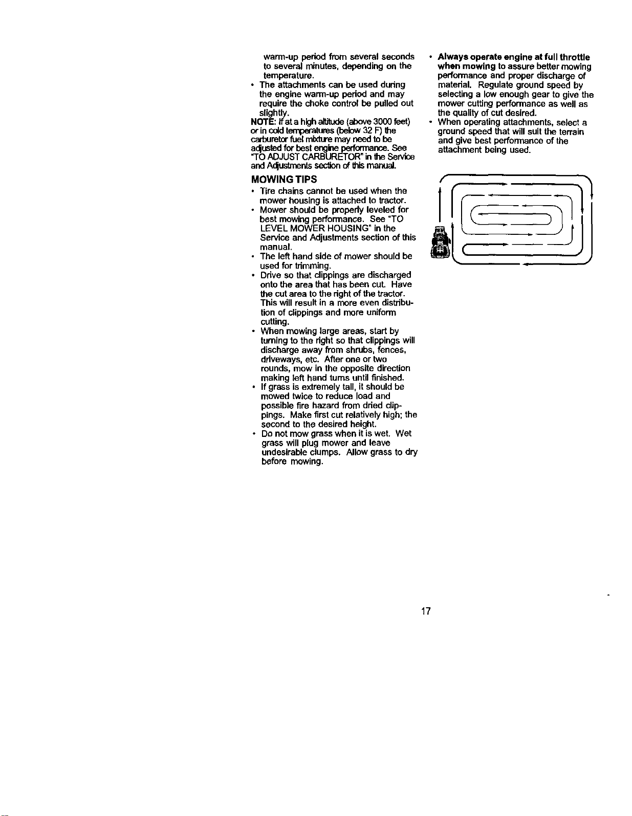
• When mowing large areas, start by
turningto the dghtso that clippingswill
discharge away from shrubs, fences,
ddveways, etc. After one or two
rounds, mow in the opposite direction
making left hand turns untilfinished.
• If grassis extremely tall, it shouldbe
mowed twice to reduce load and
possiblefire hazard from dded clip-
pings. Make first cut relatively high;the
second to the desired height.
• Do not mow grass when it iswet. Wet
grass will plug mower and leave
undesirable clumps. Allow grass to dry
before mowing.
• Always operate engine at full throttle
when mowing to assure better mowing
performance and proper discharge of
matedal Regulate ground speed by
selecting a low enough gear to give the
mower cuffingperformance as well as
the qualityof cut desired
• When operating attachments, select a
ground speed that will suit the terrain
and give best performance ofthe
attachment being used
(
1
17
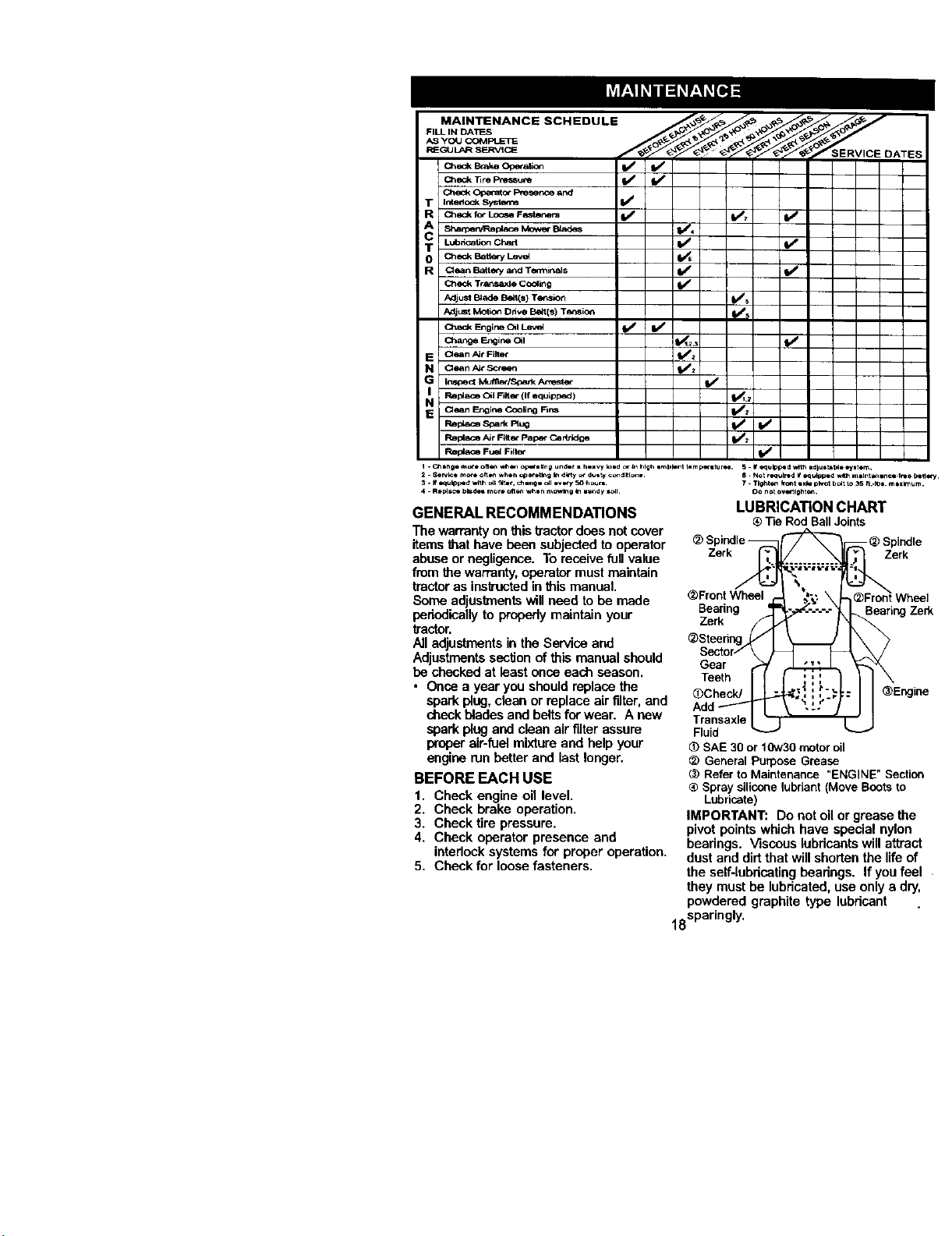
MAINTENANCE SCHEDULE
FILL IN DA_-S
AS yOLI CCMPLETE
P_EG_JLARSERVtCE _ERVICE DATES
Ched_BakeO_a_c_ I/' V'
C_eck _re P_sssu_ V' V"
Check Ope_ato_ PmsePo_ and
T In_oc_sy,,_r,_ V'
R ChQckro_LOO_ Fa_,_ I,/ V', I/
ShamerVRspi_ceMowerBJades 1/4
T kubacati= Cha,1 IV_ V'
O checkB,_tV,_yL,_,_
R aean Battery and Terminals If V j
Check TraPs,axle COOling
Adjust B_ade BetKs} Te_._on t,/5
Adju_ Motic_ Dnve Be_t(s) Tl_sio_ I_s
Check Engirm OqlLev_ I_ If
c_angeEngi_al t_,=._ t/
E Qe_n Air Filler I_ 2
N Qean A_r Screen I_'_
G Inspe_ I_en_lspa_k ,_e_te_
I_ R_I_* C_I FiR_ (If _uipl_d ) _,=
E Clean Er:gir_ COOling Fins It_a
ReplaceFue_Fille_ IV/
GENERAL RECOMMENDATIONS
The warranty onthis tractordoes not cover
items that have been subjected to operator
abuse or negligence. To receive fullvalue
from the warranty,operator mustmaintain
tractoras ins_zuctedin this manual.
Some adjustmentswillneed to be made
periodically to properlymaintain your
tractor.
All adjustments in the Service and
Adjustmentssection of this manual should
be checked at least once each season.
• Once a year you should replace the
spark plug,clean or replace air filter, and
check blades and beltsfor wear. A new
spark plugand clean air filter assure
proper air-fuel mixtureand help your
engine ran better and last longer.
BEFORE EACH USE
1. Check engine oil level.
2. Check brake operation.
3. Check tire pressure.
4. Check operator presence and
interlock systems for proper operation.
5. Check for loose fasteners.
s. Not r,,_*d # equ_pped web mllnt_encl.freo bl _t,.*_.
7 1191_tenfro_t •X_ p;,,ot bo_tto 35 h..t_s m,x_mum.
Oo not ove_lghte_.
LUBRICATION CHART
® Tie RodBallJoints
Spindle
Zerk Zerk
_Front Wheel
Bearing
Zerk
_)Steedr_
Gear
Teeth
_CheckJ
_earingZed_
Transaxle
Fluid
SAE30or 10w30motoroil
_) General purposeGrease
(_ RefertoMaintenance"ENGINE"Section
® Spraysiliconelubriant (MoveBootsto
Lubricate)
IMPORTANT: Do not oil or grease the
pivot points which have special nylon
bearings. Viscous lubricantswill attract
dust and dirtthat will shortenthe lifeof
the self-lubricatingbeadngs. If youfeel
they must be lubricated, use onlya dry,
powdered graphite type lubdcant
18sparingly'
TRACTOR
Always observe safety rules when
performing any maintenance.
BRAKE OPERATION
If tractorrequires morethan six (6) feet
stoppingdistance at high speed in
highestgear, then brake must be ad-
justed. (_ee "TO ADJUST BRAKE in the
Service and Adjustments section of this
manual).
TIRES
i Maintain proper air pressure in a, tires
(See "PRODUCT SPECIFICATIONS
section of this manual).
Keep tires free ofgasoline, oil,or insect
controlchemicals which can harm
rubber.
• Avoid stumps,stones, deep ruts, sharp
objects andother hazards that may
cause tire damage.
NOTE: To seal tire punctures and prevent
fiat tires due to slow leaks, tire sealant
may hepurchased from your local parts
dealer. Tire sealant also prevents tire dry
rotand corrosion.
OPERATOR PRESENCE SYSTEM
Be sure operator presence and intedock
systemsare working properly. If your
tractor does not functionas described,
repair the problem immediately.
• The engine should not start unless the
clutch/brake pedal is fully depressed
and attachement clutchcontrol is in the
disengaged position.
• When the engine is running, any
attempt bythe operator to leave the
seat without first settingthe parking
brake should shut offthe engine.
• When the engine is running and the
attachment dutch is engaged, any
attempt by the operator to leave the
seat should shut offthe engine.
• The attachment dutch should never
operate unless the operator is in the
seat.
BLADE CARE
For best results mower blades must be
kept sharp. Replace bent or damaged
blades.
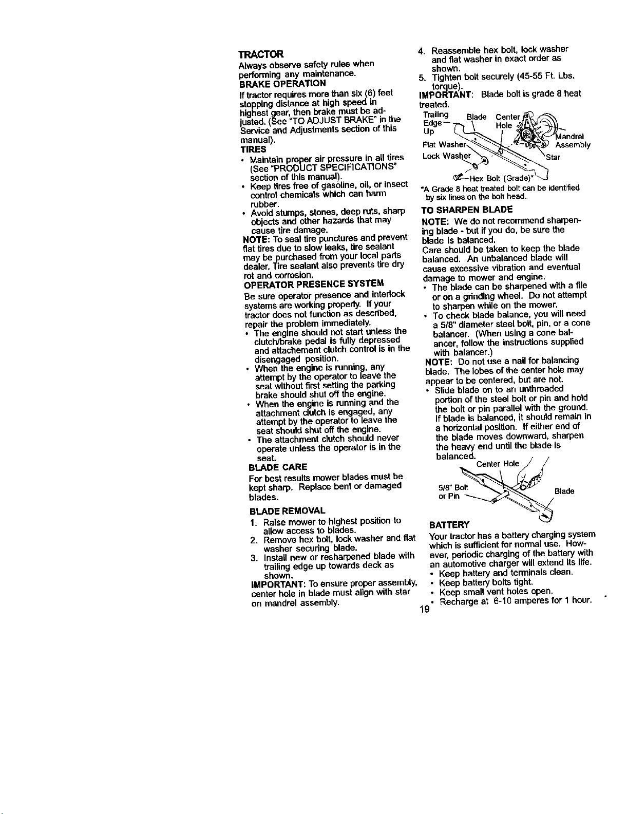
BLADE REMOVAL
1. Raise mower to highest positionto
allow access to blades.
2. Remove hex bolt, lock washer and fiat
washer securing blade.
3. Install new or resharponed blade with
trailing edge up towards deck as
shown.
IMPORTANT: To ensure proper assembly,
center hole in blade must alignwith star
on mandrel assembly.
4. Reassemble hex bolt, lock washer
and flat washer in exact order as
shown.
5. Tighten bolt securely (45-55 Ft. Lbs.
torque.
MPORTANT: Blade boltis grade 8 heat
treated.
Trailing Blade Center
Hole ,
Up
Assembly
_---Hex Bolt(Grade)
*A Grade8 heattreatedboltcanbeidentified
bysixlinesonthebolthead.
TO SHARPEN BLADE
NOTE: We do notrecommend sharpen-
ing blade - butif you do, be sure the
blade is balanced.
Care should be taken to keep the blade
balanced, An unbalanced blade will
cause excessive vibration and eventual
damage to mower and engine,
• The blade can be sharpened with a file
or on a grindingwheel, Do not attempt
to sharpen while on the mower.
• To check blade balance, you will need
a 5/6" diameter steel bolt, pin, or a cone
balancer. (When using a cone bal-
ancar, follow the instructionssupplied
with balancer.)
NOTE: Do not use a nail for balancing
blade. The lobes of the center hole may
appear to be centered, but are not.
• Slide blade on to an unthreaded
portion of the steel bolt or pin and hold
the bolt or pin parallel with the ground.
If blade is balanced, it should remain in
a hodzontal position. If either end of
the blade moves downward, sharpen
the heavy end until the blade is
balanced.
CenterHo_e / /
5/8 Bolt
orPin Blade
BATTERY
Your tractorhas a batterycharging systen
which is sufficientfor normal use. How-
ever, pededic charging of the battery with
an automotive charger will extend its life.
• Keep battery and terminals clean,
• Keep battery bolts tight.
• Keep small vent holes open.
• Recharge at 6-10 amperes for 1 hour.
19
NOTE: The originalequipment batteryon
your tractor is maintenance free. Do not
attempt to open or remove caps or covers.
Adding or checking level of electrolyte is
notnecessary.
TO CLEAN BATTERY AND TERMINALS
Corrosionand dirt on the battery and
terminalscan cause the battery to "leak"
power,
1. Remove terminal guard,
2. Disconnect BLACK battery cable first
then RED battery cable and remove
batteryfrom tractor.
3. Rinse the batterywith plain water and
dry,
4. Clean terminals and battery cable
ends with wire brush until bdght.
5. Coat terminals with grease or petro-
leum jelly.
6. Reinstall battery (See "REPLACING
BATTERY" in the SERVICE AND
ADJUSTMENTS sectionof this
manual),
V-BELTS
Check V-belts for detedoration and wear
after 100 hours of operation and replace if
necessary, The belts are not adjustable.
Replace belts if they begin to slipfrom
wear.
TRANSAXLE COOLING
Keep transaxle tree from build-up of dirt
and chaff whichcan restdct cooling,
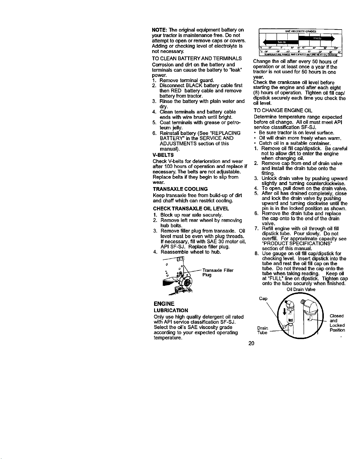
CHECK TRANSAXLE OIL LEVEL
1. Block up rear axle securely.
2. Remove left rear wheel by removing
hub bolts.
3. Remove filler plugfrom transaxle. Oil
level must be even with plugthreads.
If necessary, fillwith SAE 30 motor oil,
API SF-SJ. Replace fillerplug.
4. Reassemble wheel to hub.
_ TransaxleFiller
Ptug
ENGINE
LUBRICATION
Only use high quality detergent oil rated
withAPI service classificationSF-SJ,
Select the oil'sSAE viscositygrade
according to your expected operating
temperature,
Change the oil after every 50 hours of
operationor at least once a year if the
tractor is not usedfor 50 hours in one
year.
Check the crankcase oil level before
starting the engine and after each eight
(8) hours ofoperation, Tighten oil fillcap/
dipsticksecuro[yeach time you check the
oil level.
TO CHANGE ENGINE OIL
Determine temperature range expected
beforeoil change. All oil must meet API
service classificationSF-SJ.
• Be sure tractor ison level surface,
• Oil willdrain more freely when warm,
• Catch oil in a suitable container.
1. Remove oil fill cap/dipstick, Be careful
notto allow dirt to enter the engine
when changing oil.
2. Remove cap from end of drain valve
and install the draintube onto the
fitting.
3. Unlock drain valve by pushing upward
slightly and fuming counterclockwise.
4. To open, pull down on the drainvalve.
5. After oil has drained completely, close
and lock the drain valve by pushing
upward and turning clockwiseuntil the
pin is in the locked positionas shown.
6. Remove the drain tube and replace
the cap onto to the end of the drain
valve.
7. Refill engine with oil throughoil fill
dipsticktube, Pour slowty. Do not
overfill. For approximate capacity see
"PRODUCT SPECIFICATIONS"
section of this manual.
8, Use gauge on oil fill cap/dipstick for
checkinglevel. Insert dipstickintothe
tube and rest the oil fillcap on the
tube. Do notthread the cap onto the
tube when taking reading, Keep oil
at "FULL" line on dipstick. Tighten cap
onto the tube securely when finished.
Drain
Tube- •
Oil Drain Valve
i __ Closed
and
Locked
Position
2O
CLEAN AIR SCREEN
Air screen must be keptfree ofdirt and
chaff to prevent engine damage from
overheating. Clean with a wire brush or
compressed air to remove dirt end
stubborndried gum fibers.
CLEAN AIR INTAKE/COOLING AREAS
To insure proper cooling, make sure the
grass screen, cooling fins, and other
external surfaces of the engine are kept
clean at all times.
Every 100 hours of operation (mere often
under extremely dusty,dirty conditions),
remove the blower housing and other
cooling shrouds. Clean the sooling fins
and external surfaces as necessary.
Make sure the cooling shrouds are
reinstalled.
NOTE: Operating the engine with a
blocked grass screen, dirtyor plugged
coolingfins, and/or cooling shrouds
removed will cause engine damage due
to overheating.
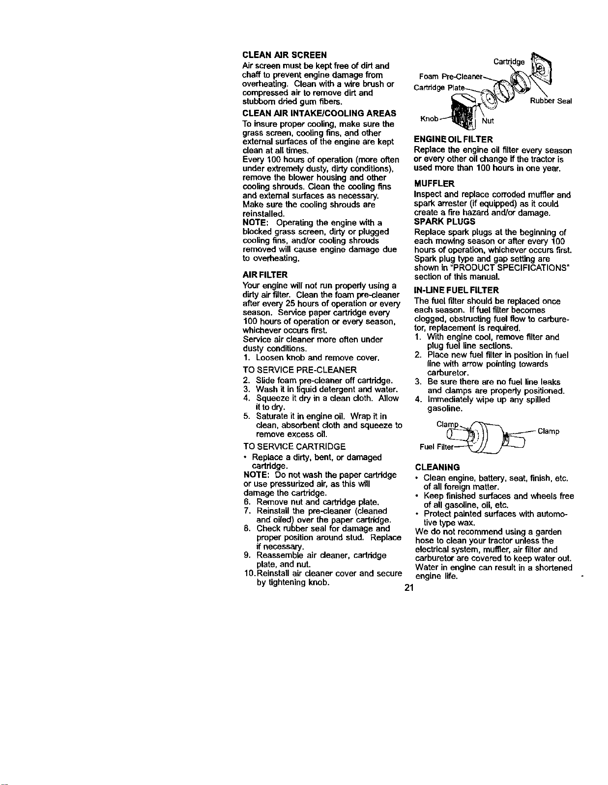
AIR FILTER
Your engine will not run properly using a
dirty air filter. Clean the foam pre.-cleaner
after every 25 hours of operation or every
season. Service paper cartridge every
100 hours of operation or every season,
whichever occurs first.
Service air cleaner more often under
dusty conditions.
1. Loosen knob and remove cover.
TO SERVICE PRE-CLEANER
2. Slide foam pre-cleaner off cartridge.
3. Wash it in liquid detergent and water.
4. Squeeze itdry in a clean cloth. Allow
itto dry.
5. Saturate it in engine oil. Wrap it in
clean, absorbent cloth and squeeze to
remove excess oil.
TO SERVICE CARTRIDGE
• Replace a dirty, bent, or damaged
cartridge.
NOTE: Do not wash the paper cartridge
or use pressurized air, as thiswill
damage the cartridge.
6. Remove nut and cartridge plate.
7. Reinstall the pre-cleaner (cleaned
and oiled) over the paper cartridge.
8. Check rubber seal for damage and
proper positionaround stud. Replace
if necessary.
9. Reassemble air cleaner, cartddge
plate, and nut.
10.Reinstall air cleaner cover and secure
by tighteningknob.
Foam
Cartridge
Rubber Seal
Nut
ENGINE OIL FILTER
Replace the engine oil filter every season
or every other oil change if the tractor is
used more than 100 hours in one year.
MUFFLER
Inspect and replace corroded muffler and
spark attester (if equipped) as it could
create a fire hazard and/or damage.
SPARK PLUGS
Replace spark plugs at the beginning of
each mowing season or after every 100
hours of operation, whichever occurs first.
Spark plug type and gap settingare
shown in =PRODUCT SPECIFICATIONS"
section of this manual.
IN-LINE FUEL FILTER
The fuel filtershould be replaced once
each season. If fuel filter becomes
clogged, obstructingfuel flow to carbure-
tor, replacement is required.
1. With engine cool, remove filter and
plug fuel line sections.
2. Place new fuel filter in position in fuel
line with arrow pointingtowards
carburetor.
3. Be sure there are nofuel line leaks
and damps are propedy positioned.
4. immediately wipe up any spilled
gasoline.
Clamp Clamp
Fuel Filt:_
CLEANING
• Clean engine, battery, seat, finish, etc.
of all foreign matter.
• Keep finished surfaces and wheels free
of all gasoline, oil, etc.
• Protect painted surfaces with automo-
tive type wax.
We do not recommend using a garden
hose to clean your tractor unlessthe
electricalsystem, muffler, air filter and
carburetor are covered to keep water out.
Water in engine can result in a shortened
engine life.
21
CAUTION: BEFORE PERFORMING ANY SERVICE ORADJUSTMENTS:
l. Depress clutch/brake pedal fully and set parking brake.2. Place gearshift lever in neutral (N)position.
3. Place attachment clutch in "DISENGAGED" position.
4. Turn ignitionkey "OFF" and remove key,
5. Make sure the blades and all moving parts have completely stopped,
6. Disconnect spark plug wire from spark plug and place wire where it cannot
come in contactwith plug.
TRACTOR
TO REMOVE MOWER
1. Place attachment clutch in "DISEN-
GAGED" position.
2. Turn height adjustment knob to lowest
setting.
3. Lower mower to its lowest position.
4. Remove retainer spring holding anti-
swaybar to chassis bracket and
disengage anti-swaybar from bracket,
5. Remove four retainer springs from
front plate assembly and remove
plate.
6. Remove retainer springs from
suspension arms at deck and disen-
gage arms from deck.
7. Raise attachment lift to its highest
position.
8. Slide mower forward and remove belt
from electric clutchpulley.
9. Slide mower out from under rightside
oftractor.
TO INSTALL MOWER
Follow procedure described in "INSTALL
MOWER AND DRIVE BELT"in the
Assembly section of this manual.
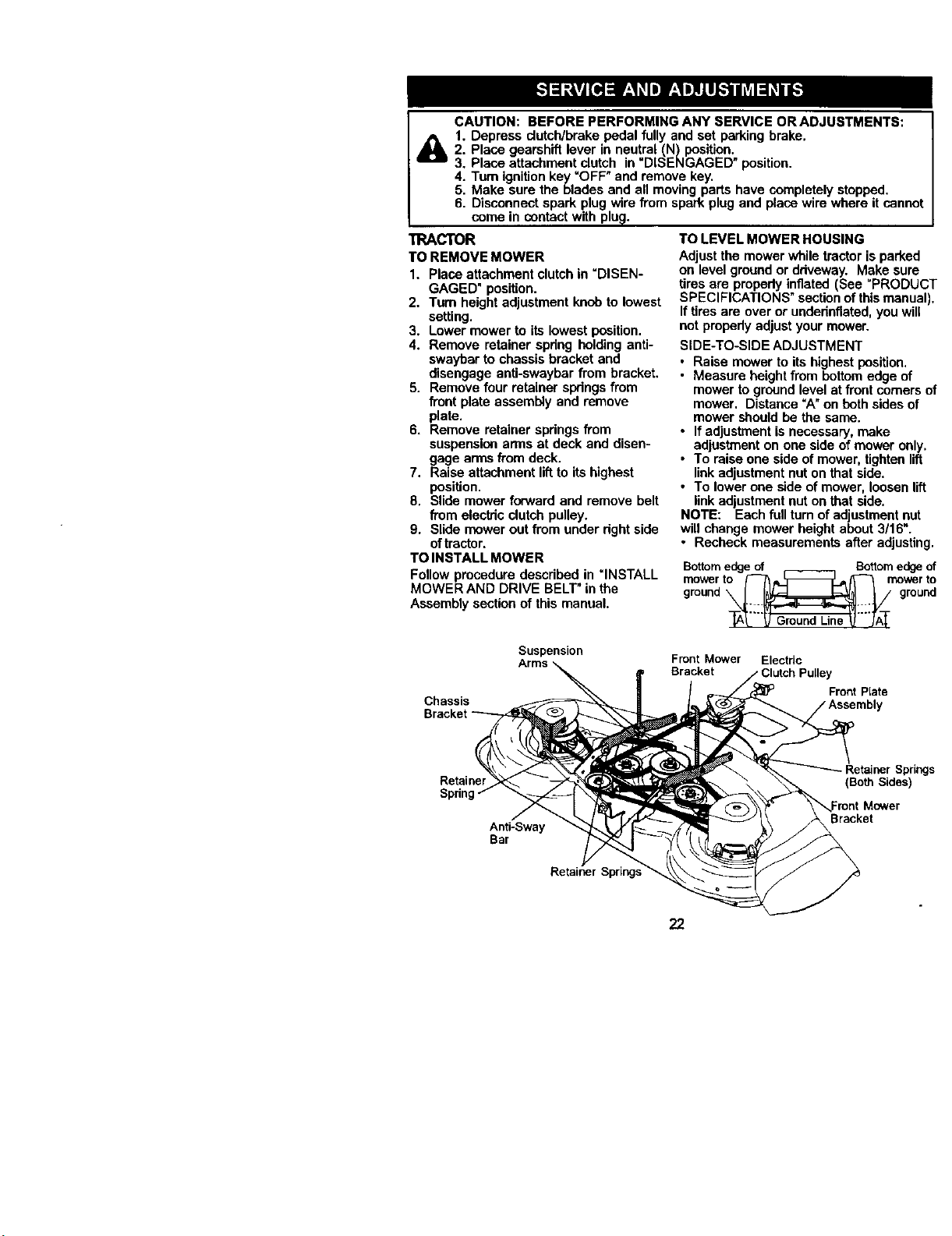
TO LEVEL MOWER HOUSING
Adjust the mower while tractor is parked
on level ground or driveway. Make sure
tires are propedy inflated (See "PRODUCT
SPECIFICATIONS" section ofthis manual).
If tires are over or underinflated,you will
not properly adjust your mower.
SIDE-TO-SIDE ADJUSTMENT
• Raise mower to its highest position,
• Measure height from bottomedge of
mower to groundlevel at front comers of
mower, Distance =A"on both sides of
mower should be the same.
• If adjustment is necessary, make
adjustment on one side of mower only.
• To raise one side of mower, tighten lift
linkadjustment nut on that side.
• To lower one side of mower, loosen lift
linkadjustment nut on that side.
NOTE: Each futlrum of adjustmentnut
will change mower height about 3/16".
• Recheck measurements after adjusting.
Bottomedgeof Bottomedgeof
gmr°uW_n_t_n%roW_rnt _
Chassis
Bracket
Suspension
Arms
Front Mower Electnc
Bracket Pulley
Front Plate
Retainer
Spnn
Anti-Sway
Bar
Retainer
• Retainer Springs
22
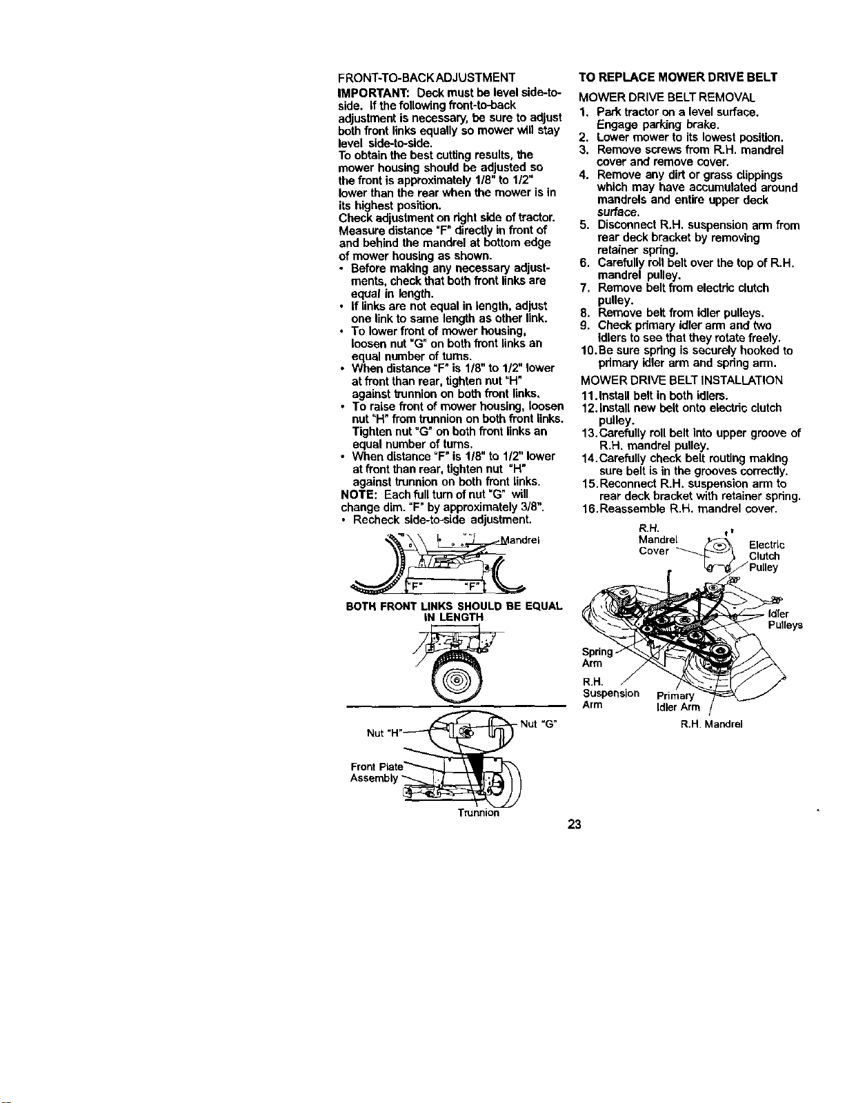
FRONT:rO-BACKADJUSTMENT
IMPORTANT: Deck must be level side-to-
side. If the followingfront-b_back
adjustmentis necessary, be sure to adjust
bothfront links equally so mower will stay
level side-to-side.
To obtainthe best cuttingresults,the
mower housing should be adjusted so
the frontis approximately 1/8" to 1/2"
lower than the rear when the mower is in
its highest position.
Check adjustmenton dght side oftractor.
Measure distance "F" directlyin front of
and behind the mandrel at bottom edge
of mower housing as shown.
• Before making any necessary adjust-
ments, check that both front links are
equal in length.
• If linksare not equal in length, adjust
one link to same length as ether link.
• To lower front of mower housing,
loosen nut "G" on both front links an
equal number of turns.
• When distance "F" is 1/8"to 1/2" lower
at front than rear, tightennut "H"
against trunnionon both front links,
• To raise front of mower housing, loosen
nut=H" from trunnionon both front links.
Tighten nut"G" onboth front links an
equal number of turns.
• When distance °F'is 1/8"to 1/2"lower
at front than rear, tighten nut "H"
against trunnionon beth front links.
NOTE: Each full turnofnut =G" will
change dim. "F"by approximately 3/8".
• Recheck side-to-side adjustment.
_rel
BOTH FRONTLINKS SHOULDBE EQUAL
IN LENGTH
- Nut "G"
TO REPLACE MOWER DRIVE BELT
MOWER DRIVE BELT REMOVAL
1. Park tractoron a level surface.
Engage parking brake.
2. Lower mower to its lowest position.
3. Remove screws from R.H. mandrel
cover and remove cover.
4. Remove any dirt or grass clippings
which may have accumulated around
mandrels and entire upper deck
surface.
5. Disconnect R.H. suspension arm from
rear deck bracket by removing
retainer spdng.
6. Carefully roll belt over the top of R.H.
mandrel pulley.
7. Remove bolt from elect_c clutch
pulley.
8. Remove belt from idler pulleys.
9. Check primary idlerarm and two
Idlers to see that they rotate freely.
10.Be sure spring is securely hooked to
pdmary idler arm and spdng arm.
MOWER DRIVE BELTINSTALLATION
11.Install belt in both idlers.
12.Install new belt onto electdc clutch
pulley.
13.Carefully roll belt into upper groove of
R.H. mandrel pulley.
14.Carefully check belt muting making
sure belt is in the grooves correctly.
15.Reconnect R.H. suspension arm to
rear deck bracket with retainer spdng.
16.Reassemble R.H. mandrel cover.
Mandrel Electric
Cover
Spdng
Arm
R.H,
Suspension
Arm
Primary
Idler Arm
R.H. Mandrel
. Idler
Pulleys
Assembly
Trunnion
23
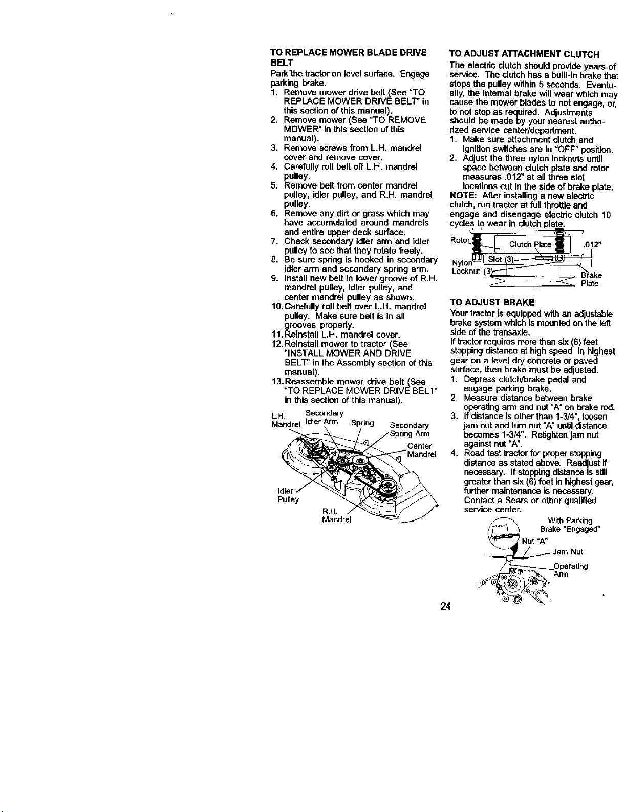
TO REPLACE MOWER BLADE DRIVE
BELT
Park_'le tractor on levelsurface. Engage
parking brake.
1. Remove mower ddve holt (See "TO
REPLACE MOWER DRIVE BELT" in
this section of this manual).
2. Remove mower (See =TO REMOVE
MOWER" in this section of this
manual).
3. Remove screws from L.H. mandrel
cover and remove cover.
4. Carefully rollbelt off LH. mandrel
pulley.
5. Remove holt from center mandrel
pulley, idler pulley, and R.H. mandrel
pulley.
6. Remove any dirt or grass which may
have accumulated around mandrels
and entire upper deck surface.
7. Check secondary idler arm and idler
pulley to see that they rotate freely.
8. Be sure spdng is hooked in secondary
idler arm and secondary spring arm.
9. Install new belt in lower groove of R.H.
mandrel pulley, idler pulley, and
center mandrel pulley as shown.
10.Carefully roll beltover L.H. mandrel
pulley. Make sure belt is in all
grooves properly.
11.Reinstall L.H. mandrel cover.
12. Reinstall mower to tractor (See
"INSTALL MOWER AND DRIVE
BELT" in the Assembly section ofthis
manual).
13.Reassemble mower drive belt (See
"TO REPLACE MOWER DRIVE BELT"
in this section of this manual).
LH. Secondary
Mandrel IdlerArm Spring Secondary
SpringArm
Center
Idler/ _'-_"'_,.p_ '_YJ_
Po,ey "-.
R.H.
TO ADJUST ATTACHMENT CLUTCH
The electdc clutchshould provideyears of
service. The clutch has a built-inbrake that
stops the pulleywithin 5 seconds. Eventu-
ally, the intemal brake will wear which may
cause the mower blades to not engage, or,
tonot stopas required. Adjustments
should be made by your nearest autho-
rized service center/department.
1. Make sure attachment clutchand
ignitionswitchesare in "OFF" position.
2. Adjust the three nylon Iocknutsuntil
space between clutchplate and rotor
measures .012" at all three slot
locationscut in the side of brake plate.
NOTE: After installinga new electdc
clutch,run tractor at full throttleand
engage and disengage electdc clutch 10
cycles towear in clutchplate.
R°t°_ C,utch p,ate ri_J 012 .
Slot 3
Nylon_J_lSIo'( )-- _ I I
Locknut(3)_ _ 1./ B'B_rake
_ Plate
TO ADJUST BRAKE
Your tractor isequipped with anadjustable
brake systemwhichismountedon the left
side of the transaxle.
Iftractor requiresmorethan six(6) feet
stoppingdistanceat highspeed in highest
gear on a level dry concrete or paved
surface, then brake must be adjusted.
1. Depress clutch/brakepedal and
engage parking brake.
2. Measure distance between brake
operatingarm and nut"A" on brakerod.
3. If distanceisotherthan 1-3/4",loosen
jam nut and turn nut"A" untildistance
becomes 1-3/4". Retightenjam nut
againstnut "A".
4. Road test tractorfor properstopping
distanceas statedabove. Readjustif
necessary. If stoppingdistanceisstill
greater than six (6)feet in highestgear,
furthermaintenance is necessary.
Contact a Sears or other qualified
service center.
24
With Parking
I Brake "Engaged"
Nut "A"
_.._ Jam Nut
_Operating
Arm
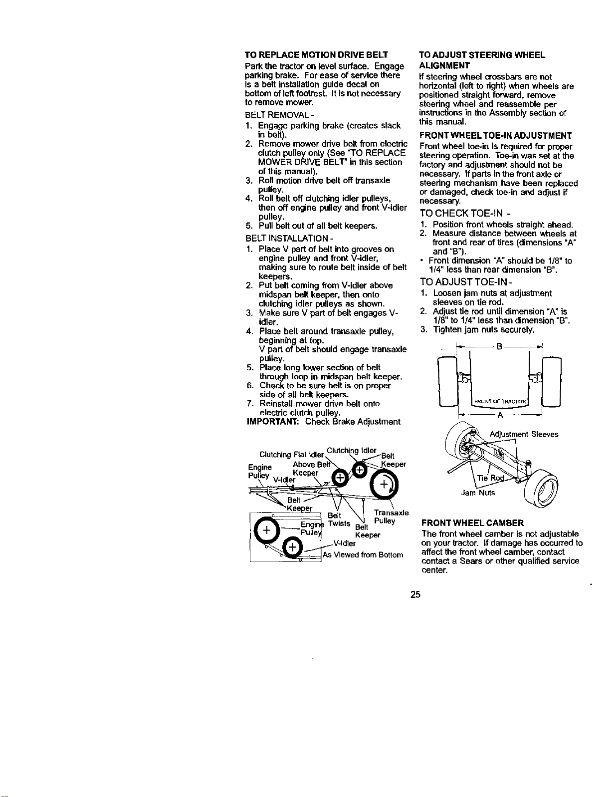
TO REPLACE MOTION DRIVE BELT
Park the tractor on level surface. Engage
parking brake. For ease ofservice there
is a bolt installation guide decal on
bottom ofleft footrest. Itis notnecessary
to remove mower.
BELT REMOVAL-
1. Engage parking brake (creates slack
in belt).
2. Remove mower drive belt from electdc
clutch pulley only(See *TO REPLACE
MOWER DRIVE BELT" in thissection
ofthis manual).
3. Roll motiondrive belt off transaxle
pulley.
4. Roll belt off clutching idler pulleys,
then off engine pulley and front V-idler
pulley.
5. Pull bolt out of all bolt keepers.
BELT INSTALLATION -
1. Place V part of belt into grooves on
engine pulley and front V-idler,
making sure to route belt inside ofbelt
keepers.
2. Put bolt coming from V-idler above
midspan bolt keeper, then onto
clutchingidler pulleys as shown.
3. Make sure V part of belt engages V-
idler.
4. Place belt around transaxle pulley,
beginning at top.
V part of belt should engage transaxle
pulley.
5. Place long lower section of belt
through loop in midspan belt keeper.
6. Check to be sure bolt is on proper
side of all belt keepers.
7. Reinstall mower ddve belt onto
electric clutch pulley.
IMPORTANT: Check Brake Adjustment
Clutching Flat Idler_
Engine
Pulley
Transaxle
Belt Pulley
Twists Belt
Keeper
TO ADJUST STEERING WHEEL
ALIGNMENT
If steedng wheel crossbars are not
horizontal (left to fight) when wheels are
positionedstraight forward, remove
steedng wheel and reassemble per
instructionsin the Assembly sectionof
this manual.
FRONT WHEEL TOE-IN ADJUSTMENT
Frontwheel toe-in is required for proper
steering operation. Toe-in was set at the
factory and adjustment should not be
necessary. If parts inthe front axle or
steering mechanism have been replaced
or damaged, check toe-in and adjust if
necessary.
TO CHECK TOE-IN -
1. Positionfront wheels straight ahead.
2. Measure distance between wheels at
front and roar of tires (dimensions"A"
and "B").
• Frontdimension =Anshould be 1/8"to
1/4" less than rear dimension _E".
TO ADJUST TOE-IN -
1. Loosen jam nuts at adjustment
sleeves on tie rod.
2. Adjusttie rod untildimension _A"is
118"to 114"less than dimension °E".
3. Tighten jam nuts securely.
_B_
Adjustment Sleeves
Jam Nuts
FRONT WHEEL CAMBER
The front wheel camber is notadjustable
on your tractor. If damage has occurred to
affect the front wheel camber, contact
contact a Sears or other qualified service
center.
25
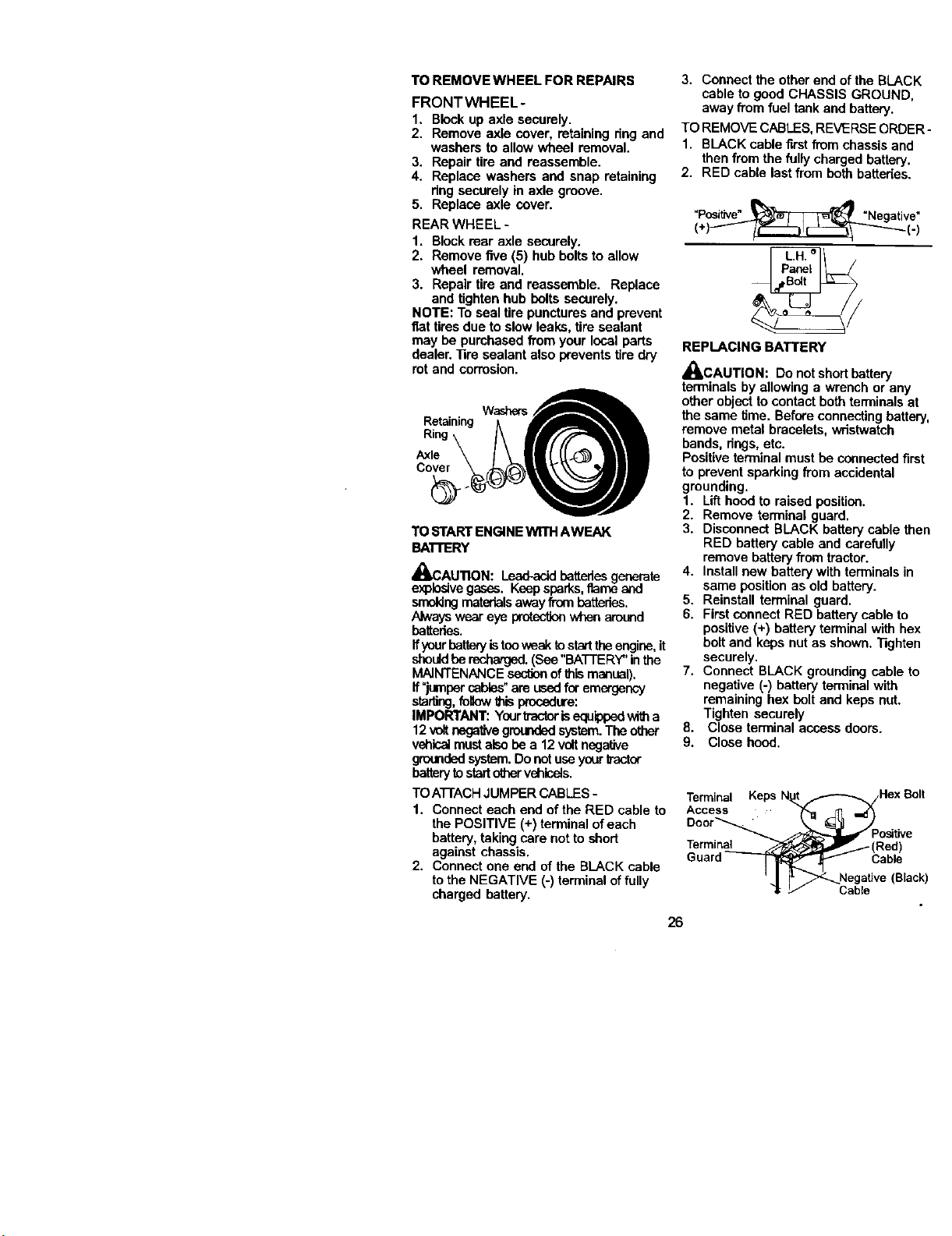
TO REMOVE WHEEL FOR REPAIRS
FRONTWHEEL-
1. Blockup axle securely.
2. Remove axle cover, retaining ring and
washers to allow wheel removal.
3. Repair tire and reassemble.
4. Replace washers and snap retaining
ring securely in axle groove.
5. Replace axle cover.
REAR WHEEL -
1. Blockrear axle securely.
2. Remove five (5) hub bolts to allow
wheel removal.
3. Repair tire and reassemble. Replace
and tightenhub bolts securely.
NOTE: To coal tire puncturesand prevent
fiat tires due to slowleaks, tire sealant
may be pumhased from your local parts
dealer. ]]re sealant also wevents tire dry
rot and corrosion.
Retaining;tWashers/__IL
R,ng\ /\ filrfF L\l
TO _I'ART ENGINEwrrH AWEAK
BATrERY
_I, CAU'nON: Lead-acidbatteriesgenerate
explosivegases. Keepsparks,flame and
smokingmaterialsawayfrombatteries.
Always wear eye protectionwhen around
batteries.
ffyourbatteryistooweektostarttheengine,it
shouldbe recharged.(See "BATTERY" inthe
MAINTENANCE _ of thismanual).
If"jumpercables"are usedfor emergency
staring,follow1hisprocedure:
IMPORTANT: Yourb'acterisequippedwitha
12 voltnegativegroundedsystem.The other
vehicalmustalsobea 12voltnegative
groundedsystem.Donotuseyourb'actor
batterytostartothervehicels.
TOATrACH JUMPER CABLES-
1, Connect each end of the RED cable to
the POSITIVE (+) terminal of each
battery, takingcare not to short
against chassis.
2. Connect one end of the BLACK cable
tothe NEGATIVE (-) terminal offully
charged battery.
3. Connect the other end of the BLACK
cable to good CHASSIS GROUND,
away from fuel tank and battery.
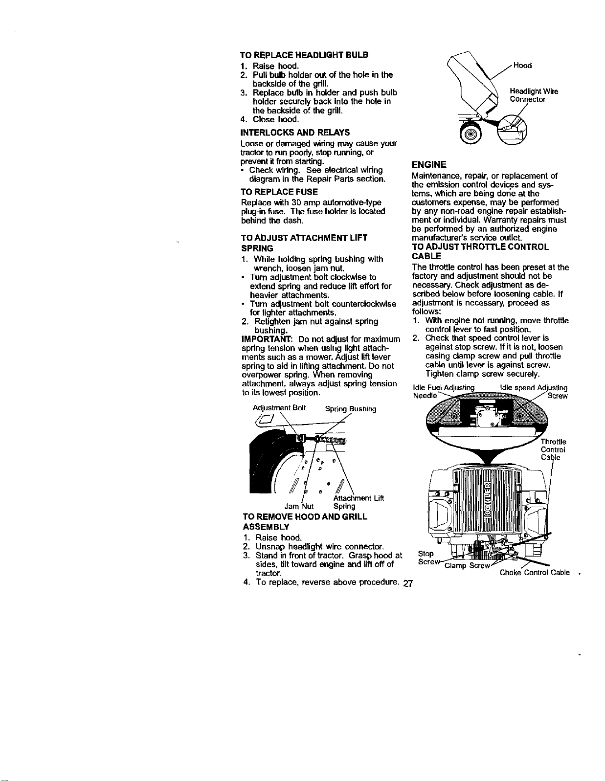
TO REMOVE CABLES,REVERSE ORDER -
1. BLACK cable firstfrom chassis and
then from the fully charged battery.
2. RED cable last from both battedes.
"Positive"__ ! "Negative"
(+i--I/i 7
REPLACING BATTERY
_CAUTION: Do notshort battery
terminals by allowing a wrench or any
other object to contact bothterminals at
the same time. Before connectingbattery,
remove metal bracelets, wristwatch
bands, dngs, etc.
Positive terminal must be connectedfirst
to prevent sparking from accidental
grounding.
1. Lift hoodto raised position.
2. Remove terminal guard.
3. Disconnect BLACK battery cable then
RED battery cable and carefully
remove batteryfrom tractor.
4. Installnew battery with terminals in
same position as old battery.
5. Reinstall terminal guard.
6. First connect RED battery cable to
positive (+) battery terminal with hex
bolt and keps nutas shown. "l]ghten
securely.
7. Connect BLACK grounding cable to
negative (-) battery terminal with
remaining box bolt and keps nut.
Tighten securely
8. Close terminal access doors.
9. Close hood.
Cable
26
TO REPLACE HEADUGHT BULB
1. Raise hood.
2. Pull bulb holder out ofthe hole in the
backside of the gdll.
3. Replace bulb in holder and push bulb
holder securely back into the hole in
the backside of the grill.
4. Close hood.
INTERLOCKS AND RELAYS
Looseor damaged wiringmay cause your
tractorto runpoorly,stop running,or
prevent itfromstarting.
• Check wiring, See electdcal widng
diagram in the Repair Parts section.
TO REPLACE FUSE
Replace with 30 amp automotive-type
plug_nfuse. The fuse holder is located
behind the dash.
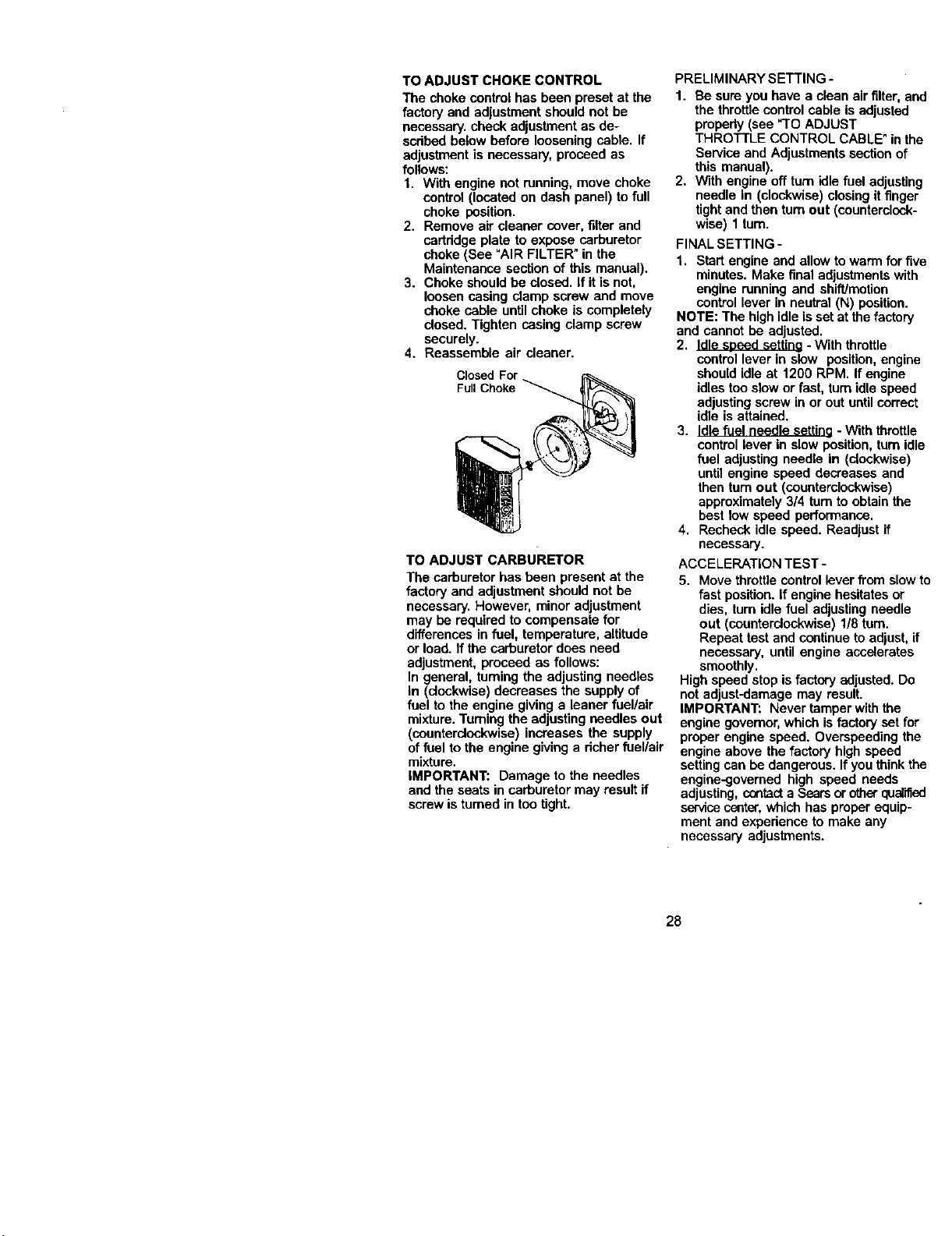
TO ADJUST ATTACHMENT LIFT
SPRING
1. While holding spdng bushing with
wrench, loosen jam nut.
• Turn adjustment holt clockwise to
extend spdng and reduce lifteffort for
heavier attachments.
• Turn adjustment holt eountemlockwise
for lighter attachments.
2. Retighten jam nut against spdng
bushing.
IMPORTANT: Do not edjust for maximum
spdng tension when using light attach-
ments suchas a mower. Adjust liftlever
springto aid in liftingattachment. Do not
overpower spdng. When removing
attachment, always adjust spring tension
to its lowest position.
Adjustment Bolt Spring
HeadlightWire
Connector
ENGINE
Maintenance, repair, or replacement of
the emission control devicesand sys-
tems, which are being done at the
customers expense, may be performed
by any non-reed engine repair establish-
ment or individual.Warranty repairs must
be performed by an authorized engine
manufacturer's service outlet.
TO ADJUST THROTTLE CONTROL
CABLE
The throttle controlhas been preset at the
factory and adjustment should not be
necessary. Check adjustment as de-
scdbed below before looseningcable. If
adjustment is necessary, proceed as
follows:
1. With engine not running, move throttle
control lever tofast position.
2. Check that speed control lever is
against stop screw. If itis not, loosen
casing clamp screw and pullthrottle
cable untillever is against screw.
Tighten clamp screw securely.
IdLespeed Adjusting
Throttle
Control
AttachmentLift
Jam Nut Spring
TO REMOVE HOOD AND GRILL
ASSEMBLY
1. Raise hood.
2. Unsnap headlight wire connector.
3. Stand in front oftractor. Grasp hood at
sides, tilttoward engine and lift off of
tractor.
4. To replace, reverse above procedure. 27
Stop
ClamF
Choke Control Cable
TO ADJUST CHOKE CONTROL
The choke control has been preset at the
factory and adjustment should not be
necessary, check adjustment as de-
scdbed below before loosening cable. If
adjustment is necessary, proceed as
follows:
1. With engine not running, move choke
control (located on dash panel) to full
choke position.
2. Remove air cleaner cover,filter and
cartddge plate to expose carburetor
choke (See "AIR FILTER" in the
Maintenance section of this manual).
3. Choke should be dosed. If it is not,
loosen casing clamp screw and move
choke cable untilchoke is completely
closed. Tighten casing clamp screw
securely.
4. Reassemble air cleaner.
Closed
Full Choke
TO ADJUST CARBURETOR
The carburetor has been present at the
factory and adjustment should not be
necessary. However, minor adjustment
may be required to compensate for
differences in fuel, temperature, altitude
or load. If the carburetor does need
adjustment, proceed as follows:
In general, turningthe adjusting needles
In (clockwise) decreases the supplyof
fuel to the engine givinga leaner fuel/air
mixture. Turning the adjusting needles out
(counterclockwise) increases the supply
of fuel to the engine giving a richer fuel/air
mixture.
IMPORTANT: Damage to the needles
and the seats in carburetor may result if
screwis turned in too tight.
PRELIMINARY SETTING -
1. Be sure you have a clean air filter, and
the throttlecontrol cable is adjusted
propedy(see "TO ADJUST
THROTTLE CONTROL CABLE" in the
Service and Adjustments section of
this manual).
2, With engine off turnidle fuel adjusting
needle In (clockwise) closingit finger
tight and then turnout (counterclcck-
wise) 1 tum.
FINAL SETTING -
1. Start engine and allowto warm for five
minutes. Make final adjustments with
engine running and shift/motion
control lever in neutral (N) position.
NOTE: The highidle is setat the factory
and cannot be adjusted.
2. Idle sneed setting - With throttle
controllever in slow position,engine
should idle at 1200 RPM. If engine
idles too slowor fast, turn idle speed
adjustingscrew in or out untilcorrect
idle is attained.
3. Idle fuel needle settine- With throttle
control lever in slow position, turnidle
fuel adjusting needle In (clockwise)
until engine speed decreases and
then turnout (counterclockwise)
approximately 3/4 turnto obtain the
best low speed performance.
4. Recheck idle speed. Readjust if
necessary.
ACCELERATION TEST -
5. Move throttlecontrol lever from slowto
fast position. If engine hesitates or
dies, turn idle fuel adjusting needle
out (counterclockwise) 1/8 turn.
Repeat test and continue to adjust, if
necessary, until engine accelerates
smoothly.
High speed stop is factory adjusted. Do
not adjust-damage may result.
IMPORTANT: Never tamper withthe
engine governor,which isfactory set for
proper engine speed. Overspeeding the
engine above the factory high speed
setting can be dangerous. If you think the
engine-govemed high speed needs
adjusting, contact a Searsor other qualified
servicecenter, which has proper equip-
ment and expedenca to make any
necessary adjustments.
28
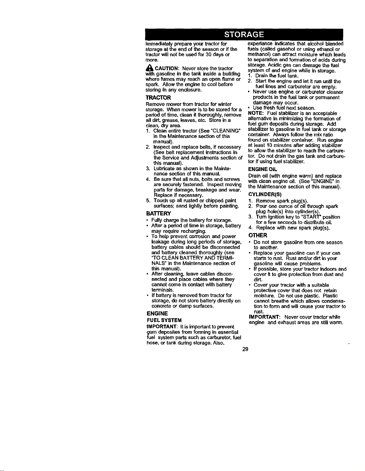
Immediately prepare your tractor for
storage at the end of the season or ifthe
tractorwill not be used for 30 days or
more.
_ CAUTION: Never store the tractor
with gasoline in the tank inside a building
where fumes may reach an open flame or
spark. Allow the engine to cool before
stodng in any enclosure.
TRACTOR
Remove mower from tractor for winter
storage. When mower isto be stored for a
pedod of time, clean itthoroughly, remove
all dirt, grease, leaves, etc. Store in a
clean, dry area.
1. Clean entire tractor (See "CLEANING"
in the Maintenance section of this
manual).
2. Inspect and replace belts, if necessary
(See belt replacement instructionsin
the Service and Adjusknents section of
this manual).
3. Lubdcata as shown in the Mainte-
nance section of this manual.
4. Be sure that all nuts, bolts and screws
are securelyfastened. Inspect moving
partsfor damage, breakage and wear.
Replace if necessary.
5. Touch up all rusted or chipped paint
surfaces; sand lightly before painting.
BA'n'ERY
• Fullycharge the batteryfor storage.
• After a peded of time in storage, battery
may require recharging.
• To help prevent corrosion and power
leakage dudng long pedods of storage,
battery cables should be disconnected
and battery cleaned thoroughly (see
=TOCLEAN BATTERY AND TERMI-
NALS" in the Maintenance section of
this manual),
• After cleaning, leave cables discon-
nected and place sables where they
cannot come in contact with battery
terminals.
• Ifbattery is removed from tractor for
storage, do not store battery directly on
concrete or damp surfaces.
ENGINE
FUELSYSTEM
IMPORTANT: It isimportantto prevent
gum deposites from forming in essential
fuel system parts such as carburetor, fuel
hose, or tank duringstorage. Also,
expedance indicates that alcohol blended
fuels (called gasobel or using ethanol or
methanol) can attract moisturewhich leads
to separation and formation of acids during
storage. Acidic gas can damage the fuel
system of and engine while in storage,
1. Drain the fuel tank.
2. Start the engine and let it run untilthe
fuel lines and carburetor are empty.
• Never use engine or carburetor cleaner
products in the fuel tank or permanent
damage may occur.
• Use fresh fuel next season.
NOTE: Fuel stabilizer isan acceptable
alternative in minimizingthe formation of
fuel gum deposits dudng storage. Add
stabilizerto gasoline in fuel tank or storage
container. Always follow the mix ratio
found on stabilizer container. Run engine
at least 10 minutes after adding stabilizer
to allow the stabilizer to reach the carbure-
tor. Do not drain the gas tank and carbure-
tor if using fuel stabilizer.
ENGINE OIL
Drain oil (with engine warm) and replace
with clean engine oil. (See "ENGINE" in
the Maintenance section of this manual).
CYLINDER(S)
1. Remove spark plug(s).
2. Pour one ounce of oil through spark
plug hole(s) into cylinder(s).
3. Tum ignitionkey to "START" position
for a few seconds todistdbute oil.
4, Replace with new spark plug(s).
OTHER
• Do not store gasolinefrom one season
to another.
• Replace your gasoline can if your can
startsto rust. Rustand/or dirtin your
gasoline will cause problems.
• If possible, store your tractor indoors and
cover itto give protactionfrom dustand
dirt.
• Cover your tractor with a suitable
protective cover that does not retain
moisture. Do not use plastic. Plastic
cannot breathe which allows condensa-
tionto form and will cause your tractorto
rust.
IMPORTANT: Never cover tractor while
engine and exhaust areas are stillwarm.
29
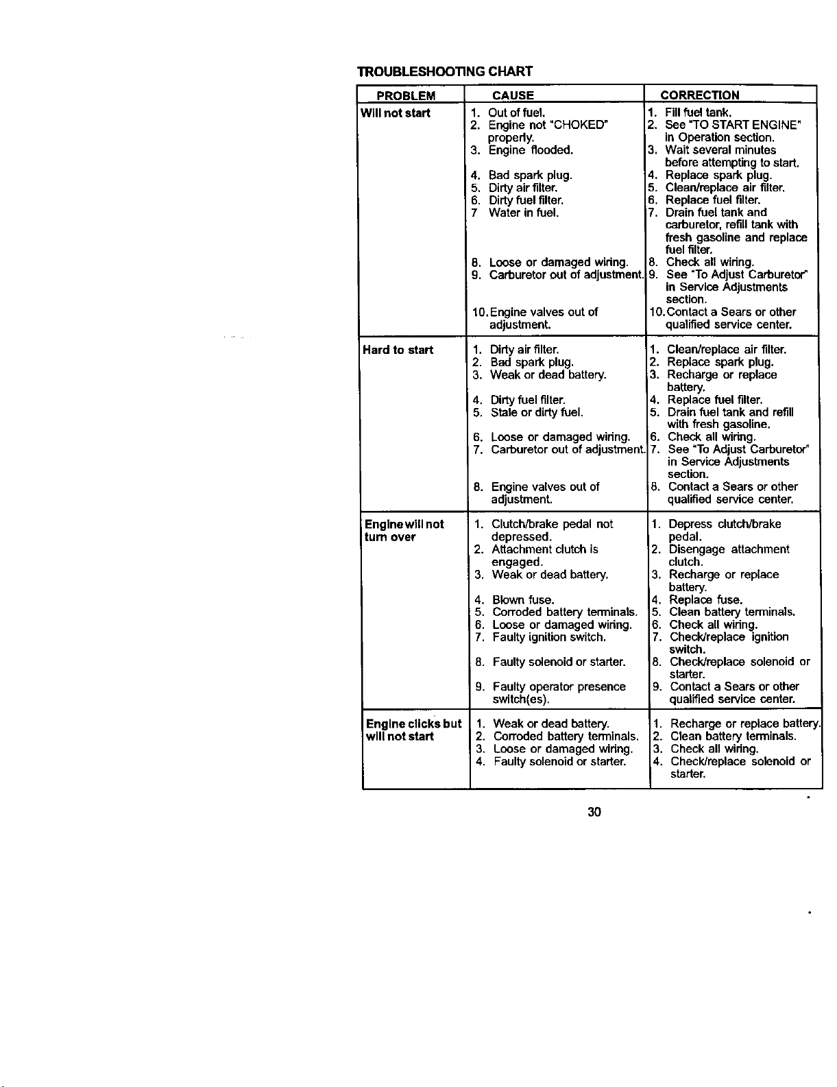
TROUBLESHOOTINGCHART
PROBLEM
Will not start 1.
2.
3.
4.
5,
6.
7
8.
9.
Hard to start
Engine wtil not
turn over
Engine clicks but
will not start
CAUSE
Out of fuel.
Engine not "CHOKED"
properly.
Engine flooded.
Bad spark plug.
Dirty air filter.
Dirty fuel filter.
Water in fuel.
Loose or damaged widng.
Carburetor out of adjustment.
10. Engine valves out of
adjustment.
1. Dirty air filter.
2. Bad spark plug.
3. Weak or dead battery.
4, Dirtyfuel filter.
5. Stale or dirtyfuel.
6. Loose or damaged widng.
7. Carburetor out of adjustment
8. Engine valves out of
adjustment.
1. Clutch/brake pedal not
depressed.
2. Attachment clutch is
engaged.
3. Weak or dead battery.
4. Blown fuse.
5. Corroded battery terminals.
6. Loose or damaged widng.
7. Faulty ignition switch.
8. Faulty solenoid or starter.
9. Faulty operator presence
switch(es).
1. Weak or dead battery.
2. Corroded battery terminals.
3. Loose or damaged widng.
4. Faulty solenoid or starter.
CORRECTION
1. Fill fuel tank.
2. See =TOSTART ENGINE"
in Operation section.
3. Wait several minutes
beforeattempting to start,
4. Replace spark plug.
5. Clean/replace air filter,
6. Replace fuel filter,
7. Drain fuel tank and
carburetor, refilltank with
fresh gasoline and replace
fuel filter.
8. Check all widng.
9. See "ToAdjust Carburetor"
in Service Adjustments
section.
10.Contact a Sears or other
qualified service center.
1. Clean/replace air filter.
2. Replace spark plug.
3. Recharge or replace
battery.
4. Replace fuel filter.
5. Drain fuel tank and refill
with fresh gasoline.
6. Check all widng.
7. See "To Adjust Carburetor"
in Service Adjustments
section.
B. Contact a Sears or other
qualified service center.
1. Depress clutch/brake
pedal.
2. Disengage attachment
clutch.
3. Recharge or replace
battery.
4. Replace fuse.
5. Clean battery terminals.
6. Check all widng.
7. CheckJraplace ignition
switch.
8. Check/replace solenoid or
starter.
9, Contact a Sears or other
qualified service center.
1. Recharge or replace battery
2. Clean battery terminals.
3. Check all widng.
4. Checldreplace solenoid or
starter.
30
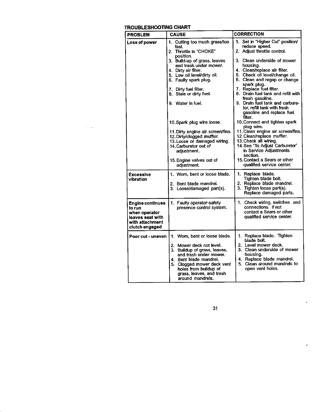
ROUBLESHOO'I1NG CHART
PROBLEM CAUSE CORRECTION
Loss of power 1. Cuffing toomuch grass/too
iExcessive
vibration
Engine continues
to run
when operator
leaves seat with
with attachment
clutch engaged
Poorcut-uneven
fast.
2. Throttle in "CHOKE"
position.
3. Build-upof grass, leaves
and trash under mower.
4. Dirtyair filter.
5. Low oil level/dirty oil.
6. Faultyspark plug.
7. Dirtyfuel filter.
8. Stale or dirtyfuel.
9. Water infuel.
10.Spark plug wire loose.
11. Dirty engine air screen/fins.
12. Dirty/clogged muffler.
13.Loose or damaged wiring.
14.Carburetor out of
adjustment.
15. Engine valves outof
adjustment.
1. Worn, bent or loose blade.
2. Bent blade mandrel.
3. Loose/damaged part(s).
1. Faultyoperator-safety
presence control system.
1. Worn, bent or loose blade.
2. Mower deck not level.
3, Buildupof grass, leaves,
and trash under mower.
4. Bent blade mandrel.
5. Clogged mower deck vent
holes from buildup of
grass, leaves, and trash
around mandrels.
1. Set in "Higher Cut" position/
reduce speed.
2. Adjust throttlecontrol.
3. Clean underside of mower
housing.
4. Clean/replace air filter.
5. Check oil level/change oil.
6. Clean and regap or change
spark plug.
7. Replace fuel filter.
8. Drain fuel tank and refillwith
fresh gasoline.
9. Drain fuel tank and carbure-
tor,refilltank withfresh
gasoline and replace fuel
filter.
10.Connect and tighten spark
plug wire.
11. Clean engine air scraen/fins,
12.Clean/replace muffler.
13.Check all wiring.
14.Sea "To Adjust Carburetor"
in Service Adjustments
section.
15.Contect a Sears or other
qualified service center.
I. Replace blade.
Tighten blade bolt.
2. Replace blade mandrel.
3. Tighten loose part(s).
Replace damaged parts.
1, Check wiring, switches and
connections. If not
contact a Sears or other
qualified service center.
1. Replace blade. Tighten
blade bolt.
2. Level mower deck.
3, Clean underside of mower
housing.
4. Replace blade mandrel.
5. Clean around mandrels to
open vent holes.
31
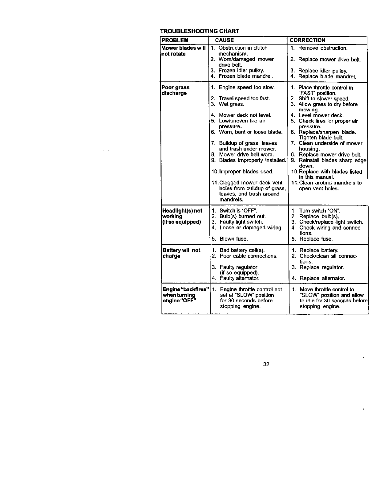
TROUBLESHOOTING CHART
PROBLEM CAUSE CORRECTION
Mowerbladeswill 1. Obstruction in clutch 1. Remove obstruction.
not rotate mechanism.
2. Worn/damaged mower I 2. Replace mower ddve holt.
drive belt.
3. Frozen idler pulley. 3. Replace idler pulley.
4. Frozen blade mandrel. 4. Replace blade mandrel.
Poor grass 1. Engine speed too slow.
discharge
Headlight(s) not
Norklng
[If so equipped)
2. Travel speed too fast.
3. Wet grass.
4. Mower deck not level.
_5. Low/uneven tire air
pressure.
6. Worn, bent or loose blade.
7. Buildupof grass, leaves
and trash under mower.
8. Mower ddve belt worn.
9. Blades improperly installed.
10.Improper blades used.
11. Clogged mower deck vent
holes from buildupof grass,
leaves, and trash around
mandrels.
1. Switch is=OFF".
2. Bulb(s) homed out.
3. Faulty lightswitch.
4. Loose or damaged wiring.
5. Blown fuse.
Battery will not 1.
charge 2.
3.
4.
Englna"hockflres" 1.
when turning
engine"OFF"
Bad battery cell(s).
Poor cable connections.
1. Place throttle control in
"FAST"position.
2. Shift to slower speed.
3. Allow grass todry before
mowing.
4. Level mower deck.
5, Check tires for proper air
pressure.
6. Replace/sharpen blade.
Tighten blade bolt.
7. Clean underside of mower
housing.
8. Replace mower ddve belt.
9. Reinstall blades sharp edg_
down.
10. Replace with blades listed
in this manual.
11,Clean around mandrels to
open vent holes.
1. Turnswitch"ON".
2. Replace bulb(s).
3. Check/replace light switch.
4. Check wiring and connec-
tions.
5. Replace fuse.
1. Replace battery.
2. Check/clean all connec-
tions.
Faulty regulator 3. Replace regulator.
(if so equipped).
Faulty alternator. 4. Replace alternator.
Engine throttlecontrol not 1. Move throttle controlto
set at "SLOW" position "SLOW" position and allow
for 30 seconds before to idle for 30 seconds beforq
stopping engine, stopping engine.
32
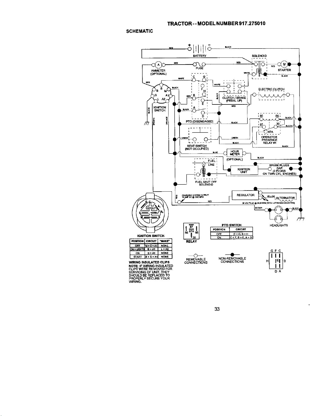
SCHEMATIC
TRACTOR -- MODEL NUMBER 917.275010
I
AMMETER
v*_r_
(
IGNITION SWITCH
WIRING INSULATED CUPS
NOTE: tF WIRING INSULATED
CUPS WERE REMOVED FOR
SERVtCING OF UNIT, THEY
SHOULD BE REPLACED TO
PROPERLY SECURE YOUR
WIRING.
i
• i
FUEL SHUT OFF
SOLENOID
RELAY
CLUTCH I BRAKE L ........
(PEDAL UP)
q85 861
b i 30I
OP_ CPRRR!RATOR
PRESENCE
m_c< LAy #1 S_CK
SPARK PLUGS
IGNmON , GAP
UNIT . PLUGS
PTO SWITCH
POSITION ORC_
ON C÷F, 8+ErA* D
OFF C÷GIB÷H
PJEGULATOR_
H_LIGHTS
REMOVABLE
CONNECTIONS
NON-REMOVABLE
CONNECTIONS
GFC
OA
33
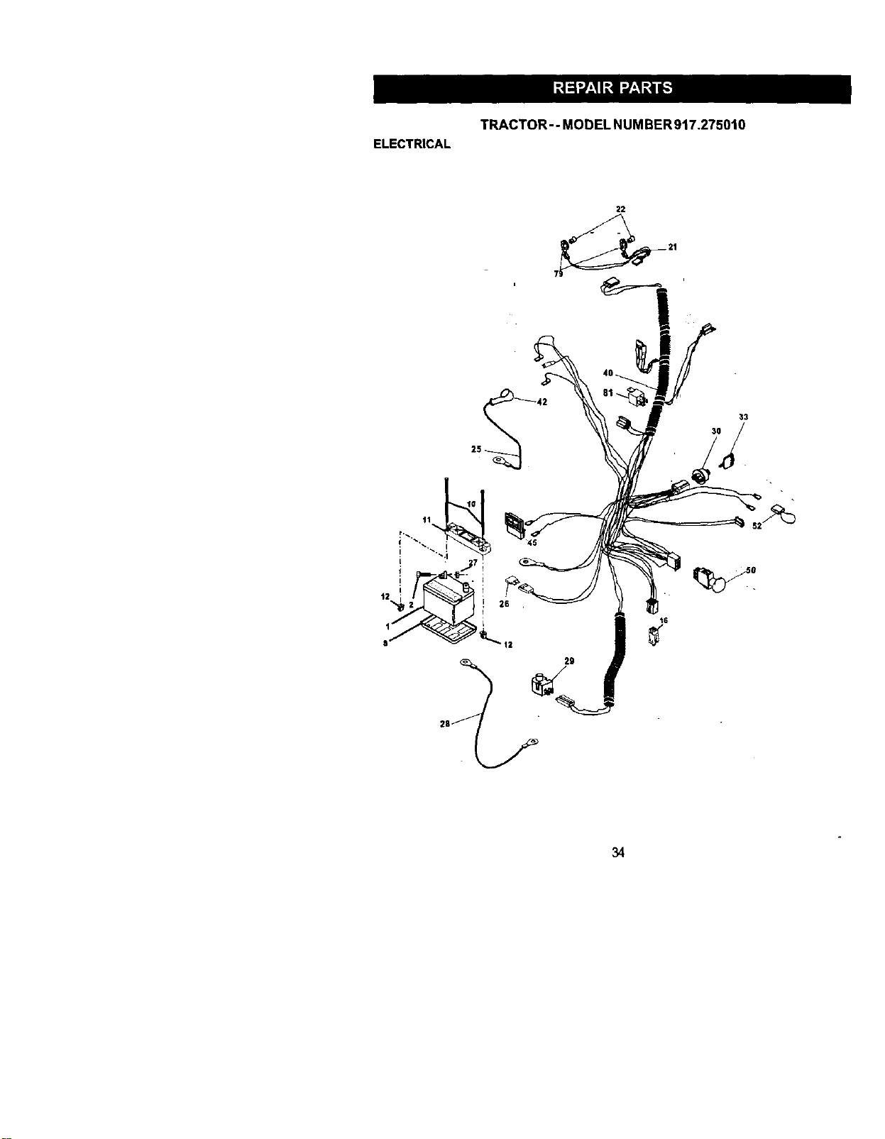
ELECTRICAL
TRACTOR-- MODEL NUMBER917.275010
29
16
34

TRACTOR -- MODEL NUMBER 917.275010
ELECTRICAL
KEY pART
NO. NO. DESCRIPTION
1 144927 Battery
2 74760412 Bolt Hex Head 1/4-20 x 3/4
8 7603J Tray, Battery
10 145211 Bclt 114-20 x 7.5 Zinc
11 150109 Hold down Battery Dash Mount
12 145769 Nut Push Nylon 114"
16 153664 Switch Interlock Push-In
21 136184 Hamess Socket LightWI4152J
22 4152J Bulb Light
25 150775 Cable, Battery
136824X Fuse
27 73510400 Nut Keps Hex t/4-20 Une
28 170697 Cable, Ground
29 160784 Switch, Plunger
30 175566 Switch, Ign
33 140403 Key, Lgni_on
40 170238 Harness Ign.
42 154336 Cover, Terminal
45 122822X Ammeter
50 174652 Switch, PTO
52 141940 protection Wire Loop
79 163996 Bulbholder Asm. incan descent
81 109748X Relay Asm.
NOTE: All component dimensions given In U.S, inches
1 inch = 25.4 rnm
35
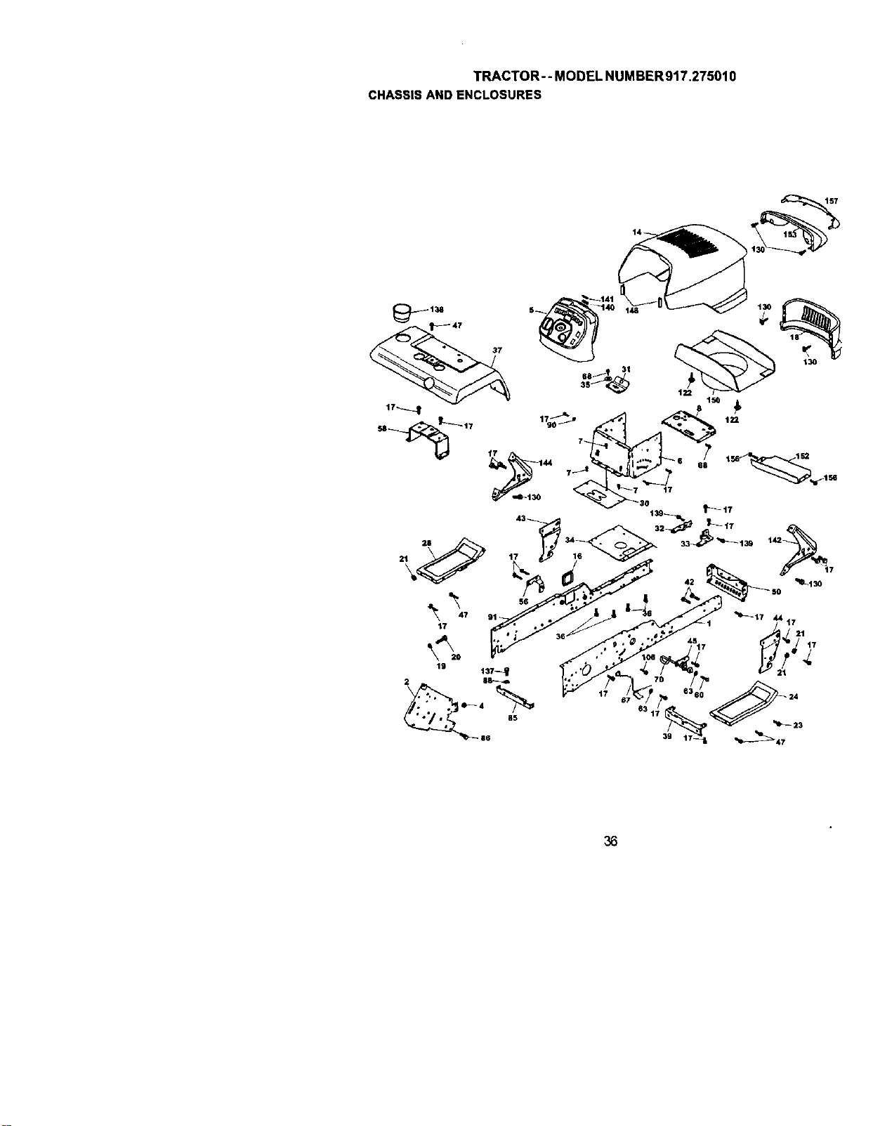
TRACTOR--MODELNUMBER917.275010
CHASSISANDENCLOSURES
,o
2 17
7
42 '_4L130
36
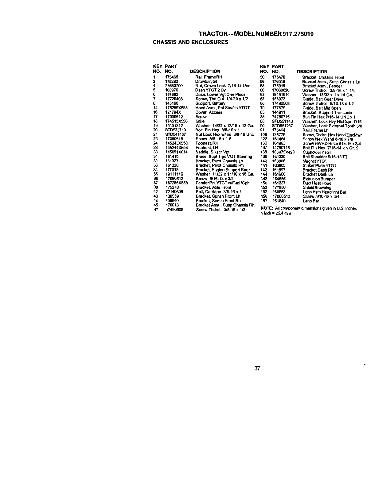
TRACTOR--MODELNUMBER917.275010
CHASSISANDENCLOSURES
KEY PART
NO. NO.
1 175465
2 175282
4 7368O7OO
5 163976
6 157882
7 17720408
8 145166
14 175259)(558
16 121794X
17 17000612
18 174515X558
19 19131312
20 STD5__3710
21 STD541437
23 17OO0616
24 145243X558
28 145244X558
30 145051)(014
31 161419
32 161327
33 161326
34 177018
35 19111116
36 17060512
37 167286X556
39 175276
42 72140608
43 136939
44 136940
45 176018
47 17490608
KEY PART
DESCRIPTION NO. NO. DESCRIPTION
Rail, Fran_ RH 50 175476 Bracket, Chassis Front
Drav/oar, Gt 56 176016 Bracket Asrn., Susp Chassis Lh
Nut, Crown Lock 7/16-14 Unc 58 175315 Bracket Asrn., Fender
Dash "(I"GT 2 Cyl 60 17060620 Screw Thdrol. 3/8-16 x 1-1/4
Dash, Lower Vgt One Piece 63 19131614 Washer 13132 x 1 x 14 Ga.
Screw, Thd Cut 1/4-20 x 1/2 67 156973 Guide, Belt Gear Drive
Support, Battery 68 17490508 Screw ThdrcL 5116-18 x 1/2
Hood Asrn., Pnt Stealth VrGT 70 177679 Guide, Belt Mid Span
Cover, Access 85 144911 Bracket, Support Transaxle
Screw 86 74760716 BoltFin Hex 7116-14 UNC x 1
Grille 88 STD551143 Washer, Lock Hvy Hlcl Spr 7/16
Washer 13/32 x 13/16 x 12 Ga. 90 STD551237 Washer, LockExternal Tooth 3/8
Bolt, Fin Hex 3/8-16 x 1 91 175464 Rail, Frame Lh
NutLockHexwllns 3/8-16Unc 106 138776 SPJew,ThdrolHexHeadZLncMwr
Screw 3/8-t6 x 1.5 122 161464 Screw Hex Wshd 8-18 x 7/8
Fo_rast, RH 136 164863 Scl_w HWHD Hi-Lo #13.16 x 3/4
Footrest, LH 137 74780716 Bo6FinHex 7/16-14x1Gr. 5
Saddle, Slkscr Vgt 138 163975)(428 CuphelderYTGT
Brace, Supt 1-po VGT Steering 139 161330 Bolt Shoulder 5/16-18 TT
Bracket, Pivot Chassis Lh 140 163806 MagnetYTGT
Bracket, Pivot Chassis Rh 141 163805 Sl_ikerPlute YTGT
Bracket, Engine Support Rear 142 161897 Bracket DaSh Rh
Washer 11132 x 11/16 x 16 Ca. 144 161900 Bracket Dash Lh
Screw _16-18 x 314 146 164655 Exl_uslonBumper
Fer_ler POt YTGT w/FUel/Cph 150 161237 Duct Heat Hood
Bracket, Axle Front 152 177956 ShieldBrowning
Bolt, Dardage 3/8-16 x 1 153 160568 LensAsrn Headlight Bar
Bracket, Spnsn Front Lh 156 17060612 Screw 5116-18 x 3/4
Bracket, Spnsn Front Rh 157 101840 LensBar
Bracket Asrn., Suup Chassis Rh
Screw Thdrdl. 3/8-16 x 1/2 NOTE: _1 component dirner_ons given in U.S. Inches
1 inch = 25.4 rnnrn
37
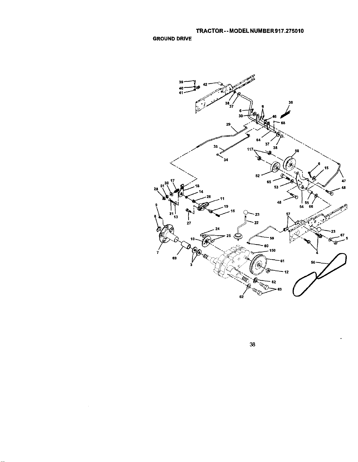
TRACTOR--MODELNUMBER917.275010
GROUNDDRIVE
39
36
37 6
64 _
34
5130 17 "718
28 14
9 , 19
27 _ 22
48
57
15
47
69
4
62
38
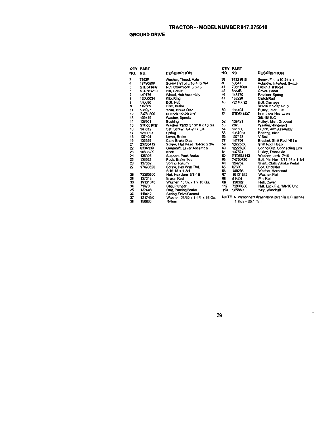
TRACTOR--MODELNUMBER917.275010
GROUNDDRIVE
KEY pART KEY PART
NO. NO, DESCRIPTION NO. NO. DESCRIPTION
3 7563R Washer, Thrust, Axle 39 74321016 Screw, Fin. #10-24 x 1
4 17490508 Screw Thdrol 5/16-18 x 314 40 5304.1 Actuator, Lntedeck Switch
5 S]O541437 NUt, Crownlock 3/6-16 41 73661000 LocknLIt #10-24
6 STD561210 Pin, Cotter 42 8883R Cover, pedal
7 149176 Wheet, Hub Assembly 46 145170 Retainer,Spring
8 12000034 Klip, Ring 47 138228 ClutchRod
9 140080 Bolt,Hub 48 72110612 Bolt,Carriage
10 142509 Disc, Brake 3/8-16 x 1-1/2 Gr. 5
11 136927 Yoke, Brake Disc 50 131494 Pulley, Idler, Flat
12 73750800 Nult_ck 1/2-20 Unf 51 STD541437 NUt, Lock Hex wllns.
13 139419 Washer, Special 3/6-t6UNC
14 138901 BL_hlng 5_ 139123 Pulley, Idler, Grooved
15 S/D551037 Washer 13/32 x 13/16 x 15 Ga. 53 207J Washer, Hardened
16 143012 Set, Screw 1/4-28 x 3/4 54 161590 Clutch, Arm Assernbly
17 126909X Spring 55 105706X Bearing, Idler
18 137104 Lever, Brake 56 137153 V-Belt
19 136926 Cam, Brake Disc 57 141756 Bracket, Shift Rod, HI-Lo
21 23260412 Screw, Flat Head 114-28 x 3/4 59 122253)( Shift Rod, Hi-Lo
22 633A109 Ge_rshlft, Lever Assembly 60 122268X Bpd ngCnp, connecting Link
23 106932X Knob 61 137524 Pulley, Trar_saxle
24 136925 Buppod, Puck Brake 62 BTD551143 Washer, LOck 7/16
25 136923 PUCk, Brake TOp 63 74760720 Bolt, Fin Hex 7/16-14 x 1-1/4
26 137552 Spring, Ratum 64 154752 Bhalff, Clutch/Brake Pede_
27 17490529 Screw, Hex Wsh Thd. 65 67609 Bolt, Bhoulder
5/16-18 x 1-3/4 66 140296 Washer,Hardened
28 73350606 Nut, Hex Jam 3/8-16 67 19131312 Washer, Flat
29 137213 Brahe, Rod 68 5142H Pin,RUll
30 19131616 Washer 13/32 x 1 x 16 Ga. 69 136327 Hub,Cover
34 71673 Cap, Plunger 117 73900600 Nut, Lock Fig. 3/8-16 Unc
35 137648 Rod, Parking Brake 150 9858M1 Key, Woodruff
36 149412 Spring, Ddve Ground
37 121749X Washer 25132 x 1-1/4 x 16 Go, NOTE: All compoi_erddimensions given in U.S, inches
38 150035 Nyliner 1 inch = 25,4 mm
39
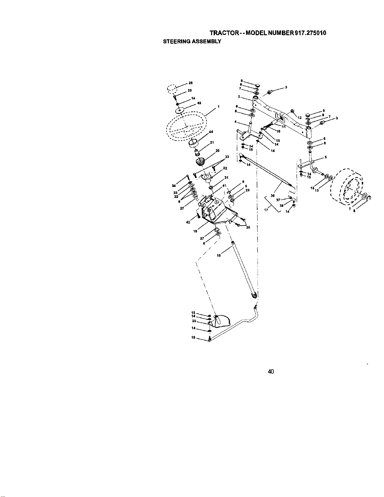
TRACTOR--MODELNUMBER917.275010
STEERINGASSEMBLY
3
/S
S'
13" / I / /_ ij !
13 I I _ .*,
40

TRACTOR--MODEL NUMBER917.275010
STEERINGASSEMBLY
KEY PART
NO. NO. DESCRIPTION
1 159ojI4Xd28 Wheel, Steering
2 137694 Axle Asm., Front
3 6855M Fitting, Grease
4 161849 SpindleAsm, LH
5 161848 Spindle Asm,, RH
6 6266H Be_dng, RaCe Thrust Harden
7 121748X Washer 25/32 x 1-5/_ x 16 Ga,
8 12(100029 Ring,KUp#T5304*75
9 121232X Cap, Splndal
10 74781044 B01t,Fin Hex 5/8-11 x 2-3/4
11 136518 Spacer Bearing Aale Front
12 73901000 Nut, Lock Flange 518-11 Unc
13 121749X Washer 25/32 x 1-114x 16 Ga.
14 STD551137 Washer, Lock I-h,y Hlol Spr 3/8
15 STD541537 Nut, Lock Center 3/8-24 UNF
16 145103 Shaft Asrn., Steering
17 137347 Rod Asm., Tie BallJ Bait Vgt (Inc. Key No. 36-10)
18 175572 Draglink, BallJoint Soiid Vgt
19 156011 Support Asrn., Steering Vgt
20 163887)(428 Boot, Steedng
21 159945 Adapter, Wheel Steeheg
22 155105 Bushing, Strg. Blk
23 1_2927 Screw
25 STD523710 Bolt, Fin Hex 315-16 x 1 Gr. 5
26 1_9948X428 Cap, Wheel Steering
27 3366R Beadng, Col. Strg.
28 17000612 _crew Hex Wsh Thdral 318-16
29 104239X Bearing,Flange
31 138136 Bushing, Nyliner Snap
32 19111610 Washer 11132 x 1 x 10 G_.
33 STD551131 Washer, Lock Hvy Hlcl Spr 5/16
34 STD523107 Bolt, Hex Hd 5116-18 x 3/4
35 138059 Gear, Sector Steering
36 137158 Tie Rad
37 73360600 JamNnt RH Thread
38 109850X Joint Asm, Ball RH Thread
39 73700600 Jam Nut LH Thread
40 109851X Joint Asm. BaLLLH Thread
41 155246 Bracket Switch Interiock VGT 97
42 17490508 Screw Thdral 5/16-18 x 1/2 Tyt
44 160135)(428 Extension, Steering
45 19132411 Washer 13132 x 1-lt20 x 11 Ga.
NOTE: All component dimensions given inU.S. inches
1 inch = 25.4 rnm
41
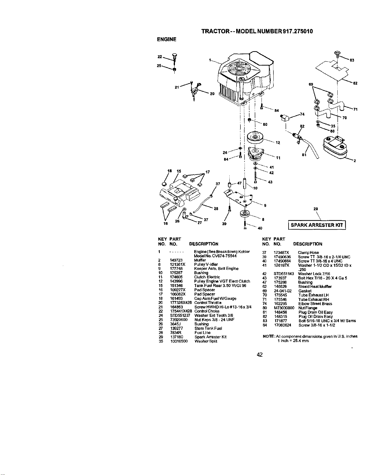
ENGINE
TRACTOR-- MODEL NUMBER917.275010
25
84
61
, 63
69 _62
t8 15 t7
26
. \
4O [SPARK ARRESTER KITJ
KEY PART KEY PART
NO. NO. DESCRIPTION NO. NO. DESCRIPTION
1 ...... Euglne (See Bre_zkdown)Kohler 37 123467X Clamp Hose
Model No. CV674-75544 39 17490636 Screw TT 3/8-16 x 2-1/4 UNC
2 149723 Muffler 40 17490664 Screw TT 3/8-16 x4 UNC
8 121361X Pulley V-Idler 41 126197X Washer 1-1/20D x 15/32 ID x
g 177748 Keeper Asm. Belt Engine .250
10 175287 Bushing 42 STD551143 Washer Lock7/16
11 174605 Clutch Electric 43 173937 Bad Hex 7/16 - 20 X 4 Ga 5
12 143996 Pulley Engine VGT Elect Clutch 47 175288 Bushing
15 151346 Tank Fuel Rear 3,50 Yt/Gt 96 62 146629 Shield Heat Muffler
16 10_27X pad Spacer 69 24_041_)2 Gasket
17 106082X pad Spacer 70 175545 Tube Exhaust LH
18 161493 Cap Asm FtJelW/Gauge 71 175546 Tuhe Exhaust RH
20 177328X428 ControlThrottle 74 162295 Elbow Street Brass
21 164863 Screw HWHD Hi-Lo #13-16 x 3/4 80 M73030800 Nut Flange
22 175441X428 ControIChoke 61 148456 Ping Drain Oil Easy
24 STD551237 Washer Ext Tooth 3/8 82 148315 Plug Oi1Drain Easy
25 73_0600 Nut Keps 3/8 - 24 UNF 83 171877 Bolt 5/16-18 UNC x 3/4 W/Sems
26 3645J Bushing 84 17060624 Screw 3/8-16 x 1-1/2
27 139277 Stem Tank Fuel
28 7834R Fuel Line
29 137180 Spark Attester Kit NOTE: All component dlmensior;s given in U,S. inches
35 10016500 Washer Spilt 1 inch = 25.4 turn
42
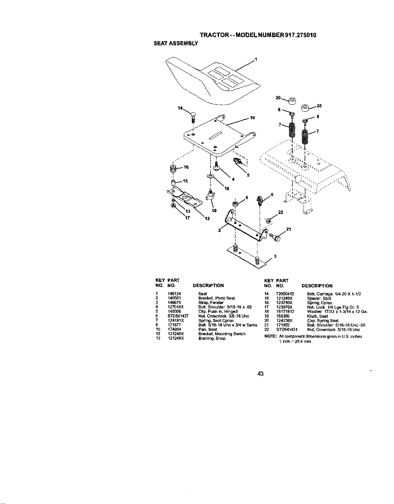
TRACTOR--MODELNUMBER917.275010
SEATASSEMBLY
KEY PART KEY PART
NO. NO. DESCRIPTION NO. NO. DESCRIPTION
1 140124 Seat 14 72050412
2 140951 Bracket, pivot Seat 15 121249X
3 140675 Strap,Fender 16 123740)(
4 127018X Sort, SheLilder 5116-18 X .62 17 123976X
5 145006 Clip, Push in, Hinged 18 19171912
6 STO541437 Nut, Crownlock 3/8-16 Uric 19 166369
7 124181X Spd r=g,Seat Cprsr_ 20 124238X
8 171877 Bolt 5/16-18 UnC x 3/4 w Seres 21 171852
10 174894 Pan, seat 22 $11To41431
12 121246X Bracket, Mounting Switch
13 121248X BuShing,Snap
BOlt,Carriage 114-20 X 1-1/2
Spacer, Sprit
Spdng, Cprsn
NUt, Lock 1/4 Lge Fig Gr. 5
Washer 17/32 x 1-3/16 x 12 Ga.
Knob, Seat
Cap, Spring Seat
SQIt, Shoulder 5116-18 Unc -2A
Nut, Crownlock 5/16-18 Urbc
NO_: All component dimensionsgiven tn U,S. Lnches
1 inch = 25.4 mm
43
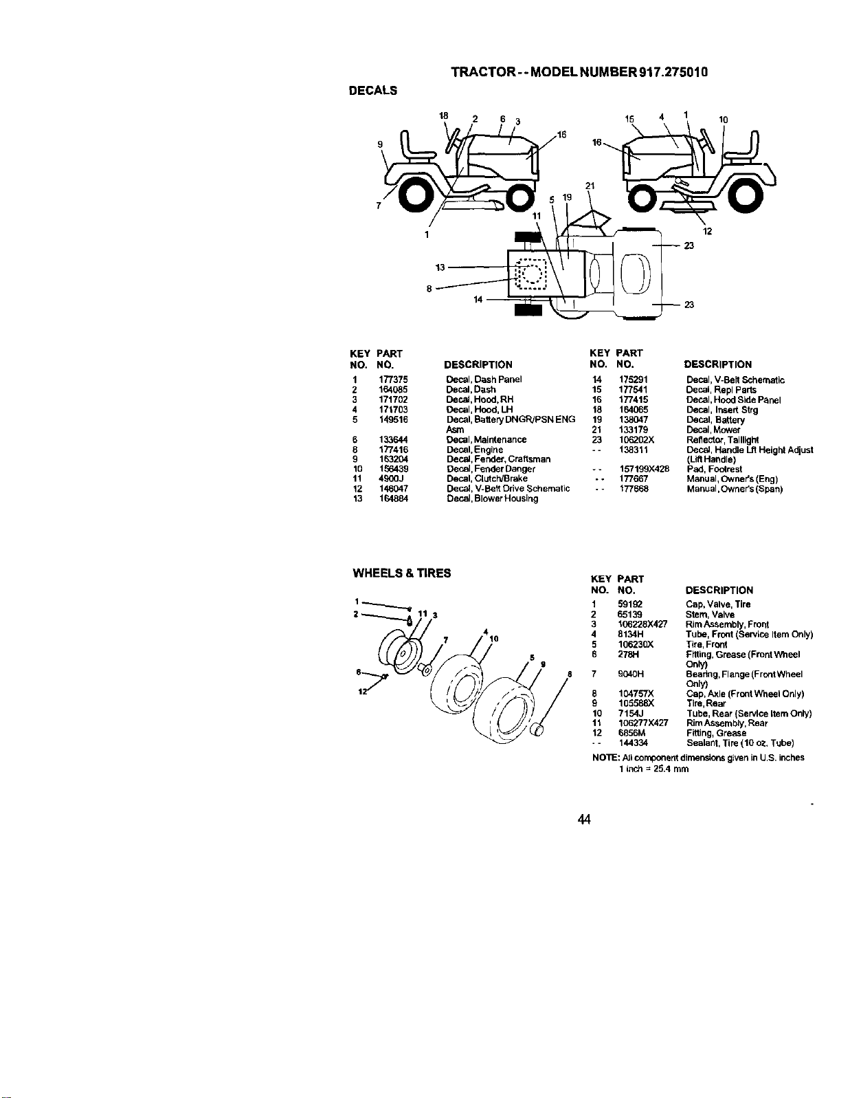
DECALS
TRACTOR-- MODEL NUMBER917.275010
18 2 6 3 15 4 1
16-_.
10
1
13
8
21
12
23
23
KEY PART
NO. NO.
1 177375
2 164085
3 171702
4 171703
5 149516
6 133644
8 177416
9 163204
10 156436
11 490(]J
12 146047
13 164884
KEY PART
DESCRIPTION NO. NO.
Decal, DBsh Panel 14 175291
Decal, Dash 15 177541
Decal, Hood,RH 16 177415
Decal, Hood, LH 18 164065
Decal, Battery DNGR/PSN ENG 16 138047
Asm 21 133179
Decal, Maintenance 23 10_02X
Decal,Engine - - 138311
Decal, Fender, Craftsman
Decal, Fender Danger -- 157199X428
Decal, Clutch/Brake - - 177667
Decal, V-Bert Drive Schematic - - 177668
Decal, Blower Housing
DESCRIPTION
Decal, V-Belt Schematic
Decal, Repl Parts
Decal, Hood Side Panel
Decal, Ir_sertStrg
Decal, Battery
Decal, Mower
Reflector, Taillight
Decal, Handle Lft Height Adjust
(LiftHandle)
pad, Footrest
Manual, Owner's (Eng)
Manual, Owner's (Span)
WHEELS&TIRES
4
10
KEY
NO.
1
2
3
4
5
6
8
9
10
11
12
PART
NO. DESCRIPTION
59192 Cap, Valve, Tire
65139 Stem, Valve
106228X427 Rim Assembly, Front
8134H Tube, Front (Service Item Only)
106230)( Tire, Front
2781-1 F_ing, Grease (Front Wheel
Only)
6040H Beadng, Flange (FrontWheel
Only)
104757)( Cap, Axle (Front Wheel Only)
105588)( Tire,Rear
7154J Tube, Rear (Service LtemOnly)
106277X427 RimAssembly, Rear
6856M Fitting,Grease
144334 Sealant, Tire (10 oz. Tube)
NO]_: AJlcomponent dimensionsgiven in IJ.S. inches
1 inch = 25.4 mm
44
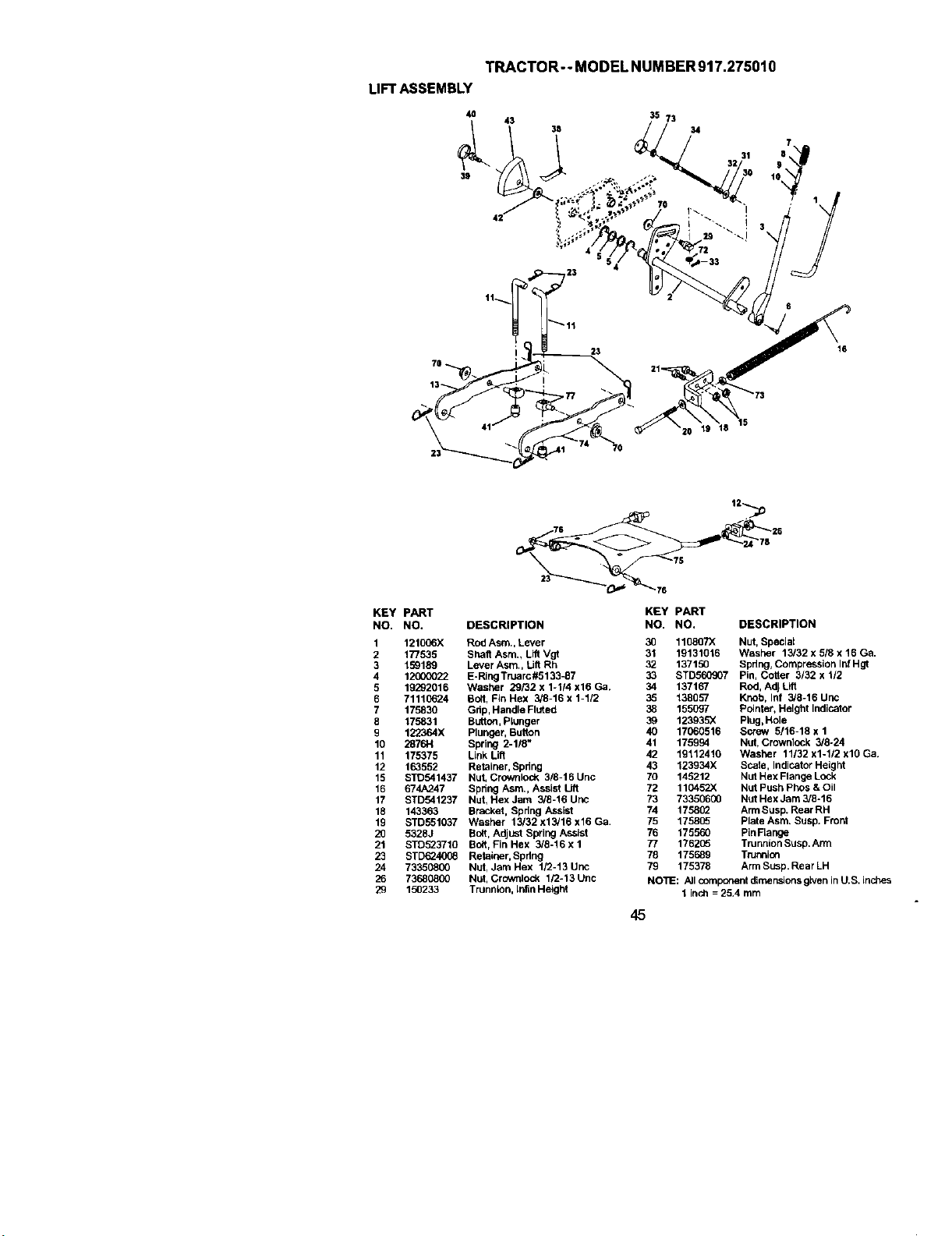
TRACTOR--MODELNUMBER917.275010
LIFTASSEMBLY
4O
39
35 73
34
16
7O
KEY PART
NO. NO,
1 121006X
2 177535
3 159189
4 12000022
5 19292016
6 71110624
7 175830
8 175831
g 122364X
10 2876H
11 175375
12 163552
15 STO541437
16 674A247
17 STD541237
18 143363
19 STD551037
20 53283
21 STD523710
23 SFD624008
24 73350800
26 73680800
29 150233
t,-7
76 f 26
24 78
DESCRIPTION
Rod Asm., Lever
Shaft Asm,, Lift Vgt
Lever Asm., Lift Rh
E-Ring Truarc#5133-87
Washer 29/32 x 1-1/4 x16 Ga.
Boit, Fin Hex 3/8-16 x 1-112
Grip, Handle Fluted
Button,Plunger
Plunger, Button
Spring 2-118_
Link Lift
Retainer, Spring
Nut, Crownlock 3/8-16 Unc
Spring Asm,, Assist Lift
Nut1Hex Jam 3/6-16 uric
Bracket, Spring Assist
Washer 13/32 x13/16 x16 Ga,
Bolt, Adjust Spring Assist
Bott, Fin Hex 3/8-16 x 1
RetaS_er, Spring
Nut, Jam Hex 1/2-13 Unc
Nut, Crowntock 1/3-13 Uric
Trunolon, [nflnHeight
KEY PART
NO. NO. DESCRIPTION
30 110807)( Nut, Speciat
31 19131016 Washer 13/32 x 5/8 x 16 Ga,
32 137150 Spdng, Compresslon InfHgt
33 STD560907 Pin, Cotter 3/32 x 1/2
34 137167 Rod, Adj Lift
35 138957 Knob, Inf 3/8-16 Uric
38 155097 Pointer, Height Indicator
39 123935)( Plug,Hole
40 17060516 Screw 5/16-18 x 1
41 175994 Nut, Crownlock 3/8-24
42 19112410 Washer 11/32 x1-1/2 xl0 Ga.
43 123934X Scale, Indicator Height
70 145212 Nut Hex Flange Lock
72 11045ZX Nut Push Phas & Oil
73 73350600 Nut Hex Jam 3/8-16
74 1758(_ Arm Susp. Rear RH
75 175805 plate Asm. Susp, Front
76 175560 Pin Flange
77 176205 TnJnnionSusp. Arm
78 175689 Trunnion
79 175376 Arm Susp.Rear LH
NOTE: ,6JIcomponent dimensionsg_venin U.S. inches
1 inch = 25.4 mm
45
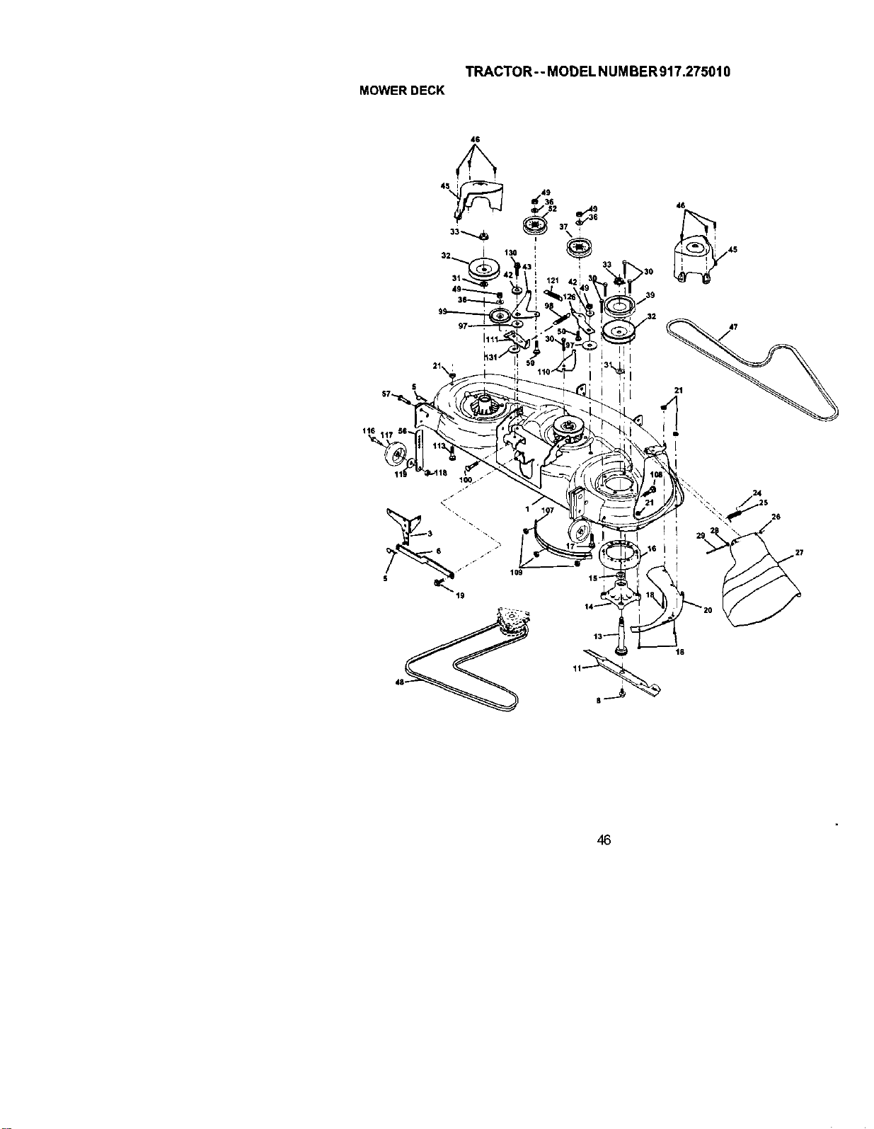
TRACTOR--MODELNUMBER917.275010
MOWERDECK
46
116
48
26
18
46
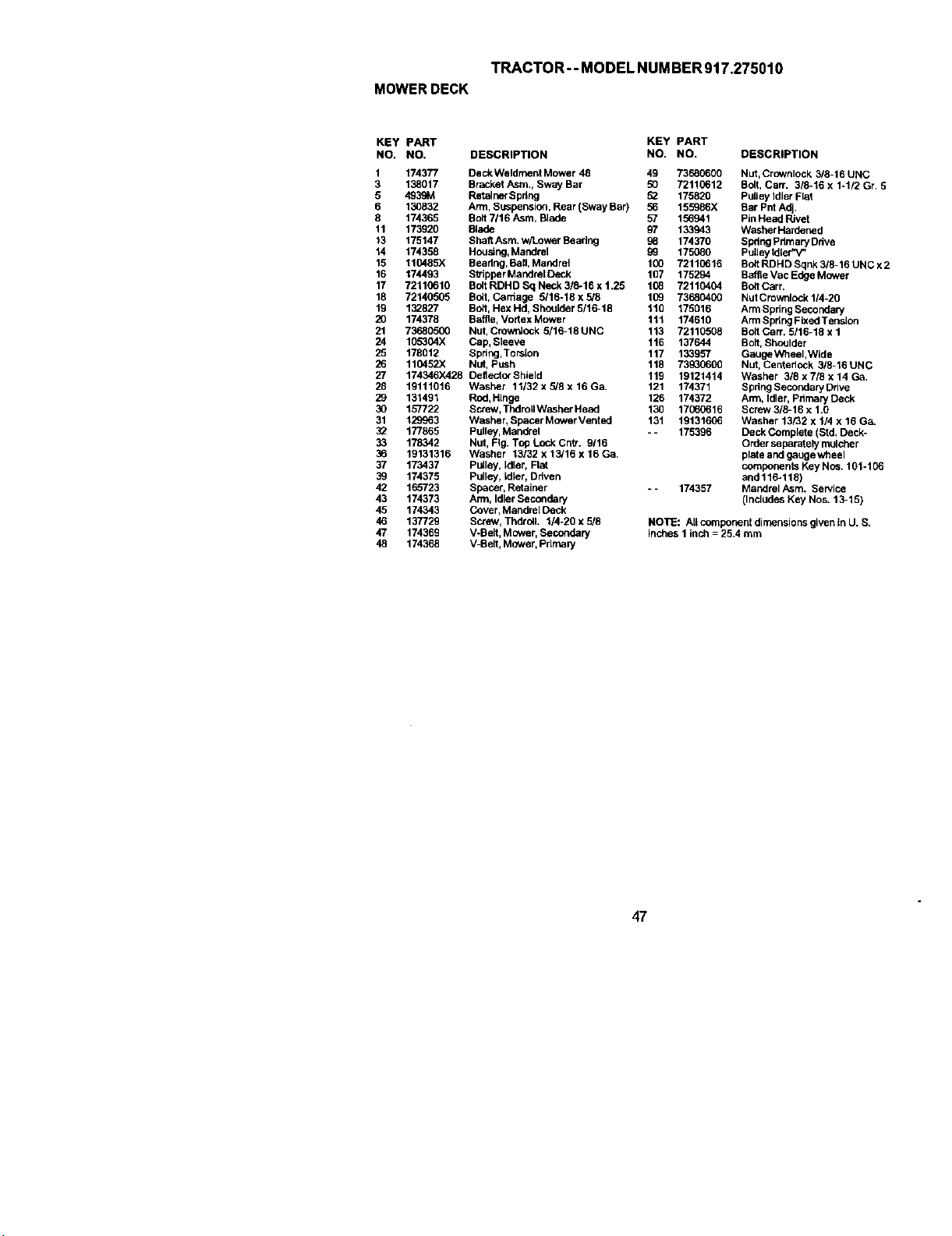
TRACTOR -- MODEL NUMBER 917.275010
MOWERDECK
KEY PART KEY PART
NO. NO. DESCRIPTION NO. NO. DESCRIPTION
1 174377 DeckWeldrnent Mower 48 49 73680600 Nut, Crownlock 3/8-16 UNC
3 138017 Bracket Asm., Swey Bar 50 72110612 Bolt, Carr. 3/8-16 x 1-1/3 Gr, 5
5 4939M Retainer Spring 52 175820 PulLeyidler Flat
6 130832 Arm, Suspension_ Rear (Sway Bar) 56 155986X Bar Pnt Adj,
8 174365 Bolt 7/16 hsm. Blade 57 156941 Pin Head Rivet
11 173920 Blade 97 133943 Washer Hardaned
'_3 175147 Shell Asm. W/LOWerBearing g8 174370 SpringPdmaryDdve
14 174358 Housing,Mandrel 9g 175080 Pulley IdLer%e
15 110485)( Beadng, Batl, Mandrol 100 72110616 Bolt RDHD Sqnk 3/8-16 UNC x 2
16 174493 Stripper Mandrel Deck 107 175294 BariteVac Edge Mower
17 72110610 Bolt RDHD Sq Neck 3/8-16 x 1.25 108 72110404 Bolt Cart.
18 72140505 Bolt, Carriage 5/16-18 x 5/8 109 73680400 Nut Crownlock 1/4-20
19 132827 Bolt, Hex Hd, Shcu_der 5/16-18 110 175016 Arm Spdng Secondaej
20 174378 Baffle, Vortex Mower 111 174610 ArmSpdng Fixed Tension
21 73680500 Nut, Crowntock 5/16-18 UNC 113 72110508 Bolt Con'. 5/16-18 x 1
24 105304X Cap, S_eeve 116 137644 Bolt, Shoulder
25 178012 Spring,Torsion 117 133957 GaugeWheeI,WLde
26 110452X Nut, Push 118 739_0600 Nut, Centerlock 3/8-16 UNC
27 174346)(428 Deilector Shulld 119 19121414 Washer 3/8 x 7/8 x 14 Ca,
28 19111016 Washer 11/32 x 5/8 x 16 Ga. 121 174371 SpringSecondaryDrive
29 131491 Rod_Hinge 126 174372 Arm, Idler, Primary Deck
30 157722 Screw_Thdrol_Washer Head 130 17060616 Screw 3/8-16 x 1.0
31 129963 Washer, SpacerMowerVented 131 19131606 Washer 13/32 x 1/4 x 16 Ga.
32 177865 Pulley, Mandrel - - 175396 Deck Complete (Std, Deck-
33 178342 Nut, Fqg.Top Lock Cntr. g/16 Order separately mulcher
36 19131316 Washer 13/32 x 13/16 x 16 Ga_ plate and geugewheel
37 173437 Pulley, Idler, Flat components Key Nos. 101-106
39 174375 Pulley, _dler, Driven and 116-118)
42 165723 spacer, Retainer _- 174357 Mandrel Asm. Service
43 174373 Arm, Idler Secondary (Includes Key Nos. 13-15)
45 174343 Cover, MandrelOeck
46 137729 Sctew_ Thdroll. 1/4-20 x 5/8 NOTE: AI_component dimensions given In U. S.
47 174369 V-Belt, Mower, Secondary Inches 1 inch = 25,4 mm
48 174368 V-Belt, Mower, Primary
47
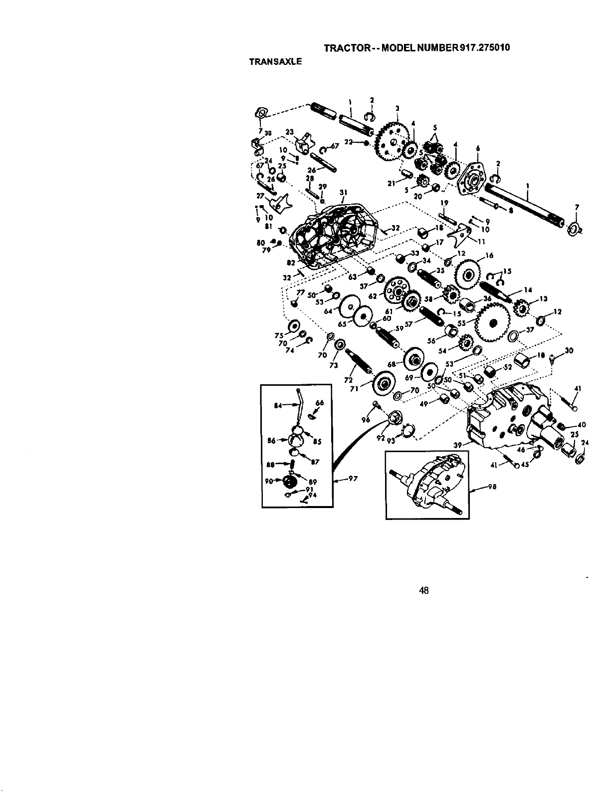
TRANSAXLE
TRACTOR-- MODEL NUMBER917.275010
| 2
6
2
73
72
48
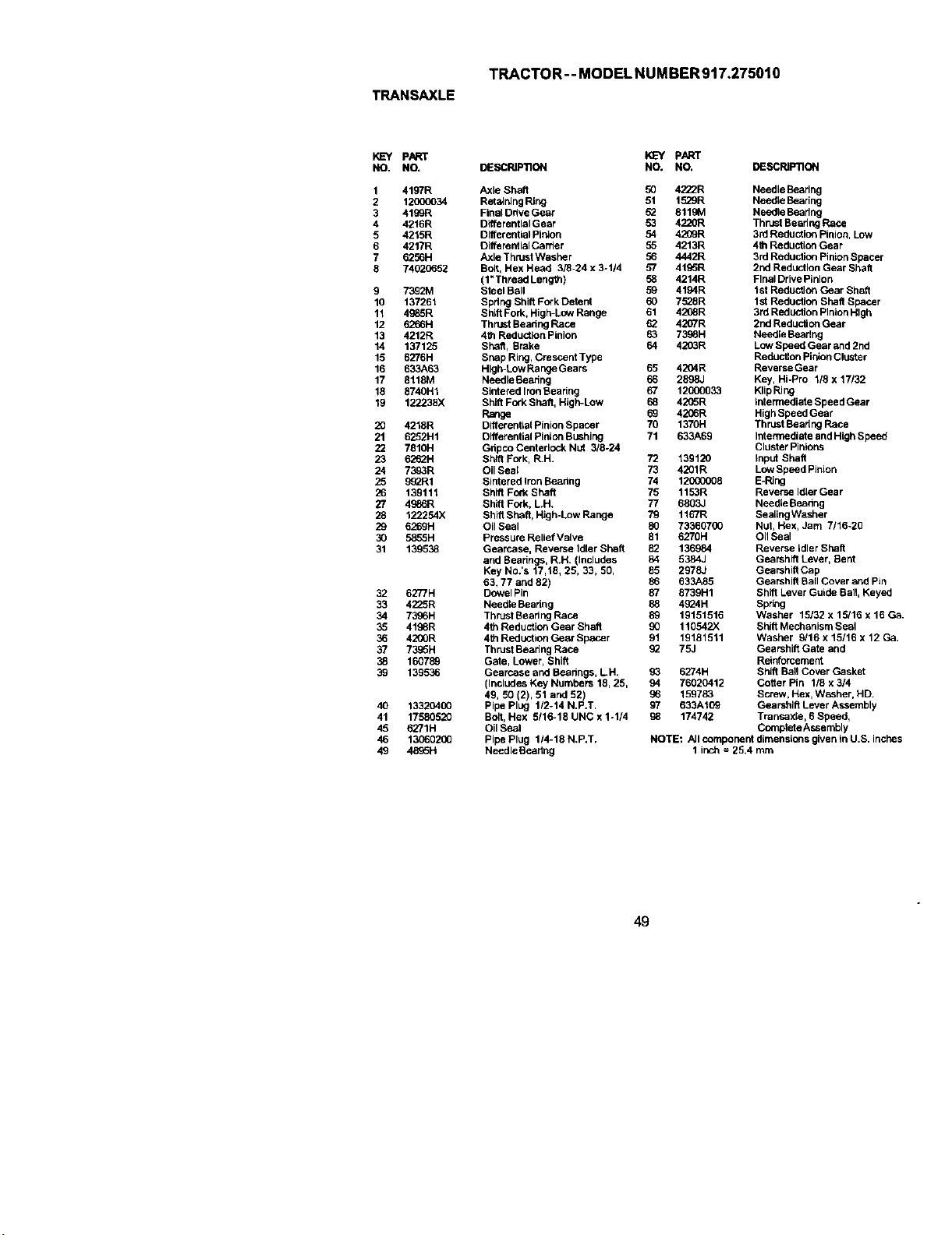
TRACTOR--MODELNUMBER917,275010
TRANSAXLE
KEY PART
NO. NO.
1 4197R
2 1200(_34
3 4199R
4 4216R
5 4215R
6 4217R
7 6288H
8 74020652
9 7392M
10 137261
11 4985R
12 6266H
13 4212R
14 137125
15 6276H
16 633A63
17 81181VI
18 8740H1
19 122238X
20 4218R
21 6252H1
22 7810H
23 6262H
24 7393R
25 88_R1
26 139111
27 4988R
28 122254X
29 6269H
30 5885H
31 139938
32 6277H
33 4225R
34 7388H
35 4198R
36 42_R
37 73_5H
38 160788
39 139936
40 13320400
41 17580920
49 6271H
46 13O6o2OO
49 4896H
_-Y pART
DESCRIP'nON NO. NO, DESCRIFI3ON
Axle Shaft 50 4222R
RetainingRing 91 1529R
Final Ddve Gear 52 9119M
Differential Gear 53 4;_0R
Differential Pialon 54 4209R
OiffereiffialCarder 55 4213R
Axle Thrust Washer 56 4442R
Bolt, Hex Head 3/6-24 x 3-1/4 57 4196R
(1"Thread Length) 58 4214R
Steel Ball 59 4194R
Spdng Shift Fork Detent 60 7528R
Shift Fork, High-Low Range 61 4208R
Thrust Bearing Race 62 4207R
4th Reduction Pinion 63 7388H
Shaft, Brake 64 42_R
Snap Ring, Crescent Type
High-Low Range Gears 65 4204R
Needle Beadng 66 2898J
SIntered Iron Bearing 67 12000033
Shift Fork Shaft, High-Low 68 4205R
Range 69 4206R
Differen6al Pinion Spacer 70 1370H
Differential Pinion Bushing 71 633A69
Gdpco Centerlock N_ 3/8-24
Shift Fork, R.H. 72 139120
OilSeal 73 4201R
Sintered Iron Beadeg 74 120(30008
Shift Fork Shaft 75 1153R
Shift Fork, LH. 77 6803J
Shift Shaft, High-Low Range 79 1167R
Oil Seal 80 73360700
Pressure Relief Valve 81 6270H
Gearcase, Reverse Idler shag 82 136984
and Bearings, R.H. (Includes 84 5384J
Key No.'s 17,18, 29, 33, 50, 85 29783
63, 77 and 82) 88 633A85
Dowel Pin 87 8739H1
Needle Beedng 88 49_4H
Thruat Bearing Race 89 19151516
4th Reduction Gear Shaft _() 110542X
4th Reduction Gear Spacer 91 19181511
Thrust Bearing Race _;_ 75J
Gate, Lower, Shift
Gearcase and Bearings, LH. 93 6274H
(Includes Key Numbers 18, 25, 94 76020412
49, 50 (2), 51 and 92) g6 159783
Pipe Plug 1/2-14 N,P.T. 97 633A109
Bolt, Hex 5116-18 UNC x 1-1/4 98 174742
OilSeal
Pipe Plug 114-18 N,P.T.
Needle Beedng
Needle Bearing
Needle Bearing
Needle Bearing
Thrust Bearing Race
3rdReduction Pinion, Low
4111Reduction Gear
3rd Reduclion Pinion Spacer
2nd Reduction Gear Sha6
FinalDrive Pinion
1st Reduction Gear Shaft
1st Reduction Shaft Spacer
3td Reduction Pinion High
2nd Reduction Gear
Needle Bearing
Low Speed Gear and 2nd
Reducgon PinionCluster
ReverseGear
Key, Hi-Pro 118 x 17/32
Klip Ring
intermediate Speed Gear
HighSpeed Gear
Thrust Beadng Race
Intermediate and High Speed
Cluster Pinions
input Shaft
LowSpeed Pinion
E-Ring
Reverse Idler Gear
Needle Beadng
Sealing Washer
Nut, Hex, Jam 7/16-20
Oil Seal
Reverse idler Shaft
Gearshift Lever, Sent
Gearshig Cap
Gearshift BallDover and Pin
Shift Lever Guide Ball, Keyed
Spring
Washer 15/32 x 15/16 x 16 Ga,
Shift Mechanism Seal
Washer 9/16 x 15/16 x 12 Ca.
Gearshift Gate and
Reinforcement
Shift Ball Cover Gasket
Coger Pin 1/8 x 3/4
Screw, Hex, Wesher, HD.
Gearshift Lever Assembly
Transax[e, 6 Speed,
Con_plateAssembly
NOTE: All component dimensions given in U.S. inches
1 inch = 25.4 mm
49
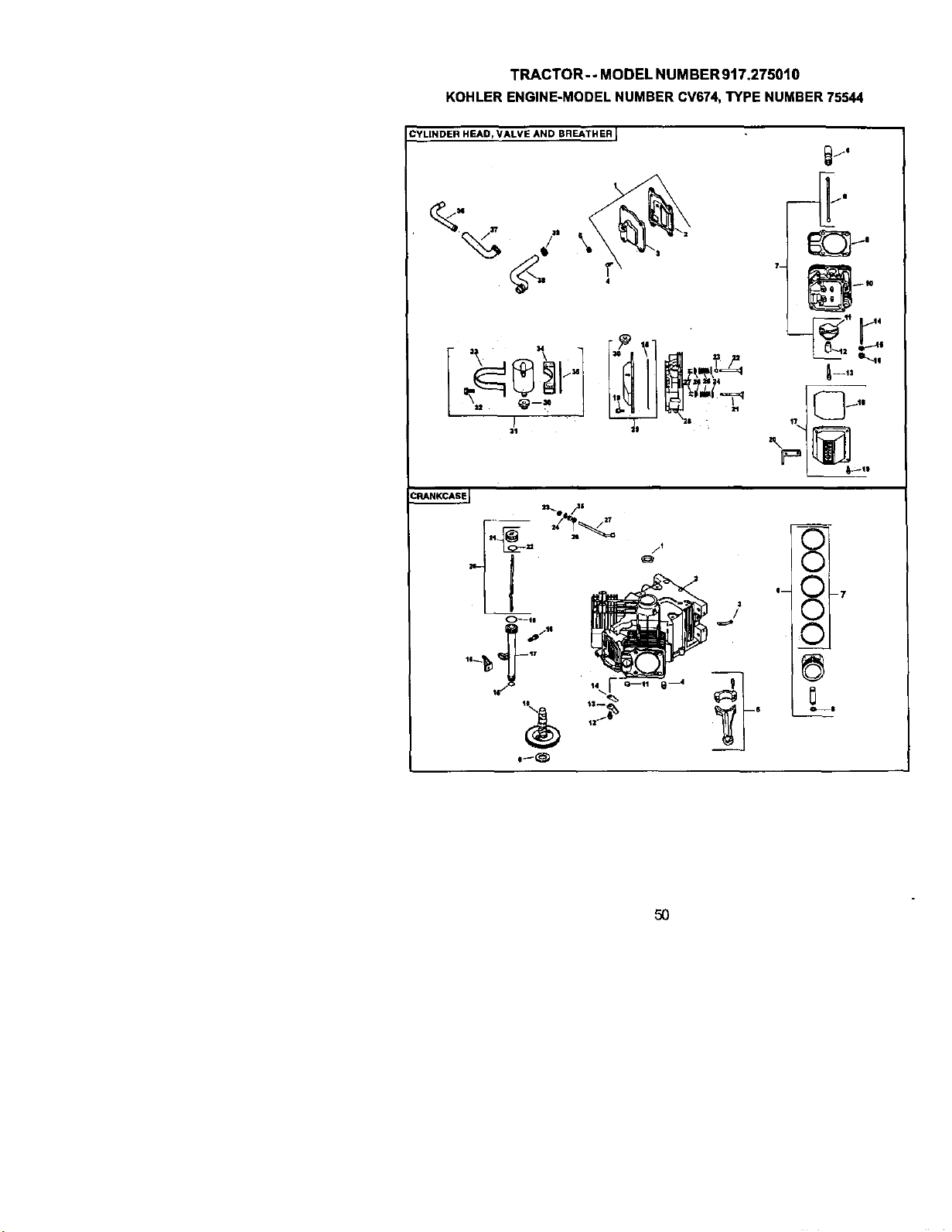
TRACTOR--MODELNUMBER917.275010
KOHLERENGINE-MODELNUMBERCV674,TYPENUMBER75544
CYLINDER HEAD, VALVE AND BREATHER L
:11
L 8_11
_E
50
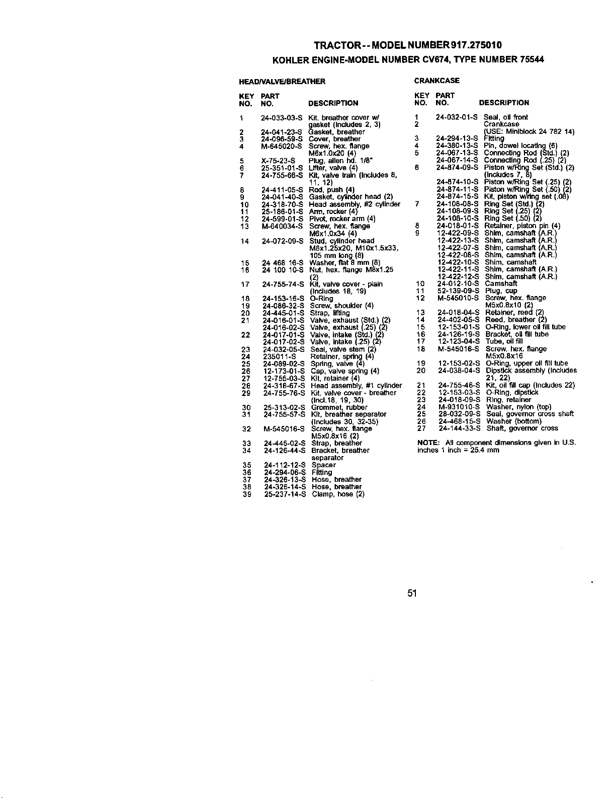
TRACTOR-- MODEL NUMBER917.275010
KOHLERENGINE-MODELNUMBERCV674,TYPENUMBER75544
HEADNALVE/BREATHER
CRANKCASE
KEY PART KEY PART
NO. NO. DESCRIPTION NO. NO. DESCRIPTION
1 24-033-03-S Kit, breather cover w/ 1 24-032-01-S
gasket (Includes 2, 3) 2
2 24-041-23-S Gasket, breather
3 24-096-59-S Cover, breather 3 24-294-13-S
4 M-645020-S Screw, hex. flange 4 24-360-13-S
M6x1.0x20 (4) 5 24-067-13-S
5 X-75-23-S Plug, allen hd. 1/8" 24-067-14-S
6 25-351-01-S Lifter, valve (4) 6 24-874-09-S
7 24-755-66-S Kit, valve train (Injuries 8,
11, 12) 24-874-10-S
8 24-411-05-S Rod, push (4) 24-874-11-S
9 24-041-40-S Gasket, cyttoder head (2) 24-874-15-S
10 24-316-70-S Head a_ssembly, #2 cylinder 7 24-108-08-S
11 25-186-01 -S Arm, rocker (4) 24-108-09-S
12 24-599-01-S Pivot. rocker arm (4) 24-108-10-S
13 M-640034-S Screw, hex. flange 8 24-018-01-S
M6x1.0x34 (4) 9 12-422-09-S
14 24-072-0g-s Stud, cylinder head 12-422-13-S
MSx1.25x20, M10x1.5x33, 12-422-07-S
105 mm long (8) 12-422-08-S
15 24 468 16-S Washer, fiat 8 mm (8) 12--422-10-S
16 24 100 10-S Nut, hex. flange M8X1.25 12-422-11-S
(;2) 12-422-12-S
17 24-755-74-S Kit. valve cover - p_aln 10 24-012-10-S
(Irmlude_ 18, 19) 11 52-139-09-S
18 24-153-16-S O-Ring 12 M-545010-S
19 24-086-32-S Screw, shoulder (4)
20 24-445-01-S Strap, lifting 13 24-018-04-S
21 24-016-01-S Valve, exhaust (Std.) (2) 14 24-402-05-S
24-016-02-S Valve, exhaust (.25) (2) 15 12-153-01-S
22 24-017-01-S Valve, intake (Std.) (2) 16 24-126-1g-s
24-017-02-S Valve, intake (.25) (2) 17 12-123-04-S
23 24-032-05-S Seal, valve stem 2 18 M-545016-S
24 235011-S Retainer, spdeg 4
25 24-089-02-S Spring, valve (4) 19 12-153-02-S
26 12-173-01-S Cap, valve spldng (4) 20 24-038-04-S
27 12-755-03-S Kg, retainer (4)
28 24-318-67-S Head assembly, #1 cylinder 21 24-755-46-S
29 24-755-76-S Kit, valve cover - breather 22 12-153-03-S
(thcl.18, 19, 30) 23 24-018_09-S
30 25-313-02-S Grommet, rubber 24 M-931010-S
31 24-755-57-S Kg, breather separator 25 28-032-09-S
(Includes 30, 32-35) 26 24-468-15-S
32 M-545016-S Screw, hex. flange 27 24-144-33-S
M5x0.8x16 (2)
33 24-445-02-S Strap, breather
34 24-126-44-S Bracket, breather
separator
35 24-112-12-S Spacer
36 24-294-06-S Flifthg
37 24-326-13-S Hose, breather
38 24-326-14-S Hose, breather
39 25-237-14-S Clamp, hose (2)
Seal, oil front
Crankcase
USE: Miniblock 24 782 14)
(_itting
Pin, dowel locating (6)
Connecting ROd (Std.) (2)
Connecting ROd (.25) (2)
Piston w/Rthg Set Std. 2
Includes 7,8)
Piston w/Ring Set (.25) (2)
Ptston w/Ring Set (.50)(2)
Kit, piston w/deg set (.08)
Ring Set (Std.) (2)
Ring Set (.25) (2)
Ring Set (.50) (2)
Retainer, piston pin (4)
Shim, camshaft (A.R.)
Shim, camshaft (A.R.)
Shim, camshaft (A.R.)
Shim, camshaft (A.R.)
Shim, camshaft
Shim, camshaft (A.R.)
Shim, camshaft (A.R.)
Camshaft
Plug, cup
Screw, hex. flange
M5x0.8xlO (2)
Retainer, reed (2)
Reed, breather (2)
O-Ring, lower oll fill tube
Bracket, oU fill tube
Tube, oil fill
Screw, hex. flange
M5x0.8x16
O-Ring, upper oll fill tube
Dipstick assembly (Includes
21, 22)
Kit, oil fill cap (Includes 22)
O-Ring, dipstick
Rlug, retainer
Washer, nylo_ (top)
Seal, governor cross shaft
Washer (bottom)
Shaft, governer cross
NOTE: PJI component dimensions given in U.S.
inches 1 inch = 25.4 mm
51
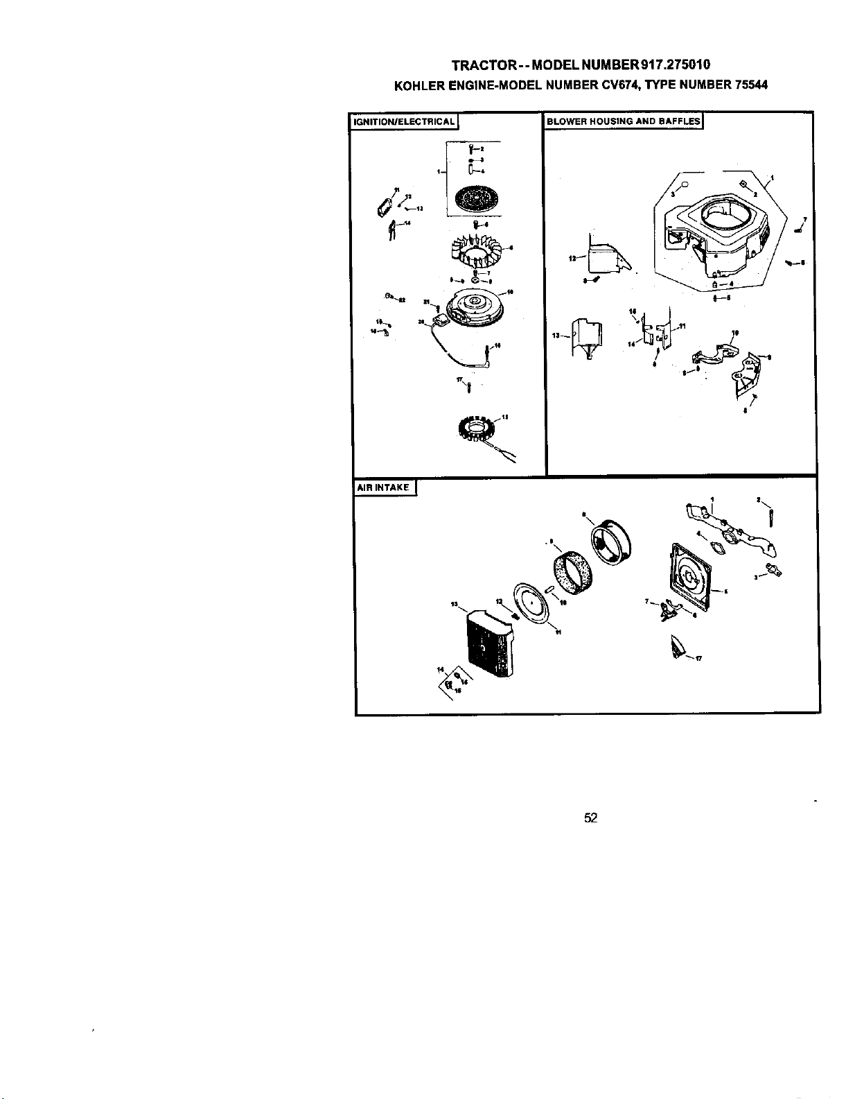
TRACTOR--MODELNUMBER917.275010
KOHLERENGINE-MODELNUMBERCV674,TYPENUMBER75544
IGNITION/ELECTRICAL I
IB--1
BLOWER HOUSING AND BAFFLES i
13__ 10
14
r?
|
AIR INTAKE_]
•e\
T_
_,tT
52
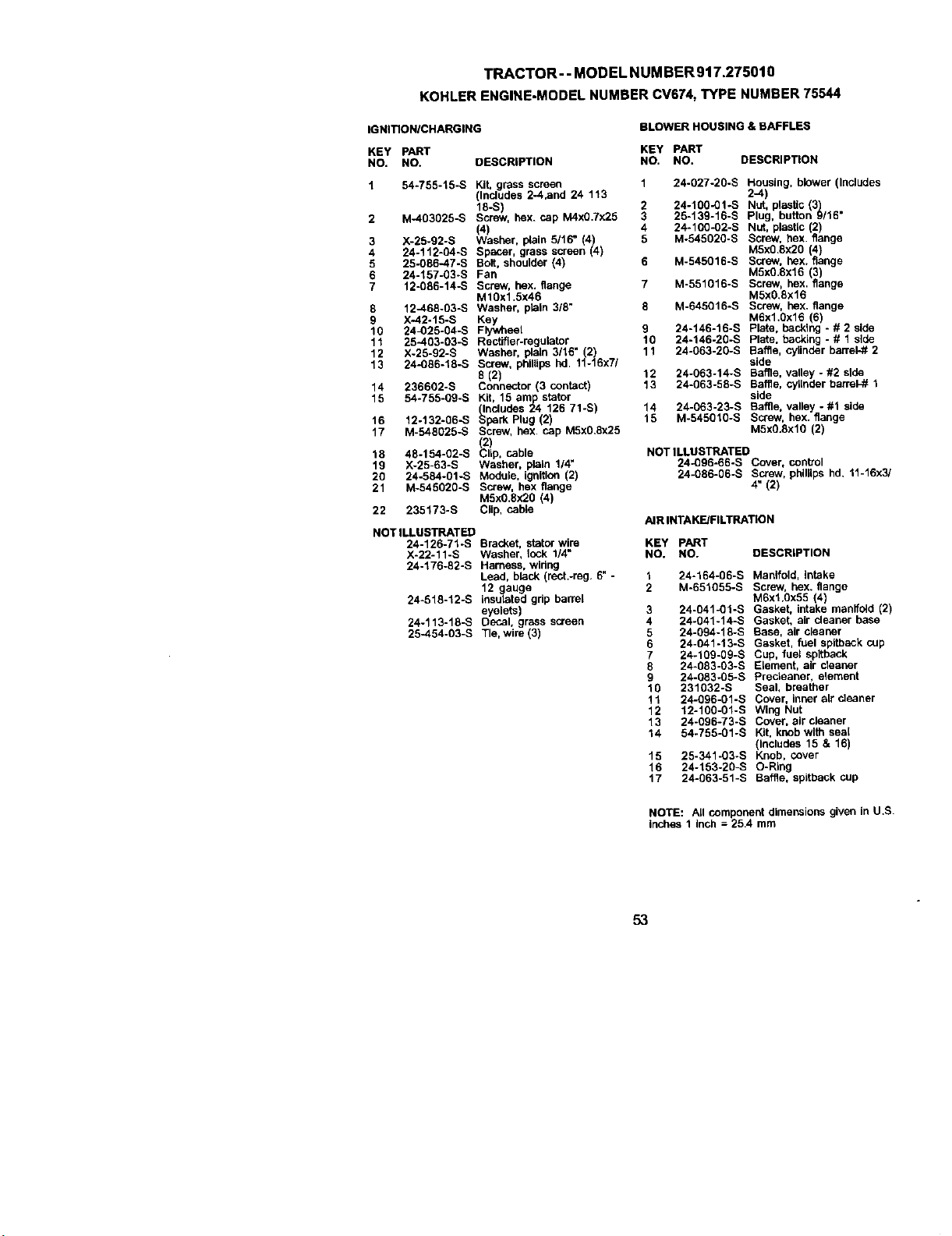
TRACTOR--MODELNUMBER917.275010
KOHLERENGINE-MODELNUMBERCV674,TYPENUMBER75544
IGNITIONICHARGING
BLOWER HOUSING & BAFFLES
KEY pART KEY PART
NO. NO. DESCRIPTION NO. NO. DESCRIPTION
1 54.755-15-S Kit, grass screen 1 24-027-20-S Housing, blower (Includes
(Includes 2-4.and 24 113 2--4)
18-S) 2 24-100-01-S Nut, ptasUc (3)
2 M-403025-S Screw, hex. cap M4xO.7x25 3 25-139-16-S Plug, button 9/16"
(4) 4 24-100-02-S Nut, plastic (2)
3 X-25-92-S Washer, plata 5116" 4) 5 M.545020-S Screw, hex. flange
4 24-112-04-S Spacer, grass screen (4 M5xg.Sx2O (4)
5 25-086-47-S Bolt, shoulder (4) 6 M-545016-S Screw, hex. flange
6 24-157-03-S Fan M5xO.8x16 (3)
7 12-086-14-S Screw, hex. flange 7 M-551016-S Screw, hex. flange
M10x1.5x46 M5xO.8x16
fl 12--468-03-S Washer, plain 3/6" 8 M-645016-S Screw, hex. flange
9 X.42-15-S Key M6x1.Ox16 6)
10 24_)25-04-S Fly_eet 9 24-146-16-S Plate, backing - # 2 sde
11 25-403-03-S Rectifier-regulator 10 24-146-2g-s Plate, backing - # 1 side
12 X-25-g2-s Washer, plain 3/16" (2) 11 24-063-20-S Baffle, cylinder barrel-# 2
13 24-086-18-S Screw, phillips hd. 11-16x7/ side
8 (2) 12 24-063-14-S Baffle, valley - #2 side
14 236602-S Connector (3 contact) 13 24-063-58-S Baffle, cylinder barrel_ 1
15 54.755-09-S Kit, 15 am stator side
(Includes 2P4 126 71-S) 14 24-063-23-S Baffle, valley - #1 side
16 12-132-06-S Spark Plug (2) 15 M-545010-S Screw, hex. flange
17 M-548025-S Screw, hex. cap M5x0.8x25 M5xO.8xl0 (2)
(2) cable
18 4fl-154-02-S Clip, NOT ILLUSTRATBD
19 X-25-63-S Washer, plain 1/4" 24-Qg6-66-S Cover, control
20 24-584-01-S Module, ignition (2) 24-086-06-S Screw, phillips hd, 11-16x3/
21 M-545020-S Screw, hex flange 4" (2)
M5x0.8x2O (4)
22 235173-S Clip, cable
AIR INTAKE/FILTRATION
NOT ILLUSTRATED
24-126-71.-S
X-22-11-S
24-176-82-S
Bracket, stator wire KEY PART
Washer, lock 1/4" NO. NO. DESCRIPTION
Harness, widng
Lead, black (rect.-reg. 6" - 1 24-164-06-S Manifold, intake
12 gauge 2 M-651055-S Screw, hex. flange
insulated grip barrel M6xt.Ox55 (4)
eyelets) 3 24-041_01-S Gasket, intake manifold (2)
Decal. grass screen 4 24-g41-14-S Gasket, air cleaner base
Tie, wire (3) 5 24-094-18-S Base, air cleaner
6 24-041-13-S Gasket, fuel spltback cup
7 24-109-09-S Cup, fuel spltback
8 24-083-03-S Elament, air cleaner
9 24-083-05-S Precleaner, element
10 231032-S Seal, breather
11 24-096-gl-S Cover, inner air cleaner
12 12-100-01-S Wing Nut
13 24-096-73-S Cover, air eleaner
14 54-755-01-S Kit, knob with seal
(Includes 15 & 16)
15 25-341-03-S Knob, cover
16 24-153-2g-s O-Ring
17 24-063-51-S Baffle, spitback cup
24-518-12-S
24-113-18-S
25-454-03-S
NOTE: All componentdimensionsgivenin U.S.
Inches 1 Inch = 25.4 mm
53
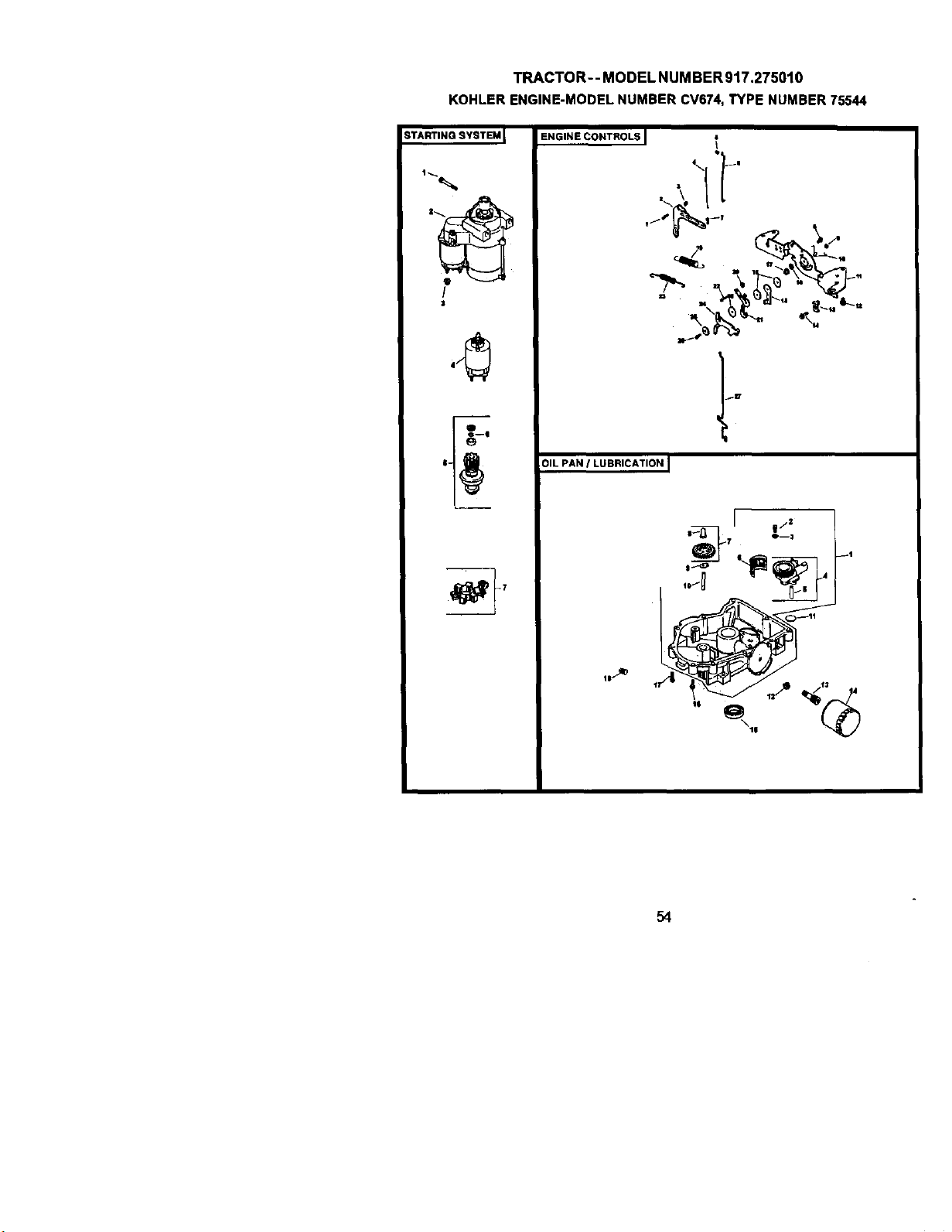
TRACTOR--MODELNUMBER917.275010
KOHLERENGINE-MODELNUMBERCV674,TYPENUMBER75544
STARTING SYSTEM_
!
$
ENGINE CONTROLS
Q_
jlT
OIL PAN I LUBRICATION I
)_ |/2
0--3
101_ 4
0--11
I 4
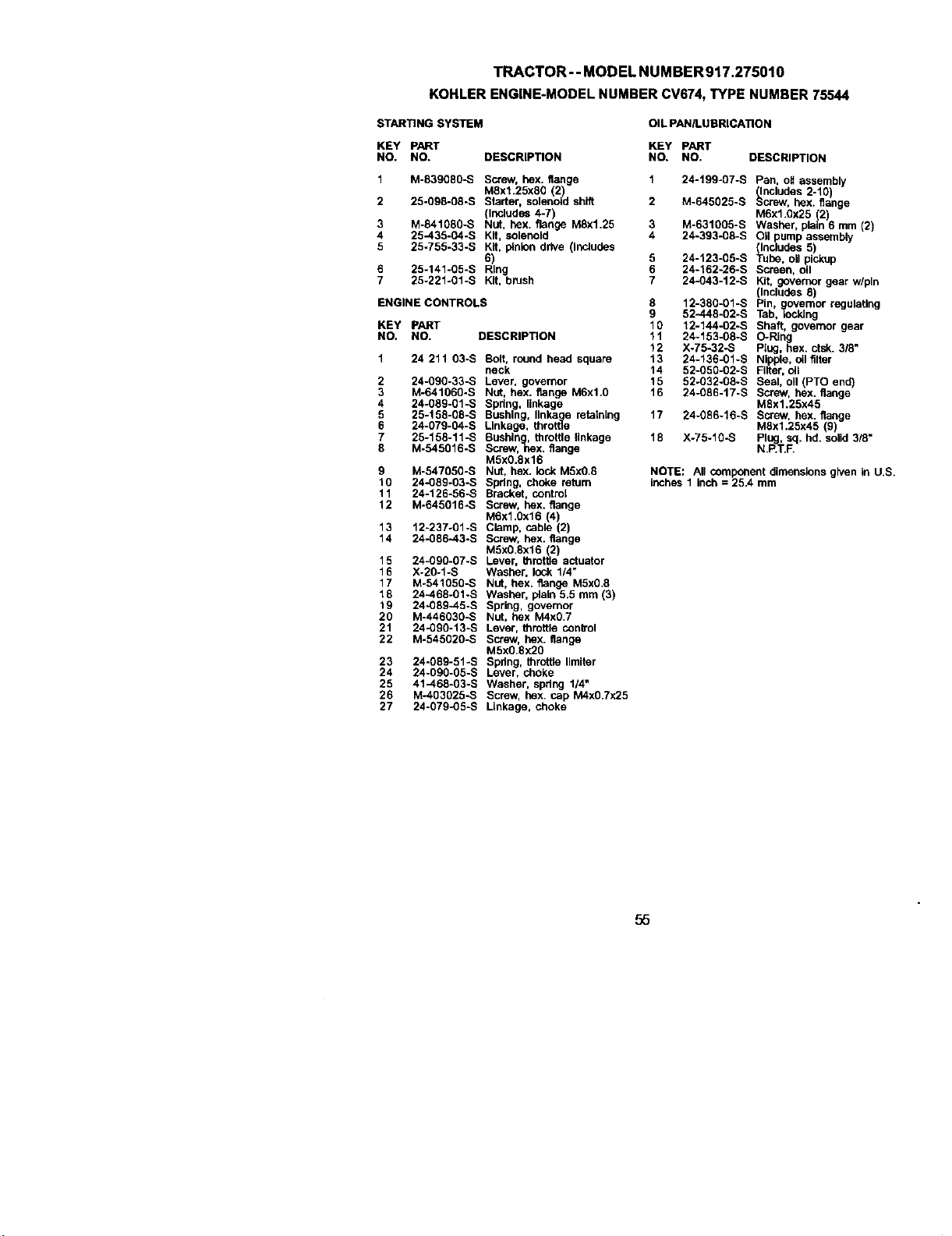
TRACTOR-- MODEL NUMBER917.275010
KOHLERENGINE-MODELNUMBERCV674,TYPENUMBER75544
STARTING SYSTEM OIL PAN/LUBRICATION
KEY PART KEY pART
NO. NO. DESCRIPTION NO. NO. DESCRIPTION
1 M-839080-S Screw, hex. flange
M8xl.25x80 2)
2 25-098-08-S S arter, so enoid shift
(Includes 4-7)
3 M-841080-S Nut, hex. flange M8x1.25
4 25-435-04-S Kit, solenoid
5 25-755-33-S 6l_t,_pinion drive (includes
6 25-141-g5-s Ring
7 25-221-gl-S Kit, brush
ENGINE CONTROLS
KEY PART
NO. NO. DESCRIPTION
2
3
4
5
6
7
8
24 211 03-S Bolt, round head square
neck
24-090-33-S Lever, governor
M-641060-S NUt, hex. flange M6xl.0
24-059-01-S Spring, linkage
25-158-08-S Bushing, linka e retathLng
24-079-04-S Linkage, thrott_
25-158-11-S Bushln , throttle linkage
M-545016-S Screw, ghex. flange
M5x0.8x16
M-547050-S Nut, hex. lock M5x0.8
24-08g-03-S Spdng, choke return
24-126-56-S Bracket, control
M-645016_S Screw, hex. flange
M6X1.0X16 (4)
12-237-01-S Clamp, cable (2)
24-086-43-S Screw, hex. flange
M5x0 8x16 (2)
24-0g0-07-S Lever, throttle actuator
X-20-1-S Washer, lock 1/4"
M-541050-S NUt, hex. flange M5X0.8
24-468-01-S Washer, plain 5.5 mm (3)
24-089-45-S Spring, governor
M-446030-S Nut, hex M4x0.7
24-090-13-S Lever, throttle conb'ol
M-545020-S Screw, hex. flange
M5x0.8x20
24-089-51-S Spring, throffie Ilmlter
24-09g-05-S Lever, choke
41-468-03-S Washer, spdeg 1/4"
M-403025-S Screw, hex cap M4x0.7x25
24-079-05-S Linkage, choke
9
10
11
12
13
14
15
16
17
18
19
20
21
22
23
24
25
26
27
1 24-199-07-S Pan, oil assembly
(Includes 2-10)
2 M-645025-S Screw, hex. flange
M6x1.Qx25 (2)
3 M-631005-S Washer, plain 6 mm (2)
4 24-393-08-S Oil pump assembly
(Includes 5)
5 24-123-05-S Tube, oil pickup
6 24-162-26-S Screen, oil
7 24-043-12-S Kit, governor gear w/pin
(Includes 8)
8 12-380-01-S Pin, gcovemor regulating
9 52-448-02.S Tab, iocldeg
10 12-144-02-S Shaft, governor gear
11 24-153-08-S O-Ring
12 X-75-32-S Plug, hex. ctsk. 3/8"
13 24-136-01-S Nipple, oil filter
14 52-050-02-S Filter, oil
15 52o032-08-S Seal, oll (PTO end)
16 24-086-17-S Screw, hex. flange
MSxl.25x45
17 24-086-16-S Screw, hex. flange
M8x1.25x45 (9)
18 X-75-10-S PI pUg._.,._q. hd. solid 318"
NOTE: All component dimensions given In U.S.
inches 1 inch = 25.4 mm
55
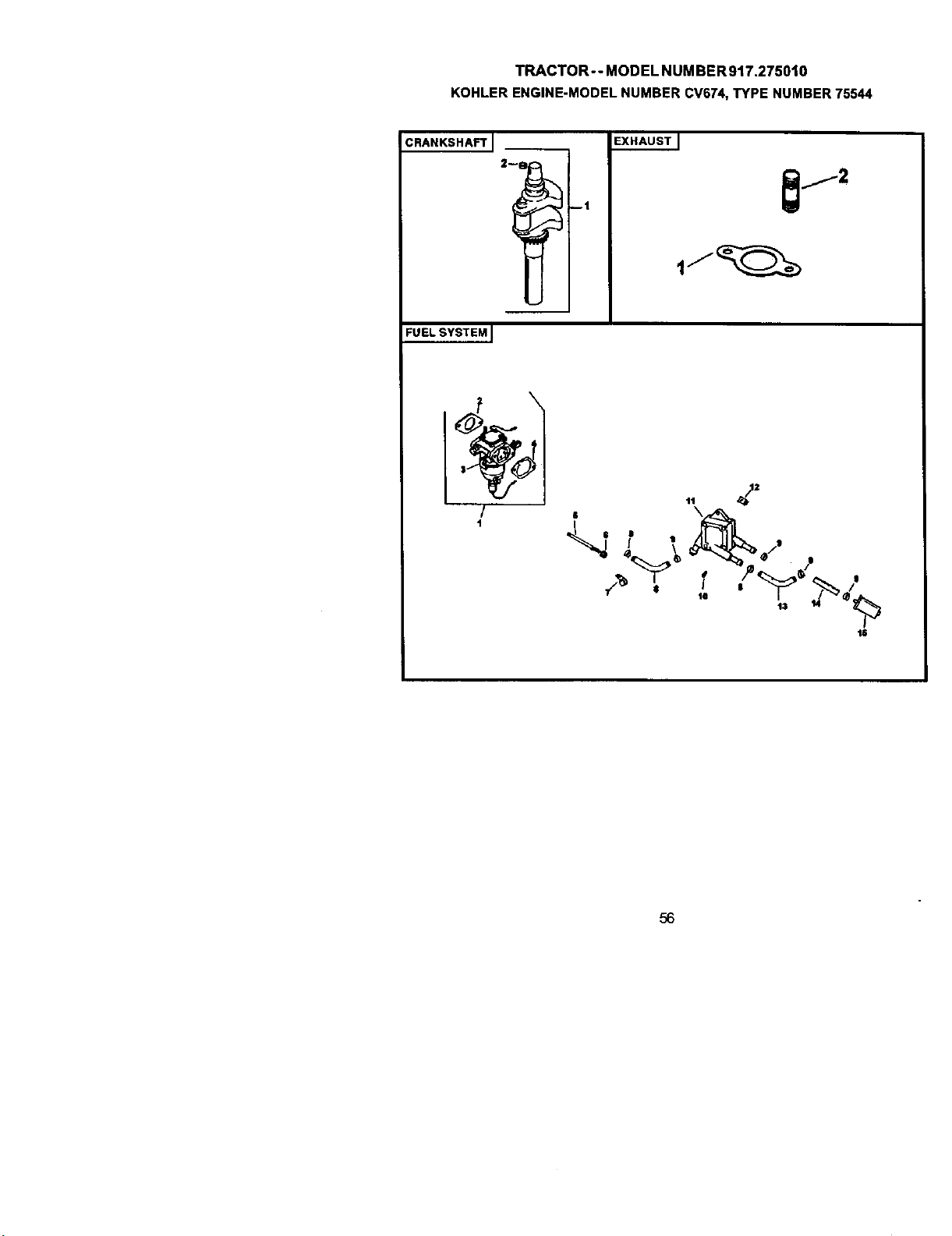
TRACTOR--MODELNUMBER917.275010
KOHLERENGINE-MODELNUMBERCV674,TYPENUMBER75544
CRANKSHAFTJ
EXHAUSTJ
--1
FUELSYSTEM I
/
1
11
6
_2
18
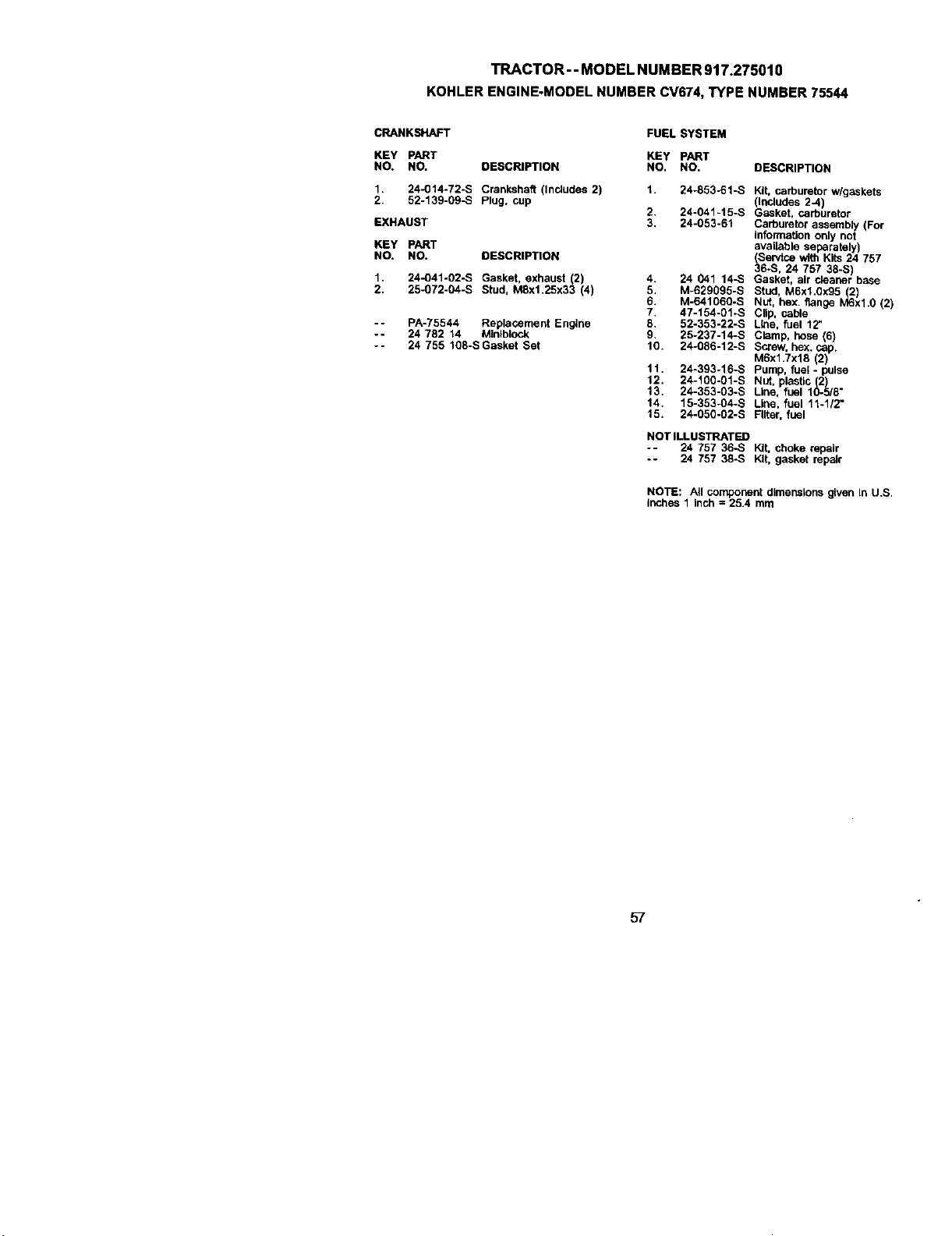
TRACTOR -- MODEL NUMBER 917.275010
KOHLERENGINE-MODELNUMBERCV674,TYPENUMBER75544
CRANKSHAFT FUEL SYSTEM
KEY PART KEY PART
NO. NO. DESCRIPTION NO. NO,
1. 24-014-72-S Crankshaft (Includes 2) 1. 24-853-61-S
2. 52-139-09-S Plug, cup
2. 24-041-15-S
EXHAUST 3. 24-053-61
KEY PART
NO. NO. DESCRIPTION
1. 24-041-02-S Gasket, exhaust (2)
2. 25-072-04-S Stud, M8x1.25x33 (4)
-- PA-75544 Replacement Engine
-- 24 782 14 Minlbiock
-- 24 755 108-SGasket Set
4. 24 041 14-S
5. M-629095-S
6. M-641060.S
7. 47-154-0%S
8. 52-353-22-S
9. 25-237-14-S
10. 24-086-12-S
11. 24-393-16-S
12. 24-100-01-S
13. 24-353-03-S
14, 15-353-04-S
15. 24-050-02-S
DESCRIPTION
Kit, carburetor w/gaskets
(Includes 2-4)
Gasket, carburetor
Carburetor assembly (For
infoffnation only not
available separately)
(Servtse with Kits 24 757
36-S, 24 757 38-S)
Gasket, air cleaner base
Stud, M6x1.0)(95(2)
Nut, hex. flange M6xl.0 (2)
Clip, cable
Line, fuel 12"
Clamp, hose (6)
Screw, hex. cap.
M6x1.7x18 (2)
Pump, fuel - pulse
NUt, plastic (2)
Line, fuel 10-5/8"
Line, fuel 11-1/2"
Filter, fuel
NOT ILLUSTRATED
-- 24 757 36-S Kit, choke repair
-- 24 757 38-S Kit, gasket repair
NOTE: All component dimensions given In U.S.
inches 1 inch = 25.4 mm
57

58
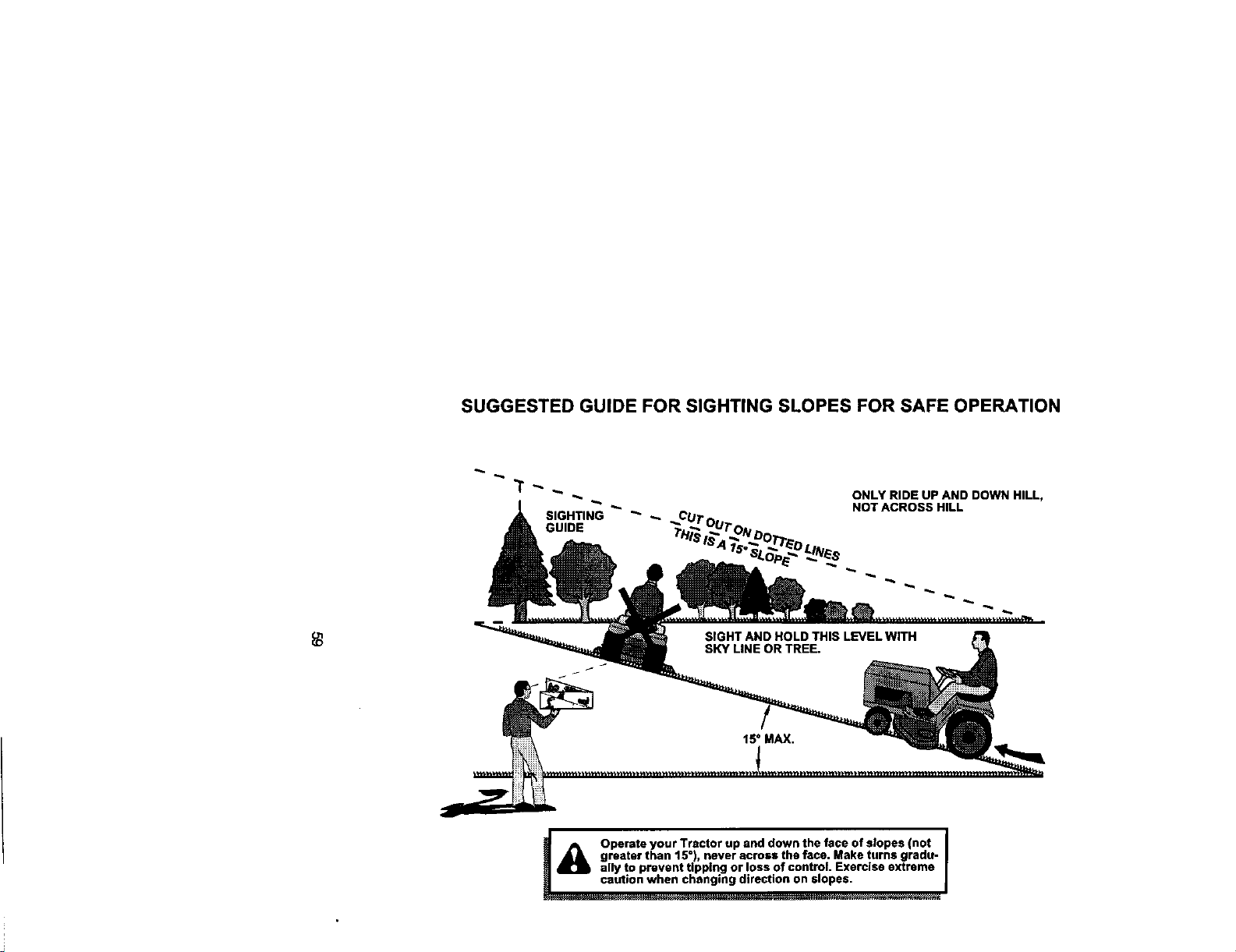
SUGGESTED GUIDE FOR SIGHTING SLOPES FOR SAFE OPERATION
ONLY RIDE UP AND DOWN HILL,
NOT ACROSS HILL
A Operate your Tractor up and down the face of slopes (not
greater than 15°), never across the face. Make turns gradu -
ally to prevent tipping or loss of control. Exercise extreme
__ ml_es.
Forrepairofmajorbrandappliar_:e6inyourown home...
nomatterwhomadeit,nomatterwhosold
1-800-4-MY-HOME _ /w/_ne,dayorn_J_t
(1-8oo.469-4863) (u.s.A.andCanada)
Forrepairofcarry4nproductslikevacuums,lav_ equipment,and
elecb'onics,callforthenearestSearsPartsand RepairCenter.
1-800-488-1222 An,/drne,dayorrigtt(U.S.Aorgy)
wt_N.r, esIs.conl
Forthereplacementparts,accessoriesandowner'smanuals
thatyouneedtodo-it-yourself,callSearsPartsDirectS"!
1-800-366-PART 6a.m.-11 p.m., 7daysaweek
(1-aem3ee-7278) (u.sJ_ore)
wva_.sears.com/mrtsdi_t
To purchaseor inquireaboutaSearsServiceAgreement
or SearsMaintenanceAgreement:
1-600-627-6655 (u.s._) 1-800-361-6665 (Canada)
7a_m.- 5 p.m.,CST,M_ - Sat. 9 a.m.- 8p.m.EST,M- F, 4p.m.Sat.
® Registered Trademark / '_ Trademark I s_ Service Mark of Seam, Roebuck and Co.
® Marca RegJstrada I "n_Mama de Fdbdca / sv Marca de Servtclo de Sears, Roebuck and Co.
MCMarque de commerce / MDMarque d_pos_e de Sears, Roebuck and Co.
177667 01.10.01 RH Printed in U.S.A.


