
Smart ANPR Camera
Web Operation Manual
V1.0.0

I
Foreword
General
This manual introduces the functions and operations of the smart camera with access automatic
number plate recognition (hereinafter referred to as "the camera"). Read carefully before using the
device, and keep the manual safe for future reference.
Safety Instructions
The following signal words might appear in the manual.
Signal Words Meaning
Indicates a high potential hazard which, if not avoided, will result in
death or serious injury.
Indicates a medium or low potential hazard which, if not avoided,
could result in slight or moderate injury.
Indicates a potential risk which, if not avoided, could result in property
damage, data loss, reductions in performance, or unpredictable
results.
Electrostatic Sensitive Devices.
Indicates a device that is sensitive to electrostatic discharge.
Indicates dangerous high voltage.
Take care to avoid coming into contact with electricity.
Indicates a laser radiation hazard.
Take care to avoid exposure to a laser beam.
Provides methods to help you solve a problem or save time.
Provides additional information as a supplement to the text.
Revision History
Version Revision Content Release Time
V1.0.0 First release. December 2022
Privacy Protection Notice
As the device user or data controller, you might collect the personal data of others such as their face,
fingerprints, and license plate number. You need to be in compliance with your local privacy
protection laws and regulations to protect the legitimate rights and interests of other people by
implementing measures which include but are not limited: Providing clear and visible identification
to inform people of the existence of the surveillance area and provide required contact information.
About the Manual
●
The manual is for reference only. Slight differences might be found between the manual and the
product.
●
We are not liable for losses incurred due to operating the product in ways that are not in
compliance with the manual.
●
The manual will be updated according to the latest laws and regulations of related jurisdictions.

II
For detailed information, see the paper user’s manual, use our CD-ROM, scan the QR code or visit
our official website. The manual is for reference only. Slight differences might be found between
the electronic version and the paper version.
●
All designs and software are subject to change without prior written notice. Product updates
might result in some differences appearing between the actual product and the manual. Please
contact customer service for the latest program and supplementary documentation.
●
There might be errors in the print or deviations in the description of the functions, operations
and technical data. If there is any doubt or dispute, we reserve the right of final explanation.
●
Upgrade the reader software or try other mainstream reader software if the manual (in PDF
format) cannot be opened.
●
All trademarks, registered trademarks and company names in the manual are properties of their
respective owners.
●
Please visit our website, contact the supplier or customer service if any problems occur while
using the device.
●
If there is any uncertainty or controversy, we reserve the right of final explanation.

III
Important Safeguards and Warnings
This section introduces content covering the proper handling of the device, hazard prevention, and
prevention of property damage. Read carefully before using the device, and comply with the
guidelines when using it.
Transportation Requirements
Transport the device under allowed humidity and temperature conditions.
Storage Requirements
Store the device under allowed humidity and temperature conditions.
Installation Requirements
●
Do not connect the power adapter to the device while the adapter is powered on.
●
Strictly comply with the local electric safety code and standards. Make sure the ambient voltage
is stable and meets the power supply requirements of the device.
●
Do not connect the device to two or more kinds of power supplies, to avoid damage to the
device.
●
Personnel working at heights must take all necessary measures to ensure personal safety
including wearing a helmet and safety belts.
●
Do not place the device in a place exposed to sunlight or near heat sources.
●
Keep the device away from dampness, dust, and soot.
●
Put the device in a well-ventilated place, and do not block its ventilation.
●
Use an adapter or cabinet power supply provided by the manufacturer.
●
Make sure the power supply meets the SELV (Safety Extra Low Voltage) requirements, and rated
voltage conforms to the IEC60065, IEC60950-1 or IEC62368-1 standard. The requirements of the
power supply are subject to the device label.
●
The device is a class I electrical appliance. Make sure that the power supply of the device is
connected to a power socket with protective earthing.
Operation Requirements
●
Check whether the power supply is correct before use.
●
Do not unplug the power cord on the side of the device while the adapter is powered on.
●
Operate the device within the rated range of power input and output.
●
Use the device under allowed humidity and temperature conditions.
●
Do not drop or splash liquid onto the device, and make sure that there is no object filled with
liquid on the device to prevent liquid from flowing into it.
●
Do not disassemble the device without professional instruction.

IV
Table of Contents
Foreword
........................................................................................................................................................................................................I
Important Safeguards and Warnings
............................................................................................................................................ III
1 Introduction
............................................................................................................................................................................................ 1
1.1 Overview
........................................................................................................................................................................................ 1
1.2 Features
.......................................................................................................................................................................................... 1
2 Web Configuration
.............................................................................................................................................................................. 3
2.1 Web Login
...................................................................................................................................................................................... 3
2.1.1 Recommended System Requirements
................................................................................................................. 3
2.1.2 Device Initialization
....................................................................................................................................................... 4
2.1.3 Login
..................................................................................................................................................................................... 5
2.1.4 Resetting Password
....................................................................................................................................................... 6
2.1.5 Web Functions
.................................................................................................................................................................. 7
2.2 Wizard
............................................................................................................................................................................................. 8
2.3 Live
.................................................................................................................................................................................................... 9
2.3.1 Video Stream
................................................................................................................................................................... 10
2.3.2 Live View
........................................................................................................................................................................... 10
2.3.3 Recognized Plate Number
........................................................................................................................................ 11
2.3.4 Plate Snapshot
............................................................................................................................................................... 11
2.3.5 System Functions
.......................................................................................................................................................... 11
2.3.6 Live Page Functions
..................................................................................................................................................... 11
2.3.7 Vehicle Snapshot
.......................................................................................................................................................... 13
2.3.8 Event List
........................................................................................................................................................................... 13
2.4 Search
............................................................................................................................................................................................ 13
2.4.1 Picture Query
.................................................................................................................................................................. 13
2.4.1.1 Memory Card Image
......................................................................................................................................... 13
2.4.1.2 Local Image
........................................................................................................................................................... 14
2.4.2 Recording Search
.......................................................................................................................................................... 14
2.4.2.1 Recording
............................................................................................................................................................... 14
2.4.2.2 Watermark
............................................................................................................................................................. 15
2.4.3 Snapshot Record Search
............................................................................................................................................ 16
2.4.4 Alarm Query
.................................................................................................................................................................... 17
2.5 Setting
........................................................................................................................................................................................... 17
2.5.1 ANPR
.................................................................................................................................................................................... 17
2.5.1.1 Setting Snapshot
................................................................................................................................................ 17
2.5.1.2 AI Setting
................................................................................................................................................................ 20
2.5.1.2.1 Configuring Intelligent Analysis
..................................................................................................... 20
2.5.1.2.2 Selecting Recognition Scene
............................................................................................................. 20
2.5.1.3 Configuring OSD
................................................................................................................................................ 21

V
2.5.1.3.1 Video OSD
................................................................................................................................................... 21
2.5.1.3.2 Original Picture OSD
.............................................................................................................................. 23
2.5.1.4 Configuring Cutout
........................................................................................................................................... 24
2.5.1.4.1 Snapshot Cutout
...................................................................................................................................... 24
2.5.1.4.2 Plate Overlay
............................................................................................................................................. 24
2.5.1.5 Setting Blocklist and Allowlist for Vehicles
.......................................................................................... 25
2.5.1.5.1 Allowlist
....................................................................................................................................................... 25
2.5.1.5.2 Blocklist
........................................................................................................................................................ 26
2.5.1.6 Configuring Barrier Control
.......................................................................................................................... 26
2.5.1.6.1 Barrier Control
.......................................................................................................................................... 26
2.5.1.6.2 Remote Controller
.................................................................................................................................. 27
2.5.1.7 Configuring RS-485 Settings
........................................................................................................................ 27
2.5.1.8 Configuring RS-485 Peripheral
................................................................................................................... 29
2.5.1.9 Setting Time Schedule
..................................................................................................................................... 30
2.5.1.10 Configuring LED Screen
............................................................................................................................... 30
2.5.1.11 Configuring Broadcast
................................................................................................................................. 32
2.5.1.11.1 Event Broadcast Settings
................................................................................................................. 32
2.5.1.11.2 Voice Broadcast Settings
.................................................................................................................. 33
2.5.1.11.3 Volume/Encoding Settings
.............................................................................................................. 34
2.5.1.12 Setting Device Test
......................................................................................................................................... 34
2.5.1.12.1 Device Test
............................................................................................................................................... 34
2.5.1.12.2 Capture Adjustment Information
................................................................................................ 35
2.5.1.12.3 Collection Log
........................................................................................................................................ 36
2.5.2 Camera
............................................................................................................................................................................... 36
2.5.2.1 Configuring Image Attributes
..................................................................................................................... 36
2.5.2.1.1 General
......................................................................................................................................................... 36
2.5.2.1.2 Shutter
.......................................................................................................................................................... 38
2.5.2.1.3 Metering
...................................................................................................................................................... 39
2.5.2.2 Configuring Video Parameters
................................................................................................................... 40
2.5.2.2.1 Video
............................................................................................................................................................. 40
2.5.2.2.2 Snapshot
...................................................................................................................................................... 40
2.5.2.2.3 ROI
.................................................................................................................................................................. 41
2.5.3 Network Settings
.......................................................................................................................................................... 41
2.5.3.1 Configuring TCP/IP
............................................................................................................................................ 41
2.5.3.2 Configuring Port
................................................................................................................................................. 42
2.5.3.3 Configuring DDNS
............................................................................................................................................. 42
2.5.3.4 Configuring Register
........................................................................................................................................ 42
2.5.3.5 Configuring Multicast
...................................................................................................................................... 42
2.5.3.6 Configuring Email
.............................................................................................................................................. 43
2.5.3.7 Configuring SNMP
............................................................................................................................................. 43

VI
2.5.3.8 Configuring 802.1x
........................................................................................................................................... 44
2.5.3.9 Configuring PPPoE
............................................................................................................................................ 44
2.5.3.10 Configuring Platform Access
..................................................................................................................... 45
2.5.3.10.1 P2P
............................................................................................................................................................... 45
2.5.3.10.2 ONVIF
......................................................................................................................................................... 45
2.5.3.10.3 Info Push Platform
............................................................................................................................... 45
2.5.4 Event
................................................................................................................................................................................... 46
2.5.4.1 Alarm
........................................................................................................................................................................ 47
2.5.4.1.1 Enabling Alarm-in and Alarm-out Ports
...................................................................................... 47
2.5.4.1.2 Alarm-out Port
.......................................................................................................................................... 47
2.5.4.2 Abnormality
.......................................................................................................................................................... 47
2.5.4.3 Defocus Detection
............................................................................................................................................. 48
2.5.4.4 IVS
.............................................................................................................................................................................. 49
2.5.5 Storage
............................................................................................................................................................................... 49
2.5.5.1 Storage Spot Config
......................................................................................................................................... 50
2.5.5.2 Local Storage
....................................................................................................................................................... 50
2.5.5.3 FTP
............................................................................................................................................................................. 50
2.5.5.4 Platform Server
................................................................................................................................................... 52
2.5.5.5 Storage Path
......................................................................................................................................................... 52
2.5.6 System
................................................................................................................................................................................ 52
2.5.6.1 General
.................................................................................................................................................................... 52
2.5.6.1.1 General Setup
........................................................................................................................................... 52
2.5.6.1.2 Date & Time
................................................................................................................................................ 53
2.5.6.2 Account
................................................................................................................................................................... 53
2.5.6.2.1 Account Management
.......................................................................................................................... 53
2.5.6.2.2 ONVIF User
................................................................................................................................................. 55
2.5.6.3 Security
................................................................................................................................................................... 55
2.5.6.3.1 System Service
.......................................................................................................................................... 55
2.5.6.3.2 HTTPS
............................................................................................................................................................ 56
2.5.6.3.3 Firewall
......................................................................................................................................................... 62
2.5.6.4 Default Settings
.................................................................................................................................................. 62
2.5.6.5 Import/Export
...................................................................................................................................................... 62
2.5.6.6 System Maintenance
........................................................................................................................................ 62
2.5.6.7 Update
..................................................................................................................................................................... 63
2.5.7 System Info
...................................................................................................................................................................... 63
2.5.7.1 Version
.................................................................................................................................................................... 63
2.5.7.2 Log
............................................................................................................................................................................. 64
2.5.7.2.1 System Log
................................................................................................................................................. 64
2.5.7.2.2 Remote log
................................
................................................................................................................. 64
2.5.7.3 Online User
............................................................................................................................................................ 65

VII
2.5.7.4 Running Status
.................................................................................................................................................... 65
2.6 Alarm
.............................................................................................................................................................................................. 65
2.7 Logout
........................................................................................................................................................................................... 65
3 FAQ
............................................................................................................................................................................................................ 66
Appendix 1 Cybersecurity Recommendations
........................................................................................................................ 67

1
1 Introduction
1.1 Overview
The camera adopts intelligent deep learning algorithm. It supports vehicle detection, recognition of
license plate, logo, model, and color, and encoding mode such as H.265.
The camera consists of a protective housing, illuminator, and intelligent HD camera. The intelligent
HD camera adopts progressive scanning CMOS, which features high definition, low illuminance, high
frame rate, and excellent color rendition.
1.2 Features
The features are available on select models, and might differ from the actual camera.
Permission Management
●
Each user group has its own permissions. Permissions of a user cannot exceed the permissions of
its group.
●
2 user levels.
●
Permission of opening barrier, and blocklist alarm function.
●
Device configuration, and permission management through Ethernet.
Storage
●
Stores corresponding video data onto the central server according to the configuration (such as
alarm, and timing settings).
●
Users can record videos on the webpage according to their requirements. The recorded video file
will be stored on the computer where the client is located.
●
Supports hot swapping of storage card, and storage when network is disconnected. It overwrites
stored pictures, and videos automatically when memory becomes insufficient.
●
Stores 1024 log records, and user permission control.
●
Supports FTP storage, and ANR (automatic network replenishment).
Alarm
●
It can trigger alarm upon camera operation exceptions through network, such as memory card
damage.
●
Some devices can connect to various alarm peripherals to respond to external alarm input in real
time (within 200 ms). It can correctly deal with various alarms according to the linkage
predefined by users, and generate corresponding voice prompt (users are allowed to record
voice in advance).
Network Monitoring
●
Transmits video data of single channel compressed by device to network terminal, and makes it
reappear after decompression through network. Keep delay within 500ms when bandwidth is
allowed.
●
Supports up to 10 users online at the same time.
●
Supports system access, and device management through the webpage of the device.

2
●
Video data transmission adopts HTTP, TCP, UDP, MULTICAST, and RTP/RTCP.
Capture and Recognition
●
Recognizes plate number, color, logo, model, and other features of vehicles.
●
Supports setting OSD information, and configuring location of channel, and picture.
●
Supports capturing and encoding images. Supports watermark encryption on images to prevent
them from being tampered.
●
The captured pictures contain the time, location, license plate, color, and more on the vehicle.
Peripheral Control
●
Peripheral control: Supports setting various peripheral control protocols, and connection pages.
●
Connects to external devices such as vehicle detector, signal detector, and more.
Auto Adjustment
●
Auto iris: Automatically adjusts the iris opening to the changing light throughout the day.
●
Auto white balance: Accurately displays the object color when light condition changes.
●
Auto exposure: Automatically adjusts shutter speed according to the exposure value of the
image measured by the metering system, and according to shutter, and iris exposure set by
factory defaults.
●
Auto gain: Automatically increases camera sensitivity when illuminance is very low, enhancing
image signal output so that the camera can acquire clear, and bright image.

3
2 Web Configuration
You can log in to webpage of the device through a browser on your PC, and configure and operate
it.
The functions might vary depending on the model you purchased. The pages, and settings are for
reference only, and might differ from the actual page.
2.1 Web Login
2.1.1 Recommended System Requirements
You can access the camera through browsers with or without the plugin. If you do not use the
plugin, you will not be able to user certain functions.
●
When using a browser with the plugin, you can get a complete experience. We recommend
using Internet Explorer.
Table 2-1 Recommended system requirements-with plugin
PC Component Recommended System Requirements
Operating
System
Windows 7, and later
CPU Intel core i3, and faster processor
Graphics Intel HD Graphics, and later
RAM 2 GB, and larger
Monitor 1024 × 768, and higher
Browser Internet Explorer 9/11, Chrome 33/41, Firefox 49
●
If Internet Explorer is not available, you can use Chrome. For Chrome, make sure that your
computer meet the requirements included in the table below.
◇
If you are using a computer with lower performance, we recommend you use sub stream to
eliminate video lags.
◇
When using a 4 MP camera, adjust the video frame rate to 15 fps.
Table 2-2 Recommended system requirements-without plugin
PC Component Recommended System Requirements
Operating
System
Windows 7, and later
CPU Intel core i5 6500, and faster
Graphics Intel HD Graphics, and later
RAM 16 GB, and larger
Monitor 1024 × 768, and higher
Browser Chrome 92 and newer

4
Browsers that do not support plug-in might have trouble displaying certain videos and images, or
downloading data in batches. The camera reminds you when that happens.
Figure 2-1 Reminder
2.1.2 Device Initialization
The camera is delivered uninitialized by default. You need to initialize it, and change its password
before further operations. Before initialization, make sure that both PC IP, and device IP are on the
same network segment, otherwise you might fail to go to the initialization page.
Procedure
Step 1 Set the IP address, subnet mask, and gateway of PC and device respectively.
●
If there is no router in the network, distribute IP address of the same segment.
●
If there is router in the network, configure the corresponding gateway, and subnet
mask.
●
The IP address is 192.168.1.108 by default.
Step 2 Ping the IP address of the camera to check whether network is connected.
Step 3 Go to the IP address of the camera in a browser.
Step 4 Enter and confirm the password.
●
The new password must consist of 8 to 32 characters, and contain at least two types
from upper case, lower case, number, and special characters (excluding ' " ; :, and &).
●
If you want to change your password again, go to
Setting
>
System
>
Account
>
Account
.
Step 5 Select the
Email Address
checkbox, and then enter your email address (recommended to
set for resetting your password).
Step 6 Click
Confirm
.

5
Figure 2-2 Device Initialization
Step 7 Enter the username and password, and then click
Login
.
Figure 2-3 Login
●
A pop-up prompts when the username or password is incorrect to reminds you of
remaining attempts.
●
The account will be locked for 300 s if you enter incorrect username or password for 5
times consecutively.
Step 8 Click
Please click here to download
, and install the plug-in in the video window.
After download is complete, install it according to the on-screen instructions.
Before installing plug-in, make sure that in
Internet Option
>
Security
>
Settings
, the
associated plug-in option of active has been modified as
Enable
or
Prompt
.
2.1.3 Login
You can log in to the webpage by following the steps below. For first-time login or login after
restoring factory default settings, see "2.1.2 Device Initialization".
Procedure
Step 1 Enter the IP address of the camera in the browser address bar, and then press Enter.

6
Step 2 Enter your login username, and password, and then click
Login
.
2.1.4 Resetting Password
Reset the password when you forget or want to change it.
●
When scanning the QR code to acquire the security code, one QR code supports up to 2
acquisition.
●
The security code received through email is only valid for 24 hours.
●
One device can generate up to 10 security codes in one day, so you can change the password 10
times at most in one day.
●
Email address must be filled in during device initialization; otherwise you will not receive the
security code. The email address of admin can be modified under
Setting
>
System
>
Account
>
Account
.
Procedure
Step 1 Open the browser, enter the IP address of the camera in the browser address bar, and then
press Enter.
Step 2 Click
Forgot password?.
Figure 2-4 Information
Step 3 Click
OK
.
If you use IE browser, the system might prompt
Stop running the script
, click
No
, and
continue to run the script.
Step 4 Scan the QR code according to the page prompt, and send the scanning result to
designated email to get the security code.

7
Figure 2-5 Reset password (1)
Scan the actual QR code.
Step 5 Enter the received security code.
Step 6 Click
Next
.
Figure 2-6 Reset password (2)
Step 7 Set
Password
, and enter your new password again in
Confirm Password
.
Step 8 Click
Yes
.
2.1.5 Web Functions
This section mainly introduces the following 6 functions on the webpage.
Figure 2-7 Tab

8
Table 2-3 Tab function description
Tab Function
Wizard Quick configuration of plate pixel, recognition region, and more.
Live
View, and record live video, and image, adjust the video and image window, set
client image parameter, and more.
Search
Search for different types of pictures and videos, and configure watermark
verification of videos.
Setting
Set traffic event rules, basic attributes of the camera , network, storage, and
system, and view system information.
Alarm Set alarm prompt.
Logout Log out of the web client.
The following buttons are very common on the webpage.
Table 2-4 Common buttons description
Button Description
Restore all parameters to system defaults.
Refresh the parameters to the latest value.
Save the settings.
2.2 Wizard
On the
Wizard
page, you can configure capture scenarios, and get assistance with setting
installation scenarios.
You can click at the upper-right corner of the
Wizard
page to exit.
Procedure
Step 1 Click the
Wizard
tab.
Step 2 Select the basic date and time format and system time of the camera, and then click
Save
.
●
You can manually enter the time, or click
Sync PC
to synchronize time from the server.
●
Set
Plate Algorithm
to your region to get better results.

9
Figure 2-8 Basic parameters
Step 3 Click
Drawing
to see whether the video image is properly zoomed, and focused by
checking the plate pixel.
Figure 2-9 Drawing
1) Drag the zoom, and focus bars to adjust the video image until the image is clear.
2) Follow the tips on the figure on the right side, and then draw an area for capturing
vehicles that enter.
3) Click
Add
next to
Shield Area
to draw areas that the camera does not recognize.
Click
Delete
to delete the area.
4)
Realtime Display
window in the middle displays the plate recognition result cutout at
the upper-left corner and vehicle image in real-time.
5) Click
Save
.
Step 4 Click
Finish
, and then click
Finish
in the middle to exit the
Wizard
page.
Click
Back
to go back to the last step during the guide.
2.3 Live
Click the
Live
tab.
On this page, you can view live videos and real-time capture images, record videos, config LPR, and

10
more.
Figure 2-10 Live
Table 2-5 Live page description
No. Description No. Description
1 Video stream 5 System functions
2 Live view 6 Functions of the Live page
3 Recognized plate number 7 Vehicle snapshot
4 Plate snapshot 8 Event list
2.3.1 Video Stream
●
Main Stream
: Make sure that the camera can record video, and perform network surveillance
when the network is normal. You can configure main stream resolution within the supported
range of the camera.
●
Sub Stream
: Replaces main stream to make network surveillance, and reduce the network
bandwidth possession when network bandwidth is insufficient.
●
Protocol
: Video surveillance protocol, currently it only supports
TCP
.
●
Fluency
: Smoothness when viewing the live video. The fluency can be set to
High
,
Middle
,
Low
,
and
Default
(recommended).
2.3.2 Live View
Displays the live video captured by the camera. You can also click the icons to change the display
mode of live view.
●
: Adjust the image to its original size or fill the window.
●
: Switch to a big window.

11
Figure 2-11 Big window
●
: Click to enable smart track detection. Plate number, vehicle bounding box, and other smart
tracking information will be displayed on the video image.
●
: Click to display the window in full screen; double-click or right-click to exit full screen.
2.3.3 Recognized Plate Number
Displays the plate number recognized by the camera in real time when a vehicle passes.
2.3.4 Plate Snapshot
Displays the snapshot of the license plate when a vehicle passes.
2.3.5 System Functions
Click the tabs to set system functions, including playback, video recording, and snapshot query,
intelligent rules setting, alarm event setting, and system logout.
2.3.6 Live Page Functions
This section introduces operations such as image and video capture, zoom, record, and talk.
Figure 2-12 General function
Table 2-6 General function option
Icons Name Description
ANPR Receive
Select the checkbox, and the camera automatically
receives vehicle snapshots, and detects event
information triggered by sources such as radar or
video detection, and displays such snapshots, and
information at the lower part of the page.
The snapshots are saved in the storage path defined
in
Setting
>
Storage
>
Destination
>
Save Path
.

12
Icons Name Description
Record Type
Select the format of video recordings (
dav
by
default).
Talk
Click it, and then you can communicate with people
on site through the camera.
Manual Snapshot
Click to take a snapshot when a vehicle passes.
Snapshots are saved on the storage path.
●
Enable
ANPR Receive
first.
●
To change the storage path of snapshots, go to
Setting
>
Storage
>
Destination
>
Save Path
.
Digital Zoom
Drag to select an area in the video, and then the
area will be zoomed in. Right-click anywhere on the
video, or click to exit.
Video Recording
Click it to start recording. Click again to stop
recording. You can set the storage path of video
recordings in
Setting
>
Storage
>
Destination
>
Save Path
.
Config (LPR)
You can draw the area of plate detection, adjust
camera’s focal length, and set applicable regions.
Procedure
Step 1 Click to configure LPR.
Figure 2-13 Config (LPR)
Step 2 Set the focus and zoom mode, which is used to recognize vehicle.
Table 2-7 Focus parameter description
Parameter Description
Auto Focus Auto adjust camera lens, and make the scenario clearly focused.
Regional
Click
Regional
, and then draw a box in the video image to focus the
defined region in the box.

13
Parameter Description
Manual Focus
●
Zoom
: Click to zoom in, click to zoom out. You can also
directly drag the adjustment bar.
●
Focus
: Click to focus on far places, click to focus on near
places. You can also directly drag the adjustment bar to set focal
length.
●
Speed
: There are 3 levels to be selected. The higher the speed, the
more obvious the adjustment.
Restore All Restore all configurations to default settings.
Shield Area
Click
Add
to draw a shield area on the video image where the camera
does not detect.
Illumination
Click
Illumination
, and the page is directed to the camera attribute. You
can set the illumination there.
Plate Algorithm
Select the algorithm to recognize the plate. The recognized result is
displayed below.
Step 3 Click
Save
.
2.3.7 Vehicle Snapshot
Select
ANPR Receive
, and then snapshots will be displayed when vehicles pass.
2.3.8 Event List
Select
ANPR Receive
, and the event information will be displayed, including number, event types,
capture time, lanes, plates, vehicle color, speed, vehicle signs, and vehicle types.
2.4 Search
Click the
Query
tab, and the system displays query page where you can search for pictures, and
video recordings.
2.4.1 Picture Query
2.4.1.1 Memory Card Image
Search conditions can be set in this section. You can search for event, and plate information of the
SD card within the set period.
Procedure
Step 1 Select
Search
>
Picture Query
>
Memory Card Image
.

14
Figure 2-14 Memory card picture
Step 2 Set the search conditions.
●
Set the begin and end time of search period.
●
Select
Event Type
.
●
Select
Plate
to enter plate number.
Step 3 Click
Search
, and it displays the results which conform to search conditions.
●
Select a file on the list, and the captured image of the plate will be displayed in
Real
Plate
.
●
Select pictures, and then click
Open
to see the corresponding vehicle snapshot.
Step 4 Select one or more pictures to be downloaded to local PC.
●
Click
Download by File
, the selected pictures will be downloaded to the defined path.
●
Click
Download by Time
, all the results which are captured within the set period will
be downloaded to the defined path.
2.4.1.2 Local Image
The section introduces the way of checking whether the watermark of PC picture is tampered.
Procedure
Step 1 Select
Search
>
Picture Search
>
Local Picture
.
Step 2 Click
Browse
, and select the folder where the verified picture is located.
Step 3 Select the picture which needs to be verified, and then click
Open
.
Step 4 Click
Watermark
. The camera starts verifying whether the picture has watermark and
displays the results on the picture list under
Watermark Verification
.
Select pictures and click
Open
or double-click the picture if you need to preview the
picture.
2.4.2 Recording Search
2.4.2.1 Recording
You can play videos that are stored on your computer.
Procedure
Step 1 Select
Search
>
Search Video
>
Record
.

15
Figure 2-15 Search for recording
Step 2 Click
Select File
, select record path, click
Open
, and view the video.
Table 2-8 Play function description
Icon Description
●
: Play video.
●
: Pause.
Stop playing video.
Slow down video playing.
Speed up video playing.
Next frame.
2.4.2.2 Watermark
You can verify whether the watermark of local recordings is tampered.
Go to
Setting
>
Camera
>
Video
>
Video Stream
, and select
Watermark
to enable the function,
and set the corresponding
Watermark String
. The default character is DigitalCCTV.
Procedure
Step 1 Select
Search
>
Search Video
>
Watermark
.

16
Figure 2-16 Watermark
Step 2 Click
Select File
, and select a file that you want to verify.
Step 3 Click
Watermark
, and the system displays verifying progress and normal watermark.
The results will be shown in the
Tampered Watermark
section.
2.4.3 Snapshot Record Search
Search for the vehicle records within the defined period according to the defined direction.
●
The camera can store up to 10,000 records when no memory card is installed.
●
If the vehicle passing records are unreadable in Excel after it is imported, change them into UTF-8
encoding document in txt, and then the Excel file can be opened normally.
Procedure
Step 1 Select
Search
>
Snapshot Record Search
.
Step 2 Set
Start Time
, and
End Time
, and then set the
ANPR Direction
(vehicle movement
direction).
Step 3 Click
Search
to search for the plates that meet the search conditions.
Figure 2-17 Capture records
Step 4 Click
Export All
or
Export by Time
to export all results or the searched results based on
the conditions to PC.

17
2.4.4 Alarm Query
Set the search conditions to search alarm output.
Make sure that all the external devices are connected with the camera through RS-485 port.
Procedure
Step 1 Select
Search
>
Alarm Query
.
Step 2 Set the start time and end Time.
Step 3 Click
Search
.
Figure 2-18 Alarm output search
Click
Export All
or
Export by Time
to export all results or the searched results.
2.5 Setting
You can configure several parameters such as ANPR, camera, network, event, storage, system, and
system information.
2.5.1 ANPR
You can set intelligent parameters of the camera.
2.5.1.1 Setting Snapshot
You can set snapshot rule of the camera.
Procedure
Step 1 Select
Setting
>
ANPR
>
Snapshot Setting
.

18
Figure 2-19 Snapshot settings-video mode
Figure 2-20 Snapshot settings-loop mode
Step 2 Configure the parameters.
Table 2-9 Description of capture parameters
Type Parameter Description
General Parameters
Capture Mode
●
Loop
: Use loop to take snapshots.
●
Video
: Use video to take snapshots.
●
Mix Mode
: Use both loop and video to take
snapshots.
Snapshot Quantity It can take 1–2 snapshot(s).
Driving Direction to
Trigger Snapshot
●
Positive
: Only captures vehicles that
approach.
●
Departing
: Only captures vehicles that
depart.
●
Both Ways
: Captures vehicles that
approach or depart.
Delay for Prevention
of Same Plate
Capture
Set the time interval during which one plate
can only be captured once.
Video Mode
Parameters
Scene
Select
Small Vehicle
or
Large Vehicle
as
needed.
Unlicensed Vehicle
Snapshot
Click to enable the capture towards unlicensed
motor vehicles.

19
Type Parameter Description
Only available when
the
Snap Mode
is set
to
Video
.
Frames to Output
Licensed Vehicle
Snapshot
Configure the frame number of capturing
licensed vehicle.
1
(default) means to capture
when detecting one frame of licensed vehicle
passing detection area.
Frames to Output
Unlicensed Vehicle
Snapshot
Configure the frame number of capturing
unlicensed vehicle.
10
(default) means to
capture when detecting 10 frames of
unlicensed vehicle passing detection area.
Loop Mode
Parameters
Only available when
the
Snap Mode
is set
to
Loop
.
Plan
Set the scheme of snapshots triggered by the
loop.
●
single_in-snap_nospeed
: Lay single loop,
and it will take a snapshot when the vehicle
enters a loop.
●
double_in1-snap_nospeed
: Lay double
loops, and it will take a snapshot when the
vehicle enters the first loop.
●
double_in2-snap_speed
: Lay double
loops, and it will take a snapshot when the
vehicle enters the second loop.
Loop No. Mapping
Select the corresponding relationship between
logical loop and physical loop.
●
When the scheme is
single_in-
snap_nospeed
, only need to select the
physical loop corresponds to logical loop 1.
●
You need to configure this in mix mode.
Loop1 Set the loop trigger mode.
●
Do Not Trigger
: No capture is triggered.
●
Rising Edge
: Capture is triggered when the
vehicle enters loop.
●
Falling Edge
: Capture is triggered when
the vehicle exits the loop.
When the scheme is
single_in-snap_nospeed
,
then loop 2 cannot be set.
Loop2
Max Vehicle Pass
Time
Set a time period, during which a vehicle enters
the first loop and triggers the second, the
camera only takes snapshots for the first
trigger.
Applicable for double loops.
Step 3 Click
Save
.

20
2.5.1.2 AI Setting
2.5.1.2.1 Configuring Intelligent Analysis
You can set vehicle recognition parameter, recognition mode, and some other functions.
Procedure
Step 1 Select
Setting
>
ANPR
>
AI Setting
>
Intelligent Analysis
.
Figure 2-21 Intelligent analysis
Step 2 Configure parameters.
Table 2-10 Parameters description
Parameter Description
Vehicle
Detection
Sensitivity
Set the sensitivity of vehicle detection. The higher the value, the more sensitive
the detection.
AI Attribute
Settings
Select parameters such as vehicle type, car series, vehicle sign and vehicle color
which can be recognized by the camera.
Advanced
Configure advanced vehicle recognition function through algorithm. Click
to view the advanced algorithm formula.
Step 3 Click
Save
.
2.5.1.2.2 Selecting Recognition Scene
You can configure the advanced functions of plate recognition, and customize special functions.
Procedure
Step 1 Select
Setting
>
ANPR
>
AI Setting
>
Scene Config
.
Figure 2-22 Scene
Step 2 Select detection scene as needed.

21
●
Head first: Higher recognition sensitivity towards plate on head.
●
Tail first: Higher recognition sensitivity towards plate on tail.
●
Bicycle (electric bicycle or motorcycle): Higher recognition sensitivity towards electric
bicycle or motorcycle plate.
●
Height: Higher recognition sensitivity when the camera is installed on higher place.
Step 3 Click
Save
.
2.5.1.3 Configuring OSD
Set the overlapping OSD (On-screen Display) information on video and image.
2.5.1.3.1 Video OSD
Set OSD information of video channel.
Procedure
Step 1 Select
Setting
>
ANPR
>
OSD Info
>
Video OSD
.
Figure 2-23 Video OSD
Step 2 Configure the font size.
Step 3 Set channel title and coordinates.
1) Click
Channel Title
.
2) Select
Enable
.
3) Enter a name.
4) Drag the yellow box or enter coordinate directly to set the location of channel title.
Step 4 Set time title and location.

22
Figure 2-24 Time title
1) Click
Time Title
.
2) Select
Enable
, and select
Week Display
.
3) Drag the yellow box or enter coordinate directly to set the location of time title.
Step 5 Set abnormal event alarm title and location.
Figure 2-25 Abnormal event alarm title
1) Click
Abnormal Event Alarm Title
.
2) Select
Enable
.
3) Drag the yellow box or enter coordinate directly to set the location.
Step 6 Click
Custom1
, select
Enable
, and then set OSD information and its display location
according to requirement.
23
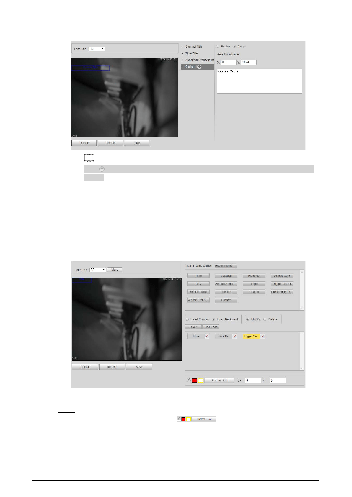
Figure 2-26 Custom title
Click to add more custom OSD information. The system supports up to 6 customized
regions.
Step 7 Click
Save
.
2.5.1.3.2 Original Picture OSD
You can set OSD information of pictures.
Procedure
Step 1 Select
Setting
>
ANPR
>
OSD Info
>
Original Picture OSD
.
Figure 2-27 Original picture OSD
Step 2 Move the title box to displayed location, or manually enter coordinate value into the X/Y
box on the lower-right corner.
Step 3 Configure the font size of the title next to
Font Size
.
Step 4 Set the color of OSD information in .
Step 5 Configure the OSD information separator.
1) Click
More
.
2) Select a separator type.
3) Click
OK
.

24
Step 6 Configure other OSD options.
Table 2-11 Snap OSD parameters description
Parameter Description
Insert Forward
Select one OSD option, click
Insert Forward
, and select other OSD options.
The new OSD options will be displayed before original OSD option.
Insert
Backward
Select one OSD option, click
Insert Backward
, and select other OSD options.
The new OSD option will be displayed after the original OSD option.
Modify
Click it, and all the OSD information status is displayed as except
Line
Feed
. Click to modify the prefix, suffix, content, and separator of
corresponding OSD option.
Delete
Click it, and all the selected OSD information status is displayed as , click
to delete corresponding OSD option.
Clear Delete all OSD information.
Line Feed
Line feed is used to separate different information into multiple lines. For
example, information 1 before a line feed is displayed on the first line, and
information 2 after the line feed is displayed on the second line.
Step 7 Click
Save
.
2.5.1.4 Configuring Cutout
2.5.1.4.1 Snapshot Cutout
Enable plate cutout function, and the system will cut out the recognized plate picture, and save it to
the storage path.
Procedure
Step 1 Select
Setting
>
ANPR
>
Cutout Config
>
Cutout Config
.
Figure 2-28 Snapshot cutout
Step 2 Select
Enable
to enable
Plate No.
and
Vehicle Body Cutout
.
Step 3 Click
Save
.
2.5.1.4.2 Plate Overlay
You can select whether to overlap the plate image onto the snapshot, and set the overlap position
and size.
Procedure
Step 1 Select
Setting
>
ANPR
>
Cutout Config
>
Plate Overlay
.
Step 2 Configure the parameters.
Figure 2-29 Plate overlay

25
Step 3 Click
Save
.
2.5.1.5 Setting Blocklist and Allowlist for Vehicles
2.5.1.5.1 Allowlist
Add vehicles into the allowlist and if the barrier control is set to
Open barrier by allowlist
, only
vehicles on the allowlist can pass. You can add up to 110,000 records.
Procedure
Step 1 Select
Setting
>
ANPR
>
Vehicle Blocklist/Allowlist
>
Allowlist
.
Step 2 Enter a plate number and then click
Search
.
If the plate is on the allowlist, its detailed information will be displayed.
Directly click
Search
to display all records on the allowlist.
Figure 2-30 Allowlist
Step 3 Click
Add
, and enter the information of a plate to add it into the allowlist.
Select
Add More
, and click
OK
to continue adding another plate.
Step 4 Click
Save
.
Step 5 Click
Browse
, and then click
Download
on the pop-up window to download the import
template.
Figure 2-31 Import
Step 6 Fill in the template and click
Browse
again.
Step 7 On the pop-up window, click
Browse
, select the template and then click
OK
.
All the plate information you have filled in the template are imported to the camera.
Step 8 Click
Export
.
Step 9 Select
Open
or
Close
to encrypt the exported allowlist or not, and then click
OK
.
Step 10 Select
Fuzzy Matching
, and then based on the actual situation, configure the rules.

26
Allow the system to misread some of the characters on the plate
is enabled by default.
Related Operations
●
Edit plate information: Click of the corresponding plate number searched, and edit the plate
number. Click
OK
.
●
Delete single plate number: Click of the corresponding plate number searched, and delete it
from the allowlist.
●
Delete plate number in batches: click
Clear All
, and then click
OK
in the pop-up window to
delete all the allowlist information.
●
Click
Clear Expired Data
to delete vehicles whose allowlist permissions have expired.
2.5.1.5.2 Blocklist
When a vehicle is on the blocklist, and the camera recognizes it, an alarm will be triggered. You can
add up to 110,000 records.
Procedure
Step 1 Select
Setting
>
ANPR
>
Vehicle Blocklist/Allowlist
>
Blocklist
.
Step 2 The procedures to search, import, and export of blocklist are similar to those of allowlist.
For details, see "2.5.1.5.1 Allowlist".
2.5.1.6 Configuring Barrier Control
2.5.1.6.1 Barrier Control
You can set the barrier control mode, and configure information of opening, and closing barrier.
Procedure
Step 1 Select
Setting
>
ANPR
>
Barrier Control
>
Barrier Control
.
Figure 2-32 Barrier control
Step 2 Configure the parameters.
Table 2-12 Parameter description
Parameter Description
Scheduled Barrier Always
Open
Select it, and enable the function of barrier always open. Configure
the period of barrier always open. The barrier will not close during
the defined period.
Enable Select it to enable barrier control, and configuration.

27
Parameter Description
Barrier Opening Method
Triggers alarm through different modes, and remotely controls the
barrier opening and close.
●
All Vehicles Open Barrier
: When the camera captures any
vehicle, it outputs an open barrier signal.
●
Licensed Vehicles (Camera)
: When the camera captures any
plate, it outputs an open barrier signal.
●
Open barrier by allowlist
: When the camera captures vehicles
that are on the allowlist or conform to fuzzy matching, it
outputs an open barrier signal.
●
Command (Platform)
: The camera outputs an open barrier
signal when it receives a command from the platform.
●
Click
Manually open barrier
or
Manually Close
to manually
control the barrier.
You can set barrier opening control to
Open barrier by allowlist
,
and
Command (Platform)
at the same time.
Open barrier by
allowlist
takes priority.
Barrier Opening Config
●
Alarm-out Port
: Alarm linkage output port. You can select any
one of the 3 ports.
●
Duration
: The duration that the barrier opening or closing
signal lasts.
Barrier Closing
Step 3 Click
Save
.
2.5.1.6.2 Remote Controller
You can connect the camera to a remote controller, and then you can use the remote controller to
control the camera.
Procedure
Step 1 Select
Setting
>
ANPR
>
Barrier Control
>
Remote Controller
.
Step 2 Configure
Warning Light
and
Duration
.
If
Warning Light
is selected, when you press the unlock button on the remote control, the
light on the camera will flash for the duration you configure.
Step 3 Click
Connect
, and then press the corresponding button the remote controller.
You must press the button in 10 seconds.
Step 4 (Option) To disconnect the remote controller, click
Disconnect
.
Step 5 Click
Save
.
2.5.1.7 Configuring RS-485 Settings
You can configure RS-485 serial protocol of external devices. After configuration, you can set related
parameters of the device on the web client of the camera.
Procedure
Step 1 Select
Setting
>
ANPR
>
RS-485 Settings
.
Step 2 Configure the parameters.
The camera supports multiple protocols.
●
DHRS

28
Figure 2-33 DHRS parameters
You can select external devices on the right side which support DHRS protocol.
●
Transparent
The third party platform can control the RS-485 output of the camera through RS-485
transparent transmission, and then you can connect external devices.
Trigger capture through transmitting capture command. To test the RS-485 transparent
transmission sending and receiving conditions, select
Send in hexadecimal
, and then
click
Open
on the right side of the
Information Received
section.
Figure 2-34 RS-485 Transparent transmission
●
Push Data through Serial Port
You can configure the serial port push information. The camera pushes the snapshots
to the third serial collection device through RS-485.
When there are two ports, serial port push protocol is unavailable for serial port 2.
Figure 2-35 Push data through serial port

29
Table 2-13 Parameter description
Parameter Description
Quick Config
Message Type
●
Select one or more items to be sent to the
third serial collection device.
●
Select the checkbox next to
Field Name
to
select all the fields.
Hover over the items to see their explanations.
Format Format of the items.
General Items selected by default.
Move Up/Down Click to move the item up or down.
General Config
Message Header
The tag head of data package. It is
aabb
by
default.
Message Trailer
The tag tail of data package. It is
aa55
by
default.
Encode Mode
Select encode type from
UTF-8
(default) and
GB2312
.
Verification Type
Select check mode from
Space
,
SUM Check
and
BCC Check
.
Step 3 Click
Save
.
2.5.1.8 Configuring RS-485 Peripheral
You can view the status of external devices connected to the camera through RS-485. Certain
configurations of external illuminators are also available.
Procedure
Step 1 Select
Setting
>
ANPR
>
RS485 Peripheral
.
Step 2 Click
External Device Status
, and you can see the detailed information of devices
connected to the camera.
Click
Refresh
can update the current status of external devices.
Step 3 Select
External Light
to configure the external light.
Figure 2-36 External light
1. Select
Yes
next to
Detect Status
to enable the status checking of the connected
continuous lights.
2. Set the
Working Mode
of the light, which can be
Always On
,
Always Off
,
By Time
and
Adaptive Brightness
.
●
When setting
Work Mode
to
By Time
, you need to configure the time schedule. For

30
details, see "2.5.1.9 Setting Time Schedule".
●
When setting
Work Mode
to
Adaptive Brightness
, you need to set the default
value for brightness.
Step 4 Set the
Light Brightness
of the light.
Step 5 Click
Save
.
2.5.1.9 Setting Time Schedule
This section introduces the method of setting time schedule, which can be used when setting the
work mode of external light and other situations.
Procedure
Step 1 Click
Setting
of a day to start setting the time schedule.
Figure 2-37 Time schedule
Step 2 Double-click each green line to clear the schedule for each day based on the actual
situation, and then you can set the schedule as needed.
1. Draw one or more periods on the timeline.
2. The drawn periods are synced to the table below, which shows all periods on one day.
3. You can manually change the time for each period.
Step 3 Click
OK
.
2.5.1.10 Configuring LED Screen
Connect the LED display with the camera through RS-485, and then you can configure the status,
display type, display color, action, speed, and more parameters of the LED.
Procedure
Step 1 Select
Setting
>
ANPR
>
LED Screen
.

31
Figure 2-38 LED screen
Step 2 Configure parameters.
Table 2-14 LED parameters description
Section Parameter Description
Device Status
Displays the status of the screen, such as work state,
ambient brightness, screen temperature and more.
Control Settings
Set the work mode for the screen.
●
Standalone Mode
: Display as configured, and not
controlled by any platforms.
●
Partially Managed Mode (Platform)
: Select this
to allow the platform to control part of the screen
information.
●
Managed Mode (Platform)
: Grant the platform
complete control over the display information on
the screen.
Screen Control
Set the color and action of display information when
vehicles pass under normal state. The screen will
display information as configured during the period
for either status.
Full Screen
Scrolling Speed The rolling speed of the information on the screen.
Passing Appears
On-screen for
The display duration of the passing vehicle
information on the screen.
Brightness
Adjustment
●
Ambient Adaptive
: The LED adjusts its
brightness according to the ambient brightness.
Set the
Augment Brightness
, the higher the
value, the bigger the brightness change.
●
Manual
: Manually adjust the LED brightness by
setting the
Intensity
.

32
Section Parameter Description
Self Check
●
Auto
: Set the time interval for the LED to do self-
check.
●
Never
: The LED does no self-check.
Step 3 Click
Save
.
2.5.1.11 Configuring Broadcast
You can configure the broadcast content for events, voice broadcast content when vehicles pass,
and the volume and video encoding settings for the broadcast.
2.5.1.11.1 Event Broadcast Settings
Configure the broadcast content when events are triggered.
Procedure
Step 1 Select
Setting
>
ANPR
>
Voice Broadcast Settings
>
Event Broadcast Settings
.
Step 2 Configure the parameters.
Figure 2-39 Event broadcast
Step 3 Select
Enable
to enable the function.
Step 4 (Optional) Click
Add Audio File
, and then follow the on-screen instructions to upload
audio files to be played when events are triggered.
Step 5 Select the checkbox under the
Enable
column to enable an event.
Step 6 Configure other parameters.
●
Play Mode
:
◇
File
: The audio file you selected will be played when the event is triggered.
◇
Combine
: The content in
Audio Content
will be played when the event is
triggered.
●
Audio Content
:

33
◇
When the
Play Mode
is set to
File
, select an audio file you uploaded.
◇
When the
Play Mode
is set to
Combine
, enter the content to be played when the
event is triggered.
[plate] and , are two special parameters in the content. [plate] will be replaced with
the plate number of the vehicle triggered the event, and , is used to pause for 0.5 s
between segments of the content. For example, the content is set to "[plate] is
loitering,Please exit the parking lost immediately", and the plate number of the
vehicle is AB12345, the broadcast content will be "AB12345 is loitering[puase for 0.5
s]Please exit the parking lot immediately".
●
Intervals(s)
and
Durations(s)
: The audio file or content will be continuously played for
the duration and at each interval you configured.
Step 7 Click
Save
.
2.5.1.11.2 Voice Broadcast Settings
Configure the broadcast content, and the camera will broadcast the content when vehicles pass.
Only certain devices support this function.
Procedure
Step 1 Select
Setting
>
ANPR
>
Voice Broadcast Settings
>
Voice Broadcast Settings
.
Step 2 Enable one or more options.
If the
Barrier Control
is set as
Order (Server)
and the voice broadcast is controlled by the
platform,
Parking Fee
,
Parking Duration
,
Expires at
,
Entry Time
and
Exit Time
will be
available.
Figure 2-40 Broadcast content
Step 3 Configure parameters.

34
Table 2-15 Parameters description
Parameter Description
Insert Forward Insert an option before the selected one on the display area.
Insert Backward Insert an option after the selected one on the display area.
Modify
Click next to the broadcast option to edit the prefix and suffix of
the option.
Delete Click next to the broadcast option to delete the option.
Clear Delete all broadcast options.
Step 4 Click
Save
.
2.5.1.11.3 Volume/Encoding Settings
Configure the volume for voice broadcast.
Only available for selected models.
Procedure
Step 1 Select
Setting
>
ANPR
>
Voice Broadcast Settings
>
Volume/Encoding Settings
.
Step 2 Configure the parameters.
Figure 2-41 Volume/Encoding
Table 2-16 Parameter description
Parameter Description
Input Volume The volume of the sound received by the camera.
Audio Output Type
Where the voice broadcast will be produced.
●
Camera Audio Output
: The voice broadcast will be played by
the device connected to the audio output port of the camera.
●
Camera Speaker
: The voice broadcast will be played by the
speaker of the camera.
Output Volume The volume of the voice broadcast.
Voice Speed The speed for the voice broadcast.
Step 3 Click
Save
.
2.5.1.12 Setting Device Test
2.5.1.12.1 Device Test
You can test the barrier opening and closing, capture, display content, voice broadcast, and
abnormal configuration modules to see if they work as configured. You can also export related

35
device information.
Procedure
Step 1 Select
Setting
>
ANPR
>
Device Test
>
Device Test
.
Figure 2-42 Device test
Step 2 Configure the parameters.
Table 2-17 Parameter description
Parameter Description
Test Barrier Opening/Closing
Click
Open
or
Close
to test whether the barrier responds
correctly.
Test Capture
Enter a plate number, click
Test
to trigger capture, and view the
snapshot in the
Live
page.
Test Screen Display
Enter some information, click
Test
, and view whether the
information is correctly displayed on the LED screen.
Test Voice Broadcast
Enter some information, click
Test
to check whether the device
plays the sound normally.
Voice broadcast is only available on select models.
Check for Abnormal Config
Click
Check
, and system checks abnormality automatically.
Export Device Info Select the information of the device, and export it in batches.
2.5.1.12.2 Capture Adjustment Information
You can overlay shield area box, vehicle body box, license plate box, vehicle body trajectory, plate
trajectory, and capture area on the snapshots to assist you in checking whether the snapshots are
taken as you require.
Procedure
Step 1 Select
Setting
>
ANPR
>
Device Test
>
Capture Adjustment Info
.
Step 2 Select the checkbox for
Displays rules and tracking info
, and then select the types of
information to be displayed.
Step 3 Click
Save
.

36
Step 4 Go to the
Live
page, and then click to manually capture a license plate. On the
snapshot, you can see the rules and tracking information you selected. If they do not meet
your requirements, you can adjust them by repeating the steps above.
2.5.1.12.3 Collection Log
The camera supports collecting operation logs to track errors.
Procedure
Step 1 Select
Setting
>
ANPR
>
Device Test
>
Collection Log
.
Step 2 Select the checkbox of
Enable
.
Figure 2-43 Collection log
Step 3 Select the type of log to collect.
Step 4 Click
Browse
to select a path to save the logs, and then click
Subscribe for logs
.
Step 5 Click
Save
.
2.5.2 Camera
You can configure image, video, and stream parameters.
2.5.2.1 Configuring Image Attributes
You can adjust the brightness, contrast, saturation of the video image, and set shutter parameters to
get clear videos and recordings that you want.
2.5.2.1.1 General
This section provides guidance on configuring parameters such as image brightness, contrast,
saturation, and hue.
Procedure
Step 1 Select
Setting
>
Camera
>
Image
>
General
.

37
Figure 2-44 General settings
Step 2 Configure the parameters.
Table 2-18 Parameters description
Parameter Description
Brightness
Adjust the overall image brightness. Change the value when the image is
too bright or too dark.
The bright and dark areas will have equal changes. The image becomes
blurry when the value is too high. The recommended value is from 40 to
60. The range is from 0 to 100.
It is 50 by default. The higher the value is, the brighter the image becomes.
Contrast
Change the value when the image brightness is proper but contrast is not
enough.
●
If the value is too big, the dark area is likely to become darker, and the
bright area is likely to be overexposed.
●
The picture might be blurry if the value is set too small. The
recommended value is from 40 to 60, and the range is from 0 to 100.
It is 50 by default. The higher the value is, the more obvious the contrast
between the bright area, and dark area will become.
Saturation
Adjust the color vividness, and will not influence the image overall
brightness.
●
The image becomes too flamboyant if the value is too big.
●
The image is not flamboyant enough if the value is too small. The
recommended value is from 40 to 60, and the range is from 0 to 100.
It is 50 by default. The higher the value is, the more flamboyant the image
becomes.
Gamma
Adjust the image brightness level. The higher the value, the brighter, and
blurry the image.
Fill Light Select IR or white light mode.
Day/Night
●
Color
: Applicable during the day, image shows in colors.
●
B/W
: Applicable during nights, the image is black and white.
●
Auto
: Set a value for brightness. When the brightness is higher or
lower than the value, the image shows in colors or black and white
respectively.
Only applicable when Fill Light is set to
IR Mode
.
Default
Environment
Brightness
Default value for brightness. You can drag the slider to adjust the value.
The higher the value, the brighter the video image.

38
Parameter Description
White Light
Select when the white light illuminator will work. If you select
Auto
, you
must specify the associated parameters that the illuminator will work
based on the values you defined.
Only applicable when Fill Light is set to
White Light
.
IR Light
●
Always Off
: Set the IR light to always on.
●
Always On
: Set the IR light to always off.
●
Day/Night
: Automatically turn on or off the IR light according to the
configured Day/Night mode.
Only applicable when Fill Light is set to
IR Mode
.
Light Brightness Set the illumination intensity when there are no vehicles passing.
Passing Light
Brightness
Set the illumination intensity when there are vehicles passing.
Step 3 Click
Save
.
2.5.2.1.2 Shutter
This section provides guidance on configuring camera shutter, including shutter mode, exposure
mode, gain mode, and scene mode.
Procedure
Step 1 Select
Setting
>
Camera
>
Image
>
Shutter
.
Step 2 Configure the parameters.
Table 2-19 Shutter parameters description
Parameter Description
3D NR
Video 3D NR
Select
Enable
to enable the function.
Video Spatial 3D
NR
Spatial video denoising. The higher the value, the fewer the noise.
Video Temporal
3D NR
Temporal video denoising. The higher the value, the fewer the flicker noise.
Image
Scene
You can change the scene, and adjust the sharpness of corresponding
scene. Scenes available:
Morning/Dusk
,
Day
, and
Night
.
Sharpness
You can set the sharpness of corresponding scene.
The higher the value, the clearer the image. But there will be noise if
sharpness is too high.
WDR
Select
On
to enable WDR (wide dynamic range), which helps provide clear
video images in bright and dark light.
Exposure
Iris Select the iris adjust mode from
Auto
, and
Manual
.
Mode
Select the way of adjusting exposure mode. You can select from
Manual
,
and
Auto
.

39
Parameter Description
Shutter
You can select the shutter value, or select
Customize
, and then set the
shutter range.
You need to set shutter when set
Mode
to
Manual
.
Shutter Scope
Set the time range for shutter.
You need to set shutter when
Customize
is set as
Shutter
.
Gain Scope
Set the value range for gain.
You need to set gain scope when set
Mode
to
Manual
.
WB
Mode Set a scene mode to adjust the image to its best status.
Step 3 Click
Save
.
2.5.2.1.3 Metering
This section provides guidance on setting the measure mode of metering zone.
Procedure
Step 1 Select
Setting
>
Camera
>
Image
>
Metering
.
Step 2 Configure the parameters.
Table 2-20 Parameter description
Parameter Description
Plate Light
When selecting
Enable
, you can turn
ON
or
OFF
backlighting
compensation, and frontlighting compensation according to scene
requirement, and then improve the image brightness in backlighting
situations.
Backlighting
Compensation
Frontlighting
Compensation
Metering Mode
●
Global Metering
: Measure the brightness of the whole image
area, and intelligently adjust the overall image brightness.
●
Partial Metering
: Measure the brightness of sensitive area, and
intelligently adjust the overall image brightness. If the measured
area becomes bright, then the whole area becomes dark, and
vice versa.
Step 3 Drag to select the measured area, and the system displays a yellow box. Drag the box to a
proper location.
Only need to draw measuring areas when setting
Metering Mode
to
Partial Metering
.
Step 4 Click
Save
.

40
2.5.2.2 Configuring Video Parameters
2.5.2.2.1 Video
You can set the video stream information.
Procedure
Step 1 Select
Setting
>
Camera
>
Video
>
Video Stream
.
Figure 2-45 Video stream
Step 2 Configure parameters.
Table 2-21 Parameters description
Parameter Description
Encode Mode Currently it only supports H.264M, H.264H, H.265, and MJPEG.
Resolution
Select the video resolution.
The resolution of sub stream cannot be greater than that of the main
stream.
Bit Rate Type
Include
VBR
, and
CBR
.
Image quality can only be set in VBR mode.
I Frame Interval
Frame or time interval between two I frames. The bigger the interval,
the smaller space taken by the decompressed video. The system
default is set twice as big as frame rate.
Watermark
Set the watermarks, which will be added into videos of the camera.
●
Select
Watermark
to enable the watermark adding.
●
Watermark String
is DigitalCCTV by default.
●
The watermark character can only consist of number, letter,
underline, and maximum length contains 85 characters.
Step 3 Click
Save
.
2.5.2.2.2 Snapshot
You can set the picture stream, including resolution, quality or picture size.
Procedure
Step 1 Select
Setting
>
Camera
>
Video
>
Snapshot
.
Step 2 Configure parameters.

41
Table 2-22 Parameters description
Parameter Description
Snapshot Type Only supports general snapshot currently.
Resolution The snapshot resolution.
Size It is in accordance with resolution value.
Quality Set the snapshot quality which includes 6 levels optional.
Size
Select a coding size, or select
Custom
to define the size (50–1024).
You can only select one between picture quality and picture coding size to
set the configuration.
Step 3 Click
Save
.
2.5.2.2.3 ROI
Set one or more interested areas in the image, and then the areas will be in the configured quality.
●
It supports up to 3 areas at the same time.
●
The image quality is displayed by level:
Worst, Worse, Bad, Good Better,
or
Best
.
●
Click
Clear
, and delete all the area boxes; Select one box, and then click
Delete
or right-click to
delete it.
Procedure
Step 1 Select
Setting
>
Camera
>
Video
>
ROI
.
Step 2 Draw a rectangle on the video image as the interested area.
You can adjust the image quality, clear all drawn areas or delete them one by one through
clicking
Delete
or right-click the area.
Step 3 Click
Save
.
2.5.3 Network Settings
You can set IP address, port, and other parameters.
2.5.3.1 Configuring TCP/IP
Configure the IP address of the camera, and DNS server so that the camera can connect with other
devices in the same network.
Some models support dual network port. Do not set them in the same network segment; otherwise
it might cause network error.
Procedure
Step 1 Select
Setting
>
Network Settings
>
TCP/IP
.
Step 2 Configure parameters based on the actual situation.
Step 3 Click
Save
.

42
2.5.3.2 Configuring Port
You can set the maximum number, and value of the ports.
Procedure
Step 1 Select
Setting
>
Network Settings
>
Connection
>
Port
.
Step 2 Set the maximum number of connections of the camera, and then configure each port.
Step 3 Click
Save
.
2.5.3.3 Configuring DDNS
Prerequisites
Confirm the server type which supports domain name analysis.
●
After enabling DDNS, your device information might be collected by the third party servers.
●
When a user registers and logs in to the DDNS website, you can view all the connected device
information.
Procedure
Step 1 Select
Setting
>
Network Settings
>
DDNS
.
Step 2 Select
Type
to enable DDNS, and then enter the information of the server.
Interval
means the update interval of the connection between the server and the device.
Step 3 Click
Save
.
2.5.3.4 Configuring Register
Through auto registration, when the device is connected from external network, the system will
report its current location to the server so that the client platform can access the device through
server.
Procedure
Step 1 Select
Setting
>
Network Settings
>
Register
.
Step 2 Check
On
to enable the function.
Step 3 Configure the parameters.
Table 2-23 Parameter description
Parameter Description
IP Address The IP address of the server on which the device registers.
Port The port of the server for auto registration.
Sub-Device ID
The device ID distributed by the server for auto registration. Make
sure that the ID is unique during auto registration.
Step 4 Click
Save
.
2.5.3.5 Configuring Multicast
When multiple users preview the video of the same device, unavailability might happen due to
network bandwidth restriction. You can fix it by setting up a multicast IP (224.0.0.0–239.255.255.255)

43
to access videos through the multicast protocol.
Procedure
Step 1 Select
Setting
>
Network Settings
>
Multicast
.
Step 2 Select the checkbox of
Enable
to enable the function.
Step 3 Enable main stream or sub stream based on the actual situation and set IP address and
port number.
Step 4 Click
Save
.
2.5.3.6 Configuring Email
Configure the email, and when alarms or abnormal events are triggered, an email will be sent to the
recipient server through SMTP server. The recipient can log in to the incoming mail server to receive
emails.
After enabling this function, there is a risk of data leakage that the system will send the device data
to the given server.
Procedure
Step 1 Select
Setting
>
Network Settings
>
Email
.
Step 2 Select the checkbox of
Enable
, and then configure the parameters.
Table 2-24 Parameter description
Parameter Description
SMTP Server
IP address of the outgoing mail server that complies with SMTP
protocol.
Port
Port number of the outgoing mail server complying with SMTP
protocol. It is 25 by default.
Anonymity
For servers supporting anonymous email, you can log in anonymously
without entering username, password, and sender information.
Username
Username and password of the sender mailbox.
Password
Sender Email address of the sender.
Encryption Type Select encryption type from
None
,
SSL
, and
TLS
.
Subject
You can enter no more than 63 characters in English letters, and
numbers.
Receiver Email address of the receiver. Supports 3 addresses at most.
Attachment Select the checkbox to add attachments in the email.
Test Email
Test whether the email function is normal. If the configuration is
correct, the email address of the receiver will receive the test email.
Save the email configuration before running the rest.
Step 3 Click
Save
.
2.5.3.7 Configuring SNMP
Set SNMP and connect to the camera through tools such as MIB Builder and MG-SOFT MIB Browser,

44
and then you can manage and monitor the camera on the tool.
Prerequisites
●
Install a software for monitoring and managing SNMP (Simple Network Management Protocol)
device.
●
Get the corresponding version of MIB file from technical support.
Procedure
Step 1 Select
Setting
>
Network Settings
>
SNMP
.
Step 2 Select the version of SNMP to enable it.
●
V1
: The device can only process the information of version 1.
●
V2
: The device can only process the information of version 2.
●
V3
: Set the username, password and authentication type to enable safety verification
when the server accesses the device.
Step 3 Enter the IP address of the computer on which the MIB software is installed as
Trap
Address
, and leave other parameters as default.
Step 4 Click
Save
, and then you can view the device configurations through MIB software.
2.5.3.8 Configuring 802.1x
Procedure
Step 1 Select
Setting
>
Network Settings
>
802.1x
.
Step 2 Select the checkbox of
Enable
, and then configure the parameters.
Table 2-25 Parameters description
Module Parameter Description
Common
Parameter
Authentication
Mode
●
PEAP
: Ordinarily uses TLS only to authenticate the
server to the client, and only the sever is required to
have a public key certificate.
●
EAP-TLS
: Provides mutual authentication of client to
server, and server to client. Both the client, and the
server must be assigned a digital certificate signed by
a CA (Certificate Authority) that they both trust.
CA Certificate
Select the
CA Certificate
checkbox, and then click
Browse
to import the CA certificate to verify whether the switch is
valid.
PEAP
Username For PEAP method, user authentication is performed by
using password-based credentials (username, and
password).
Password
EAP-TLS
Client
Certificate
Click
Browse
to import the client certificate, and private
key files for authentication.
Private Key
Step 3 Click
Save
.
2.5.3.9 Configuring PPPoE
Connect to the network through PPPoE, and the device can automatically obtain a dynamic IP on

45
public network.
Prerequisites
●
The device is connected to public network.
●
The username and password of PPPoE are provided.
●
Disable UPnP when using PPPoE.
●
You cannot change the device IP on web client after connected through PPPoE.
Procedure
Step 1 Select
Setting
>
Network Settings
>
PPPoE
.
Step 2 Select the checkbox of
Enable
, and then enter username and password.
Step 3 Click
Save
.
2.5.3.10 Configuring Platform Access
2.5.3.10.1 P2P
If enabled, the camera can be added to other platforms through P2P.
Procedure
Step 1 Select
Setting
>
Network Settings
>
Platform Access
>
P2P
.
Step 2 Select the checkbox of
Enable
.
Step 3 Click
Save
.
You can add the camera to other platforms using its serial number or by scanning its QR
code.
2.5.3.10.2 ONVIF
You can enable the Open Network Video Interface Forum (ONVIF) function to connect devices from
different manufactures to the same network.
ONVIF login authentication is enabled by default.
Procedure
Step 1 Select
Setting
>
Network Settings
>
Platform Access
>
ONVIF
.
Step 2 Select the
Open
.
Step 3 Click
Save
.
2.5.3.10.3 Info Push Platform
You can configure this parameter to push the captured vehicle violations information to the server.
●
All communications must be based on the HTTP protocol, conform to RFC2616 standards, and
support Digest authentication.
IO multiplexing must be available on the server.
●
Related business data must be in JSON format with ContentType: application/json;charset=UTF-8
as HTTP headers, which means the encoding method is UTF-8.

46
Procedure
Step 1 Select
Setting
>
Network Settings
>
Platform Access
>
Info Push Platform
.
Step 2 Select the checkbox of
Enable
, and then configure the parameters.
Figure 2-46 Info push platform
Table 2-26 Parameter description
Section Parameter Description
Basic
configuration
Keep Alive Interval
Update interval of the connection
between the server and the device.
Max Keep-alive Request
Set the maximum number of heartbeats
of the connection between the server and
the device. When the set number is
exceeded, the device has disconnected.
Data Acquisition
Data Type Select the data type to be uploaded.
Uploading Info
Select the specific information to be
uploaded.
Image Config
Filter Condition
Select whether to upload information of
unlicensed vehicles.
Upload Type
Select the type of pictures to be
uploaded.
Step 3 Click
Save
.
2.5.4 Event
This section provides guidance on configuring alarm, exception, defocus detection, and intelligent
analysis.

47
2.5.4.1 Alarm
2.5.4.1.1 Enabling Alarm-in and Alarm-out Ports
You can set several parameters of relay activation such as relay-in, period, anti-dither, and sensor
type. When an alarm is triggered, the system sends the alarm signal to external devices to trigger, for
example, buzz.
Procedure
Step 1 Select
Setting
>
Event
>
Alarm
>
Alarm
.
Step 2 Select the checkbox of
Enable
to enable alarm input for the current channel.
Step 3 Select alarm input channel.
Step 4 Click
Setting
next to
Period
to set the period of alarm input. For details, see "2.5.1.9
Setting Time Schedule".
Step 5 Configure other parameters.
Table 2-27 Parameter description
Parameter Description
Anti-dither
Enter anti-dither time (1 s–100 s). System will only record one when there are
multiple alarms during the defined time.
Sensor Type
Select relay-in type according to the connected alarm input device.
●
NO
: Low level valid.
●
NC
: High level valid.
Alarm-out
Port
Optocoupler output. Select the checkbox to activate corresponding alarm
output device when alarm occurs.
Duration The time that delays alarm when alarm occurs.
Step 6 Click
Save
.
2.5.4.1.2 Alarm-out Port
This function is used to check if the alarm-out port is working properly.
Procedure
Step 1 Select
Setting
>
Event
>
Alarm
>
Alarm-out Port
.
Step 2 Click
NO1
or
NO 2
.
Select the one or both that are connected to devices so that there is a response for you to
know if the port is working properly.
Step 3 Click
Trigger Mode
to send an alarm-out signal.
For example, the camera connects to a buzzer. When you click
Trigger Mode
, the buzzer
buzzes, meaning the alarm-out port works properly.
2.5.4.2 Abnormality
Set an alarm-out mode for different events. When an abnormality happens, the system triggers an
alarm.
Procedure
Step 1 Select
Setting
>
Event
>
Exception
.
Step 2 Select a type of event from SD card exception, network exception, invalid access, security
exception, and blocklist.

48
Step 3 (Optional) Select an event type.
You only need to select this for SD card and network exceptions.
Figure 2-47 No SD card for SD card exception
Step 4 Select the checkbox of
Enable
.
Step 5 Configure the parameters of each event.
Table 2-28 Parameters description
Parameter Description
Enable Select to enable the corresponding abnormality event.
Alarm-out Port
Select to enable the corresponding alarm output of abnormality event,
and select the corresponding port.
Post-alarm The alarm linkage keeps running for the defined time after alarm ends.
Original Image
Configure the storage available that triggers an abnormality alarm.
Only need to configure when setting
Event Type
to
Memory
insufficient
.
Original Image The original snapshot and license plate cutout image will be sent as
attachments in the email.
Only need to configure when selecting
Blocklist
.
Plate Cutout
Login Attempt
Configure the number of login attempts allowed. It ranges from 3–10
times.
Only need to configure when setting
Invalid Access
.
Send Email
The system sends an email to the defined email address when an alarm
is triggered. To set the email address, go to
Setting
>
Network
Settings
>
Email
.
Only need to configure when setting
Invalid Access
and
Blocklist
.
Step 6 Click
Save
.
2.5.4.3 Defocus Detection
When the video image is out of focus, this will trigger an alarm.
Procedure
Step 1 Select
Setting
>
Event
>
Defocus Detection
.
Step 2 Select the checkbox of
Enable
, and then click
Save
.

49
2.5.4.4 IVS
The camera supports detecting targets that are loitering or enter an off-limit area. You can configure
up to 4 rules.
Procedure
Step 1 Select
Setting
>
Event
>
IVS
.
There is one rule by default.
Step 2 Click
Draw Rule
, draw an area on the video image, right-click to complete drawing.
Step 3 (Optional) Use the target filter function to only detect targets with a certain size.
1) Select
Max Size
>
Draw Target
, and then click and hold on the video image to draw an
area.
You can drag any of its corners to adjust it.
2) Click
Min Size
, and then click and hold on the video image to draw an area.
You can also drag any of its corners to adjust it.
Only targets smaller than the maximum size, but bigger than the minimum size will be
detected.
Step 4 Configure other parameters.
Table 2-29 Parameter description
Parameter Description
Arm and Disarm Period
Mode
Configure when targets will be detected and trigger alarms. For
details, see "2.5.1.9 Setting Time Schedule".
Target Select the types of targets to trigger alarms.
Interval
The interval between each alarm to be triggered. For example, if you
set it to 200 s, with each alarm triggered, another alarm can only be
triggered after 200 s.
Duration
An alarm can only be triggered if a target is detected for as long as the
defined duration. For example, if you set it to 3 s, a loitering alarm will
only be triggered after a car has been loitering for 3 s or more.
Warning Light
If selected, the illuminator on the camera will flash for the duration you
defined when an alarm is triggered.
Duration
Send Email
The camera sends an email to the defined email address when an
alarm is triggered. To set the email address, go to
Setting
>
Network
Settings
>
Email
.
Linkage Snapshot If selected, the camera will take a snapshot when an alarm is triggered.
Step 5 Click to add more rules, and then repeat the previous steps to configure them.
You can configure up to 4 rules.
Step 6 Click
Save
.
2.5.5 Storage
This section provides guidance on setting associated information of storage, and record control.

50
2.5.5.1 Storage Spot Config
Set the locations for storing snapshots.
Procedure
Step 1 Select
Setting
>
Storage
>
Storage Spot Config
.
Step 2 Select a location to store snapshots.
●
Local Storage
: Stores the snapshots on the memory card.
●
FTP
: Stores the snapshots on the FTP server.
If you select both locations, a copy of each snapshot will be stored on both of them.
Step 3 Click
Save
.
2.5.5.2 Local Storage
Display the information on the local SD card. You can set hot swap, and format SD card.
Format the SD card before use.
Procedure
Step 1 Select
Setting
>
Storage
>
Local Storage
.
●
Select
Overwrite
or
Stop
from
Disk Full
, meaning overwrite the records or stop storing
new pictures or videos respectively when disk is full.
●
View the storage information of the card.
●
Click
Hot Swap
, and then you can pull out the SD card.
●
Click
Format
, and then you can format the SD card.
Figure 2-48 Local configuration parameter description
Step 2 Click
Save
.
2.5.5.3 FTP
FTP function can be enabled only when it is selected as destination path. When the network does
not work, you can save all the files to the internal SD card for emergency.
You can set picture name, and storage path. Click
Help…
to view the naming rule.
Procedure
Step 1 Select
Setting
>
Storage
>
FTP
.

51
Figure 2-49 FTP
Step 2 Configure the parameters.
Table 2-30 FTP configuration parameter description
Parameter Description
ANR
When the network disconnects or fails, snapshots will be stored in TF
card. After the network is restored, the snapshots will be uploaded from
the TF card to FTP or client.
Make sure that TF card is inserted in the camera; otherwise, the offline
transfer function cannot be enabled.
Picture Name
Settings
Set the naming rule of snapshots to be saved in FTP server. You can click
Help…
to view the naming rule, or click
Reset
to restore the default
naming rule.
Enable Enable FTP server storage.
Protocol
●
SFTP (Recommended)
: Secure File Transfer Protocol, a network
protocol allows file access, and transfer over a secure data stream.
●
FTP
: File Transfer Protocol, a network protocol implemented to
exchange files over a TCP/IP network. Anonymous user access is also
available through an FTP server.
Server IP The IP address of FTP server.
Encode Type
Refers to the encode mode of Chinese characters when naming pictures.
Two modes are available:
UTF-8
, and
GB2312
. After configuring
Server
IP
, and
Port
, click
test
to check whether the FTP server works.
Port The port number of FTP server.
Username
The username, and password of FTP server.
Password
Upload Picture Select the types of pictures to be uploaded to the FTP server.
Step 3 Click
Save
.

52
2.5.5.4 Platform Server
You can set the parameters of storing to client.
Procedure
Step 1 Select
Setting
>
Storage
>
Destination
>
Client
.
Step 2 Configure the parameters.
Table 2-31 Parameter description
Parameter Description
ANR
When network is disconnected or failed, you can store the picture into
local storage card, and it will automatically upload to platform server
after network resumes.
Type
Select connection type with platform server.
●
IP: Connect to platform server through IP address.
●
MAC: Connect to platform server through MAC address.
Server Select server, which includes
Server1
, and
Server2
.
Server IP
●
When the type is set to
IP
, you need to fill in IP address of the
server.
●
When the type is set to
MAC
, you need to fill in MAC address of
the server.
Step 3 Click
Save
.
2.5.5.5 Storage Path
This section provides guidance on configuring picture, record naming, and storage path.
Procedure
Step 1 Select
Setting
>
Storage
>
Destination
>
Save Path
.
Step 2 According to your actual requirements, set the name of picture, and storage path. Click
Help…
for more details.
Step 3 Set the root path of record, and snapshot as needed.
Step 4 Click
Save
.
2.5.6 System
You can configure general information, add user, restore to default settings, and configure import
and export files.
2.5.6.1 General
2.5.6.1.1 General Setup
This section provides guidance on configuring device SN, language, and video standard.
Procedure
Step 1 Select
Setting
>
System
>
General
>
General
.
Step 2 Configure the parameters.

53
Table 2-32 Parameters description
Parameter Description
Device Name The ID number of the camera. Supports English letters and numbers.
Device No. The code of the camera. It cannot be used as OSD information.
Language
The language displayed on web. The language will be automatically
switched after logging in to webpage again. Currently it only supports
English.
Video Standard
●
PAL
: Phase Alternating Line. Currently most countries around the
world (including most countries in Europe, Africa, Australia, and China)
adopt this standard.
●
NTSC
: National Television System Committee. The main countries
which adopt this standard include America, Canada, and Japan.
Device
Organization
The company information of the camera.
Device Location Set the location information for the snapshot that the camera takes.
Step 3 Click
Save
.
2.5.6.1.2 Date & Time
You can set date and time format, system time, DST (Daylight Saving Time) or NTP server, and more.
Procedure
Step 1 Select
Setting
>
System
>
General
>
Date&Time
.
Step 2 Configure the parameters.
Table 2-33 Parameter description
Parameter Description
Date Format Select date format.
Time Format Select 24h or 12h system.
Time Zone The time zone where the camera is located.
System Time
Set current system time of the camera. It becomes valid immediately
after setting.
Sync PC Synchronizes the time of the camera with the time on PC.
DST
Enable the function, and then set start time, and end time of DST
according to date or week.
NTP Select to enable the function of network time synchronization.
NTP Server Time server address.
Port Port number of time server.
Interval The synchronization interval between device and time server.
Step 3 Click
Save
.
2.5.6.2 Account
2.5.6.2.1 Account Management
The system supports configuring operation user of web. You need to configure user group before

54
configuring user account.
●
The user with
Account
control authority can also change the password of other users.
●
We recommend you give fewer authorities to normal users than premium users to make user
management convenient.
●
You cannot delete the user in login status.
You can add, delete or modify user.
Procedure
Step 1 Select
Setting
>
System
>
Account
>
Account
>
Username
.
Step 2 Click
Add User
.
Figure 2-50 Add a user
Step 3 Configure parameters.
Table 2-34 Add user parameters description
Parameter Description
Username
Username contains up to 15 characters, consisting of number, letter,
underline, and hyphen. It cannot be the same as the existed username.
Password Enter and confirm the new password.
●
The password must consist of 8–32 non-blank characters and
contain at least two types of the following characters: Uppercase,
lowercase, numbers, and special characters (excluding ' " ; : &).
●
Follow the password security prompt to set a secure password.
●
Password should be the same as
Confirm Password
.
Confirm Password
Group
Select the group to which new users belong. Each group has different
permissions.
Remarks Remarks of the user.
Operation Permission Select the permissions that you want assign to the user.

55
Parameter Description
Restricted Login Set the IP address that is restricted to log in, and the restriction time.
Step 4 Click
Save
.
Step 5 Select
Group
.
You can add new group, delete added group or modify group permission, and memo.
●
The system supports up to 8 user groups, and the default user groups are
admin
and
user
.
●
You can modify, and delete the added user group, but not the default user group.
Step 6 Click
Add Group
, and then enter the name of user group, and select permissions for the
group.
The group name can contain up to 15 characters, consisting of number, letter, underline,
and hyphen. It must be unique.
Step 7 Click
Save
.
Related Operations
After adding a user or user group, click to change the user or user group information; click
to delete the added user or user group.
Admin user/group cannot be deleted.
2.5.6.2.2 ONVIF User
You can add, delete, and modify ONVIF on the user management page.
Procedure
Step 1 Select
Setting
>
System
>
Account
>
Onvif User
.
Step 2 Click
Add User
.
Step 3 Configure the parameters. For details, see "2.5.6.2.1 Account Management".
Step 4 Click
Save
.
Related Operations
After adding a user, click to change user information; click to delete the added user.
The admin user cannot be deleted.
2.5.6.3 Security
2.5.6.3.1 System Service
Select to enable system services as needed.
Procedure
Step 1 Select
Setting
>
System
>
Security
>
System Service
.
Step 2 Select needed system service.

56
Table 2-35 Parameters description
Parameter Description
SSH
SSH (Secure Shell) implements data encrypted transmission, and
effectively avoid information leakage during remote management.
Multicast/Broadcast Search
●
Multicast
: It realizes point-to-multipoint network connection
between sender, and receiver.
●
Broadcast Search
: Broadcast data packet in IP subnet, all the
hosts in the subnet will receive these data packets.
Password Reset
When you forget the password of admin user, you can set new
password through password reset function.
Password Expires in
The password word will expire after the defined days have passed,
and then you must change the password.
CGI
CGI is the port between external application program and web
server.
ONVIF
Realizes network video framework agreement to make different
network video products interconnected.
Audio/Video Transmission
Encryption
Enable this function to encrypt streams transmitted through
private protocols.
RTSP over TLS
Enable this function to encrypt stream transmitted through
standard protocol.
We recommend you keep the function on.
Private Protocol
Authentication Mode
Keep the recommended
Security Mode
.
Step 3 Click
Save
.
2.5.6.3.2 HTTPS
On the
HTTPS
page, you can create a certificate or upload an authenticated certificate so that you
can log in to the webpage using HTTPS protocol. It can ensure security of communication data, and
provide guarantee for user information, and device safety through reliable, and stable technical
approach.
Prerequisites
●
For first-time use of HTTPS or after changing device IP address, you need to create server
certificate, and install root certificate.
●
After creating server certificate, and installing root certificate, if you replace the PC for logging in
to the webpage, you need to download, and install the root certificate again on the new PC or
copy the downloaded root certificate on the new PC, and install.
Procedure
Step 1 Create certificate or upload the authenticated certificate.
●
If you select
Create Certificate
, follow the steps below.
1. Select
Setting
>
System
>
Security
>
HTTPS
.

57
Figure 2-51 HTTPS
2. Click
Create
.
3. Enter the required information such as region, IP or domain name, and then click
Create
.
The entered
IP or Domain name
must be the same as the IP or domain name of the
camera.
4. Click
Install
under
Request Created
, and then click
Download
to download root
certificate.
The system pops up
Save As
dialog box, select storage path, and then click
Save
.
5. Double-click the RootCert.cer icon.
6. Click
Install Certificate…
.

58
Figure 2-52 Install certificate
7. Click
Next
.
The
Certificate Store
page is displayed. You can select
Automatically select the
certificate store based on the type of certificate
or
Place all certificates in
custom certificate store
.

59
Figure 2-53 Certificate store
8. Click
Next
.
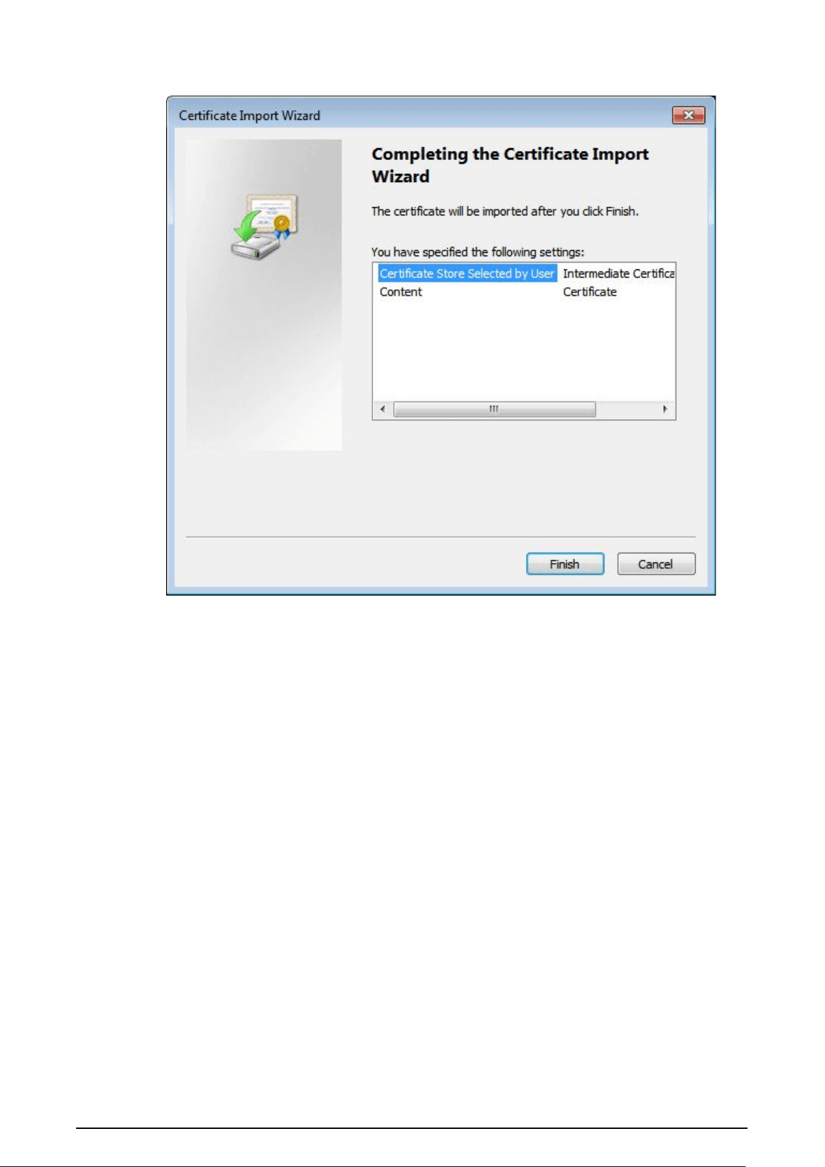
60
Figure 2-54 Completing certificate import wizard
9. Click
Finish
.

61
Figure 2-55 Security warning
10. Click
Yes
, and then click
OK
on the pop-up window.
●
If you select
install signed certificate
, follow the steps below.
1. Select
Setting
>
System
>
Security
>
HTTPS
.
2. Click
Create
.
3. Enter the required information such as region, IP or domain name, and then click
Create
.
The entered
IP or Domain name
must be the same as the IP or domain name of the
camera.
4. Select the checkbox of
Enable
, and
Compatible with TLSv1.1, and earlier
versions
.
5. Click
Browse
to upload the signed certificate, and certificate key, and then click
Upload
.
6. To install the root certificate, follow sub step 4 to 10 in Step 1.
Step 2 Log in to the camera using HTTPS protocol.
1. Enter https://xx.xx.xx.xx in the browser.
xx.xx.xx.xx is the device IP address or domain name.
2. Enter the username, and password to log in to the camera.
The browser will prompt certificate error if certificate is not installed.

62
2.5.6.3.3 Firewall
Set the security rules to protect your camera.
Procedure
Step 1 Select
Setting
>
System
>
Security
>
Firewall
.
Step 2 Select a firewall type.
●
Network Access
: Add the IP address to allowlist or blocklist to allow or restrict it to
access corresponding ports of the device.
●
PING Prohibited
: IP address of your camera is prohibited from ping. This helps prevent
attempt of accessing your network system without permission.
●
Anti Half Connection
: Prevents half-open SYN attacks.
Step 3 Select the checkbox of
Enable
, and then click
Save
.
2.5.6.4 Default Settings
You can restore the device to default settings or factory defaults.
Select
Setting
>
System
>
Default
, and then select
Default
or
Factory Default
as needed.
●
Default
: Restore your settings to default value. In this case, network IP address information of the
camera will not restore to default settings.
●
Factory Default
: Restore the system to factory default settings. In this case, the camera will
restart, and you need to initialize the camera before any further operation.
2.5.6.5 Import/Export
Export the system configuration file to back up the system configuration; import system
configuration file to make quick configuration or recover system configuration.
Procedure
Step 1 Select
Setting
>
System
>
Import/Export
.
Step 2 Click
Config Import
or
Config Export
.
●
Config Import
: Import the local system configuration file to the system.
●
Config Export
: Export associated configuration to local, and save as file whose suffix
is .backup.
Step 3 Select a path to save the file.
Step 4 Click
Open
or
Save
, and view import and export result on the webpage.
2.5.6.6 System Maintenance
You can set the time of auto restart, and automatically delete old files.
Procedure
Step 1 Select
Setting
>
System
>
Maintenance
.
Step 2 Configure the parameters.
Table 2-36 Auto maintain parameter description
Parameter Description
Auto Restart
●
Select
Auto Reboot
, and then set the restart period, and time.
●
The system will automatically restart within the defined period
and time.

63
Parameter Description
Delete Expired Files
Configure which files to be deleted automatically. For example, the
parameter is set to 2 days ago, then all files generated 2 days ago will
be deleted automatically.
Restart Manually restart the camera.
Step 3 Click
Save
.
Step 4 Click
Emergency Maintenance
, and then select the checkbox of
Enable
to enable
emergency maintenance of the camera.
Step 5 Click
Save
.
2.5.6.7 Update
Update the software of the camera online or through an update file.
●
Update using the wrong program might result in the camera not working properly.
●
During update, do not disconnect the camera from power or network, or restart it or close the
webpage.
Procedure
Step 1 Select
Setting
>
System
>
Update
.
Step 2 Update the camera.
●
Using an update file.
1. Click
Browse
, and then select the update file in .bin format.
2. Click
Update
.
●
Manual update.
1. Click
Manual Check
to manually check the system version.
2. Follow the onscreen instruction to update the camera.
Step 3 (Optional) Select the
Auto Check for Updates
, and then click
OK
.
The camera will regularly check for updates, and automatically update when available.
2.5.7 System Info
You can view system information such as version, user, and log, and more.
2.5.7.1 Version
You can view the version information of the camera.
Select
Setting
>
System Info
>
Version
.

64
●
Versions of different devices might vary depending on the actual webpage.
●
Algorithm recognition is available when algorithm is authorized (when the icon is displayed in
green). If algorithm is not authorized, the camera will not be able to recognize vehicle series,
model, and logo. License plate recognition is always supported.
2.5.7.2 Log
2.5.7.2.1 System Log
You can view log information such as system, configuration, data, event, record and user
management.
The earliest log records will be overwritten when the number of log records reaches 1024.
Procedure
Step 1 Select
Setting
>
System Info
>
Log
>
Log
.
Step 2 Enter
Start Time
, and
End Time
, and then select log type.
Step 3 Click
Search
.
Figure 2-56 Log
Step 4 Click a searching result to view its details.
Step 5 (Optional) Click Backup, and then follow the on-screen instructions to export the search
results to your computer.
To protect the search results you exported, you can encrypt it with a password. Select
Encrypt Log Backup
, enter a password, and then click
Backup
.
2.5.7.2.2 Remote log
You can save your important logs to a log server. This helps provide important clues to the source of
security incidents. A log server must be deployed in advance by a professional or system
administrator.
Procedure
Step 1 Select
Setting
>
System
>
Log
>
Remote Log
.

65
Step 2 Select the checkbox of
Enable
.
Step 3 Configure the IP address, port, and device number.
Step 4 Click
Save
.
2.5.7.3 Online User
Select
Setting
>
System
>
Online User
to view the information of all the online users.
Click
Refresh
to view the latest status.
2.5.7.4 Running Status
Select
Setting
>
System
>
Running Status
to view the system running status.
Click
Refresh
to get the latest details.
2.6 Alarm
Click the
Alarm
tab, and then you can select alarm types, operations, and alarm tones.
Table 2-37 Alarm parameters description
Type Parameter Description
Alarm Type
Disk Full
An alarm is triggered when storage card is
full.
Disk Error
An alarm is triggered when storage card fault
occurs.
External Alarm
It generates alarm through peripheral device
when alarm is triggered.
No SD Card
An alarm is triggered when there is no storage
card.
Vehicle Blocklist
An alarm is triggered when the blocklist
vehicle appears.
Invalid Access
An alarm is triggered when the times of login
password error reach the max value.
Security Exception
An alarm is triggered when there is security
exception.
Operation Subscribe Alarm You will be informed when an alarm occurs.
Alarm Tone
Play Alarm Tone
It generates alarm prompt tone when alarm
occurs. Alarm tone supports customized
settings.
Tone Path The path of customized alarm tone.
2.7 Logout
Click
Logout
to log out of the webpage.

66
3 FAQ
Question Solution
Device error, unable to start or
operate normally
Press and hold the Reset button for 5 seconds to restore the
camera to factory default settings.
SD card hot swapping
Stop recording, and image capturing, and then wait for at least
15 seconds before removing the SD card. This helps ensure
data integrity, and avoid losing all the data of the card.
SD card read/write limit
Do not set the SD card as the storage media of pre-set
recording. It might reduce the SD card duration.
SD card cannot be used as
storage media
When the SD card hibernates or its capacity is null, format the
card through web first.
Network upgrade failed
Check whether the right upgrade program (such as version,
compatibility) is used.
Recommended SD card
We recommend you use SD card of 16 GB or larger. This helps
avoid data loss arising from insufficient capacity.
You can use a card of 16 GB, 32 GB, 64 GB, and 128 GB.
Failed to pop up the
installation dialog box of web
control webrec.cab
Set the security level of IE browser as
Low
, and
Active Plug-in,
and Control
is set as
Enable
.

67
Appendix 1 Cybersecurity Recommendations
Mandatory actions to be taken for basic device network security:
1.
Use Strong Passwords
Please refer to the following suggestions to set passwords:
●
The length should not be less than 8 characters.
●
Include at least two types of characters; character types include upper and lower case letters,
numbers and symbols.
●
Do not contain the account name or the account name in reverse order.
●
Do not use continuous characters, such as 123, abc, etc.
●
Do not use overlapped characters, such as 111, aaa, etc.
2.
Update Firmware and Client Software in Time
●
According to the standard procedure in Tech-industry, we recommend to keep your device
(such as NVR, DVR, IP camera, etc.) firmware up-to-date to ensure the system is equipped with
the latest security patches and fixes. When the device is connected to the public network, it is
recommended to enable the“auto-check for updates” function to obtain timely information
of firmware updates released by the manufacturer.
●
We suggest that you download and use the latest version of client software.
"Nice to have" recommendations to improve your device network security:
1.
Physical Protection
We suggest that you perform physical protection to device, especially storage devices. For
example, place the device in a special computer room and cabinet, and implement well-done
access control permission and key management to prevent unauthorized personnel from
carrying out physical contacts such as damaging hardware, unauthorized connection of
removable device (such as USB flash disk, serial port), etc.
2.
Change Passwords Regularly
We suggest that you change passwords regularly to reduce the risk of being guessed or cracked.
3.
Set and Update Passwords Reset Information Timely
The device supports password reset function. Please set up related information for password
reset in time, including the end user’s mailbox and password protection questions. If the
information changes, please modify it in time. When setting password protection questions, it is
suggested not to use those that can be easily guessed.
4.
Enable Account Lock
The account lock feature is enabled by default, and we recommend you to keep it on to
guarantee the account security. If an attacker attempts to log in with the wrong password several
times, the corresponding account and the source IP address will be locked.
5.
Change Default HTTP and Other Service Ports
We suggest you to change default HTTP and other service ports into any set of numbers between
1024–65535, reducing the risk of outsiders being able to guess which ports you are using.
6.
Enable HTTPS
We suggest you to enable HTTPS, so that you visit Web service through a secure communication
channel.
7.
MAC Address Binding
We recommend you to bind the IP and MAC address of the gateway to the device, thus reducing
the risk of ARP spoofing.
8.
Assign Accounts and Privileges Reasonably
According to business and management requirements, reasonably add users and assign a

68
minimum set of permissions to them.
9.
Disable Unnecessary Services and Choose Secure Modes
If not needed, it is recommended to turn off some services such as SNMP, SMTP, UPnP, etc., to
reduce risks.
If necessary, it is highly recommended that you use safe modes, including but not limited to the
following services:
●
SNMP: Choose SNMP v3, and set up strong encryption passwords and authentication
passwords.
●
SMTP: Choose TLS to access mailbox server.
●
FTP: Choose SFTP, and set up strong passwords.
●
AP hotspot: Choose WPA2-PSK encryption mode, and set up strong passwords.
10.
Audio and Video Encrypted Transmission
If your audio and video data contents are very important or sensitive, we recommend that you
use encrypted transmission function, to reduce the risk of audio and video data being stolen
during transmission.
Reminder: encrypted transmission will cause some loss in transmission efficiency.
11.
Secure Auditing
●
Check online users: we suggest that you check online users regularly to see if the device is
logged in without authorization.
●
Check device log: By viewing the logs, you can know the IP addresses that were used to log in
to your devices and their key operations.
12.
Network Log
Due to the limited storage capacity of the device, the stored log is limited. If you need to save the
log for a long time, it is recommended that you enable the network log function to ensure that
the critical logs are synchronized to the network log server for tracing.
13.
Construct a Safe Network Environment
In order to better ensure the safety of device and reduce potential cyber risks, we recommend:
●
Disable the port mapping function of the router to avoid direct access to the intranet devices
from external network.
●
The network should be partitioned and isolated according to the actual network needs. If
there are no communication requirements between two sub networks, it is suggested to use
VLAN, network GAP and other technologies to partition the network, so as to achieve the
network isolation effect.
●
Establish the 802.1x access authentication system to reduce the risk of unauthorized access to
private networks.
●
Enable IP/MAC address filtering function to limit the range of hosts allowed to access the
device.