
- 20 -
User Manual
RANGE HOOD
Please read the following safety information carefully before installing and/or using this appliance.
We recommend that you keep this manual for future use and/or in case of transfer of ownership
of the range hood
JQG7505/JQG7505-W/JQG9006/JQG9006-W

- 23 -
Thank you!
Dear User, thank you for purchasing the Fotile
Range Hood. At Fotile, we manufacture exquisite
appliances that are expertly crafted with the finest
materials. Before using the Fotile Range Hood,
please take some time to read through this Product
Manual (manual). It will familiarize you with important
safety, operation and maintenance instructions, as
well as help maximize your culinary experience.
Before using the Fotile Range Hood, you must
follow the instructions, as specified in this manual.
Any damage resulting from the improper operation
and/or maintenance of the appliance may result
in the loss of warranty. The warranty will become
invalid, and your warranty application, whether direct
or indirect, will not be accepted by authorized service
center of Fotile. If you require warranty or post-
warranty after-sale service, please contact the local
authorized service center of Fotile nearest you.
Your satisfaction with the Fotile brand is
important to us. Our after-sales service centers
provide assistance in resolving issues with Fotile
appliances.
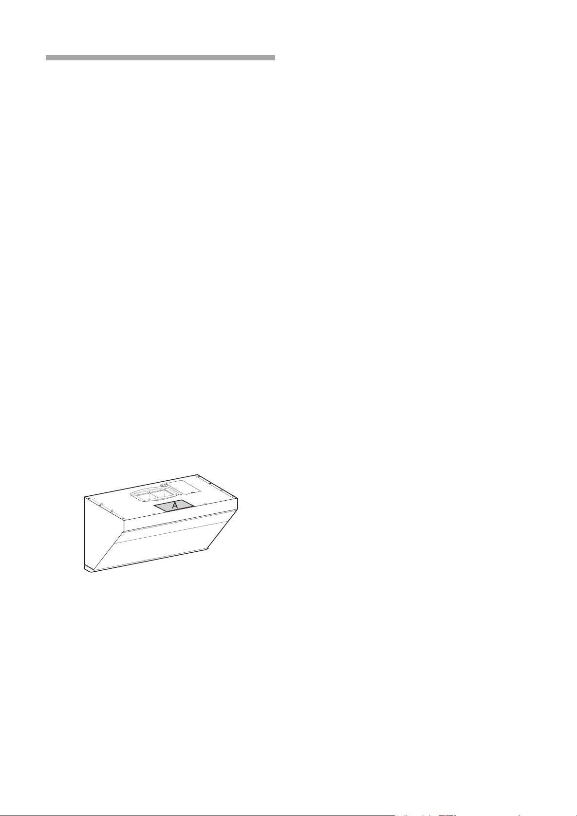
Product model and serial number on the plaque
are required if you need services.
Position of plaque can be referred to in figure
A as follows(The following diagrams are those of
basic models(JQG7505), for those derivative models
please refer to these diagrams of basic models.)
Contents
1 Safety Information .................................. 24
2 Operation .............................................. 27
2.1 Product Information ......................... 27
2.2 Operation ........................................ 28
3 Cleaning and Maintenance ................... 29
4 FAQ ....................................................... 32
5 Service Information ............................... 32
6 Installation .............................................. 32
6.1 Installation Instructions ................... 33
6.2 Product dimensions ......................... 34
6.3 List of Accessories .......................... 34
6.4 Installation Tools............................... 36
6.5 Installation Procedure ...................... 36
6.6 Test Run After Installation ................ 43
In order to ensure the safe and efficient use of
Fotile appliances, please take note of the following
types of highlighted information that will be outlined
throughout this manual:
IMPORTANT NOTE
highlights information that is
particularly important.
CAUTION
signals a situation where minor injury or
product damage may occur if instructions are not followed.
WARNING
states a specic hazard that may cause
serious injury or death if precautions are not followed.
Product features and specifications are subject to
change, at any time, without notice and may be
different from those in this material. Please visit our
website for the most up-to-date information.
FOTILE YouTube
FOTILE America LLC
FOTILE Toronto Flagship Store
* Address
:
6 Campus Dr, Suite 210, Parsippany, NJ 07054
* Toll Free
:
888-315-0366
* Website
:
us.fotileglobal.com
* Service Mail
:
* Address
:
8365 Woodbine Ave
,
Markham, L3R2P4
* Toll Free
:
844-315-0315
* Website
:
ca.fotileglobal.com
* Service Mail
:
US WeChat Service
Canada WeChat Service
Canada Wechat
Ofcial Account

- 23 -
Thank you!
Dear User, thank you for purchasing the Fotile
Range Hood. At Fotile, we manufacture exquisite
appliances that are expertly crafted with the finest
materials. Before using the Fotile Range Hood,
please take some time to read through this Product
Manual (manual). It will familiarize you with important
safety, operation and maintenance instructions, as
well as help maximize your culinary experience.
Before using the Fotile Range Hood, you must
follow the instructions, as specified in this manual.
Any damage resulting from the improper operation
and/or maintenance of the appliance may result
in the loss of warranty. The warranty will become
invalid, and your warranty application, whether direct
or indirect, will not be accepted by authorized service
center of Fotile. If you require warranty or post-
warranty after-sale service, please contact the local
authorized service center of Fotile nearest you.
Your satisfaction with the Fotile brand is
important to us. Our after-sales service centers
provide assistance in resolving issues with Fotile
appliances.
Product model and serial number on the plaque
are required if you need services.
Position of plaque can be referred to in figure
A as follows(The following diagrams are those of
basic models(JQG7505), for those derivative models
please refer to these diagrams of basic models.)
Contents
1 Safety Information .................................. 24
2 Operation .............................................. 27
2.1 Product Information ......................... 27
2.2 Operation ........................................ 28
3 Cleaning and Maintenance ................... 29
4 FAQ ....................................................... 32
5 Service Information ............................... 32
6 Installation .............................................. 32
6.1 Installation Instructions ................... 33
6.2 Product dimensions ......................... 34
6.3 List of Accessories .......................... 34
6.4 Installation Tools............................... 36
6.5 Installation Procedure ...................... 36
6.6 Test Run After Installation ................ 43
In order to ensure the safe and efficient use of
Fotile appliances, please take note of the following
types of highlighted information that will be outlined
throughout this manual:
IMPORTANT NOTE
highlights information that is
particularly important.
CAUTION
signals a situation where minor injury or
product damage may occur if instructions are not followed.
WARNING
states a specic hazard that may cause
serious injury or death if precautions are not followed.
Product features and specifications are subject to
change, at any time, without notice and may be
different from those in this material. Please visit our
website for the most up-to-date information.
FOTILE YouTube
FOTILE America LLC
FOTILE Toronto Flagship Store
* Address
:
6 Campus Dr, Suite 210, Parsippany, NJ 07054
* Toll Free
:
888-315-0366
* Website
:
us.fotileglobal.com
* Service Mail
:
* Address
:
8365 Woodbine Ave
,
Markham, L3R2P4
* Toll Free
:
844-315-0315
* Website
:
ca.fotileglobal.com
* Service Mail
:
US WeChat Service
Canada WeChat Service
Canada Wechat
Ofcial Account

- 24 - - 25 -
will prevail, and installation personnel must
conform to these requirements.
• The operating temperature of the range hood
should not exceed 104
℉
(40
℃
).
• Please do not place anything on top of the
product. Anything placed on top may fall off or
incline. For example, if you place seasoning
bottles on top, the inclination may cause
liquid to flow inside the product, resulting in
damaged electrified components and therefore
unnecessary risks. Our company will not bear
the responsibility for free repair in case of
product damage due to the above reason.
• Clean the Grease Cup frequently to prevent
overow. The resulting grease is inedible! Please
do not place ammable materials in the oil cup,
such as plastic wrap, paper towels, etc.
• When cutting or drilling into the wall or ceiling,
be careful not to damage electrical wiring,
water pipes, gas lines, or other hidden utilities.
• Adhere to the heating equipment manufacturer’s
guidelines and safety standards, such as
those published by the National Fire Protection
Association (NFPA), the American Society for
Heating, Refrigeration and Air Conditioning
Engineers (ASHRAE) and the local code
authorities. Meanwhile, conform to the safety
standards issued by such administrative
departments as re department.
• When gas burners are in operation without any
cookware placed on them, they can build up
a lot of heat. A ventilation appliance installed
above the cooker may become damaged or
catch re. Only operate the gas burners with
cookware on them.
• Adhere to the voltage and frequency settings
listed in this manual to avoid possible
damages to the range hood.
• Please use standard accessories provided by
our company to prevent the range hood from
falling down accidentally. The hole drilled in
the wall should precisely match the size of the
expansion pipe, otherwise, the range hood
may loose and fall down.
• Tampered glass is applied to the products of
the company and the tampering treatment
of the glass determines the extremely little
possibility of spontaneous explosion. If the
occurrence of spontaneous explosion is not
due to improper use, our company promises
free replacement of the accessories. The
possibility of tempered glass breaking can
be significantly increased in the following
situations, which should be avoided: For
instance, hitting the glass, especially the
corners of the glass, with cooking utensils
or other hard objects; The glass is impacted
when you open a cabinet door around the
Range Hood; Put the glass in an extremely hot
or cold environment or an environment where
heat and cold are excessively alternated.
• Unauthorized modication of this product can
lead to risks.
Warning:
Risk of Electric Shock
A defective appliance may cause electric shock.
Never switch on a defective appliance. Unplug the
appliance from the mains or switch off the circuit
breaker in the fuse box in case of problems, and
contact our authorized service center.
• The range hood should be connected to a
standard power socket with safe grounding.
Midway connection, prolonged electric line or
multi-socket wiring may cause electric shock,
overheating and, in some cases, result in
a fire. Installation of the range hood should
be performed by professional electricians in
strict accordance with electricity standards
and regulations of the local area. Before
connecting the rod, turn off the power source
and take appropriate measures to prevent
auto closing of the power switch.
• In order to prevent electric shock and/or other
bodily injuries to persons, do not exceed 120V
AC input.
• Do not install the range hood in a bathroom
and/or a humid area, as this will significantly
increase the risk of electric shock.
• If a wire is damaged or defective, contact an
authorized service provider or a qualied technician
(provided by Fotile) to replace the wire.
• Do not change, stretch, knot, pressure or
squeeze the wire as any resulting damage can
In order to prevent accidental damage to the
Fotile Range Hood and/or bodily injuries as a
result of its operation, please read the following
safety informationinstalling and/or using this
appliance. Following the instructions carefully
will significantly reduce the risk of fire, electric
shock and/or bodily injuries to persons. We
recommend that you keep this manual for future
use and/or in case of transfer of ownership of
the range hood.
Important Note:
• This appliance is intended for indoor home
cooking only; it cannot be used for outdoor
cooking. Please use this product only
according to the manufacturer’s instructions.
Fotile assumes no responsibility if you use
it in special environment. Please contact
a Fotile authorized service center if you
encounter any problem.
• Check the appliance for damage after
unpacking it. If you detect any obvious
damage to the product, do not proceed with
the installation. Please contact our authorized
service center immediately.
• Avoid placing gypsum powder, construction dust,
etc. within close proximity of the range hood.
• Operate the range hood only in the manner
outlined in this product manual.
• When operating the range hood, do not leave
the appliance unattended. If you have any
questions and/or concerns, please contact our
authorized service center.
• Operate, clean and maintain the range hood in
accordance to the instructions outlined in this manual.
• Clean the metal grease lter according to the
instructions.
• The range hood’s motor has a thermal overload
function, which automatically turns off the motor
when it overheats. Once the motor cools down,
the range hood will automatically restart. If the
motor, continually turns off and restarts, please
contact our authorized service center.
• If the range hood has not been in operation for an
extended period of time, unplug the appliance.
• Please make sure correct installation and
maintenance of the appliance. Installation
work and electrical wiring must be done by
qualified person(s), in accordance with all
applicable codes and standards, including re-
rated construction codes and standards. The
installation personnel should be responsible
for normal operation of the appliance at the
installed position.
• When operating the range hood in exhaust
mode, ensure to install the damper along with
the hood.
• For general exhausting only. Do not use this
range hood to exhaust hazardous and /or
explosive materials or gas.
• The product itself is nonammable.
• In order to reduce the risk of fire, all
exhaust pipes, flues and devices should be
nonammable. Use only metal duct cover and
metal duct pipes. Never cover the hood with
ammable plastic lm or paper.
• Services guaranteed under warranty must be
performed by Fotile certified service provider
or personnel.The warranty is not effective
for products removed for repair without
authorization.
• Please read the specication label on the range
hood for further information and requirements.
• Please install a supplementary air device if
you install the high-power Range Hood in an
airtight room. Due to the configuration of the
Fotile Range Hood, it is recommended for
users with an airtight new house to install a
supplementary air device. Please comply with
relevant regulations to install corresponding
supplementary air device if there are relevant
regulations in your state or region.
• This product is only used in USA and Canada.
• This product is for use in the U.S. and Canada
only.
Caution:
• When applicable local regulations comprise
more restrictive installation and/or certification
requirements, the aforementioned requirements
SAFETY INFORMATION

- 26 - - 27 -
where it started.
• The re department is being called.
• You can ght the re with your back to an exit
Risk of Injury
• This appliance is not intended for use by
persons (including children) with reduced
physical, sensory or mental capabilities, or
lack of experience and knowledge, unless they
have been given supervision or instruction
concerning use of the appliance by a person
responsible for their safety. Children should be
supervised to ensure that they do not play with
the appliance.
• The range hood may have sharp edges. Be
careful to avoid cuts and abrasions during
installation and cleaning. Do wear qualified
protective gloves.
• The accessible parts become very hot when
in operation. Never touch hot parts. Keep
children at a safe distance.
• Do not touch lamps during or soon after
operation. Burns may occur.
• Do not insert your limbs and/or foreign objects
into the impeller while the range hood is in
operation, as that action might cause injury.
• This appliance is not intended for operation with
an external clock timer or a remote control.
• Incorrect repairs are dangerous. Repairs
may only be carried out and damaged power
cables replaced by one of our trained after-
sales technicians..
• If any abnormalities and/or defects occur while
operating the range hood, immediately turn off
the appliance and unplug the appliance from
the mains or switch off the circuit breaker in
the fuse box. Then, contact our authorized
service center. Abnormal operation and
defects may cause hazardous situations, such
as electric shocks and res.
• This product contains chemicals known to the
State of California to cause cancer, and birth
defects or other reproductive harm. For more
information, please go to: www.P65Warnings.
ca.gov
Risk of Suffocation:
• Packaging material is dangerous to children.
Never allow children to play with packaging
material, which may cause suffocation.
Keep all packing material out of proximity to
children. Please remember that packaging
materials should not be treated as toys.
Risk of Death:
• Risk of poisoning from ue gases that are drawn
back in.
• Always ensure adequate fresh air in the room if
the appliance is being operated in exhaust air
mode at the same time as room air-dependent
heat-producing appliance is being operated.
Exhaust gases through the flue (chimney) of
fuel burning equipment to prevent back drafting.
• Fotile is not responsible for injuries caused by
improper and/or incorrect operation of the range hood.
OPERATION
Warning
1. Do not use excessive force to press buttons
on the control panel.
2. Turn off gas burners without any cookware
placed on them.
3. Do not disassemble the appliance with power
on and/or without complying with instructions.
4. Clean the Grease Cup frequently to prevent
overow and a potential re.
5. Disassembly and/or servicing of the range hood
must be performed by qualied technicians.
6. Do not let the stove re burn the range hood directly.
Product Information
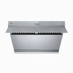
Model JQG7505/JQG7505-W
Produce size
L*D*H
29 7/8 × 18 7/16 × 17 7/16 "
(758 × 467 × 442 mm)
Net weight 63.9 lbs(29Kg)
Voltage/Frequency 120V/60Hz
Rated power input
of the range hood
210 W (light power included 3W × 2 )
CFM(HVI)
Super-high-setting
600
High-setting 540
Medium-setting 420
Low-setting 230
Noise
Super-high-setting
56dB(A)(7.2Sones)
High-setting 53dB(A)(6.2Sones)
Medium-setting 48dB(A)(3.9Sones)
Low-setting 38.5dB(A)(1.2Sones)
result in electrical and/or re hazards.
• Prevent water from coming into contact with
the range hood’s electrical components, such
as the motor, switch and connector. Do not
wash the appliance with water. Do not use the
appliance if it is wet, as electric leakage and/
or electric shock may occur.
• Do not attempt to change the range hood’s
internal wiring system. Improper modications
and/or repairs to the internal wiring can result
in bodily injuries to persons, electric shock
and/or a re.
• In order to avoid electric shock, remember to
turn off the appliance’s power source before
installation, cleaning and/or maintenance
service.
• Avoid using high-pressure detergents and/or
steam cleaners on the appliance, as they may
result in electric shock.
• Do not touch the plug or switch with wet hands,
as an electric shock may occur.
Grounding Instructions
• This appliance must be grounded. In the event
of an electrical short circuit, grounding reduces
the risk of electric shock by providing an escape
wire for the electric current. This appliance is
equipped with a cord having a grounding wire with
a grounding plug. The plug must be plugged into
an outlet that is properly installed and grounded.
• Improper grounding can result in electric shock.
• Consult a qualified electrician if the grounding
instructions are not completely understood, or if
doubt exists as to whether the appliance is properly
grounded.
• Do not use an extension cord. If the power supply
cord is too short, have a qualied electrician install
an outlet near the appliance.
Risk of Fire
• In order to reduce the risk of fire and to
properly exhaust air, always duct the air
outside. Do not vent exhaust air into spaces
within walls, ceilings, attics, crawl spaces and/
or garages.
• In order to prevent the risk of fire, the range
hood should be operated and maintained in
accordance to the instructions.
• Hot oils may ignite and burn quickly. Never
leave hot oils unattended.
• Clean the hood’s Grease Cup at regular
intervals, as leftover grease deposits may ignite.
• Never operate the range hood without the
Grease Cup lter attachment.
• Never work with naked flames close to the
appliance (e.g. flambéing). Do not install the
appliance near a heat-producing appliance for
solid fuel (e.g. wood or coal) .There must be
no ying sparks.
• Avoid cooking with food products that produce
ames under the range hood.
To Reduce Risk of Cooktop Grease Fire:
A) Never leave surface units unattended at high
settings. Boilovers cause smoking and greasy
spillovers that may ignite. Heat oils slowly on
low or medium settings.
B) Always turn the hood on during cooking.
C) Clean ventilating fans . Grease should not
be allowed to accumulate on fan, filter or in
exhaust ducts.
D) Use proper pan size. Always use cookware
appropriate for the size of the surface element.
To Reduce the Risk of Injury to Persons in the Event
of a Range Top Grease Fire, Observe the Following:
• Smother flames with close-fitting lid, cookie
sheet, or metal tray, then turn off the burner.
Be careful to prevent burns. If the flames do
not go out immediately, evacuate and call the
re department.
• When the cooking utensil catches re, switch
off the range hood immediately. Effective
extinguishing measures must be taken at
once, such as covering the open flame with
metal cover, turning off the master gas valve
and keeping flammable substance from the
open ame etc.
)
• Never pick up a aming pan—you may be burned.
• Do not use water, including wet dishcloths or
towels—a violent steam explosion will result.
Use an Extinguisher Only If:
• You know you have a class ABC extinguisher
and you already know how to operate it.
• The fire is small and contained in the area

- 26 - - 27 -
where it started.
• The re department is being called.
• You can ght the re with your back to an exit
Risk of Injury
• This appliance is not intended for use by
persons (including children) with reduced
physical, sensory or mental capabilities, or
lack of experience and knowledge, unless they
have been given supervision or instruction
concerning use of the appliance by a person
responsible for their safety. Children should be
supervised to ensure that they do not play with
the appliance.
• The range hood may have sharp edges. Be
careful to avoid cuts and abrasions during
installation and cleaning. Do wear qualified
protective gloves.
• The accessible parts become very hot when
in operation. Never touch hot parts. Keep
children at a safe distance.
• Do not touch lamps during or soon after
operation. Burns may occur.
• Do not insert your limbs and/or foreign objects
into the impeller while the range hood is in
operation, as that action might cause injury.
• This appliance is not intended for operation with
an external clock timer or a remote control.
• Incorrect repairs are dangerous. Repairs
may only be carried out and damaged power
cables replaced by one of our trained after-
sales technicians..
• If any abnormalities and/or defects occur while
operating the range hood, immediately turn off
the appliance and unplug the appliance from
the mains or switch off the circuit breaker in
the fuse box. Then, contact our authorized
service center. Abnormal operation and
defects may cause hazardous situations, such
as electric shocks and res.
• This product contains chemicals known to the
State of California to cause cancer, and birth
defects or other reproductive harm. For more
information, please go to: www.P65Warnings.
ca.gov
Risk of Suffocation:
• Packaging material is dangerous to children.
Never allow children to play with packaging
material, which may cause suffocation.
Keep all packing material out of proximity to
children. Please remember that packaging
materials should not be treated as toys.
Risk of Death:
• Risk of poisoning from ue gases that are drawn
back in.
• Always ensure adequate fresh air in the room if
the appliance is being operated in exhaust air
mode at the same time as room air-dependent
heat-producing appliance is being operated.
Exhaust gases through the flue (chimney) of
fuel burning equipment to prevent back drafting.
• Fotile is not responsible for injuries caused by
improper and/or incorrect operation of the range hood.
OPERATION
Warning
1. Do not use excessive force to press buttons
on the control panel.
2. Turn off gas burners without any cookware
placed on them.
3. Do not disassemble the appliance with power
on and/or without complying with instructions.
4. Clean the Grease Cup frequently to prevent
overow and a potential re.
5. Disassembly and/or servicing of the range hood
must be performed by qualied technicians.
6. Do not let the stove re burn the range hood directly.
Product Information
Model JQG7505/JQG7505-W
Produce size
L*D*H
29 7/8 × 18 7/16 × 17 7/16 "
(758 × 467 × 442 mm)
Net weight 63.9 lbs(29Kg)
Voltage/Frequency 120V/60Hz
Rated power input
of the range hood
210 W (light power included 3W × 2 )
CFM(HVI)
Super-high-setting
600
High-setting 540
Medium-setting 420
Low-setting 230
Noise
Super-high-setting
56dB(A)(7.2Sones)
High-setting 53dB(A)(6.2Sones)
Medium-setting 48dB(A)(3.9Sones)
Low-setting 38.5dB(A)(1.2Sones)
result in electrical and/or re hazards.
• Prevent water from coming into contact with
the range hood’s electrical components, such
as the motor, switch and connector. Do not
wash the appliance with water. Do not use the
appliance if it is wet, as electric leakage and/
or electric shock may occur.
• Do not attempt to change the range hood’s
internal wiring system. Improper modications
and/or repairs to the internal wiring can result
in bodily injuries to persons, electric shock
and/or a re.
• In order to avoid electric shock, remember to
turn off the appliance’s power source before
installation, cleaning and/or maintenance
service.
• Avoid using high-pressure detergents and/or
steam cleaners on the appliance, as they may
result in electric shock.
• Do not touch the plug or switch with wet hands,
as an electric shock may occur.
Grounding Instructions
• This appliance must be grounded. In the event
of an electrical short circuit, grounding reduces
the risk of electric shock by providing an escape
wire for the electric current. This appliance is
equipped with a cord having a grounding wire with
a grounding plug. The plug must be plugged into
an outlet that is properly installed and grounded.
• Improper grounding can result in electric shock.
• Consult a qualified electrician if the grounding
instructions are not completely understood, or if
doubt exists as to whether the appliance is properly
grounded.
• Do not use an extension cord. If the power supply
cord is too short, have a qualied electrician install
an outlet near the appliance.
Risk of Fire
• In order to reduce the risk of fire and to
properly exhaust air, always duct the air
outside. Do not vent exhaust air into spaces
within walls, ceilings, attics, crawl spaces and/
or garages.
• In order to prevent the risk of fire, the range
hood should be operated and maintained in
accordance to the instructions.
• Hot oils may ignite and burn quickly. Never
leave hot oils unattended.
• Clean the hood’s Grease Cup at regular
intervals, as leftover grease deposits may ignite.
• Never operate the range hood without the
Grease Cup lter attachment.
• Never work with naked flames close to the
appliance (e.g. flambéing). Do not install the
appliance near a heat-producing appliance for
solid fuel (e.g. wood or coal) .There must be
no ying sparks.
• Avoid cooking with food products that produce
ames under the range hood.
To Reduce Risk of Cooktop Grease Fire:
A) Never leave surface units unattended at high
settings. Boilovers cause smoking and greasy
spillovers that may ignite. Heat oils slowly on
low or medium settings.
B) Always turn the hood on during cooking.
C) Clean ventilating fans . Grease should not
be allowed to accumulate on fan, filter or in
exhaust ducts.
D) Use proper pan size. Always use cookware
appropriate for the size of the surface element.
To Reduce the Risk of Injury to Persons in the Event
of a Range Top Grease Fire, Observe the Following:
• Smother flames with close-fitting lid, cookie
sheet, or metal tray, then turn off the burner.
Be careful to prevent burns. If the flames do
not go out immediately, evacuate and call the
re department.
• When the cooking utensil catches re, switch
off the range hood immediately. Effective
extinguishing measures must be taken at
once, such as covering the open flame with
metal cover, turning off the master gas valve
and keeping flammable substance from the
open ame etc.
)
• Never pick up a aming pan—you may be burned.
• Do not use water, including wet dishcloths or
towels—a violent steam explosion will result.
Use an Extinguisher Only If:
• You know you have a class ABC extinguisher
and you already know how to operate it.
• The fire is small and contained in the area
- 28 - - 29 -
range hood is operated on high-setting and
the lights will be turned on; wave hands
quickly through the sensor windows at two
sides again, all functions of range hood will
be turned off, the button indicator will be
turned off, the smoke baffle plate will be
closed automatically and the range hood is
off.When switching off, press Lighting and
Medium-setting Fan at the same time for 5
seconds to turn on/off the GESTURE function.
(2) POWER button: Once you press the
POWER button, the range hood will be
activated, the button will fully illuminate and the
other buttons on the control panel will display
low illumination. Lightly press the POWER
button again to turn off the range hood in the
working conditions. Once the range hood is
off, all functions are off, all buttons will cease
to illuminate, and the smoke bafe plate will be
closed automatically.
With the exception of the LOCK SCREEN
button, the other buttons will only work when
the POWER button is active.
(3) HIGH-SETTING/SUPER-HIGH-SETTING
FAN: Lightly press the button, the smoke bafe
plate will open automatically, and the fan will
start up, while the HIGH-SETTING/SUPER-
HIGH-SETTING indicator will fully illuminate
and the range hood will be operated on high-
setting; press the HIGH-SETTING/SUPER-
HIGH-SETTING FAN lightly again, the
motor will stop, and the HIGH-SETTING/
SUPER-HIGH-SETTING FAN indicator will
return to low illumination; press the HIGH-
SETTING/SUPER-HIGH-SETTING FAN and
hold for 2s, the HIGH-SETTING/SUPER-
HIGH-SETTING indicator will fully illuminate
in green, and the range hood is operated on
Operation
1. Fotile Range Hood Control Panel
(1)GESTURE function: Wave hands quickly
through the sensor windows at two sides, the
smoke bafe plate will automatically open, the
2. Operation Procedure
Power
Sensor
Window
Lock
Screen
Delay
Lighting
High-setting/
Super-high-
setting Fan
Medium-
setting
Fan
Low-
setting
Fan
Sensor
Window
Max static pressure 560 Pa
Caution:
1. dB noise in the above table complies with the IEC60704
standard, it is the sound pressure level, the corresponding
sound power level is: 68dB(A) for supper-high-setting,
65dB(A) for high-setting, 60dB(A) for medium-setting
and 52.5dB(A) for low-setting.
2. The noise --Sones -- in the above table is tested in accordance
with HVI-915-2015 in HVI-accredited laboratories in
American.
3. Such parameters as noise may have a deviation of less
than 10%.
HVI-2100 CERTIFIED RATINGS comply with
new testing technologies and procedures prescribed
by the Home Ventilating Institute, for off-the-shelf
products, as they are available to consumers.
Product
performance is rated at 0.1 in. static pressure, based
on tests conducted in a state-of-the-art test laboratory.
Sones are a measure of humanly-perceived loudness,
based on laboratory measurements.
Max static pressure 560 Pa
Caution:
1. dB noise in the above table complies with the IEC60704
standard, it is the sound pressure level, the corresponding
sound power level is: 68dB(A) for supper-high-setting,
66dB(A) for high-setting, 60dB(A) for medium-setting and
52.5dB(A) for low-setting.
2. Such parameters as noise may have a deviation of less
than 10%.
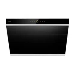
Model JQG9006/JQG9006-W
Produce size
L*D*H
35 7/8 × 18 7/16 × 17 7/16 "
(910 × 467 × 442 mm)
Net weight 70.1 lbs(31.8Kg)
Voltage/Frequency 120V/60Hz
Rated power input
of the range hood
210 W (light power included 3W × 2 )
Noise
Super-high-setting
56dB(A)
High-setting 53dB(A)
Medium-setting 48dB(A)
Low-setting 38.5dB(A)
SUPER-HIGH-SETTING;Press the HIGH-
SETTING/SUPER-HIGH-SETTING FAN
again and hold for 2s, the range hood can be
operated on the HIGH-SETTING and the
HIGH-SETTING/SUPER-HIGH-SETTING
indicator will fully illuminate; lightly press the
HIGH-SETTING/SUPER-HIGH-SETTING FAN
again, the motor will stop, and the HIGH-
SETTING/SUPER-HIGH-SETTING indicator
will return to low illumination.
(4) MEDIUM-SETTING FAN: Press the
MEDIUM-SETTING FAN lightly, the smoke
bafe plate will open automatically and the fan
will start up; while the MEDIUM-SETTING
indicator will fully illuminate, the range hood
is operated on medium-setting;press the
MEDIUM-SETTING FAN lightly again, the
motor will stop, and the MEDIUM-SETTING
indicator will return to low illumination.
(5) LOW-SETTING FAN: Press the button
lightly, the smoke baffle plate will open
automatically, the fan will start up, the LOW-
SETTING indicator will fully illuminate, and the
range hood will be operated on low-setting;
press the LOW-SETTING FAN lightly again,
the motor will stop, and the LOW-SETTING
indicator will return to low illumination.
(6) LIGHTING: The LIGHTING button opens
the smoke baffle plate and turns on the
lights. Once pressed, the button will fully
illuminate. Press the button again and the light
will turn off and the LIGHTING indicator will
return to low illumination.
(7) DELAY: Press the key lightly while the
range hood motor is working, the delay
indicator will fully illumination, and a two-minute
delay is activated; 2 minutes later, all functions
will turn off, the smoke baffle plate will be
closed automatically, and the range hood will
turn off.
During the delay, if you press the DELAY
button lightly once, the delay will be
stopped, the delay indicator will return to low
illumination, and the range hood will remain the
current working state.
Lightly press the any control panel button other
than the DELAY button once during the delay
to exit the delay, the DELAY indicator will
return to low illumination, and the function of
the pressed button operates.
When the range hood is not working, the
DELAY button is not working, and if the
button is pressed, an alarm sound will engage.
(8) LOCK SCREEN button: Once pressed and
held for 2 seconds when the range hood
fan is not operating, you will hear a “beep”
sound, the LOCK SCREEN button will
fully illuminate, all buttons will be locked, and
any pressing will be invalid; in order to unlock
the control panel, you must press and hold
the LOCK SCREEN button for another
2 seconds. When the range hood fan is in
operation, the LOCK SCREEN button is not
working, if the button is pressed, an alarm
sound will engage.
Hints:
1. The range hood will be turned off automatically
if it is not operated for 2 minutes in the standby
state;
2. It’s suggested that the range hood be turned
on during steaming to keep the kitchen air
fresh, otherwise, too much steam passing by
the Sensor Window may trigger the GESTURE
function.
Important Note:
• Reattach the grease filter after cleaning and
maintenance of the range hood. Do not
operate the appliance without the grease lter,
as it may cause safety hazards.
• The following diagrams are those of basic
models(JQG7505), for those derivative
models please refer to these diagrams of
basic models.
Caution:
Risk of demager due to corrosion.
• Always switch on the appliance while cooking
to avoid condensation. Condensate can
produce corrosion damage.
CLEANING AND MAINTENANCE
- 28 - - 29 -
range hood is operated on high-setting and
the lights will be turned on; wave hands
quickly through the sensor windows at two
sides again, all functions of range hood will
be turned off, the button indicator will be
turned off, the smoke baffle plate will be
closed automatically and the range hood is
off.When switching off, press Lighting and
Medium-setting Fan at the same time for 5
seconds to turn on/off the GESTURE function.
(2) POWER button: Once you press the
POWER button, the range hood will be
activated, the button will fully illuminate and the
other buttons on the control panel will display
low illumination. Lightly press the POWER
button again to turn off the range hood in the
working conditions. Once the range hood is
off, all functions are off, all buttons will cease
to illuminate, and the smoke bafe plate will be
closed automatically.
With the exception of the LOCK SCREEN
button, the other buttons will only work when
the POWER button is active.
(3) HIGH-SETTING/SUPER-HIGH-SETTING
FAN: Lightly press the button, the smoke bafe
plate will open automatically, and the fan will
start up, while the HIGH-SETTING/SUPER-
HIGH-SETTING indicator will fully illuminate
and the range hood will be operated on high-
setting; press the HIGH-SETTING/SUPER-
HIGH-SETTING FAN lightly again, the
motor will stop, and the HIGH-SETTING/
SUPER-HIGH-SETTING FAN indicator will
return to low illumination; press the HIGH-
SETTING/SUPER-HIGH-SETTING FAN and
hold for 2s, the HIGH-SETTING/SUPER-
HIGH-SETTING indicator will fully illuminate
in green, and the range hood is operated on
Operation
1. Fotile Range Hood Control Panel
(1)GESTURE function: Wave hands quickly
through the sensor windows at two sides, the
smoke bafe plate will automatically open, the
2. Operation Procedure
Power
Sensor
Window
Lock
Screen
Delay
Lighting
High-setting/
Super-high-
setting Fan
Medium-
setting
Fan
Low-
setting
Fan
Sensor
Window
Max static pressure 560 Pa
Caution:
1. dB noise in the above table complies with the IEC60704
standard, it is the sound pressure level, the corresponding
sound power level is: 68dB(A) for supper-high-setting,
65dB(A) for high-setting, 60dB(A) for medium-setting
and 52.5dB(A) for low-setting.
2. The noise --Sones -- in the above table is tested in accordance
with HVI-915-2015 in HVI-accredited laboratories in
American.
3. Such parameters as noise may have a deviation of less
than 10%.
HVI-2100 CERTIFIED RATINGS comply with
new testing technologies and procedures prescribed
by the Home Ventilating Institute, for off-the-shelf
products, as they are available to consumers.
Product
performance is rated at 0.1 in. static pressure, based
on tests conducted in a state-of-the-art test laboratory.
Sones are a measure of humanly-perceived loudness,
based on laboratory measurements.
Max static pressure 560 Pa
Caution:
1. dB noise in the above table complies with the IEC60704
standard, it is the sound pressure level, the corresponding
sound power level is: 68dB(A) for supper-high-setting,
66dB(A) for high-setting, 60dB(A) for medium-setting and
52.5dB(A) for low-setting.
2. Such parameters as noise may have a deviation of less
than 10%.
Model JQG9006/JQG9006-W
Produce size
L*D*H
35 7/8 × 18 7/16 × 17 7/16 "
(910 × 467 × 442 mm)
Net weight 70.1 lbs(31.8Kg)
Voltage/Frequency 120V/60Hz
Rated power input
of the range hood
210 W (light power included 3W × 2 )
Noise
Super-high-setting
56dB(A)
High-setting 53dB(A)
Medium-setting 48dB(A)
Low-setting 38.5dB(A)
SUPER-HIGH-SETTING;Press the HIGH-
SETTING/SUPER-HIGH-SETTING FAN
again and hold for 2s, the range hood can be
operated on the HIGH-SETTING and the
HIGH-SETTING/SUPER-HIGH-SETTING
indicator will fully illuminate; lightly press the
HIGH-SETTING/SUPER-HIGH-SETTING FAN
again, the motor will stop, and the HIGH-
SETTING/SUPER-HIGH-SETTING indicator
will return to low illumination.
(4) MEDIUM-SETTING FAN: Press the
MEDIUM-SETTING FAN lightly, the smoke
bafe plate will open automatically and the fan
will start up; while the MEDIUM-SETTING
indicator will fully illuminate, the range hood
is operated on medium-setting;press the
MEDIUM-SETTING FAN lightly again, the
motor will stop, and the MEDIUM-SETTING
indicator will return to low illumination.
(5) LOW-SETTING FAN: Press the button
lightly, the smoke baffle plate will open
automatically, the fan will start up, the LOW-
SETTING indicator will fully illuminate, and the
range hood will be operated on low-setting;
press the LOW-SETTING FAN lightly again,
the motor will stop, and the LOW-SETTING
indicator will return to low illumination.
(6) LIGHTING: The LIGHTING button opens
the smoke baffle plate and turns on the
lights. Once pressed, the button will fully
illuminate. Press the button again and the light
will turn off and the LIGHTING indicator will
return to low illumination.
(7) DELAY: Press the key lightly while the
range hood motor is working, the delay
indicator will fully illumination, and a two-minute
delay is activated; 2 minutes later, all functions
will turn off, the smoke baffle plate will be
closed automatically, and the range hood will
turn off.
During the delay, if you press the DELAY
button lightly once, the delay will be
stopped, the delay indicator will return to low
illumination, and the range hood will remain the
current working state.
Lightly press the any control panel button other
than the DELAY button once during the delay
to exit the delay, the DELAY indicator will
return to low illumination, and the function of
the pressed button operates.
When the range hood is not working, the
DELAY button is not working, and if the
button is pressed, an alarm sound will engage.
(8) LOCK SCREEN button: Once pressed and
held for 2 seconds when the range hood
fan is not operating, you will hear a “beep”
sound, the LOCK SCREEN button will
fully illuminate, all buttons will be locked, and
any pressing will be invalid; in order to unlock
the control panel, you must press and hold
the LOCK SCREEN button for another
2 seconds. When the range hood fan is in
operation, the LOCK SCREEN button is not
working, if the button is pressed, an alarm
sound will engage.
Hints:
1. The range hood will be turned off automatically
if it is not operated for 2 minutes in the standby
state;
2. It’s suggested that the range hood be turned
on during steaming to keep the kitchen air
fresh, otherwise, too much steam passing by
the Sensor Window may trigger the GESTURE
function.
Important Note:
• Reattach the grease filter after cleaning and
maintenance of the range hood. Do not
operate the appliance without the grease lter,
as it may cause safety hazards.
• The following diagrams are those of basic
models(JQG7505), for those derivative
models please refer to these diagrams of
basic models.
Caution:
Risk of demager due to corrosion.
• Always switch on the appliance while cooking
to avoid condensation. Condensate can
produce corrosion damage.
CLEANING AND MAINTENANCE

- 30 - - 31 -
• Surface damage due to incorrect cleaning.
Clean stainless steel surfaces in the direction
of the grain only. Do not use any stainless
steel cleaners for operator controls.
• Surface damage due to strong or abrasive
cleaning agents.
• Replace faulty LED lights to prevent the
remaining lights form overloading.
Warning:
• The range hood should only be cleaned as
instructed; otherwise, it may ignite.
• Please remember not to wet the motor and/or
the control panel, as it may result in damaging
the electric circuits or potential hazards.
• Do not clean the appliance with chemical
agents, such as gasoline, acids, benzene and
solvents.
Risk of Electric Shock:
• Penetrating moisture may result in an electric
shock. Prior to cleaning and maintenance,
pull out the mains plug or switch off the circuit
breaker in the fuse box.
• Do not use any high-pressure cleaners or
steam cleaners, which can result in an electric
shock.
Risk of Fire:
• Grease deposits in the grease filter and
Grease Cup may catch re.
•
Please do not place ammable materials in the
oil cup, such as plastic wrap, paper towels, etc.
• Please avoid excessive accumulation of
oil and regularly clean oil cup and other
components which can accumulate oil.
Risk of Injury:
• Unplug the appliance from the mains or switch
off the circuit breaker in the fuse box before
installation, cleaning, maintenance and repair
in order to avoid electric shock.
• The range hood may have sharp edges. Be
careful to avoid cuts and abrasions during
installation and cleaning. Do wear qualified
protective gloves.
• While the range hood is in operation, do not
insert your hand into the area housing the fan.
• The appliance will become hot during
operation, especially near LED lights. Allow
the appliance to cool down before cleaning.
Do not touch lamps during or soon after
operation. Burns may occur.
• If you would like to schedule a deep cleaning
for your appliance, please contact our
authorized service center.
• Fotile suggests that you clean the surface of
the appliance for better use.
1) Neutral detergent may be used to clean
stains on the range hood. However, avoid
touching the control panel. Wipe some
detergent on the stains and let the detergent
sit. Do not let the detergent sit for an extended
period of time, as it can cause damages to the
appliance’s surface. Then, wipe off the stain
with a soft cloth and the left detergent with a
slightly wet cloth. Next, use another cloth to
dry the appliance.
2) Stains on the range hood should be cleaned
within a short time period, as to prevent the
stains from becoming permanent.
3) Abrasive detergents, such as a salt solution,
disinfectant or bleach powder cannot be used
to clean the appliance. Wipe off the detergent
with a wet, soft cloth. Next, use another cloth
to dry the appliance.
Warning:
Do not clean the appliance with
abrasive tools, such as steel wool, brushes,
and coarse cloths, as these materials will
permanently scratch the surface of the hood.
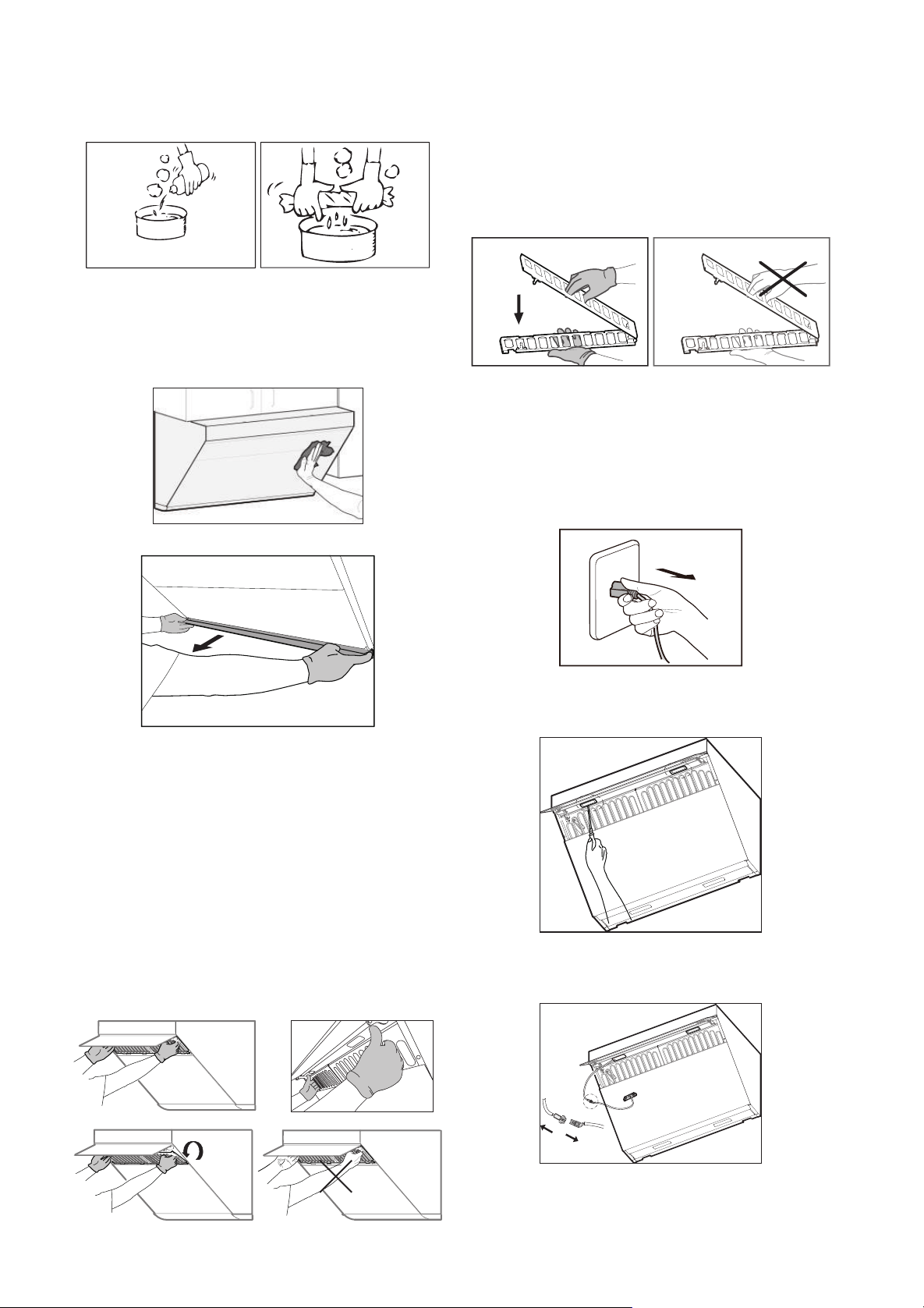
Preparations before Cleaning:
1.Unplug the range hood or turn off the power
socket.
2. Clear the cookware on the burners.
3. Prepare a neutral detergent and a soft cloth
(or soft brush) for stain removal and cleaning.
Washing and cleaning the surface, Grease
Cup, and grease lter: (The cleaning can be
done by the user)
1.Clean the surface of the range hood.
2. Take out the oil cup horizontally and wash it.
Warning:
For the safety of you and your family,
please regularly clean out the oil in the oil cup and
sediment on the external surface of the oil cup
to avoid fire risk. Please operate with protective
gloves.
3.Lightly press the POWER button. Then,
lightly press the LIGHTING button. After the
LIGHTING button is pressed, the smoke bafe
plate will open.
4. Hold the two sides of the grease filter and
pull sideward to unlock it.
★
Suggestion:
In order to protect the health of
you and your family, the lter should be cleaned
regularly and it is dishwasher safe for your
convenience.
Warning:
Please wear the qualified protective
gloves in operation.
Replacing LED Lights:
1.Lightly press the POWER button; then, press
the LIGHTING button. After the LIGHTING button
is pressed, the smoke bafe plate will open.
2. Unplug the range hood or turn off the power
socket.
3. Use a small flat-head screwdriver to gently
pry the LED assembly out.
4. Disconnect the wires and then replace the
LED lights.
Use type lamp is self-ballasted fluorescent
reector lamp - Integral induction type ballast.
- 30 - - 31 -
• Surface damage due to incorrect cleaning.
Clean stainless steel surfaces in the direction
of the grain only. Do not use any stainless
steel cleaners for operator controls.
• Surface damage due to strong or abrasive
cleaning agents.
• Replace faulty LED lights to prevent the
remaining lights form overloading.
Warning:
• The range hood should only be cleaned as
instructed; otherwise, it may ignite.
• Please remember not to wet the motor and/or
the control panel, as it may result in damaging
the electric circuits or potential hazards.
• Do not clean the appliance with chemical
agents, such as gasoline, acids, benzene and
solvents.
Risk of Electric Shock:
• Penetrating moisture may result in an electric
shock. Prior to cleaning and maintenance,
pull out the mains plug or switch off the circuit
breaker in the fuse box.
• Do not use any high-pressure cleaners or
steam cleaners, which can result in an electric
shock.
Risk of Fire:
• Grease deposits in the grease filter and
Grease Cup may catch re.
•
Please do not place ammable materials in the
oil cup, such as plastic wrap, paper towels, etc.
• Please avoid excessive accumulation of
oil and regularly clean oil cup and other
components which can accumulate oil.
Risk of Injury:
• Unplug the appliance from the mains or switch
off the circuit breaker in the fuse box before
installation, cleaning, maintenance and repair
in order to avoid electric shock.
• The range hood may have sharp edges. Be
careful to avoid cuts and abrasions during
installation and cleaning. Do wear qualified
protective gloves.
• While the range hood is in operation, do not
insert your hand into the area housing the fan.
• The appliance will become hot during
operation, especially near LED lights. Allow
the appliance to cool down before cleaning.
Do not touch lamps during or soon after
operation. Burns may occur.
• If you would like to schedule a deep cleaning
for your appliance, please contact our
authorized service center.
• Fotile suggests that you clean the surface of
the appliance for better use.
1) Neutral detergent may be used to clean
stains on the range hood. However, avoid
touching the control panel. Wipe some
detergent on the stains and let the detergent
sit. Do not let the detergent sit for an extended
period of time, as it can cause damages to the
appliance’s surface. Then, wipe off the stain
with a soft cloth and the left detergent with a
slightly wet cloth. Next, use another cloth to
dry the appliance.
2) Stains on the range hood should be cleaned
within a short time period, as to prevent the
stains from becoming permanent.
3) Abrasive detergents, such as a salt solution,
disinfectant or bleach powder cannot be used
to clean the appliance. Wipe off the detergent
with a wet, soft cloth. Next, use another cloth
to dry the appliance.
Warning:
Do not clean the appliance with
abrasive tools, such as steel wool, brushes,
and coarse cloths, as these materials will
permanently scratch the surface of the hood.
Preparations before Cleaning:
1.Unplug the range hood or turn off the power
socket.
2. Clear the cookware on the burners.
3. Prepare a neutral detergent and a soft cloth
(or soft brush) for stain removal and cleaning.
Washing and cleaning the surface, Grease
Cup, and grease lter: (The cleaning can be
done by the user)
1.Clean the surface of the range hood.
2. Take out the oil cup horizontally and wash it.
Warning:
For the safety of you and your family,
please regularly clean out the oil in the oil cup and
sediment on the external surface of the oil cup
to avoid fire risk. Please operate with protective
gloves.
3.Lightly press the POWER button. Then,
lightly press the LIGHTING button. After the
LIGHTING button is pressed, the smoke bafe
plate will open.
4. Hold the two sides of the grease filter and
pull sideward to unlock it.
★
Suggestion:
In order to protect the health of
you and your family, the lter should be cleaned
regularly and it is dishwasher safe for your
convenience.
Warning:
Please wear the qualified protective
gloves in operation.
Replacing LED Lights:
1.Lightly press the POWER button; then, press
the LIGHTING button. After the LIGHTING button
is pressed, the smoke bafe plate will open.
2. Unplug the range hood or turn off the power
socket.
3. Use a small flat-head screwdriver to gently
pry the LED assembly out.
4. Disconnect the wires and then replace the
LED lights.
Use type lamp is self-ballasted fluorescent
reector lamp - Integral induction type ballast.

- 32 - - 33 -
FAQ
Warning:
Risk of Electric Shock
• Incorrect repairs are dangerous. Repairs
may only be carried out and damaged power
cables replaced by our authorized service
center, or certied electricians.
•
If there is a defect in the product, please
disconnect the power plug or shut off the power
supply of the range-hood socket in order to
avoid electric shock. Please contact the service
center authorized by FOTILE.
• To avoid electric shock, please disconnect the
power plug or shut off the power supply of the
range-hood socket before replacing the LED
light.
• If an abnormal condition occurs during
use, immediately stop using the product and
disconnect the power plug or shut off the power
supply of the range-hood socket in order to
check the following:
Problem/Issue Possible Cause
After the POWER button
is pressed, the range hood
remains off and the button
does not illuminate.
The appliance may
be unplugged
The motor works, but the
control panel buttons do
not illuminate.
LED lights have
been damaged
If the problem/issue with the appliance still
persists after ruling out the possible cause(s),
please contact our authorized service center for
assistance.
SERVICE INFORMATION
Warning
• In the event of an abnormal condition during
the use of the range hood, please stop using it,
disconnect the power plug or shut off the power
supply of the range-hood socket. Please contact
the service center authorized by FOTILE.
• The appliance must only be repaired by
professionally trained and certified technician;
otherwise, severe injuries may occur.The ventilator
shall be not allowed to be repaired by any
party other than Fotile’s appointed technicians.
Otherwise it may cause serious consequences
and exempt the product from warranty.
• Please do not repair or replace any part of the
Range Hood unless it is specically suggested
in the manual. All other maintenance work
should be carried out by qualied technicians.
• The following circumstances do not fall into
the scope of free warranty, and a fee will be
charged for repair.
1) Damage resulting from improper handling,
installation, use, maintenance and
safekeeping conducted by customer.
2) Failure and damage caused by using
the product beyond the normal operating
conditions (damage caused in the case that
the voltage is higher than 132V or lower than
104V).
3) The product installed, dismantled or repaired
by customer or any party other than Fotile’s
appointed service staff or agency.
4) Discrepancy between the information on the
purchase voucher and the warranty card and
the product.
5) Product damage caused by force majeure
(such as natural disaster and war, etc.).
6) Product failure or damage arising from use
not in conformity with the “instructions”.
INSTALLATION
6.1 Installation Instructions
Important Note:
-Max wattage: 3W
-Voltage range: 8.5~12V
-Dimensions: width 2 13/16
"
(70 mm)/depth
7/8
"
(21 mm)/height 3/4
"
(19mm)
Risk of Electric Shock:
To avoid electric shock, please disconnect the
power plug or shut off the power supply of the
range-hood socket before replacing the LED light.
installation, please turn off the main gas valve rst.
3. Do not connect the range hood duct to a duct
used to exhaust hot air or fumes from another
appliance.
4. Two installers are recommended due to
the large size and heavy weight of the range
hood. Since the installation is complex and
the appliance is heavy, professional installers
are required to install the appliance as
outlined in this manual.
5. After the appliance fixed, the plug should
be accessible.
6. Make sure to keep the appliance
horizontally.
7. Ensure that the appliance functions
normally after the installation is complete.
Warning:
• In order to reduce the risk of fire, electric
shock, or injury to persons, please carefully
read the following:
1. The installation and wiring of the appliance
should only be carried out by a professional
electrician in accordance with current national
or local electric safety regulations, including
fire-rated construction. Non-professional
personnel should not conduct installation.
Proper installation is the responsibility of the
installer.
Product failure due to improper installation is
not covered under the Fotile warranty.
2. Please use standard installation equipment
and tools provided by Fotile to ensure safe
installation. Make sure to use the expansion
tube and expansion bolt provided by our
company, in case the range hood falls
down accidentally. The hole drilled into the
wall should precisely match the size of the
expansion tube, otherwise the range hood will
not be properly secured to the wall and may
fall down.
3. The range hood should be connected to a
standard power socket with safe grounding.
The midway connection, prolonged electric
line or multi-socket wiring may cause electric
shock, overheating and even re.
Power off before wiring and make sure
proper measures have been taken to avoid
unexpected connection.
• Prior to installation, please read the Fotile
Range Hood Installation carefully and save it
for the local inspector’s future reference.
• This appliance must be installed in accordance
with National Electrical Codes, as well as all
state, municipal and local codes.
• The appliance must be equipped with safe circuit
breaker and installed with safe grounding.
• The correct voltage, frequency and amperage
must be supplied to the appliance according to
the proper voltage, frequency and amperage
ratings listed on the product rating plate.
• This installation must be completed by Fotile
authorized service center, or certied installers.
• Please record the model and serial number
before installing the range hood. Position
of plaque can be referred to in figure A as
follows.
• The following diagrams are those of basic
models(JQG7505), for those derivative
models please refer to these diagrams of
basic models:
Caution:
• Please carefully read all instructions prior to
installation. Please give special consideration
to the following items:
1.If you are renovating your kitchen, be careful
to not expose the exterior of the range hood.
Building materials, dust, paint, coating, and
gases will corrode and tarnish the surface of
the range hood. It is recommended that you
install the range hood after all renovations are
completed.
2. If you need to remove your gas burner before
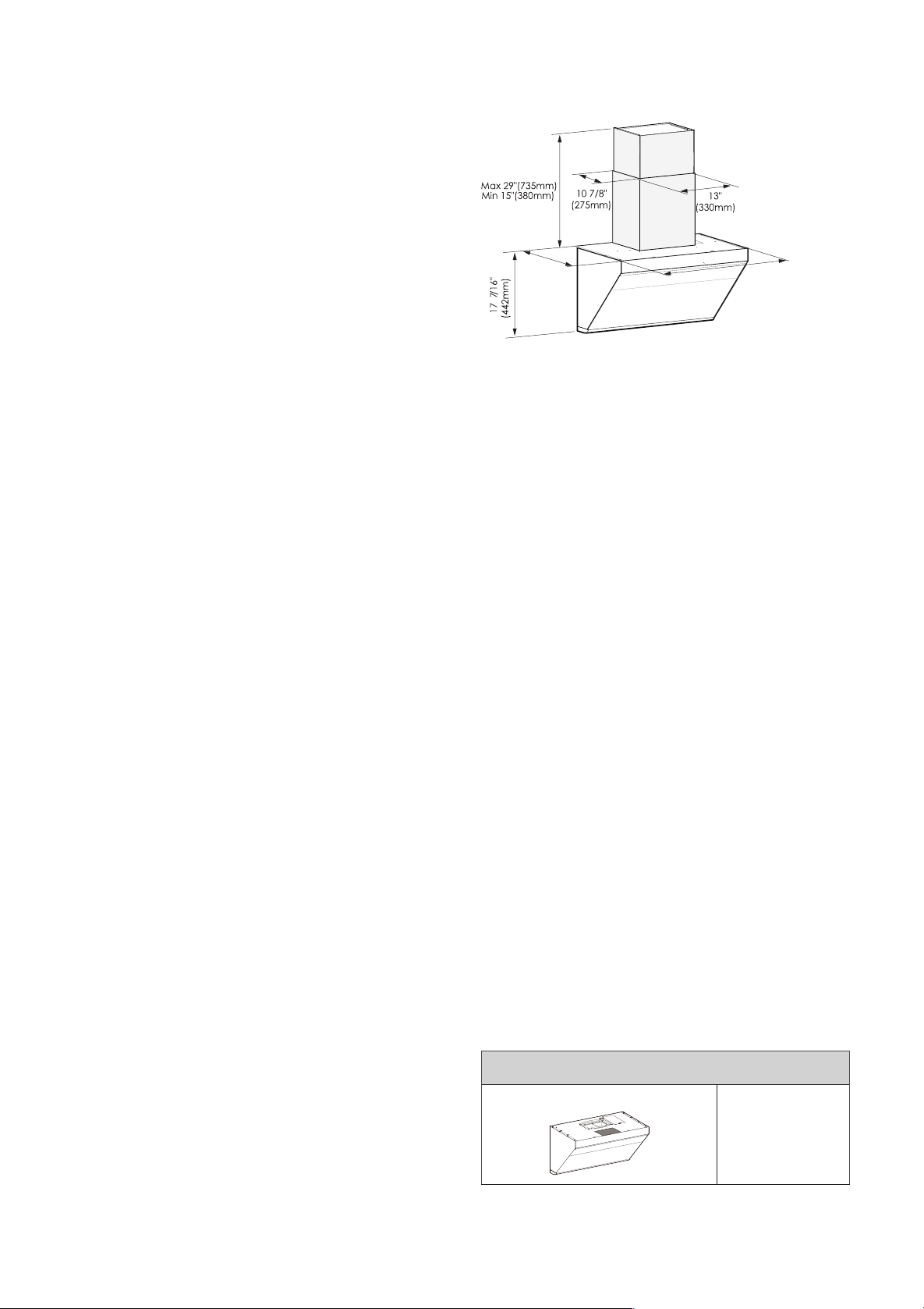
- 34 - - 35 -
4. During installation, switch off the circuit
breaker in the fuse box during installation.
If the supply cord is damaged, it must be
replaced by a special cord or assembly
available from the manufacturer or its service
agent.
5. The appliance should only be installed,
removed and maintained by qualified
technicians to prevent risks like electric
shocks, falling or res from occurring.
Risk of Injury:
• Unplug the appliance from the mains or switch
off the circuit breaker in the fuse box before
installation, cleaning, maintenance and repair
in order to avoid electric shock.
• The range hood may have sharp edges. Be
careful to avoid cuts and abrasions during
installation and cleaning. Do wear qualified
protective gloves.
Warning Before Installation
• Prior to installation, ensure that the exhaust
outlet is free of debris, as they may damage
the range hood.
• A straight and short ducting run will ensure a
high performance of the range hood.
• A curving and long ducting run should be
avoided, as it will lower the performance of
the range hood.
• Strictly seal the connection between the duct
and duct hole with duct tape. Ensure that the
connection between the duct and the duct cover
is secure, and seal it with aluminum tape.
• A small duct hole will lower the performance
of the range hood. Therefore, it is highly
recommended that you cut a duct hole equal
to or larger than 6"(152.4mm) of the size.
• The bolts used in this product are metric-size
bolts, please do not apply any unqualified
bolts.
6.2 Product Dimensions
187/16"
(467mm)
297/8"(758mm)
(JQG7505/JQG7505-W)
357/8"(910mm)
(JQG9006/JQG9006-W)
Wall Preparation
The wall should be strong enough to support the
range hood. As for hollow wall or hollow plate, The
minimum thickness of the lumber should be 13/16"
(30mm). As for concrete wall, the installation can be
directly operated. The range hood should be rmly
xed on the wall.
Ductwork Installation
Risk of Injury:
• Unplug the appliance from the mains or switch
off the circuit breaker in the fuse box before
installation, cleaning, maintenance and repair
in order to avoid electric shock.
• The range hood may have sharp edges. Be
careful to avoid cuts and abrasions during
installation and cleaning. Do wear qualified
protective gloves.
• When cutting or drilling into walls or ceilings,
do not damage electrical wiring and other
hidden utilities.
• Ducted fans must always be vented to the
outdoors.
• To reduce the risk of fire and to properly
exhaust air, always duct air outside. Do not
vent exhaust air into spaces within walls,
ceilings, into attics, crawl spaces or garages.
6.3 List of Accessories:
Packing List
Standard Conguration
Product
1
Duct Cover
1
Gasket
1
Grease Cup
(JQG7505/JQG7505-W)
1
Grease Cup
(
JQG9006/JQG9006-W
)
2
Product Manual
1
Installation Paper Template
1
Warranty Card
1
Duct Bracket
1
Hook Screw
#8×1 7/16"(ST4.2×36mm)
4
Expansion Tubes for Tiles
φ1/4"×1 5/16"(φ5.3×32mm)
4
Expansion Tubes for Plasterboards
φ3/16"×1 5/8"(φ4×40mm)
4
Duct Cover Screws
#8×3/4"(M4×18mm)
4
Upper Plate Fastening Screws
#10×2 13/16"(M5×70mm)
4
(One of them is
for standby)
Set Screw Gasket for Upper
Cabinet Boards
φ1 5/16"(φ32mm)
4
(1 for standby)
Housing Assembly Accessories (optional)
Blower Housing
1
Decorative Cover
1
Decorative Cover Bracket
1
Safety Buffer Bafe
1
Duct Cover Screws
#8×7/16"(M4×10mm)
4
Hook Screw
#8×1 7/16"(ST4.2×36mm)
3
Expansion Tubes for Tiles
φ1/4"×1 5/16"(φ5.3×32mm)
3
Expansion Tubes for Plasterboards
φ3/16"×1 5/8"(φ4×40mm)
3
Screws
#4×3/4"(ST2.9×19mm)
3
Decorative Plate Assembly Accessories (with upper
cabinet)
6"(152.4mm) or 4"(101.6mm)
Decorative Plate
1
Fixed Decorative Plate Screws
#6×1 7/16"(ST3.5×35mm)
4
The following accessories must be purchased
separately (please contact the authorized
Fotile
branch
Wood Screws
#10×2 9/16"(ST5×65mm)
4
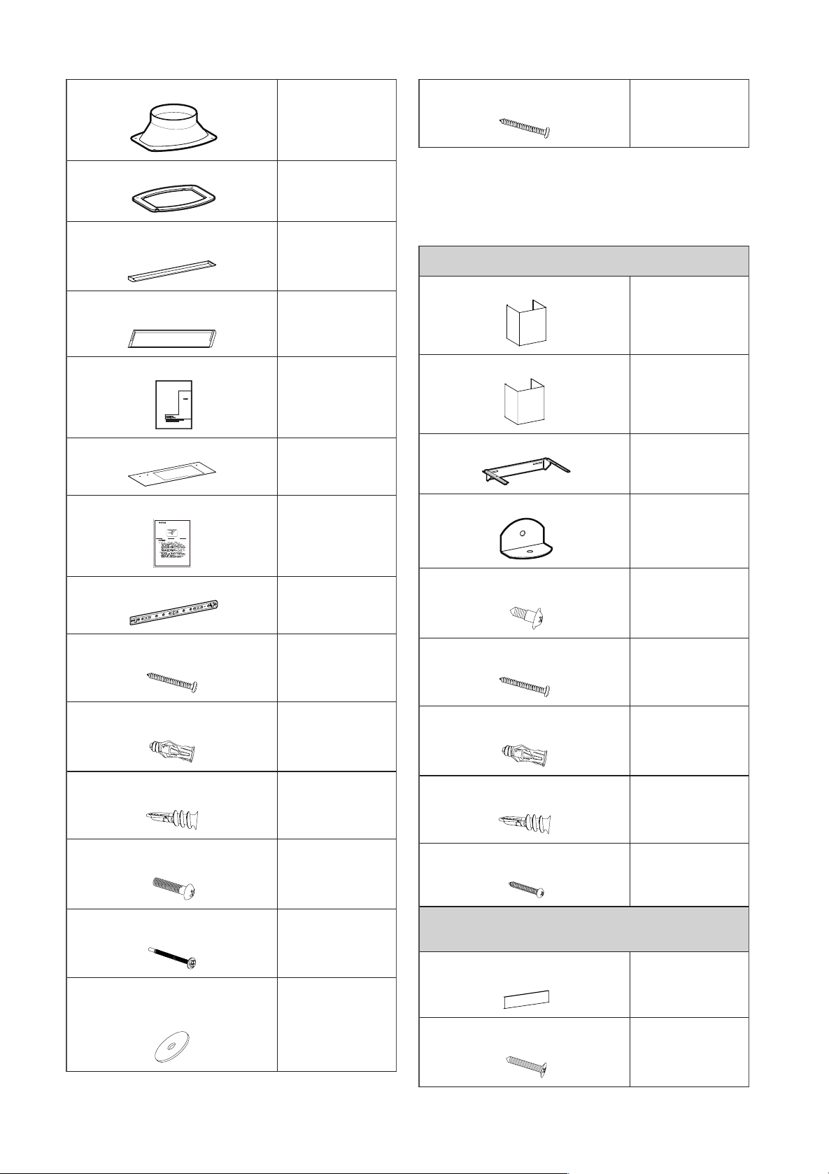
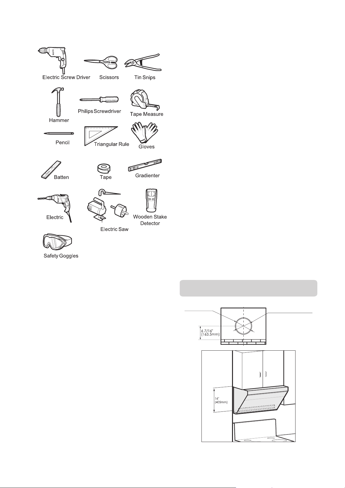
- 36 - - 37 -
6.4 Installation Tools:
6.5 Installation Procedure:
In order to secure the safe use of the range
hood and maximize its ability to ventilate cooking
fumes, the installation height is suggested as
follows: The distance from the countertop of the
gas stove to the top board of the range hood
shall not be less than 29 9/16"(750mm) and
shall not be more than 32 1/2"(825mm). This
installation height is only applicable to electric
ranges. If the range hood is installed above a
gas range, the minimum distance between the
supporting surface of the cooking appliance
on the range and the lowest part of the range
hood should be at least 24”(610mm)(in USA)/25
5/8”(650mm)(in Canada). If the installation
instructions for the gas range specify a larger
installation distance, this should be considered.
The installation height of the range hood is the
recommended value, and the cupboard and the
range hood shown in the gure is for reference
only. When the installation height of this product
(i.e. the distance between the supporting
surface of the cooking appliance on the range
and the lowest part of the range hood) is lower
than 24”(610mm)(in USA)/25 5/8”(650mm)
(in Canada), all parts below 24”(610mm)(in
USA)/25 5/8”(650mm)(in Canada) are non-
flammable parts of the range hood or parts
working under safe and ultra-low voltage, and
the deformation of these parts will not affect the
protection against the touch of live parts.
Where there are relevant laws stipulating the
mounting height of range hood in the state
or region, the laws shall prevail ( Included
but not limited to architecture and firefighting
regulations and standards). However, the effect
of cooking fumes ventilation might be affected.
The range hood can be installed in three ways,
either with or without the upper cabinet.
Caution:
1. One of the wood screws(#10×2 9/16"(ST5×65mm))
for duct bracket must be fastened to the wooden beam.
2. If it is necessary to drill the duct outlet at the back
wall, the distance from the top plane of the range
hood to the center of the hole should be at least 8"
(203mm).
Warning:
Excessively low installation height can
cause overheating of the glass panel, increasing the
possibility of breaking.
Installation of the Fotile Range Hood with
an Upper Cabinet:
Diameter of smoke
tube Φ6" (152.5mm)
Diameter of hole digging
Φ
6 1/2" (165mm)
Warning:
Do wear qualied protective gloves.
1. Unpack the appliance and check the List of
Accessories.
2. Locate the wooden beam and mark the location
with a pencil.
Framing Stud
3. Locate the duct bracket. Determine the
central point and mark the centerline on the
wall where the hood will be installed. Also, mark
the point where the central line and the lowest
point on the bottom board of the top cabinet
meet. This is the location, in which to secure
the bracket. Mark screw hole locations on the
wall. The distance between the lowest point on
bottom board of the top cabinet and the center
of the bracket should be 16" (405mm).
Caution:
One of the wood screws(#10×2
9/16"(ST5×65mm)) for main engine must be
fastened to the beam.Screws must be fixed
at Hole A and B in the drawing; also wood
screws(#10×2 9/16"(ST5×65mm)) must be xed
at bracket bores with corresponding wooden
stakes in Area C.
4.Fixing hooks:
1) Punch marks are on tiles (marble): Punch holes
(φ3/8"(φ8mm)) with an electric drill at the marks,
and embed expansion tube for tiles(φ1/4"×1
5/16"(φ5.3×32mm)); fix hook with hook
screws(#8×1 7/16"(ST4.2×36mm)), and keep the
hook level with a level ruler.
2) Punch marks are on plasterboards: Screw
the expansion tube for plasterboards(φ3/16"×1
5/8"(φ4×40mm)) into walls with screwdrivers
at the marks; fix hooks with hook screws(#8×1
7/16"(ST4.2×36mm)), and keep the hook
horizontal with a level ruler.
5 .Place the hole-drilling template with the side
of the hole-drilling dimension drawing facing
down on the bottom of the upper cabinet, and
then drill the holes as indicated on the hole-
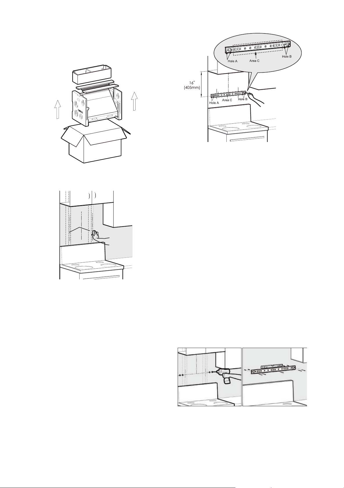
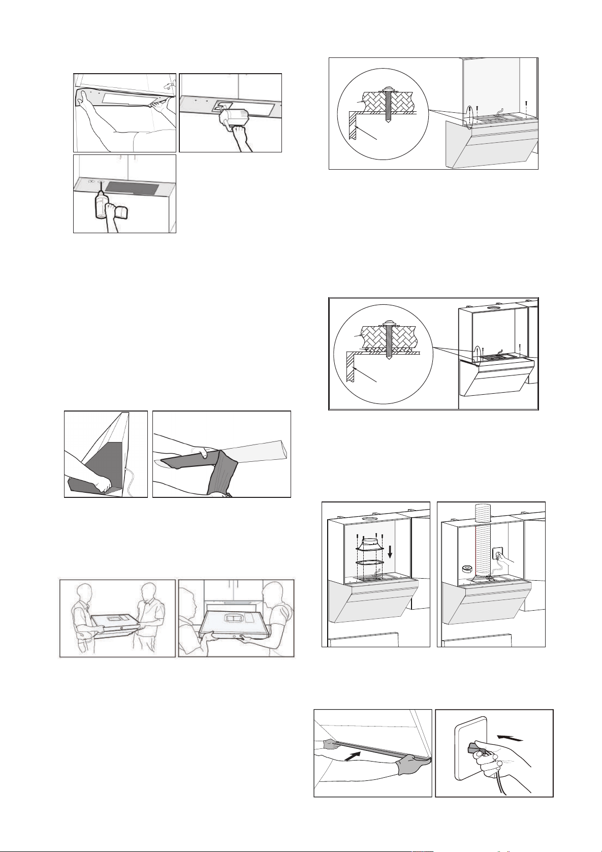
- 38 - - 39 -
Installation Instructions for the Decorative
Plate with Upper Cabinet :
Caution:
Please confirm the height of the top
cabinet. If the upper cabinet is over 32 1/2" es
(825mm) high, 6"(152.4mm) or 4"(101.6mm)
decorative plate is preferred.
Diameter of smoke
tube
Φ6" (152.5mm)
Diameter of hole digging
Φ
6 1/2" (165mm)
7 11/16"(194.4mm)
or
5 11/16"(143.6mm)
6"(152.4mm)
or
4"(101.6mm)
1.Unpack the appliance and check the List of
Accessories.
drilling template.
Caution:
Wear safety goggles when drilling.
In case of batten at the wall facing the bottom
plate, the rear wall side of the paper template shall
be cut as per the thickness of the batten.
If it is necessary to x the hook on the tile, the “Rear
Wall” side of the hole-drilling template should be
attached to the bottom of the upper cabinet, using
the tile surface as a reference.
6. Remove the protective film of the stainless
steel surface and Grease Cup at both sides of
the range hood.
7. Lift and position the hood onto the brackets
at the bottom of the backside while keeping an
angle between the wall and the hood, and then
push the hood against the wall tightly.
Caution:
Two installers are required to ensure
safe installation.
8.Use three sets of screws (#10×2
13/16"(M5×70mm)) for upper cabinet boards
and supporting gaskets (φ1 5/16"(φ32mm))
to fix the main body, and secure at least two
screws before releasing.
the bottom
board of the
top cabinet
Range hood shel
If there is a big gap between the bottom board
of the top cabinet and the top of the range hood,
please add wood pads based on the gap size near
the three #10×2 13/16"(M5×70mm) screws to
avoid range hood shell deformation caused by the
tightening of screws, which will affect the use of
the range hood.
Range hood shel
the bottom
board of the
top cabinet
Wooden plate
9. Place the seal (notch downward) at the air
outlet of the machine and fix the outlet housing
with 4 outlet-housing bolts of #8×3/4"(M4×18mm).
Then, secure the duct to the duct cover and seal
the connection with aluminum tape.
10. Make sure the hood is leveled. Install the
Grease Cup, and plug in the appliance for a test
run.
Warning:
Please wear the qualified protective
gloves in operation.
Caution:
Please run the machine and test if
the smoke pipe leaks air after it is sealed with
aluminum foil tape. The smoke pipe should be
able to be straightened as much as possible.
2. Locate the wooden beam and mark the
location with a pencil.
Framing Stud
3. Locate the duct bracket. Determine the
central point and mark the centerline on the
wall where the hood will be installed. Also, mark
the point where the central line and the top
cabinet meet. This is the location, in which to
secure the bracket. Mark screw hole locations
on the wall. The upper edge (the xed surface
between the decorative sheet and the board
of the top cabinet) of the bottom board of the
top cabinet shall be deemed as the location
datum. And the distance between the upper
edge and the center of the bracket shall be 7
11/16"(194.4mm)for 6"(152.4mm) decorative
sheet and 5 11/16"(143.6mm) for 4"(101.6mm)
decorative sheet.
The upper edge (the fixed
surface between the decorative
sheet and the board of the top
cabinet) of the bottom board of
the top cabinet shall be deemed
as the location datum.
5 11/16"
(143.6mm)
or
7 11/16"
(194.4mm)
Caution:
One of the wood screws(#10×2
9/16"(ST5×65mm)) for main engine must be
fastened to the beam.Screws must be fixed
at Hole A and B in the drawing; also wood
screws(#10×2 9/16"(ST5×65mm)) must be xed
at bracket bores with corresponding wooden
stakes in Area C.
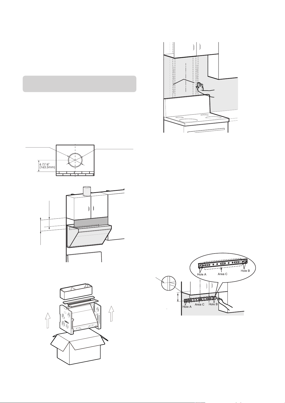
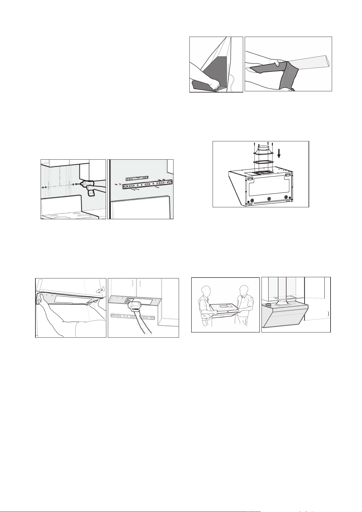
- 40 - - 41 -
4.Fixing hooks:
1) Punch marks are on tiles (marble): Punch
holes (φ3/8"(φ8mm)) with an electric drill at
the marks, and embed expansion tube for
tiles(φ1/4"×1 5/16"(φ5.3×32mm)); x hook with
hook screws(#8×1 7/16"(ST4.2×36mm)), and
keep the hook level with a level ruler.
2) Punch marks are on plasterboards: Screw
the expansion tube for plasterboards(φ3/16"×1
5/8"(φ4×40mm)) into walls with screwdrivers
at the marks; x hooks with hook screws(#8×1
7/16"(ST4.2×36mm)), and keep the hook
horizontal with a level ruler.
5.
Place the hole-drilling template with the side
of the hole-drilling dimension drawing facing
down on the bottom of the upper cabinet, and
then drill the holes as indicated on the hole-
drilling template.
Caution:
Wear safety goggles when drilling.
In case of batten at the wall facing the bottom
plate, the rear wall side of the paper template
shall be cut as per the thickness of the batten.
If it is necessary to x the hook on the tile, the
“Rear Wall” side of the hole-drilling template
should be attached to the bottom of the upper
cabinet, using the tile surface as a reference.
6. Remove the protective film of the stainless
steel surface and Grease Cup at both sides of
the range hood.
7. Place the seal (notch downward) at the
air outlet of the machine and fix the outlet
housing with 4 outlet-housing bolts of
#8×3/4"(M4×18mm).
8. Lift and position the hood onto the brackets at
the top of the backside while keeping an angle
between the wall and the hood, and then push
the hood against the wall tightly. Secure the
duct to the duct cover and seal the connection
with aluminum tape.
Caution:
Two installers are required to ensure
safe installation.
9. Install the decorative plate.
Fix the decorative panel in place with 4 #6 × 1
7/16" (ST3.5×35mm) wood screws and fix the
decorative panel on the upper cabinet plate (the
wood screws are provided in the accessory bag
in the packing box of the decorative panel).
10. Make sure the hood is leveled. Install the
Grease Cup, and plug the appliance for a test run.
Warning:
Please wear the qualified protective
gloves in operation.
Caution:
Please run the machine and test if
the smoke pipe leaks air after it is sealed with
aluminum foil tape. The smoke pipe should be
able to be straightened as much as possible.
Installation Instructions for the Decorative
Cover Without Upper Cabinet
Diameter of smoke
tube Φ6" (152.5mm)
Diameter of hole digging
Φ
6 1/2" (165mm)
1. Unpack the appliance and check the List of
Accessories.
2. Locate the wooden beam and mark the
location with a pencil.
Framing Stud
3. Locate the duct bracket, safety buffer bafe
and decorative cover bracket:
safety stop
mounting hole
2
5
/1
6
"(
5
8
.5
m
m
)
4
9
/1
6
"(
11
5
.5
m
m
)
Max 29 15/16"(760mm)
Max 30 7/8"(783mm)
Min 27 7/8"(708mm)
4
9/16"(115.5mm)
Hole A
Area C
Hole B
Hole A
Area C
Hole B
Caution:
one of the wood screws(#10×2
9/16"(ST5×65mm)) for main engine must be
fastened to the beam.Screws must be fixed
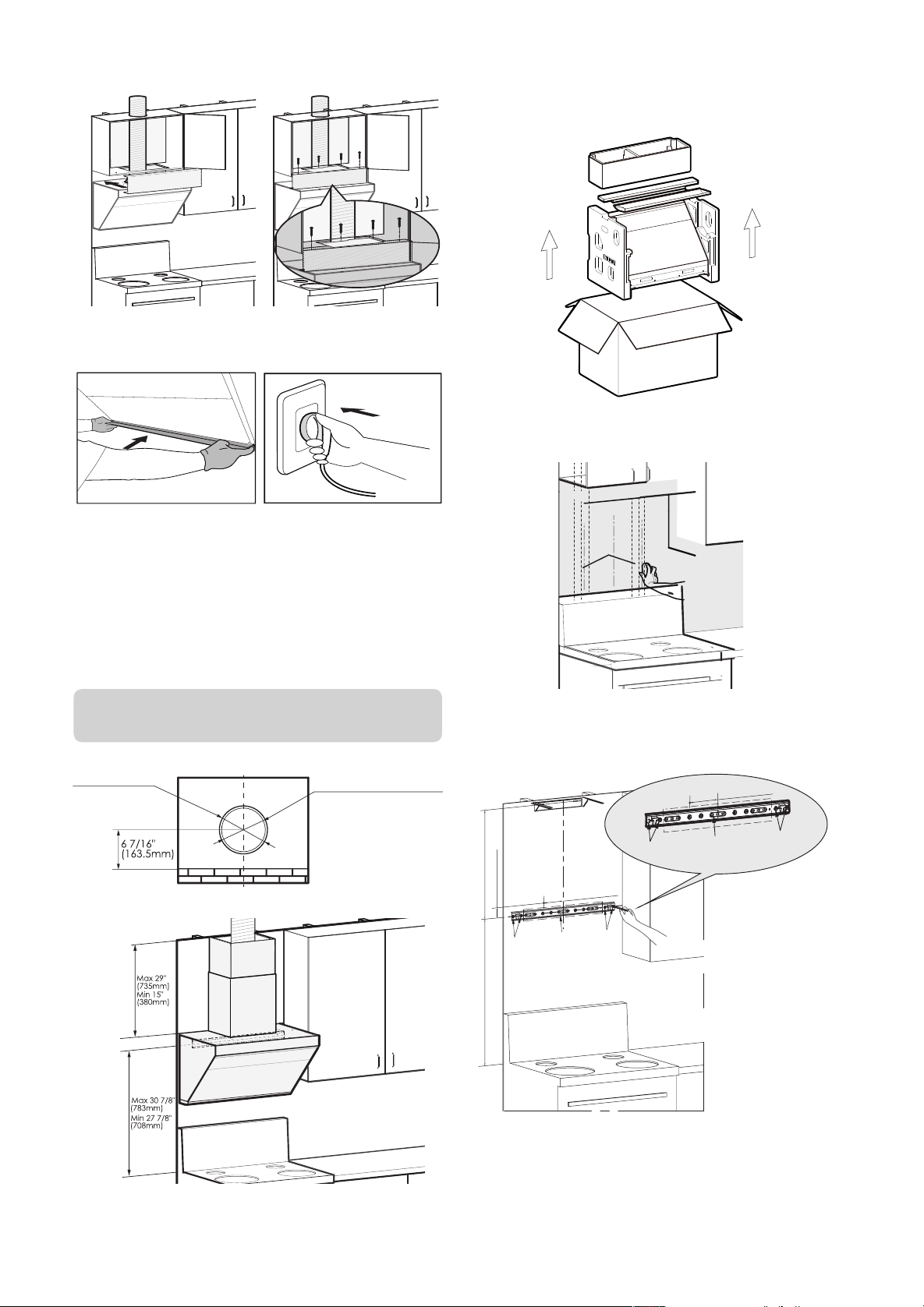
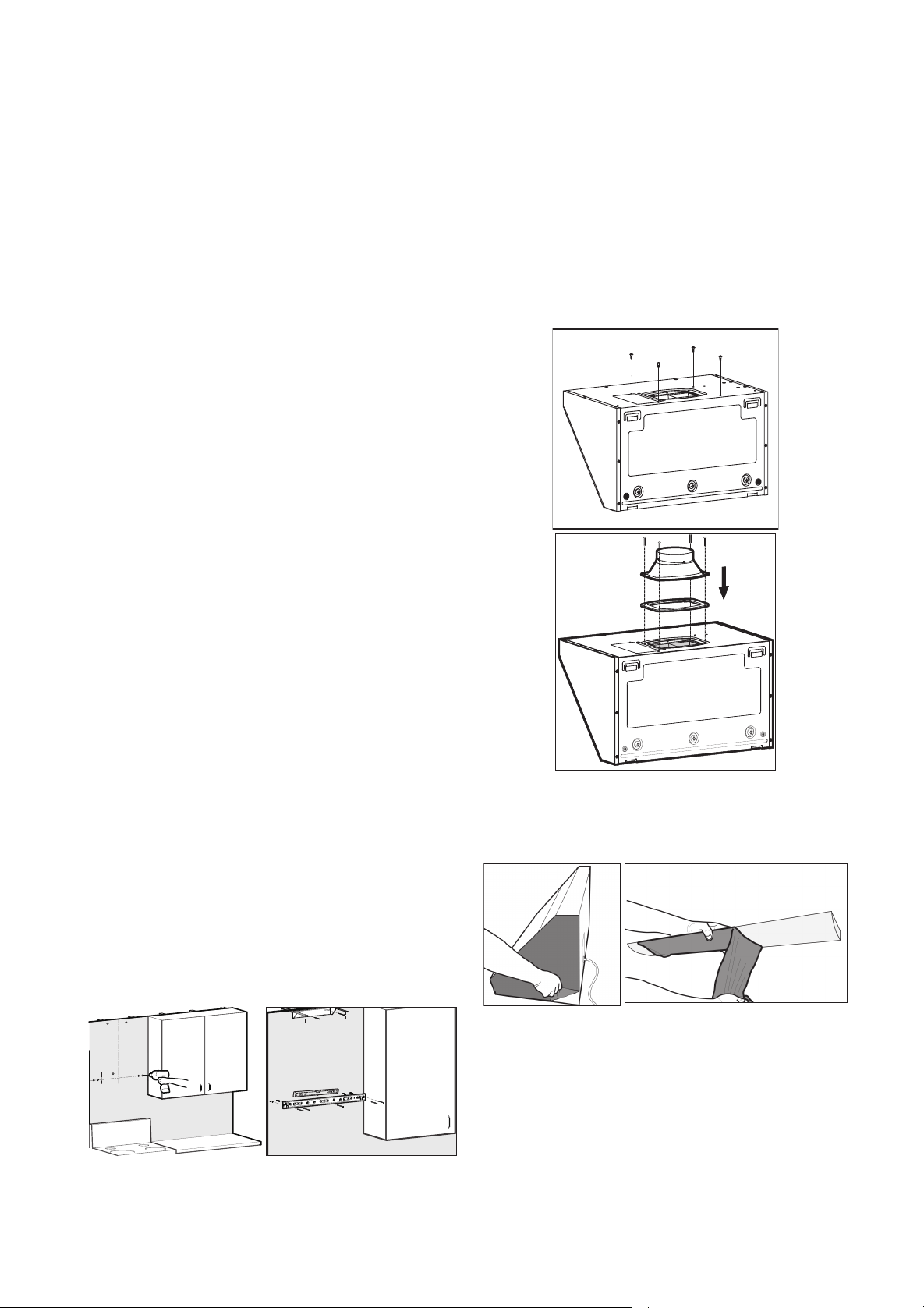
- 42 - - 43 -
at hole A and B in the drawing; also wood
screws(#10×2 9/16"(ST5×65mm)) must be xed
at bracket bores with corresponding wooden
stakes in area C.
Firstly determine the installation central point of
the range hood according to the central point
of the cooker, determine the bracket installation
location based on cooker table and mark the
place for drilling. The cooker table is about 27
7/8" (708 mm) to 30 7/8" (783 mm) away from
the central point of bracket;
The location to install the safety buffer baffle
should be 4 9/16" (115.5 mm) to the left of the
duct bracket and 2 5/16" (58.5 mm) straight up.
The location to install the decorative cover
bracket should generally be 29 15/16 " (760
mm) above the central point of the duct bracket.
If the distance between the ceiling and duct
bracket equals to or is less than the value,
secure the decorative cover bracket on the wall
right under the ceiling. If the distance is more
than the value, taller decorative covers (27
9/16" (700 mm) and 35 7/16" (900 mm) in height
respectively) need to be bought separately.
Embed the expansion tube in the punch marks:
1) Punch marks are on tiles (marble): Punch
holes (φ3/8"(φ8mm)) with an electric drill at
the marks, and embed expansion tube for
tiles(φ1/4"×1 5/16"(φ5.3×32mm)).
2) Punch marks are on plasterboards: Screw
the expansion tube for plasterboards(φ3/16"×1
5/8"(φ4×40mm)) into walls with screwdrivers at
the marks.
4. Secure the duct bracket and decorative cover
bracket to the wall with corresponding screws
and tighten the screws. Make sure the bracket
is leveled.
Caution:
One of the wood screws(#10×2
9/16"(ST5×65mm)) for duct bracket must be
fastened to the wooden beam.
5. Place the seal (notch downward) at the
air outlet of the machine and fix the outlet
housing with 4 outlet-housing bolts of
#8×3/4"(M4×18mm). Fix four outer cover bolts
of #8×7/16" (M4×10mm) at the corresponding
positions (The cover screws is provided in
the accessory bag in the packing box of the
decorative cover assembly.).
6. Remove the protective film of the stainless
steel surface and Grease Cup at both sides of
the range hood.
7. Lift and position the hood onto the mounting
screws. Make sure the hood is stable and
leveled by using a spirit level. Install the safety
buffer baffle above the hood(The safety block
is provided in the accessory bag in the packing
box of the decorative cover assembly.).
Caution:
Two installers are required to ensure
safe installation. Please install the safety stop
as required. The main function of the safety stop
is to prevent the range hood from being lifted up
accidentally, which will cause it to unhook and
potentially fall.
8. Secure the duct to the duct cover and seal the
connection with aluminum tape.
Make sure the hood is leveled. Install the Grease
Cup, and plug the appliance for a test run.
Caution:
Please run the machine and test if
the smoke pipe leaks air after it is sealed with
aluminum foil tape. The smoke pipe should be
able to be straightened as much as possible.
9. First, tear off the protective lm on the decorative
cover and fan cover, and put the decorative cover
into the fan cover. Then take up the decorative
cover and fan cover, hang the decorative cover
on the decorative cover hook, lower the fan cover
slowly, and push the decorative cover and fan
cover inward until the fan cover is fastened to the
corresponding cover screws.
10. Install the Grease Cup.
Warning:
Please wear the qualified protective
gloves in operation.
6.6 Test Run After Installation:
1. Lightly press the POWER button. Next,
lightly press the LIGHTING button. At this time,
the smoke baffle plate and lights should work
normally.
2. Lightly press the fan buttons to check the motor.
If any of the following malfunctions occurs, unplug
the hood immediately and re-check the installation
process. (If the malfunction continues, contact our
authorized service center as soon as possible.)
(1) The hood vibrates violently
.
(2) The impeller does not work
.
(3) The impeller grates while rotating.
(4) The motor makes strange sounds.
3. Lightly press the POWER button again to turn
off the fan and close the smoke bafe plate.
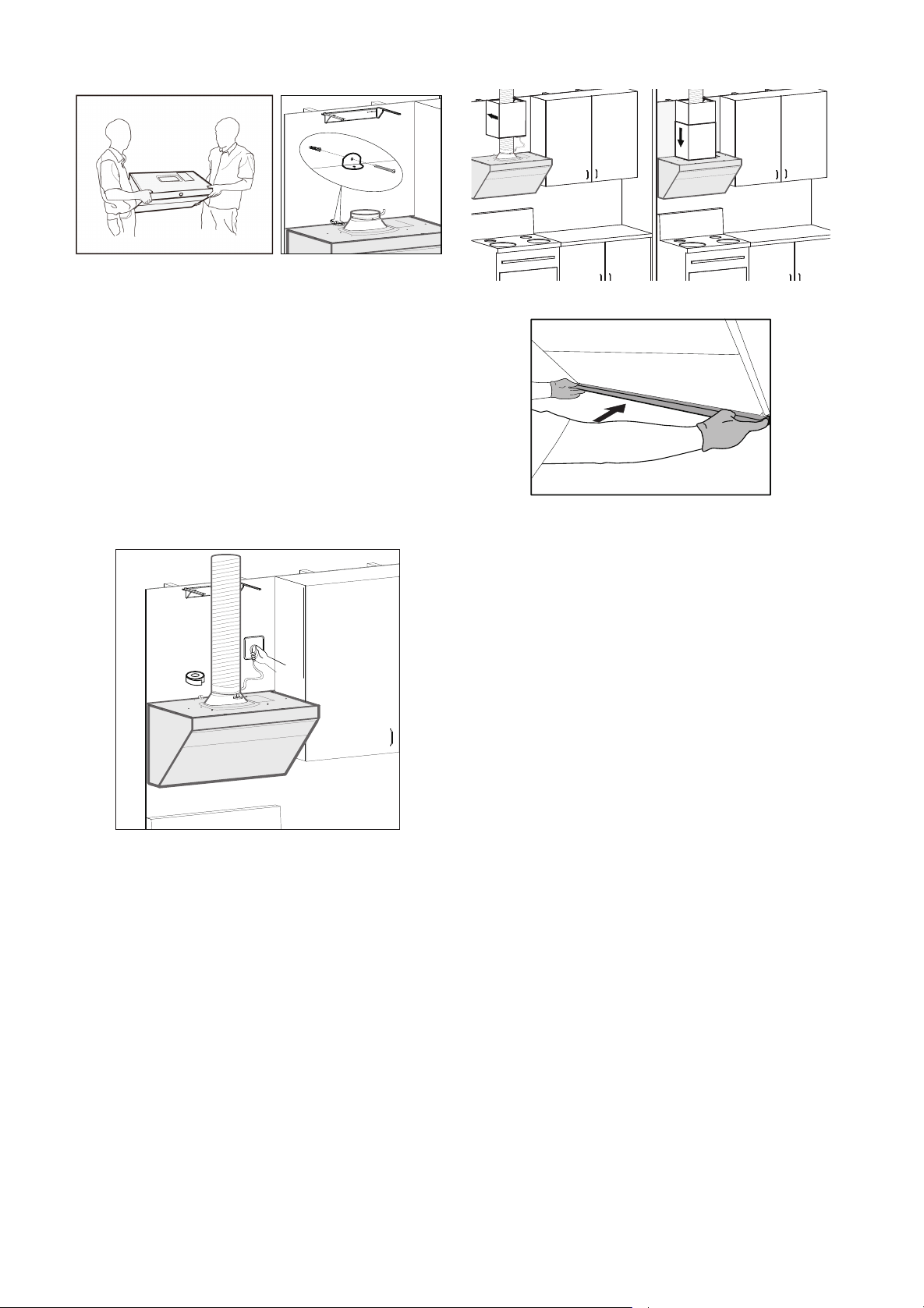

- 44 - - 45 -
Explosive ViewJQG7505/JQG7505-W
JQG9006/JQG9006-W
Power Cable
Duct Cover
Gasket
Lid of Electrical Box
Electrical Box Support Block
Power Panel
Electrical Box
Volute
Motor (Right)
Motor (Left)
Grease Guide Board
Impeller (Right)
Impeller (Left)
Tightfisted Nut (Right)
Tightfisted Nut (Left)
Air Intake Ring
Control Pressure Plate
Control Plate Component
Upper Glass
Grease Cup
Lower Glass
Glass for Smoke Baffle Plate
Grease Filter
LED
Connector Component
Push Rod Bracket
Electric Push Rod
Box
Duct Bracket
Power Cable
Duct Cover
Gasket
Lid of Electrical Box
Electrical Box Support Block
Power Panel
Electrical Box
Volute
Motor (Right)
Motor (Left)
Grease Guide Board
Impeller (Right)
Impeller (Left)
Tightfisted Nut (Right)
Tightfisted Nut (Left)
Air Intake Ring
Control Pressure Plate
Control Plate Component
Upper Glass
Grease Cup
Lower Glass
Glass for Smoke Baffle Plate
Grease Filter (Right)
Grease Filter (Left)
LED
Connector Component
Push Rod Bracket
Push Rod Cover
Electric Push Rod
Box
Duct Bracket
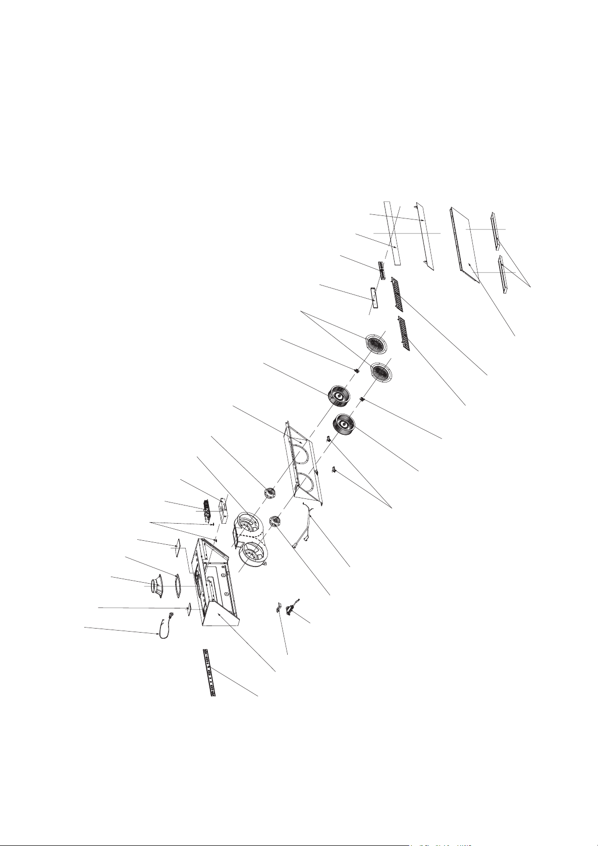

JQG7505/JQG7505-W/JQG9006/JQG9006-W

JQG7505/JQG7505-W/JQG9006/JQG9006-W

- 1 -
感谢您!
尊敬的用户,您好!感谢您选购方太公司
为
您精心制造的方太系列产品。使用前请通读本
《使用安装说明书》(以下简称说明书),此说
明书将有利于您熟悉油烟机安全信息、操作和保
养维修等,并让您享受到全新的下厨乐趣。
请您在使用前务必认真阅读说明书,并遵从
说明书要求进行使用。本说明书的操作说明对于
维持产品的良好工作状况十分重要,若因使用不
当造成产品故障,您将失去免费保修的权利,任
何直接或间接的免费保修申请将不被本公司各地
授权的服务中心所接受。同时我们建议您在质量
保证期内及保证期后,如有需要维修时请与方太
公司当地授权的服务中心联系,这对您和我们都
是非常重要的。
我们的授权的服务中心将为您提供方太公司
专业的零部件及技术支持,使您的产品得到优质快
捷的维修保障,同时让您得到最轻松细心的服务。
如果您需要服务,您将需要提供产品铭牌上
的产品型号和序列号。铭牌位置请参考以下图示
A 说明(以下配图为基础型号(JQG7505)图,
衍生型号请参照基础型号图)。
目 录
安全信息 ............................................................. 2
操作 ..................................................................... 4
清洁保养 ............................................................. 6
常见问题解答 ..................................................... 8
售后服务 ............................................................. 8
安装 ..................................................................... 8
一、安装须知 ..........................................................
8
二、产品尺寸 ..........................................................
9
三、零配件一览表 ..................................................
10
四、安装工具 ..........................................................
11
五、安装步骤 ..........................................................
11
六、安装后调试 ......................................................
17
为确保方太产品的安全和高效使用,请注意产品
说明书中以下突出显示信息:
重要提示——强调非常重要的信息。
注意——表示如不遵守指导说明则可能出现轻微
人身伤害或产品损坏。
警告——标明如不遵守预防措施则可能导致严重
人身伤害或死亡等危险。
产品特征和参数会在无通知情况下随时更改,并且可
能与此说明书略有不同。请访问我们的官网,获取最
新信息。
方太美国分公司
* 地址:6 Campus Dr, Suite 210, Parsippany, NJ 07054
* 电话:888-315-0366
* 官网: us.fotileglobal.com
* 服务邮箱:[email protected]
方太加拿大旗舰店
* 地址:8365 Woodbine Ave,Markham, L3R2P4
* 电话:844-315-0315
* 官网:ca.fotileglobal.com
* 服务邮箱:[email protected]
美国微信客服
加拿大微信客服
加拿大微信公众号
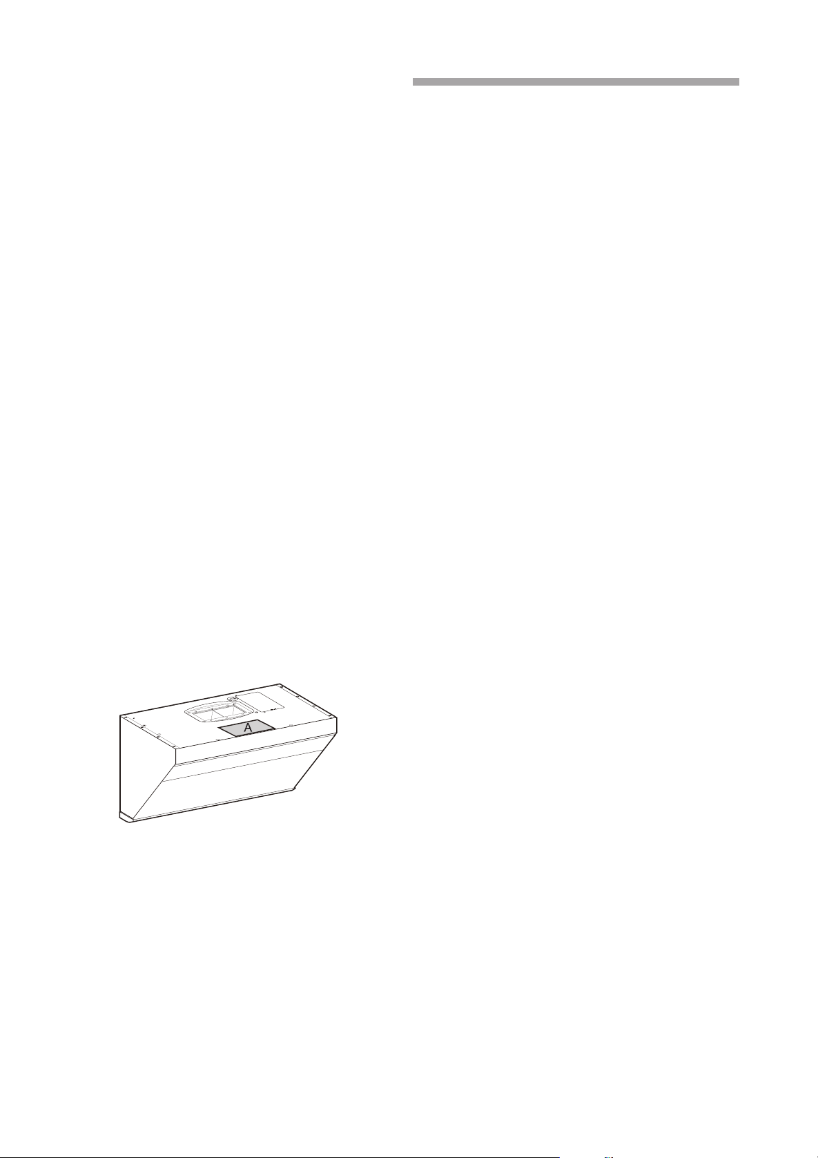
- 1 -
感谢您!
尊敬的用户,您好!感谢您选购方太公司
为
您精心制造的方太系列产品。使用前请通读本
《使用安装说明书》(以下简称说明书),此说
明书将有利于您熟悉油烟机安全信息、操作和保
养维修等,并让您享受到全新的下厨乐趣。
请您在使用前务必认真阅读说明书,并遵从
说明书要求进行使用。本说明书的操作说明对于
维持产品的良好工作状况十分重要,若因使用不
当造成产品故障,您将失去免费保修的权利,任
何直接或间接的免费保修申请将不被本公司各地
授权的服务中心所接受。同时我们建议您在质量
保证期内及保证期后,如有需要维修时请与方太
公司当地授权的服务中心联系,这对您和我们都
是非常重要的。
我们的授权的服务中心将为您提供方太公司
专业的零部件及技术支持,使您的产品得到优质快
捷的维修保障,同时让您得到最轻松细心的服务。
如果您需要服务,您将需要提供产品铭牌上
的产品型号和序列号。铭牌位置请参考以下图示
A 说明(以下配图为基础型号(JQG7505)图,
衍生型号请参照基础型号图)。
目 录
安全信息 ............................................................. 2
操作 ..................................................................... 4
清洁保养 ............................................................. 6
常见问题解答 ..................................................... 8
售后服务 ............................................................. 8
安装 ..................................................................... 8
一、安装须知 ..........................................................
8
二、产品尺寸 ..........................................................
9
三、零配件一览表 ..................................................
10
四、安装工具 ..........................................................
11
五、安装步骤 ..........................................................
11
六、安装后调试 ......................................................
17
为确保方太产品的安全和高效使用,请注意产品
说明书中以下突出显示信息:
重要提示——强调非常重要的信息。
注意——表示如不遵守指导说明则可能出现轻微
人身伤害或产品损坏。
警告——标明如不遵守预防措施则可能导致严重
人身伤害或死亡等危险。
产品特征和参数会在无通知情况下随时更改,并且可
能与此说明书略有不同。请访问我们的官网,获取最
新信息。
方太美国分公司
* 地址:6 Campus Dr, Suite 210, Parsippany, NJ 07054
* 电话:888-315-0366
* 官网: us.fotileglobal.com
方太加拿大旗舰店
* 地址:8365 Woodbine Ave,Markham, L3R2P4
* 电话:844-315-0315
* 官网:ca.fotileglobal.com
* 服务邮箱:service@fotileca.com
美国微信客服
加拿大微信客服
加拿大微信公众号

- 2 - - 3 -
安全信息
为避免任何对油烟机的意外风险和损害,请在开
始安装和使用前仔细阅读此产品说明书。只有这
样您才能安全正确地操作此产品,降低火灾、电
击或者人身伤害等风险。请保留此产品说明书,
以供今后使用或后续用户使用。
重要提示:
本产品仅用于家庭室内使用,不可用于室外。
仅按照制造商的方式使用本产品,若您在室外
或特殊场合使用本产品,方太将不承担任何责
任。如果您有任何问题,请联系方太授权的服
务中心。
使用此新产品之前请开封检查此产品是否受
损,如果发现此产品有明显的损坏,请勿安装
使用,请您立即联系方太授权的服务中心。
请保持此油烟机远离石膏板粉末、建筑尘埃等
物质。
请仅以本说明书指定的方式使用。请不要在无
人看管情况下运行此产品。如有疑问,请联系
方太授权的服务中心。
作为使用者,您对家中的油烟机负有清洁保养
和正确使用的责任。
根据实际条件清理金属油网。
油烟机电机有热过载功能,此功能在电机过热
时会自动关闭电机,当电机冷却下来后会重新
启动,如果电机不断关闭、重启,请联系方太
授权的服务中心。
油烟机若长期不用,请拨下电源插头。
请确保此产品正确的安装和维修。此产品必须
符合所有适用的规范和标准,包括防火建筑的规
范和标准,由合格技师进行正确安装和接地。安
装人员负责确保此产品在其安装位置正常工作。
当烟机处于排气模式时,请确保烟机安装止逆阀。
仅用于一般排气使用。请不要使用此油烟机排
放有害或爆炸性材料和气体。
产品自身不可燃。
为降低火灾危险,所有排烟管、烟道和设备应
是不可燃的,请仅使用金属管道。绝不用可燃
塑料或纸张覆盖油烟机。
保修服务须由方太公司认可的服务机构或人员
执行。如私自拆机维修,产品将不享受保修。
请阅读油烟机上的规格标签,以便了解更多信
息和要求。
如用户房屋密封,安装有大功率烟机,建议安
装补充空气装置。方太油烟机的配置,建议密
封性高的新房用户安装补充空气装置。如所属
州或地区有相关法律规定要求,建议遵守相关
法律规定要求安装相应补充空气装置。
本产品仅限于美国和加拿大使用。
注意:
若当地适用的法规包含更为严格的安装和认证
要求,上述要求优先于此文档中相应的要求,
并且安装人员同意遵守这些要求。
油烟机使用环境的温度不能超过104
℉
(40℃)。
请不要在此产品上放置任何物品,产品上放置
的东西可能跌落或倾倒。例如把调料瓶放置在
油烟机顶部,倾倒后可能造成液体流入产品内
部,导致带电部件损坏,造成不必要风险。若
因此造成的产品损坏,本公司不承担免费保修
责任。
请及时清理油杯中的废油,防止溢出。油杯中
所收集的废油请勿食用!请不要在油杯中放置
易燃物,如保鲜膜、厨房纸等。
当在墙上或天花板上开凿或钻孔时,请注意不
要损坏电线、水管、燃气管道以及其他隐藏的
设备。
请遵照加热设备厂商的指导方针和安全标准,
如美国消防协会,美国采暖、制冷和空调工程
师协会和地方法规指定当局发布的指导方针和
安全标准。同时要遵照消防等管理部门颁布的
安全标准。当燃气灶在空烧时,会产生大量热
量 , 安装在其上方的油烟机可能会受损或着火 ,
请仅在有锅具时操作燃气灶。
为避免任何可能对产品的损害,请确保实际电
压和频率与本说明书中阐明的一致。
请确保使用我司提供的标准配件,以防油烟机
意外跌落;墙上开的洞应精准符合膨胀管的尺
寸,否则,油烟机可能松动跌落。
本公司产品上使用了钢化玻璃,玻璃的钢化机
理决定这种玻璃存在极小概率的自爆。一旦发
生非使用不当的自爆,我公司承诺免费更换该
配件。钢化玻璃在以下情况,发生破裂的几率
可能会大大提高,请避免发生:例如用炊具或
其他硬物敲击玻璃,特别是敲击玻璃四个角部;
打开油烟机周围橱柜门时撞击到玻璃;玻璃处
于过冷和过热、冷热交替严重的环境等情况。
擅自改装此产品会产生风险。
警告:
触电危险
有缺陷的产品可能引起电击,绝不启动有缺陷的
产品。如发现问题请将此产品从电源上拔下或切
断总电源,并请联系方太授权的服务中心。
此产品应使用专用电源插座,并且专用电源插
座应有可靠接地,因为电源线中途连接、使用
延长线以及多口配线器时易发生触电、插头插
座发热以及火灾。请确保由专业电工在严格按
照所在国家和地方的电力法规进行操作 , 接线
以前,请先关闭电源并采取合理措施防止电源
开关自动闭合。
禁止使用 125V 以上的交流电,以免引起危险。
禁止将此产品安装在浴室或湿度高的场所,这
样容易造成触电。
如果电源线损坏,请联系授权服务提供商或
合格技术人员进行更换。
请不要对电源线进行改制、拉伸结扣以及施加
重物、挤压等,否则易导致电源线破损而发生
触电和火灾。
严禁电机、开关、接插件等电器部件沾水 , 禁
止用水冲洗油烟机。油烟机被水淋湿后,请不
要使用 , 如果使用会导致漏电、触电。
禁止私自改动产品内部布线 , 否则有可能发生
异常动作导致人体受伤。不当修理可能发生触
电、火灾等危险。
在清洗产品、提供安装或维修服务之前,必须
切断电源,以免触电。
请不要使用任何可能导致电击的高压清洁剂或
蒸汽清洗器。
请不要用潮湿的手触摸电源插头电器部件以及
操作电源开关,否则易发生触电。
接地说明
此产品必须接地。如果发生短路,接地可以降
低电击的危险。此产品配有接地插头的电源线。
插头必须插在合理安装并接地的电源插座上。
不合理接地会导致电击危险。
如并未完全理解接地说明或者对产品是否已合
理接地存在疑虑,请咨询合格电工。
请不要使用延长线。如果电源线过短,请合格
电工在产品附近安装电源插座。
火灾危险
为降低火灾危险并合理排气,请总是外排。请
不要将废气排到墙体、天花板、阁楼、窄小空
间或车库中。
如果不按本说明书规定的方法清洗 , 油烟机有
起火的危险。
热油和油脂会快速点燃,绝不让热油或油脂处
于无人看管状态。
油网中油脂沉淀物可能着火,请定期清洗油网。
请勿在无油网的情况下操作此产品。
油网中的油脂沉淀物可能着火,绝不在此产品
附近使用明火。请不要在使用固体燃料(比如
木头或煤)的加热设备附近安装此产品。禁止
有飘飞的火花。
请避免在烟机下方使用会产生火焰的食品。
为降低灶台油火风险:
1. 绝不使灶台表面的器具在无人看管下高档位
运行。溢锅造成冒烟和可能起火的油脂外溢,
请在低档或中档设置下缓慢加热油脂。
2. 烹饪时请总是开启烟机。
3. 请清洁油烟机,叶轮、滤网上或在排烟管道
里不应积油。
4. 请使用合适尺寸的锅具。请总是使用与灶台
表面的器具尺寸吻合的炊具。
为降低灶烤一体机上方油火对人身伤害的危
险,请遵守以下说明:
1. 用合身的锅盖、烤板或金属托盘扑灭火焰,
然后关闭灶具。注意谨防烫伤。如果火焰未
立即熄灭,请疏散并报火警。
2. 油锅着火时,请立即关闭油烟机 ( 油烟机的
运行会助燃火势 )。立即采用有效的灭火措
施,如用金属封盖盖住明火、关闭燃气总阀、
使易燃物远离明火等。
3. 绝不拿起着火的锅具,您可能被烫伤。
4. 请勿用水,包括湿抹布或毛巾灭火,这样会
导致猛烈的蒸汽喷发。
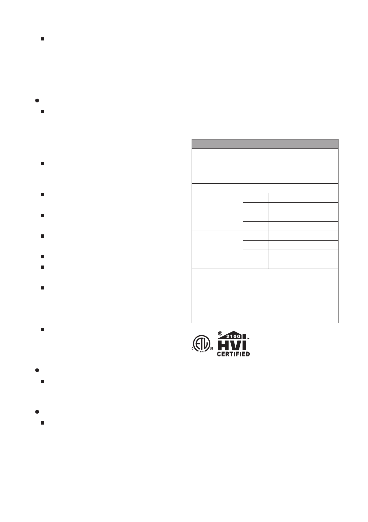
- 4 - - 5 -
仅在以下条件使用灭火器:
1. 当您上过基础的灭火器课程,并且已经知
道如何操作;
2. 当火较小并且控制在火源处;
3. 当您已打火警电话;
4. 当您背向出口时可救火。
人身伤害危险
此产品不适用于(包括儿童在内)身体、感知
或精神能力减弱或缺乏经验或知识的人群,除
非在对其安全负责的人监督或指导如何安全使
用此产品的情况下。孩童应受监管,确保其不
玩弄此产品。
油烟机可能有非常锋利的边,在进行安装、清
洁或修理时,谨防被油烟机内金属板快口等划
伤和擦伤。应佩戴合格的防护手套。
操作中可触及部分会变得很烫。绝不触摸变烫
的部分。保持儿童在安全距离以外。
请勿触摸已经开启或刚关闭不久的灯,以免烫
伤。
油烟机叶轮运转时,禁止将手指或其他物品放
入其中,以免造成伤害。
此产品不应和外部钟表计时器或遥控器配合使用。
不正确的维修很危险。仅合格的售后服务技师
才可进行维修。
出现异常现象时,请关闭产品电源,拨下电源
插头或者切断总电源,马上与方太授权的服务
中心联系。异常状态下连续运转易发生触电、
火灾等危险。
本产品可能会使您暴露于化学物质,加利福尼
亚州已知该化学物质可致癌和出生缺陷或其
他生殖危害。如需了解更多信息,请访问:
www.P65Warnings.ca.gov
窒息危险:
包装材料对儿童有危险。绝不允许儿童玩弄包
装材料,这可能会产生窒息事故,所以请让包
装材料远离儿童,包装材料不是玩具。
死亡危险:
烟道倒灌有中毒危险。当此产品在排气模式下
运行,同时依赖于房内空气的加热设备也在运
行时,请总是确保屋内有充足空气保证充足燃
烧和排气。请通过烟道(烟囱)排放废气,防
止废气倒灌。
因使用不当或误操作造成的伤害厂商不负责
任。
操作
警 告
1. 防过猛过重操作按键;
2. 防灶具空烧;
3. 防通电拆卸和违嘱拆卸;
4. 防油杯油满外溢;
5. 防非专业人员拆检;
6. 禁止炉火直接烘烤油烟机。
产品信息
操作
1. 操作界面说明
电源感应
窗口
锁屏 延时 照明
强档 /
超强档
中档 弱档 感应
窗口
型号 JQG9006/JQG9006-W
产品尺寸 L*D*H
35 7/8 × 18 7/16 × 17 7/16 "
(910 × 467 × 442 mm)
净重 70.1 Ibs(31.8kg)
电压 / 频率 120V/60Hz
整机额定输入功率 210 W(包含灯功率 3W × 2 )
噪音
超强档 56dB(A)
高档 53dB(A)
中档 48dB(A)
低档 38.5dB(A)
最大静压 560Pa
注:1. 上表 dB 噪 音 按 照 IEC60704 标准, 为 声 压 级 噪
音,对应声功率级噪音为:超强档 68dB(A)、高档
66dB(A)、中档 60dB(A)、低档 52.5dB(A)。
2. 噪音等参数可能存在 10% 以内的偏差。
型号 JQG7505/JQG7505-W
产品尺寸 L*D*H
29 7/8 × 18 7/16 × 17 7/16 "
(758 × 467 × 442 mm)
净重 63.9 lbs(29Kg)
电压 / 频率 120V/60Hz
整机额定输入功率 210 W(包含灯功率 3W × 2 )
风量 (CFM)(HVI)
超强档 600
高档 540
中档 420
低档 230
噪音
超强档 56dB(A)(7.2Sones)
高档 53dB(A)(6.2Sones)
中档 48dB(A)(3.9Sones)
低档 38.5dB(A)(1.2Sones)
最大静压 560 Pa
注:1. 上 表 dB 噪 音 按 照 IEC60704 标 准, 为 声 压 级 噪
音,对应声功率级噪音为:超强档 68dB(A)、高档
65dB(A)、中档 60dB(A)、低档 52.5dB(A)。
2. 上表 Sones 噪音按照 HVI-915-2015 标准,在 HVI
认可美国实验室测得。
3. 噪音等参数可能存在 10% 以内的偏差。
HVI-2100 CERTIFIED RATINGS comply with
new testing technologies and procedures prescribed
by the Home Ventilating Institute, for off-the-shelf
products, as they are available to consumers.
Product
performance is rated at 0.1 in. static pressure, based
on tests conducted in a state-of-the-art test laboratory.
Sones are a measure of humanly-perceived loudness,
based on laboratory measurements.
2. 操作过程说明
(1) 手势功能:挥手 快速经过两端感应窗口,
隔烟屏自动开启,油烟机在强档运行,照明
灯打开;再次挥手 快速经过两端感应窗口,
油烟机所有功能关闭,按键灯熄灭,隔烟屏
自动闭合,油烟机处于关机状态。在关机状
态下,同时按下 照明键和 中档键 5 秒,
开启 / 关闭手势感应功能。
(2) 电源键:在关机时轻触一下,油烟机进入
待机状态,电源键全亮,其他按键指示灯半
亮;在工作状态下,轻触一下,所有功能关闭,
按键灯熄灭,隔烟屏自动闭合,油烟机处于
关机状态。
除锁屏键外,其余按键在电源键开启状态下
才有效。
(3) 强档 / 超强档键:轻触一下,隔烟屏自动
开启,风机启动, 强档 / 超强档指示灯全
亮,油烟机在强档运行;再轻触一下强档 / 超
强档键 ,电机停止运转, 强档 / 超强档
指示灯恢复至半亮;长按 2s 强档 / 超强档键
, 强档 / 超强档指示灯全亮绿灯,油烟
机在超强档运行,再次长按 2s 强档 / 超强档键
,油烟机退回到强档运行, 强档 / 超强档
指示灯全亮;再轻触一下强档 / 超强档键 ,
电机停止运转, 强档 / 超强档指示灯恢复
至半亮。
(4) 中档键:轻触一下,隔烟屏自动开启,风
机启动, 中档指示灯全亮,油烟机在中档
运行;再轻触一下中档键 ,电机停止运转,
中档指示灯恢复至半亮。
(5) 弱档键:轻触一下,隔烟屏自动开启,风
机启动, 弱档指示灯全亮,油烟机在弱档
运行;再轻触一下弱档键 ,电机停止运转,
弱档指示灯恢复至半亮。
(6) 照明键:轻触一下,隔烟屏自动开启,照
明灯打开, 照明指示灯全亮;再轻触一下,
照明灯关闭, 照明指示灯 恢复至半亮。
(7) 延时键:在油烟机电机工作时,轻触一下 ,
延时键指示灯全亮,油烟机进入 2 分钟延
时,2 分钟到后,所有功能关闭,隔烟屏自
动闭合,油烟机关机。
在延时状态时,轻触延时键 1 次,则退出
延时, 延时键指示灯恢复至半亮,油烟机
保持当前工作状态。
在延时状态时,轻触除延时按键外的任意键 1
次,则退出延时, 延时键指示灯恢复至半亮,
执行所轻触按键的功能。
当油烟机不工作时,延时键 无效,如果按
下会发出警报声。
(8) 锁屏键:在油烟机风机不运行时,长按锁
屏键 2 秒钟,机器“滴”响一声后, 锁
屏键指示灯全亮闪烁,所有按键被锁住,触
按无效;再长按锁屏键 2 秒钟,锁屏功能
取消。在油烟机风机运行时,锁屏键无效,
如果按下会发出报警声。
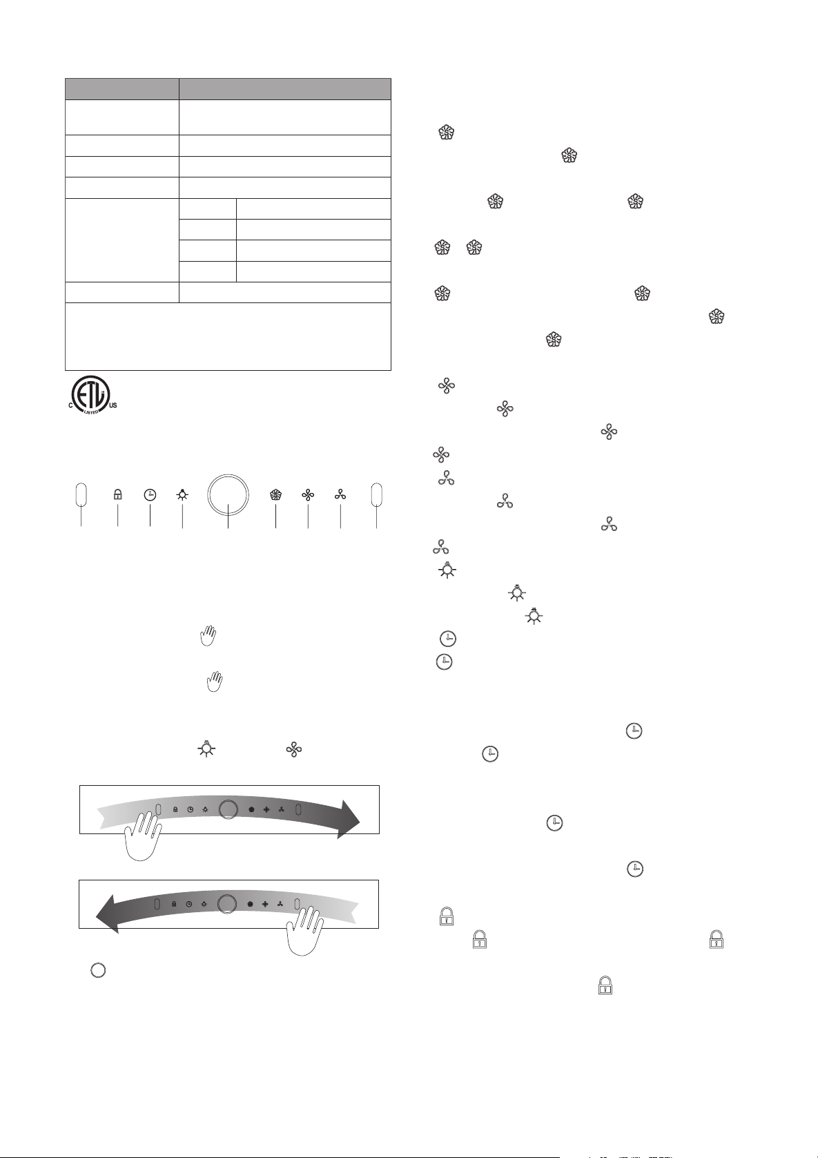
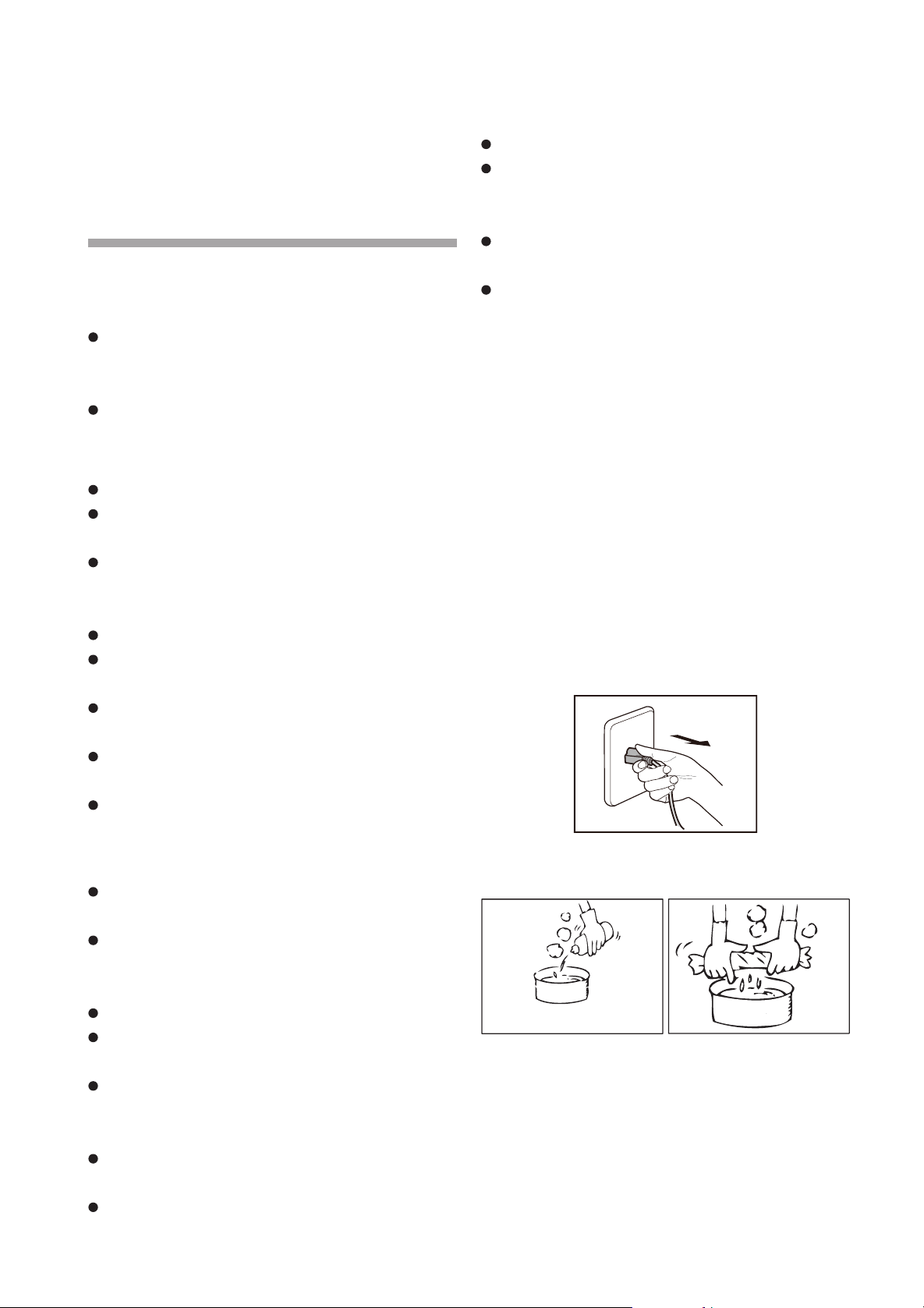
- 6 - - 7 -
清洁保养
重要提示:
清洁完油网后,请将油网重新安装归位。请勿
在没有油网的情况下操作油烟机,可能会有安
全隐患。
以下配图为基础型号(JQG7505)图,衍生
型号请参照基础型号图。
注意:
腐蚀造成损坏危险。
烹饪时请总是打开油烟机,以防冷凝。冷凝可
造成腐蚀损坏。
清洁不当会造成表面损坏,请仅沿不锈钢表面
纹路进行清洁,请不要使用任何不锈钢清洁剂
清洁控制装置。
强效或磨砂清洁剂会造成表面损坏。
请更换故障 LED 灯,以免其余灯过载。
警告:
如果不按此说明书规定的方法清洗,油烟机有
起火的危险。
清洁时应防止电机、各控制键等电气部件进水。
水气进入电路会造成损坏危险。
切勿使用汽油、酸性物质、苯、溶剂或任何其
他化学药剂清洗油烟机。
电击危险:
渗透的水气可能导致电击。清洁、维修油烟机前,
请拨下电源插头或者切断总电源,以免触电。
请不要使用任何可能造成电击的高压清洁机或
蒸汽清洁装置。
火灾危险:
油网及油杯中油脂沉积物可能着火。
请不要在油杯中放置易燃物,如保鲜膜、厨房
纸等。
不要让油过多聚集并定期清洁油杯及其他可能
积聚积油的部件。
人身伤害危险:
在移动油烟机进行安装、清洁或者修理前,务
必切断电源,以免触电。
油烟机可能有非常锋利的边,在进行安装、清
提示:
1. 待机状态下 2 分钟没有操作,油烟机会自动关机;
2. 建议蒸煮时开启吸油烟机,保持厨房空气清新,
否则较多水蒸气经过感应窗口可能会触发手势
功能。
洁或修理时,以防被油烟机内金属板快口等划
伤和擦伤。应佩戴合格的防护手套。
当风机在使用时,禁止将手放入风机运转区域。
此产品在操作过程中会发热,尤其 LED 灯附近。
请在清洁前等待产品冷却。请不要触摸运行中
或刚结束运行的 LED 灯 , 可能有烫伤危险。
如需深度清洁油烟机,请联系方太授权的服务
中心。
为了您更加舒适地使用此产品,请经常对油烟
机表面进行清洁。
1. 如果油烟机表面看上去有污点,使用中性清
洁剂清洁污点,并避免清洁剂接触各控制键。
把清洁剂滴至污点之处并短暂停留 ( 清洁剂
不要在机体上停留过长,那样将造成损害 ),
使用柔软的抹布将污点擦去,用微湿的毛巾
将清洁剂除去,然后再用柔软的干毛巾将机
体擦干。
2. 不要让污渍在油烟机表面停留时间过长。
3. 如不注意将含盐的溶液、消毒剂、漂白粉以
及其他清洁剂沾到不锈钢面板,应立即用微
湿的毛巾擦拭,然后用干布擦干。
警告:请不要使用清洁球、刷子以及粗布等粗糙
物进行清洁,以防止划伤机体表面。
清洗前准备:
1. 拔掉油烟机电源插头,或关闭插座电源;
2. 把灶具上器具清理干净;
3. 请准备好中性洗涤剂和软布 ( 软刷 );
中性洗涤剂
软布
清洗清洁表面、油杯和油网
(此操作可由用户自行操作)
1. 清洗油烟机表面
2. 水平取出油杯并清洗。
警告:为了您及家人的安全,请定期清洁油杯内
积油和油杯外表面沉积物,否则会有引起火灾的
危险。操作时请带防护手套操作。
3. 轻触电源键,再轻触灯键,打开隔烟屏。
4. 双手拉住左右两侧的油网孔,向外拉即可卸下
油网。
★建议:为了您与家人的健康,请定期清洗油网。
油网可放进洗碗机里清洗。
警告:请戴防护手套操作。
更换 LED 灯步骤:
1. 轻触电源键,再轻触灯键,打开隔烟屏;
2. 拔掉油烟机电源插头,或关闭插座电源;
3. 用小型一字螺丝刀轻微插入灯边缘,下撬并取
出灯组件;
4. 拆开灯连接线,更换整个 LED 灯。
所用灯为 LED 灯:灯功率为 3W,电压范围为
8.5~12V,灯尺寸为宽度 2 13/16”(70mm)/ 深
度 7/8”(21mm)/ 高度 3/4”(19mm)。
电击危险:在更换 LED 灯前,请先拨下电源插
头或者切断油烟机插座电源,以免触电。
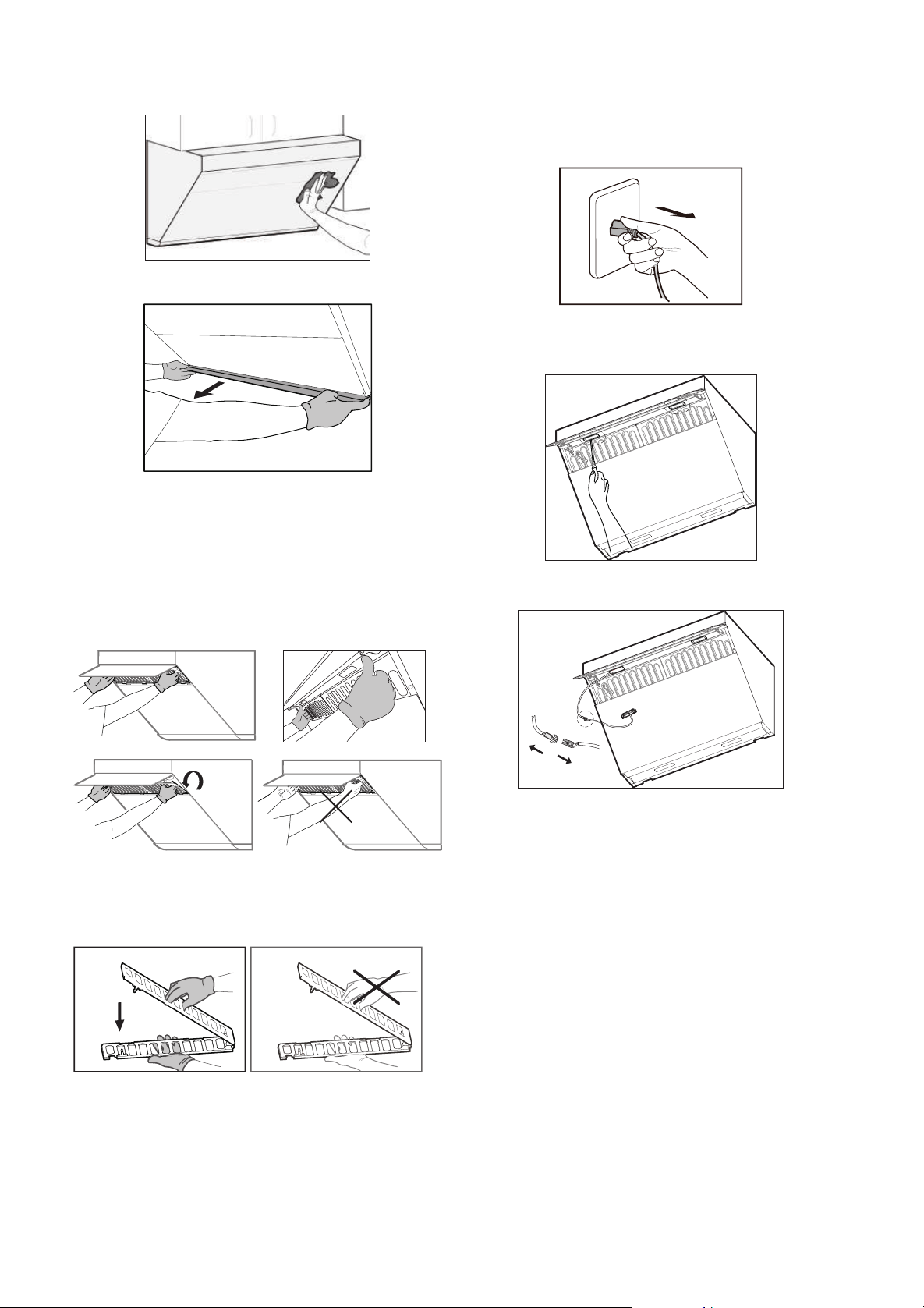
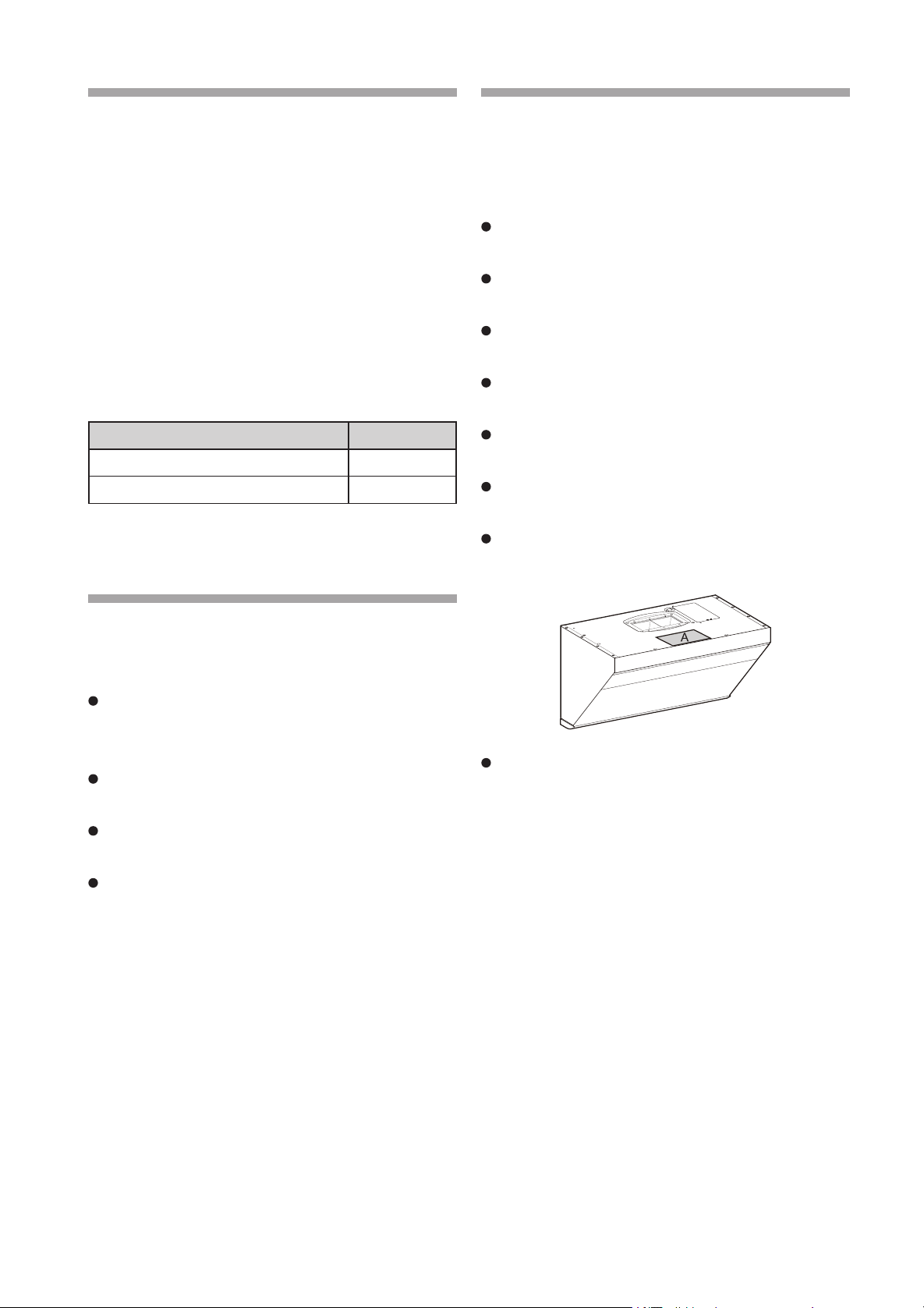
- 8 - - 9 -
常见问题解答
警告:电击危险
不正确维修很危险。仅由方太授权的服务中心或
有资质的电工才可维修和更换受损电源线。如果
产品有缺陷,请拨下电源插头或者切断油烟机插
座电源,以免触电。请联系方太授权的服务中心。
在更换 LED 灯前,请先拨下电源插头或者切断
油烟机插座电源,以免触电。
如果您在使用中发现异常状况,请停止使用,请
拨下电源插头或者切断油烟机插座电源,检查以
下内容:
故障现象 可能原因
按开关,油烟机不工作,灯不亮 未接通电源
电机转动但灯不亮 LED 灯损坏
当上述故障排除后,油烟机仍不能正常工作,请与
方太授权的服务中心联系维修。
售后服务
警告
如油烟机在使用中发生异常状况,请停止使用,
拔下电源插头或者切断油烟机插座电源,请与
方太授权的服务中心联系。
只有经过专业培训的、并获得油烟机维修资质
的维修人员,才能对油烟机进行维修。
其他人员不得擅自维修油烟机,以免造成严重
后果,而且产品将不享受保修。
下列项目不属于免费保修范围,将实行收费维修:
1. 用户搬运、安装、使用、维护、保管不当而损
坏的。
2. 超出正常使用条件,强行使用本产品造成的故
障和损伤(例如电压超出 132V 或低于 104V 而
损坏的)。
3. 自行或非方太指定服务人员或服务机构安装和
拆修的产品。
4. 购买凭证和保修卡信息与产品不符的。
5. 因不可抗拒力造成产品损坏的(如自然灾害、
战争等)。
6. 不根据“使用说明书”的规定使用,造成产品
故障或损伤的。
注意 :
在安装以前,请仔细阅读所有的说明。特别请
注意以下事项 :
1. 如果您正在对您的厨房进行装修,请勿将油烟机
暴露在外。因为建筑材料、灰尘、油漆、涂料以及
它们所挥发的气体,会使油烟机表面产生腐蚀以及
失去光泽。建议在厨房装修完毕后再安装油烟机。
2. 如果在安装油烟机前,需要移动燃气灶,则在
移动燃气灶之前,请先关闭燃气总阀门。
3. 油烟机排出的废气不能排放到用于排出燃烧燃气
或其他燃料的烟雾使用的热烟道中。
4. 因油烟机的尺寸较大和重量较重,建议两位安装
人员安装。由于本油烟机的安装程序复杂,因此需
要专业安装维修人员按照此说明书进行安装。
5. 产品固定后,插头应在可接触位置。
6. 安装时须尽量保证机身水平。
7. 安装完毕,请确认油烟机运转无异常现象。
安装
一、安装须知
重要提示:
请在安装前阅读所有安装指导,保存此说明书
以备当地巡检参考和日后参阅。
此产品安装必须遵守国家电力法,也要遵守各
个州、市政和地方的法规。
请为此产品配备合适的断路器,并在安装时将
产品可靠接地。
必须根据产品铭牌上提供的电压、频率和安培
给产品配备合适的电压、频率和安培额定值。
此安装必须由方太授权的服务中心或其认可的
安装人员完成。
安装油烟机前请记录下产品型号和序列号。产
品型号和序列号请参考以下图示 A 说明。
以下配图为基础型号(JQG7505)图,衍生型
号请参照基础型号图。
警告:
为降低火灾、电击或人身伤害危险,请注意以
下事项:
1. 油烟机的安装以及电路的设置必须要由有经验的
专业人员进行,非专业人员请勿安装。在安装时要
遵守所有相关的法规、标准,包括与火灾有关的说
明。正确安装是安装人员的责任。由于安装不当导
致的产品故障不包括在方太保修范围内。
2. 为确保安全和安装顺利,请使用随机附件进行安
装;安装膨胀管时,膨胀管与墙孔的配合一定要紧密,
严禁钻孔过大,以免膨胀管松动,造成意外跌落!
3. 油烟机应使用专用电源插座,并且专用电源插座应
有可靠接地。因电源线中途连接、使用延长线以及多
口配线器时易发生触电、插头插座发热以及火灾。
装电线前请切断电源,请确保采取合理措施避免意
外电源接通。
4. 安装时不能接通电,应在主电源箱中关闭电源。
如果电源线损坏,必须由制造厂商或其服务代理提
供的单独特配电源线或套件进行替换。
5. 用户自行安装易发生触电、脱落、起火等危险。
非专业人员请勿拆卸、安装及维修油烟机。
人身伤害危险:
在移动油烟机进行安装、清洁或者修理前,务
必切断电源,以免触电。
油烟机可能有非常锋利的边,在进行安装、清
洁或修理时,应佩戴合格的防护手套,以防被
油烟机内金属板快口等划伤和擦伤。
安装前的警告 :
为了不对油烟机造成损害,请确保不要让杂物
等进入排风口。
直线、较短的出风管布置将使得油烟机的排烟
更加顺畅。
尽量避免使用过长以及有较多弯道的出风管,
使用这些管道将影响油烟机的排烟效果。
出风管与墙孔的连接处使用管道胶严格进行密
封。必须确保出风管与出风罩连接牢固,并用铝
箔胶带密封。
墙洞过小会影响排烟效果,在保证安全的前提
下,建议扩孔至 6"(152.4mm) 或以上。
本产品上使用的都为公制尺寸螺钉,请不要随
意使用不符合规格要求的螺钉。
二、产品尺寸
187/16"
(467mm)
297/8"(758mm)
(JQG7505/JQG7505-W)
357/8"(910mm)
(JQG9006/JQG9006-W)
墙面安装
安装油烟机的墙壁要有足够的支撑强度,对于中
空墙壁,中空板实心层的厚度必须大于 1 3/16"
(30mm)以上 , 对于混凝土墙壁可直接打安装孔。
整机必须牢固安装在墙壁上。
安装烟管
人身伤害危险:在油烟机进行安装、清洁或者
修理前,务必切断电源,以免触电。油烟机可
能有非常锋利的边,在进行安装、清洁或修理
时,应佩戴合格的防护手套,以防被油烟机内
金属板快口等划伤和擦伤。
当在墙上或天花板上开凿或钻孔时,请注意不
要损坏电线以及其他隐藏的产品。
安装管道的烟机必须总是外排。
为了避免火灾的发生,请将废气排到室外。请
不要将废气排到墙面或天花板内空间,或者阁楼、
窄小空间或车库中。
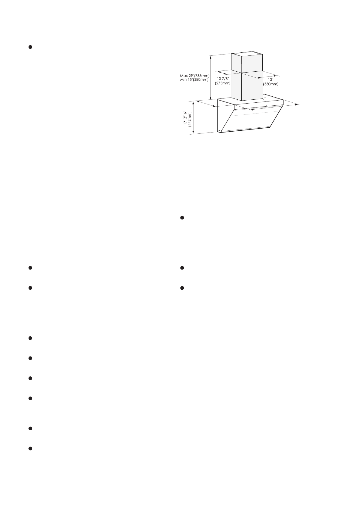
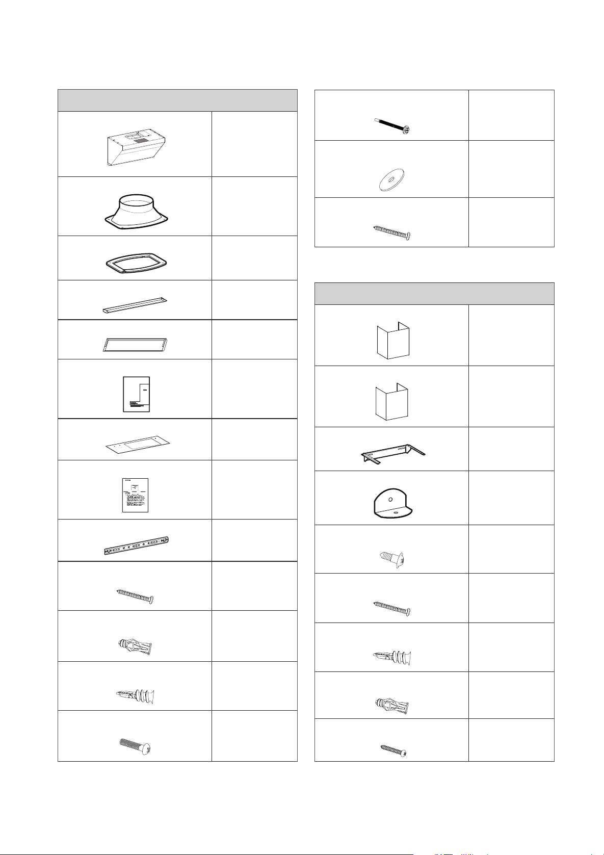
- 10 - - 11 -
三、零配件一览表
装箱单
标准配置
主机
1台
出风罩
1个
密封垫
1个
油杯(JQG7505/JQG7505-W)
1个
油杯(JQG9006/JQG9006-W)
2个
使用说明书
1本
开孔尺寸纸
1张
保修卡
1张
主机挂钩
1个
挂钩螺钉
#8×1 7/16"(ST4.2×36mm)
4颗
瓷砖膨胀管
φ1/4"×1 5/16"(φ5.3×32mm)
4个
灰板膨胀管
φ3/16"×1 5/8"(φ4×40mm)
4个
出风罩螺钉
#8×3/4"(M4×18mm)
4颗
五、安装步骤
为保证油烟机使用安全和最佳吸油烟效果,
建议安装高度:从台面到油烟机顶部不得低
于 29 9/16"(750mm), 最 高 不 要 超 过 32
1/2"(825mm)。此安装高度只适用于电灶,如
果吸油烟机安装在燃气炉灶上方,炉灶上烹调器
具的支承面与吸油烟机最低部位的最小距离应至
少为 24”(610mm)( 美国 )/25 5/8”(650mm)
( 加拿大 )。如燃气炉灶安装说明规定了较大的
安装距离则对此应予考虑。吸油烟机的安装高
四、安装工具
外罩装配附件(选配)
风机外罩
1个
装饰罩
1个
装饰罩挂钩
1个
安全挡块
1个
外罩螺钉
#8×7/16"(M4×10mm)
4颗
挂钩螺钉
#8×1 7/16"(ST4.2×36mm)
3颗
灰板膨胀管
φ3/16"×1 5/8"(φ4×40mm)
3个
瓷砖膨胀管
φ1/4"×1 5/16"(φ5.3×32mm)
3个
螺钉
#4×3/4"(ST2.9×19mm)
2颗
以下配件须另外单独购买(请联系方太授权网点)
上柜板固定螺钉
#10×2 13/16"(M5×70mm)
4颗
(其中 1 颗备用)
上柜板固定螺钉垫圈
φ1 5/16"(φ32mm)
4个
(其中 1 个备用)
木螺钉
#10×2 9/16"(ST5×65mm)
4颗
装饰板装配附件(选配)
6"(152.4mm) 或 4"(101.6mm)
装饰板
1块
固定装饰板木螺钉
#6×1 7/16"(ST3.5×35mm)
4颗
度为推荐值,图示橱柜与吸油烟机搭配示意仅
供参考,当本产品的安装高度 (即炉灶上烹饪
器具的支承面与吸油烟机最低部位的距离)低
于 24”(610mm)( 美 国 )/25 5/8”(650mm)
( 加 拿 大 ) 时, 低 于 24”(610mm)( 美 国 )/25
5/8”(650mm)( 加拿大 ) 部分的所有部件均为
吸油烟机的不易燃部件或工作在安全特低电压下
的部件,且这些部件变形时,不会影响对触及带
电部件的防护。
如所属州或地区有相关法律规定油烟机安装高
度,建议遵守相关法律(包括但不仅限于建筑物
和消防法规和标准),但产品的吸油烟效果可能
会受到较大影响。
此油烟机安装分为有上柜、无上柜共三种安装方式。
注意:
1.主机挂钩必须有一个木螺钉(#10×2
9/16"(ST5×65mm)) 要固定在木柱上。
2. 如需在背面墙体开出风管出口,建议油烟机顶平
面到开孔中心点距离不低于 8"(203mm)。
警告:安装高度过低可能导致油烟机玻璃面板过度
受热,增加破碎的风险。
有上柜:
警告:请带防护手套操作。
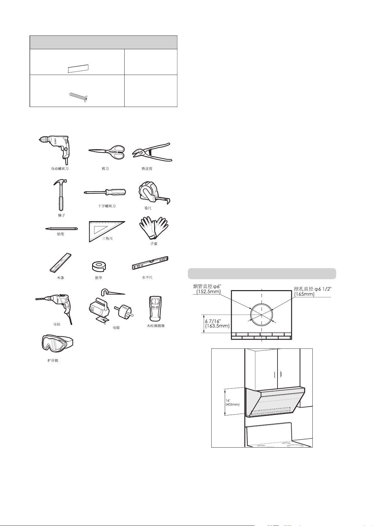
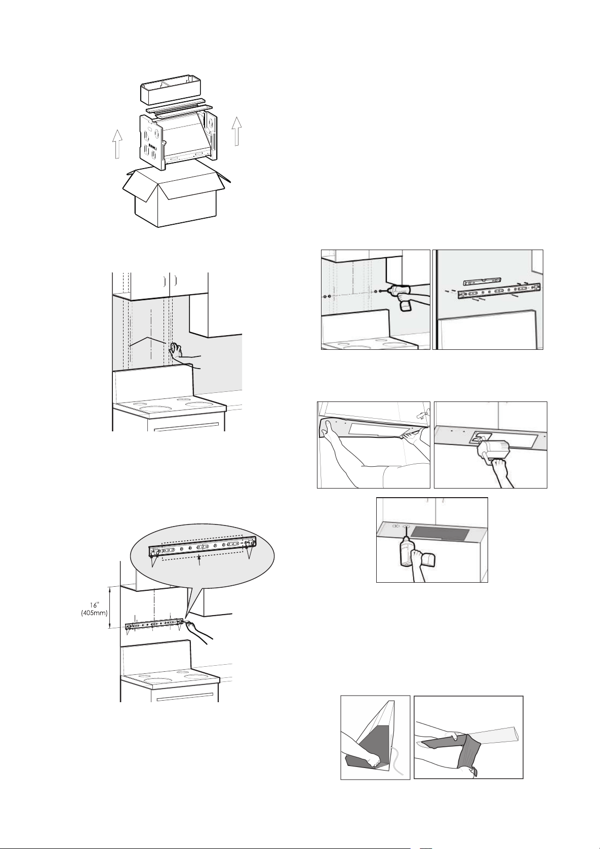
- 12 - - 13 -
4. 固定挂钩:
1)打孔标识处是瓷砖(大理石):在打孔标识
处用电钻打 φ3/8"(φ8mm) 孔,并埋设瓷砖膨
胀管 (φ1/4"×1 5/16"(φ5.3×32mm)),用挂挂
钩 螺 钉 (#8×1 7/16"(ST4.2×36mm)) 固 定 挂
钩,并用水平尺确保挂钩水平。
2)打孔标识处是灰板:在打孔标识处
直接用螺丝刀将灰板膨胀管(φ3/16"×1
5/8"(φ4×40mm)) 拧进墙面,然后用挂钩螺钉
(#8×1 7/16"(ST4.2×36mm)) 固定挂钩,并用
水平尺确保挂钩水平。
5. 把开孔尺寸纸有开孔尺寸图的一面朝下贴在上
柜板底部,然后按开孔纸上要求开孔。
注意:开孔要带上防护眼镜。
如遇底板靠墙一侧有木条,开孔纸 Rear Wall 侧
按此木条厚度裁剪。
如遇挂钩固定在瓷砖上,开孔纸 Rear Wall 一侧
应以瓷砖面为基准贴在上橱柜的底部。
6. 把整机两侧不锈钢表面和油杯保护膜撕掉。
1. 打开包装箱拿出主机,清点附件清单。
2. 在安装位置找到固定挂钩的木柱并用铅笔做好
标记。
木柱
3. 确认固定主机挂钩的位置:首先确认油烟机安
装中心点画一条垂直的中心线,然后以上柜板底
部最低点为基准确认挂钩安装位置,做好打孔标
志。尺寸为:上柜板底部最低点到挂钩孔中心距
16"(405mm)
孔A
区域C
孔B
孔A
区域C
孔B
注 意: 主机挂钩必须有一个木螺钉(#10×2
9/16"(ST5×65mm)) 要固定在木柱上。
图上孔 A、 孔 B必须固定螺钉,区域C 挂钩
孔位能对应木柱部分必须固定木螺钉 (#10×2
9/16"(ST5×65mm))。
10. 整机必须保持水平,再把油杯安装上去并插上
电源试机。
警告:请戴防护手套操作。
注意:铝箔胶带密封后,请开机测试烟管是否有漏
风。烟管尽量能够拉直。
7. 抬起主机倾斜着将背底部挂钩孔挂上挂钩,再
将烟机推上去靠紧墙壁。
注 意:为了安全你需要两个人来安装这个油烟机。
8. 用 3 颗 #10×2 13/16"(M5×70mm) 上柜板固
定螺钉和 3 个 φ1 5/16"(φ32mm) 上柜板固定螺
钉垫圈固定主机,至少固定两颗螺钉后才能松手。
油烟机壳体
上柜
底板
如上柜底板与油烟机壳体之间有较大间隙,安装
前,请在 3 颗 #10×2 13/16"(M5×70mm) 螺钉
附近依据间隙大小加垫木块,以免螺钉紧固时使
油烟机壳体发生变形而影响使用。
油烟机壳体
木板
上柜
底板
9. 在主机出风口放好密封垫(缺口朝下),用 4
颗 #8×3/4"(M4×18mm) 出风罩螺钉固定好出
风罩。再把烟管固定在出风罩上用铝箔胶带做好
密封。
有上柜加装饰板
注 意: 请先确认上柜高度,如果超过 32 1/2"
(825mm), 则 参 考 选 配 6"(152.4mm) 或
4"(101.6mm) 装饰板。
7 11/16"(194.4mm)
or
5 11/16"(143.6mm)
6"(152.4mm)
or
4"(101.6mm)
1. 打开包装箱拿出主机,清点附件清单。
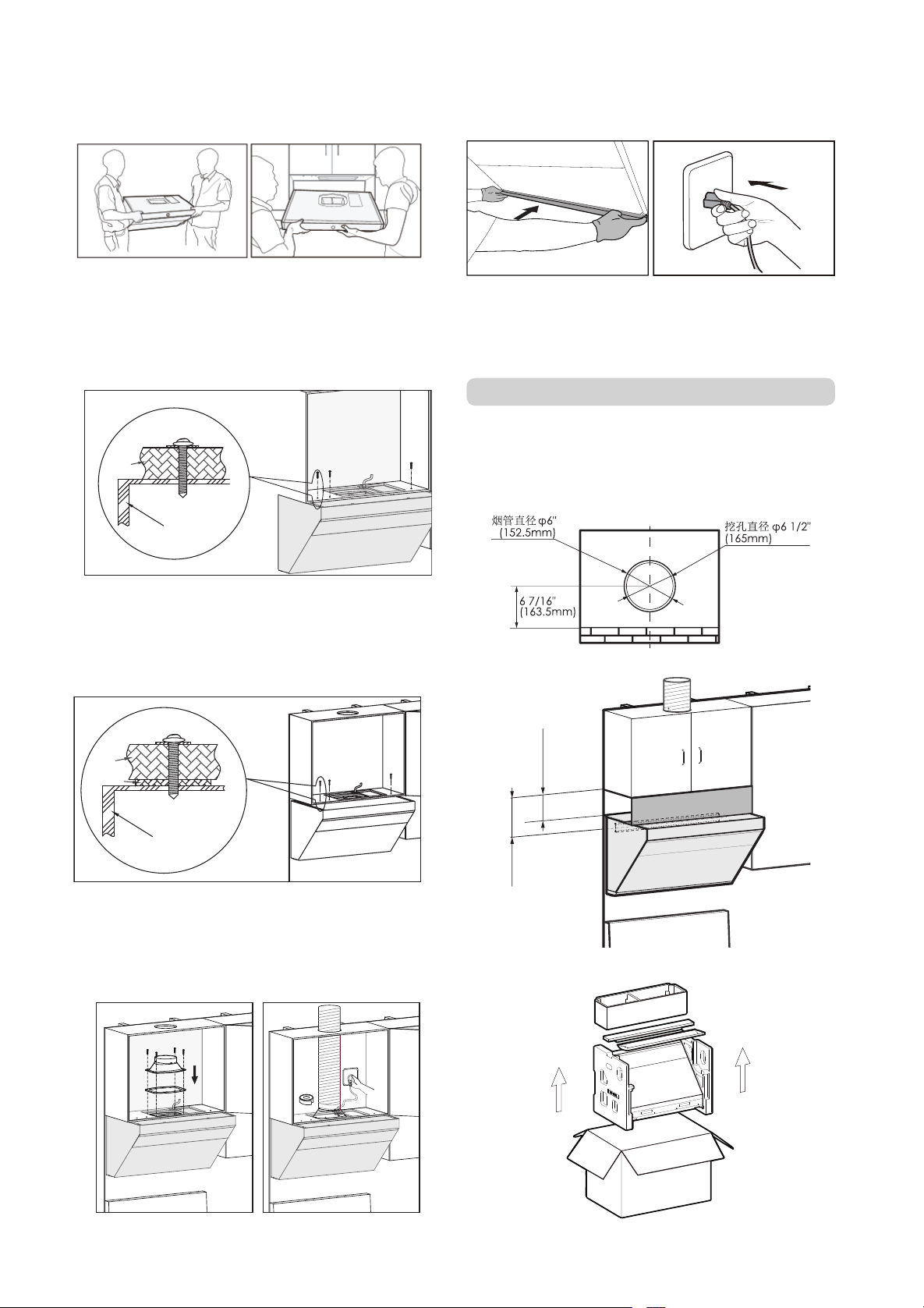
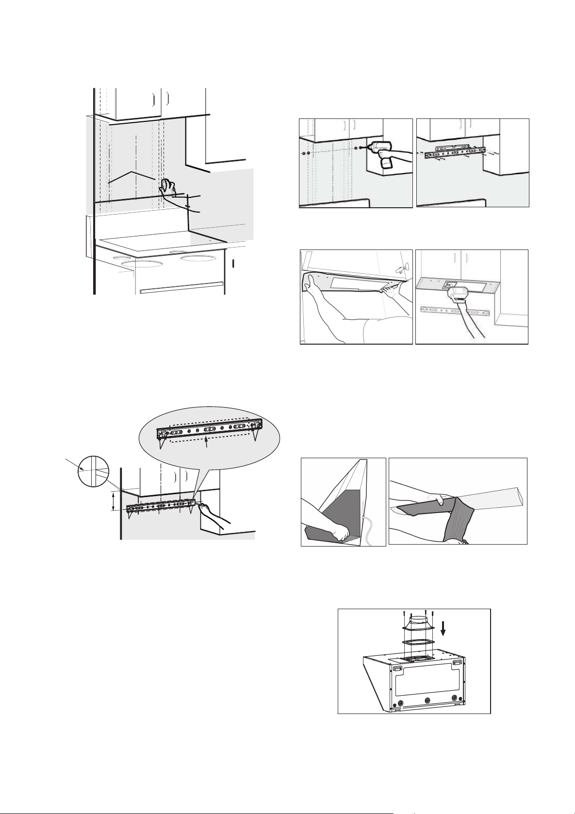
- 14 - - 15 -
2. 在安装位置找到固定挂钩的木柱并用铅笔做好
标记。
木柱
3. 确认固定主机挂钩的位置:首先确认油烟机安
装中心点画一条垂直的中心线,然后以上柜板为
基准确认挂钩安装位置,做好打孔标志。尺寸为:
上柜底板上檐(装饰板与上柜板固定面)为定位
基准到挂钩孔中心点距离为 6" 装饰板 7 11/16"
(194.4mm),4" 装饰板 5 11/16"(143.6mm)
5 11/16"
(143.6mm)
or
7 11/16"
(194.4mm)
孔A
区域C
孔B
孔A
区域C 孔B
上柜底板上檐(装饰板与上
柜板固定面)为定位基准
注 意: 主机挂钩必须有一个木螺钉(#10×2
9/16"(ST5×65mm)) 要固定在木柱上。
图上孔 A、 孔 B 必须固定螺钉,区域C 挂钩
孔位能对应木柱部分必须固定木螺钉 (#10×2
9/16"(ST5×65mm))。
4. 固定挂钩:
1)打孔标识处是瓷砖(大理石):在打孔标识
处用电钻打 φ3/8"(φ8mm) 孔,并埋设瓷砖膨
胀管 (φ1/4"×1 5/16"(φ5.3×32mm)),用挂钩
螺钉 (#8×1 7/16"(ST4.2×36mm)) 固定挂钩,
并用水平尺确保挂钩水平。
2)打孔标识处是灰板:在打孔标识处
10. 整机必须保持水平,再把油杯安装上去并插上
电源试机。
警告:请戴防护手套操作。
注意:铝箔胶带密封后,请开机测试烟管是否有漏
风。烟管尽量能够拉直。
8. 抬起主机将背上部挂钩孔挂上挂钩,再把烟管
固定在出风罩上用铝箔胶带做好密封。
注 意:为了安全你需要两个人来安装这个油烟机。
9. 安装装饰板
用 4 颗 #6×1 7/16"(ST3.5×35mm) 木螺钉固
定装饰板,把装饰板固定在上柜板上 ( 木螺钉在
装饰板包装箱中的附件包内 )。
直接用螺丝刀将灰板膨胀管(φ3/16"×1
5/8"(φ4×40mm)) 拧进墙面,然后用挂钩螺钉
(#8×1 7/16"(ST4.2×36mm)) 固定挂钩,并用
水平尺确保挂钩水平。
5. 把开孔尺寸纸有开孔尺寸图的一面朝下贴在上
柜板底部,然后按开孔纸上要求开孔。
注意:开孔要带上防护眼镜。
如遇底板靠墙一侧有木条,开孔纸 Rear Wall 侧
按此木条厚度裁剪。
如遇挂钩固定在瓷砖上,开孔纸 Rear Wall 一侧
应以瓷砖面为基准贴在上橱柜的底部。
6. 把整机两侧不锈钢表面和油杯保护膜撕掉。
7. 在主机出风口放好密封垫(缺口朝下),用 4
颗 #8×3/4"(M4×18mm) 出风罩螺钉固定好出
风罩。
无上柜加装饰罩
1. 打开包装箱拿出主机,清点附件清单。
2. 在安装位置找到固定挂钩的木柱并用铅笔做好
标记。
木柱
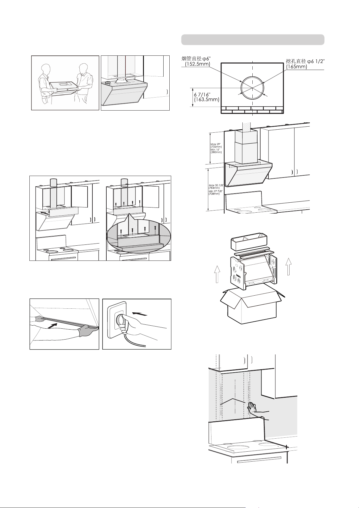
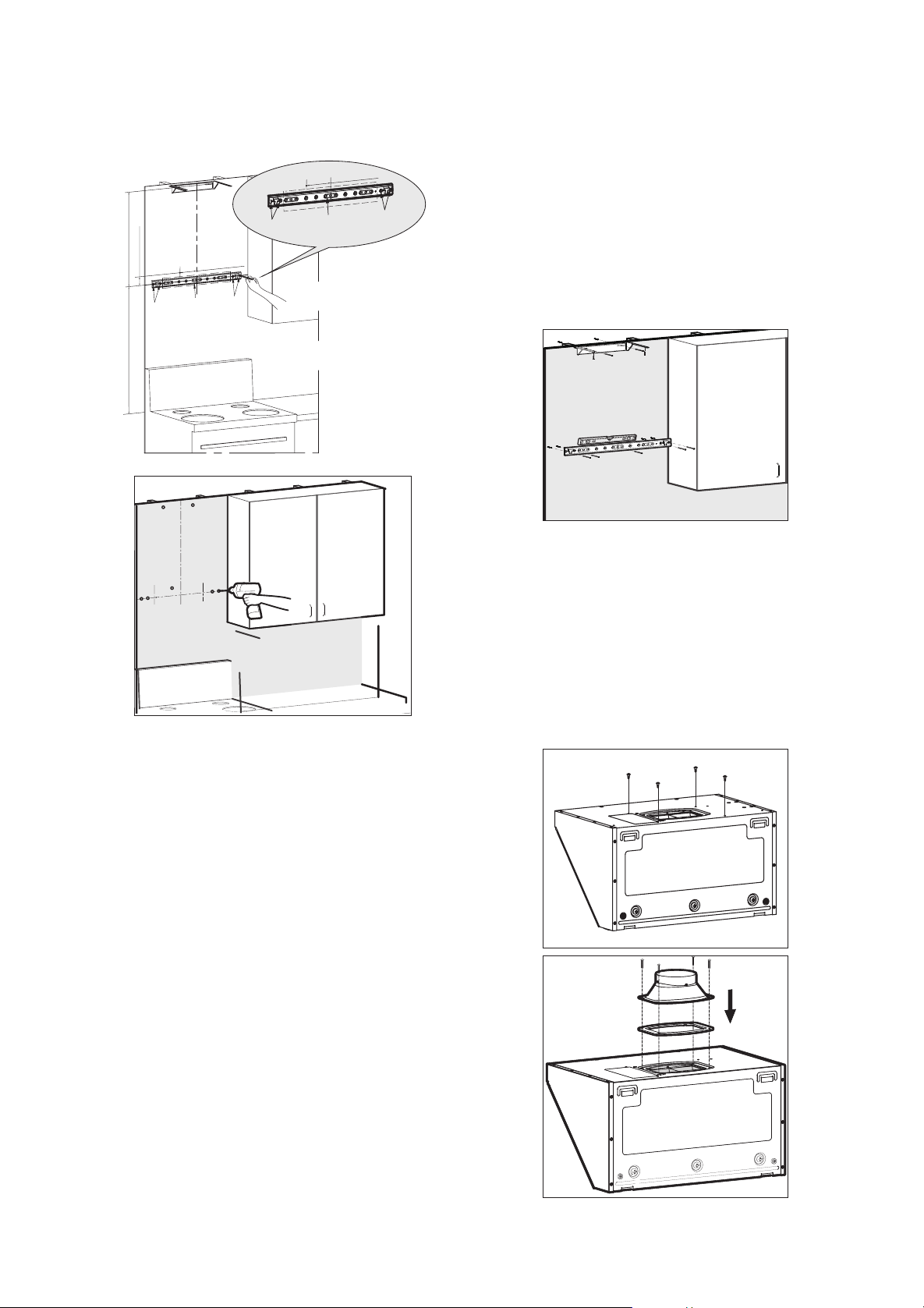
- 16 - - 17 -
3. 确认固定主机挂钩、安全挡块和装饰罩挂钩的
位置:
安全挡块安装孔
2
5
/1
6
"(
5
8
.5
m
m
)
4
9
/1
6
"(
11
5
.5
m
m
)
Max 29 15/16"(760mm)
Max 30 7/8"(783mm)
Min 27 7/8"(708mm)
孔A
区域C
孔B
4
9/16"(115.5mm)
孔A
区域C
孔B
注 意: 主机挂钩必须有一个木螺钉(#10×2
9/16"(ST5×65mm))要固定在木柱上。
图上孔 A、 孔 B必须固定螺钉,区域C 挂钩
孔位能对应木柱部分必须固定木螺钉(#10×2
9/16"(ST5×65mm))。
首先以灶具中心点确认油烟机安装中心点,然后以
灶具台面为基准确认挂钩安装位置,做好打孔标
志。尺寸为:灶具台面到挂钩中心点最低 27 7/8"
(708mm)—30 7/8"(783mm);
安全挡块:挂钩中心线往左 4 9/16"(115.5mm) 再
往上 2 5/16"(58.5mm)
装饰罩挂钩:常规尺寸是,主机挂钩中心点往上
最高 29 15/16"(760mm),如果楼层高度在这个
尺寸内就把装饰罩挂钩与天花板平齐。如楼层高
度高于这个尺寸,那要单独购买加长装饰罩。加
长装饰罩高度有两种分别是:27 9/16"(700mm)
和 35 7/16" (900mm)
打孔标识处埋设膨胀管:
6. 把整机两侧不锈钢表面和油杯保护膜撕掉。
7. 抬起主机将背部上端的挂钩孔挂上挂钩,将油
烟机挂稳并用水平尺确保水平,再把安全挡块固
定在油烟机上方(安全挡块在装饰罩组件包装箱
中的附件包内)。
注 意:为了安全你需要两个人来安装这个油烟机。
请按要求安装安全挡块。安全挡块主要作用为,
防止油烟机被意外上抬导致脱出挂钩,造成掉落
风险。
8. 把烟管固定在出风罩上并用铝箔胶带做好密封。
确保整机水平并插上电源插头。
注意:铝箔胶带密封后,请开机测试烟管是否有
漏风。烟管尽量能够拉直。
9. 首先撕掉装饰罩、风机外罩上的保护膜,把装
饰罩放入风机外罩里。然后同时拿起装饰罩和风
机外罩,将装饰罩挂在装饰罩挂钩上,将风机外
罩慢慢放下,同时推将装饰罩和风机外罩往里推,
直到风机外罩扣到相应的外罩螺钉上。
1)打孔标识处是瓷砖(大理石):在打孔标识
处用电钻打 φ3/8"(φ8mm) 孔,并埋设瓷砖膨
胀管 (φ1/4"×1 5/16"(φ5.3×32mm))。
2)打孔标识处是灰板:在打孔标识处
直接用螺丝刀将灰板膨胀管(φ3/16"×1
5/8"(φ4×40mm)) 拧进墙面。
4. 用相应的螺钉在墙上固定好主机挂钩和装饰罩
挂钩并拧紧螺钉,确认挂钩水平。
注 意: 主机挂钩必须有一个木螺钉(#10×2
9/16"(ST5×65mm)) 要固定在木柱上。
5. 在主机出风口放好密封垫(缺口朝下),用 4
颗 #8×3/4"(M4×18mm) 出风罩螺钉固定好出风
罩。相应位置固定 4 颗 #8×7/16"(M4×10mm)
外罩螺钉 ( 外罩螺钉在装饰罩包装箱内的附件包
中 )。
10. 安装上油杯。
警告:请戴防护手套操作
六、安装后调试:
1. 轻触电源键,再轻触灯键,检查“隔烟屏”是
否正常打开,检查照明灯是否正常;
2. 轻触风量键,检测电机转动是否正常,如出现
下列异常情况,应立即切断电源,停止运转,并
检查是否安装缘故(若确定油烟机发生故障,请
尽快与本公司当地授权的服务中心联系);
(1) 机体震动剧烈
(2) 叶轮不转动
(3) 叶轮转动时明显的摩擦声
(4) 电机出现异常声响
3. 轻触电源开关,风机停止转动,隔烟屏关闭。
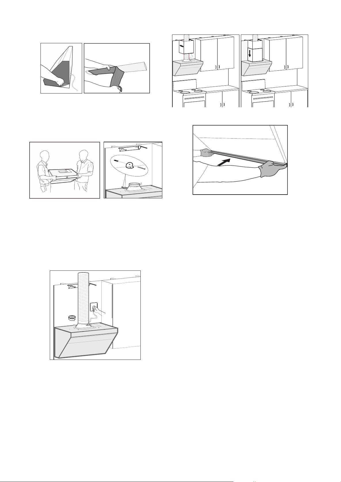
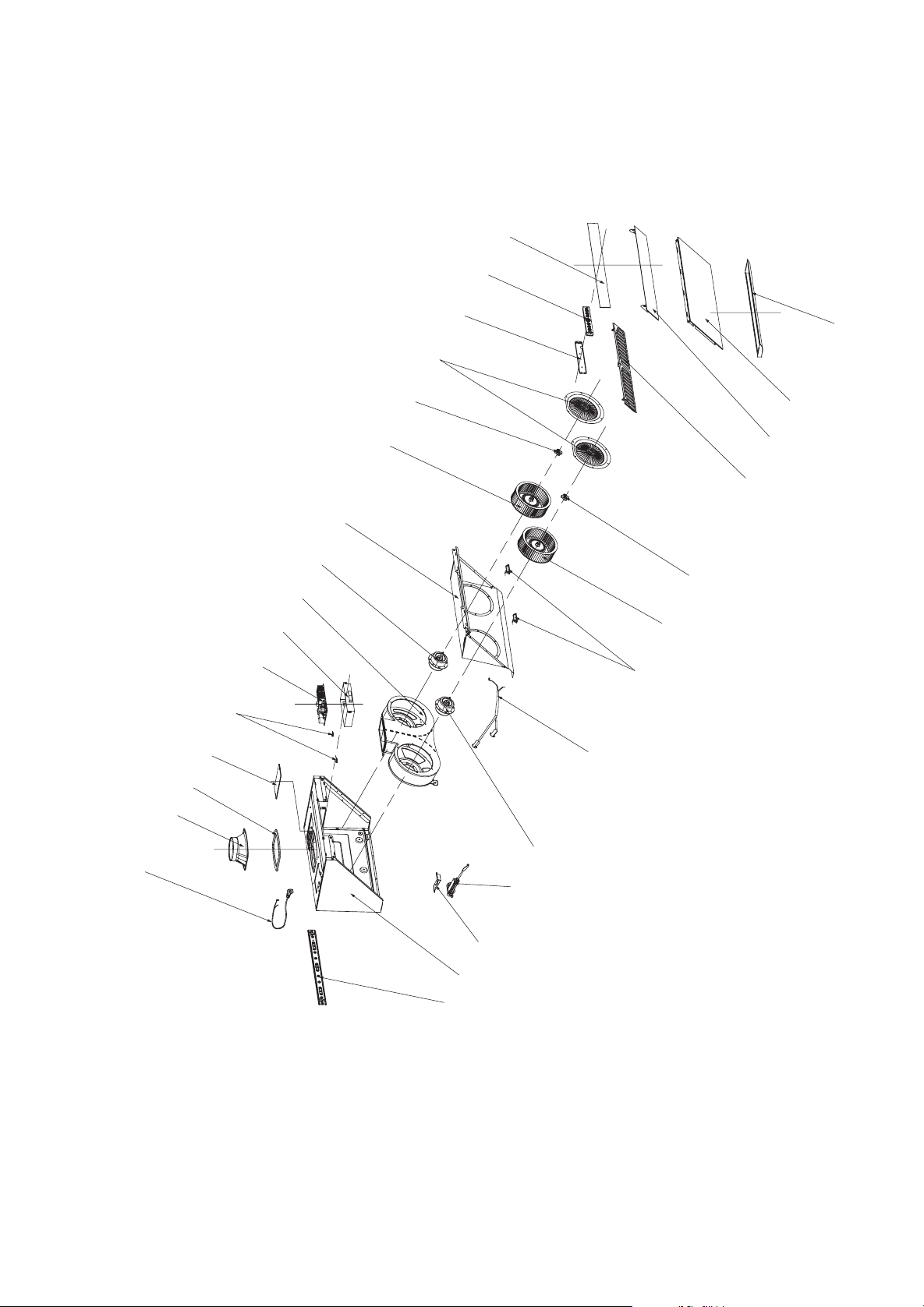
- 18 - - 19 -
爆炸图
JQG7505/JQG7505-W
JQG9006/JQG9006-W
电源线
出风罩
上密封垫
电气盒盖
电气盒支撑块
电源板
电气盒
蜗壳
右电机
导油板
右叶轮
右手紧螺母
进风口圈
控制压板
控制板组件
上玻璃
油杯
下玻璃
挡烟板玻璃
油网
左手紧螺母
左叶轮
LED灯
连接线组件
左电机
电动推杆
推杆支架
箱体
挂钩
电源线
推杆盖
出风罩
上密封垫
电气盒盖
电气盒支撑块
电源板
电气盒
蜗壳
右电机
导油板
右叶轮
右手紧螺母
进风口圈
控制压板
控制板组件
上玻璃
油杯
下玻璃
挡烟板玻璃
右油网
左油网
左手紧螺母
左叶轮
LED灯
连接线组件
左电机
电动推杆
推杆支架
箱体
挂钩
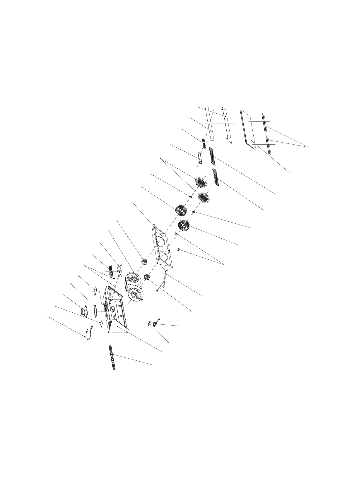

JQG7505/JQG7505-W/JQG9006/JQG9006-W

JQG7505/JQG7505-W/JQG9006/JQG9006-W

- 49 -
Merci !
Cher utilisateur, merci d’avoir choisi ce produit
FOTILE créé spécialement pour vous. Pour vous
familiariser avec toutes les indications concernant la
sécurité, le fonctionnement et l’entretien de la hotte,
veuillez lire attentivement la présente la présente «
Notice d’utilisation et d’installation » (dénommée ci-
après la Notice) avant l’utilisation de l’appareil.
Avant l’utilisation de l’appareil, il est primordial
que vous lisiez attentivement et suiviez les
instructions de la Notice. Les instructions de la notice
sont très importantes pour le bon fonctionnement
du produit. En cas de dommage lié à une utilisation
incorrecte, la garantie ne s’applique pas et aucune
demande directe ou indirecte de garantie gratuite ne
sera acceptée par nos services après-vente. En cas
de besoin de réparations, nous vous recommandons
de contacter notre Service après-vente agréé,
pendant et après la période de garantie du produit.
Pour vous permettre de profiter d’un service
compétent et attentif, notre Service après-vente
vous fournira les pièces de rechange et le soutien
technique professionnel de Fotile de sorte que votre
appareil bénécie d’une maintenance efcace et de
qualité.
Le modèle de produit et le numéro de série
sur la plaque sont requis si vous avez besoin de
services. La position de la plaque peut se voir dans
la figure A comme suit :(Le schéma suivant est le
schéma de modèle de base(JQG7505), veuillez vous
reporter au schéma du modèle de base pour les
modèles dérivés)
(Emplacement de la plaque d’identication)
Sommaire
1 Consignes de sécurité ........................... 50
2 Fonctionnement .................................... 54
3 Nettoyage et entretient .......................... 56
4 Questions fréquentes ............................ 59
5 Service après-vente .............................. 59
6 Installation ............................................. 60
6.1 Instructions d’installation .................. 60
6.2 Dimensions du produit ...................... 61
6.3 Liste des accessoires ....................... 62
6.4
Liste des produits dans l’emballage
..... 63
6.5 Procédure d’installation .................... 63
6.6 Test après l’installation ..................... 71
Pour une utilisation sûre et optimale du produit,
veuillez prêter une attention particulière aux
instructions suivantes dans la présente notice :
NOTE :
pour indiquer les informations très
importantes.
ATTENTION :
le non-respect de ces instructions peut
provoquer des blessures légères ou des dommages
au produit.
AVERTISSEMENT :
le non-respect de ces consignes
de précaution constitue un danger de blessures
graves ou de mort.
Les caractéristiques et les paramètres du produit
peuvent être modiés à tout moment en l’absence de
notication et peuvent légèrement être différents du
manuel. Vous trouverez les informations mises à jour
sur notre site Internet
.
FOTILE YouTube
FOTILE Sàrl (États-Unis)
FOTILE Magasin phare à Toronto
* Adresse
:
Suite 210, 6 Allée Campus, Suite 210, Parsippany, NJ 07054
* Numéro vert
:
888-315-0366
* Site web
:
us.fotileglobal.com
* Email
:
* Adresse
:
8365 Woodbine Ave
,
Markham, L3R2P4
* Numéro vert
:
844-315-0315
* Site web
:
ca.fotileglobal.com
* Email
:
Service WeChat aux E.-U.
Service WeChat aux E.-U.Compte ofciel
Wechat Canada

- 50 - - 51 -
ATTENTION:
• Lorsque les réglementations locales
applicables comprennent les exigences
d’installations et/ou de certification plus
restrictives, lesdites exigences prévalent sur
celles de ce document et l’installateur entend
s’y conformer.
• La température ambiante pour l’utilisation de
la hotte ne doit pas dépasser 104
℉
(40
℃
).
• Les objets déposés sur l’appareil pourraient
tomber ou se renverser. Ne déposez jamais
d’objets sur l’appareil. Si, par exemple, un
flacon déposé sur l'appareil se renversait, le
fluide dans le flacon pourrait s'infiltrer dans
l'appareil, endommager ainsi les pièces
électriques et entraîner des risques évitables.
Si l'appareil était ainsi détérioré, la réparation
ne serait pas prise en charge grauitement.•
Veuillez nettoyer régulièrement la coupe
d’huile pour éviter tout débordement. L’huile
collectée dans la coupe n’est pas réutilisable !
•
Lorsque vous coupez ou percez un mur ou un
plafond, faites attention à ne pas endommager
le câblage électrique, les conduites d’eau ou de
gaz et d’autres équipements cachés. Veuillez
ne pas placer des matériaux inflammables
dans la tasse d'huile, tels que la pellicule
plastique, des serviettes en papier, etc.
• Veuillez suivre les consignes du fabricant de
l’équipement de chauffage et d’autres normes
de sécurité, telles que celles publiées par la
National Fire Protection Association (NFPA),
l’American Society for Heating, Refrigeration
and Air Conditioning Engineers (ASHRAE) et
les autorités désignées par les réglementations
locales. Veuillez respecter également les
normes de sécurité publiées par les services
administratifs comme le service des incendies.
• Lorsque les tables de cuisson à gaz sont en
fonctionnement sans ustensile de cuisson
posé sur elles, l’appareil installé au-dessus
peut être endommagé par la chaleur ou
prendre feu. Sur les foyers gaz, posez toujours
des ustensiles de cuisson lorsque vous les
utilisez.
• Assurez-vous que la tension réelle et la
fréquence sont accordées avec celles
clarifiées dans la notice afin d’éviter les
éventuelles dommages à la hotte.
• Veuillez utiliser les accessoires standards
fournis par notre entreprise, pour éviter
des chutes accidentelles de la hotte ; Les
trous percés sur la paroi du mur doivent
correspondre précisément à la taille des joints
de dilatation, an d’éviter l’instabilité des joints
qui peut provoquer une chute accidentelle.
• Le verre trempé est appliqué à l'appareil. Il
existe ainsi un risque minime d'explosion
spontanée vu le processus de trempe du
verre. Si l'utlisation appropriée de l'appareil
donne lieu à une explosion spontanée, la
société s'engage à remplacer gratuitement la
pièce en question. La possibilité de la rupture
du verre trempé peut être considérablement
augmentée dans les situations ci-après ;
celles à éviter : Par exemple, frapper le verre,
en particulier les coins du verre, avec des
ustensiles de cuisine ou d’autres objets durs;
La vitre est heurtée lorsque vous ouvrez une
porte d'armoire autour de la hotte; Placez le
verre dans un environnement extrêmement
chaud ou froid ou dans un environnement où
la chaleur et le froid alternent excessivement.
• Toute modication non autorisée de ce produit
peut entraîner des risques.
AVERTISSEMENT :
Danger d’électrocution
• Un produit défectueux peut provoquer de
l’électrocution. Ne démarrez jamais un produit
défectueux. En cas de problème, veuillez
débrancher cet appareil de la source de
courant ou couper la source d’alimentation
générale et veuillez contacter les centres de
service agréés de FOTILE.
• L’appareil doit être branché sur une prise
de courant de mise à la terre efficace et
dédiée. L’électrocution, l’échauffement des
prises et l’incendie peuvent survenir lors
de la connexion de ligne d’alimentation
électrique, de l’utilisation de rallonge et de
dispositif de câblage multiport, les opérations
doivent donc toujours être effectuées par
un électricien qualifié, en stricte conformité
In order to prevent accidental damage to the Fotile
Range Hood and/or bodily injuries as a result of
its operation, please read the following safety
informationinstalling and/or using this appliance.
Following the instructions carefully will significantly
reduce the risk of fire, electric shock and/or bodily
injuries to persons. We recommend that you keep
this manual for future use and/or in case of transfer
of ownership of the range hood.
NOTE :
• Le produit ne peut être utilisé qu’à l’intérieur
et non à l’extérieur. Veuillez utiliser le produit
uniquement conformément aux instructions du
fabricant. Si vous utilisez le produit à l’extérieur
ou en des occasions spéciales, Fotile n’en
assumera aucune responsabilité. Si vous avez
des questions, veuillez contacter le centre de
service d’assistance homologué de Fotile.
• Avant d’utiliser ce produit, déballez l’appareil
et assurez-vous de l’absence de dommage.
En cas d’anomalie, n’utilisez pas l’appareil et
contactez immédiatement le centre de service
agréé de FOTILE .
• Garder la hotte loin des matériaux comme
la poudre de plâtre et la poussière de
construction.
• Veuillez utiliser le produit en suivant les
instructions de la notice. Veuillez ne pas faire
fonctionner le produit sans surveillance. En
cas de doute, contactez le centre de service
agréé de FOTILE. .
• En tant qu’utilisateur, vous êtes responsable
du nettoyage, de l’entretien et de l’utilisation
appropriée de la hotte dans votre foyer.
• Veuillez nettoyer le filtre métallique à grasse
selon les conditions réelles.
• Le moteur de la hotte possède une protection
thermique qui coupe automatique le moteur
en cas de surchauffe. Le moteur redémarre
quand il se refroidit. Si le moteur s’éteint et
redémarre constamment, contactez le centre
de service agrée de FOTILE.
• Débranchez l’appareil de la prise en cas
d’inutilisation prolongée.
• Assurez-vous de l’installation et de la
maintenance correctes du produit. L’installation
du produit doit respecter tous les codes et
normes applicables, y compris les normes de
sécurité incendie. L’appareil doit être installé
correctement par un technicien qualifié et
réglementairement relié à la terre. L’installeur
doit s’assurer du fonctionnement normal de
l’appareil en position de montage.
• Lorsque la hotte est en mode d’échappement,
assurez-vous que le clapet anti-retour est
installé.
• Cet appareil est destiné à une utilisation
générale et ne peut pas être utilisé pour
évacuer des matériaux/gaz dangereux et
explosif.
• Le produit est une substance inammable.
• Pour réduire le risque d’incendie, tous
les tuyaux d’échappement, conduits et
composants de l’appareil doivent être non-
inammables. Utilisez uniquement les conduits
en métal. Ne couvrez jamais la hotte avec du
plastique ou du papier inammable.
• Le service de garantie doit être assure par un
service de regulation ou un personnel reconnu
par Fotile. Si vous démontez la machine pour
réparation sans permission, le produit ne sera
plus couvert par la garantie.
• Veuillez lire l’étiquette de spécification sur
la hotte pour plus de renseignements et
exigences.
• Veuillez installer un appareil d’air
supplémentaire si vous installez la hotte de
cuisinière à haute puissance dans une pièce
hermétique. En raison de la configuration de
la hotte Fotile, il est recommandé d'installer
un appareil d’air supplémentaire dans une
nouvelle maison hermétique. Veuillez vous
conformer aux réglementations en vigueur
pour installer un appareil d’air supplémentaire
correspondant si des réglementations
pertinentes existent dans votre état ou votre
région.
• Ce produit est limité aux usa et au Canada.
• L'utilisation de ce produit est réservée aux
États-Unis et au Canada.
Consignes de sécurité

- 52 - - 53 -
2) Mettez toujours la hotte lors des cuissons.
3) Nettoyez la hotte. La graisse ne doit pas
s’accumuler sur le ventilateur, le ltre ou dans
le conduit d’échappement.
4) Utilisez les ustensiles de cuisson aux
dimensions adéquates. Utilisez toujours des
ustensiles adaptés à la talle de surface de la
table de cuisson.
Pour réduire le risque de blessures en cas
de feux de graisse au dessus de la table de
cuisson, respectez les consignes suivantes :
1) Etouffez les flammes avec un couvercle
hermétique, une plaque à biscuits ou un
plateau métallique, puis éteignez la table
de cuisson. Soyez prudent pour éviter les
brûlures. Si les ammes ne sont pas étouffées
immédiatement, évacuez le lieu et appelez le
service d’incendie.
Lorsqu’un ustensile de cuisine prend feu,
éteignez la hotte immédiatement (l’utilisation
de la hotte peut amplier le feu). Des mesures
d’extinction efficaces doivent être prises,
par exemple, couvrir la flamme nue avec
un couvercle en métal, fermer le robinet
de gaz principal et éloigner les substances
inammables de la amme.
2) Ne touchez jamais un ustensile en feu, vous
pouvez vous brûler.
3) N’éteignez jamais le feu avec de l’eau, ni avec
les torchons ou les serviettes humides. Une
violente explosion de vapeur peut se produire.
4) Utilisez un extincteur seulement si :
-Vous avez suivi des formations de base sur
l’extincteur et vous maîtrisez déjà l’utilisation
de celui-ci ;
-Le feu est petit et restreint dans la zone où il a
commencé ;
-Le service d’incendie est appelé ;
-Vous pouvez combattre le feu avec votre dos
à une sortie.
Risque de blessures
• Cet appareil n’est pas destiné à être utilisé par
des personnes (y-compris des enfants) dont les
capacités physiques, sensorielles ou mentales
sont réduites, ou manquant d’expérience et
de connaissances, à moins qu’elles ne soient
surveillées ou instruites par une personne
responsable de leur sécurité sur le mode
l’utilisation de l’appareil. Surveillez les enfants
et faites en sorte qu’ils ne jouent pas avec
l’appareil.
• Les arêtes de la hotte peuvent être très
vives : veuillez toujours porter des gants de
protection lorsque vous manipulez l’appareil
et particulièrement lorsque vous l’installez, le
nettoyez et le réparez, pour éviter les blessures
causées par les bords métallique de l’appareil.
• Les parties accessibles de l’appareil deviennent
très chauds lors de fonctionnement. Ne touchez
jamais les parties chaudes. Veillez à maintenir
les enfants à distance de sécurité.
• Ne touchez pas les ampoules allumées ou à
peine éteintes pour éviter les brûlures.
• Pour éviter des blessures, il est interdit de mettre
vos doigts ou tout autre objet dans la turbine de
l’appareil lorsqu’elle est en fonctionnement.
• Cet appareil n’est pas prévu pour fonctionner
avec une minuterie externe ou une
télécommande.
• Des réparations inexpertes sont dangereuses.
Les réparations sont exclusivement réservées à
un technicien qualié du Service après-vente.
• En cas d’anomalie de fonctionnement de
l’appareil, coupez le courant par le disjoncteur
ou débranchez la fiche mâle de la prise de
courant. Contactez immédiatement notre centre
de service agréé. L’utilisation de l’appareil dans
des conditions anormales peut provoquer des
risques d’électrocution et d’incendie.
• Ce produit peut vous exposer à une substance
chimique et l'État de Californie est informé
qu'elle est carcinogène et provoque des
malformations congénitales ou d'autres risques
pour la reproduction. Pour plus d'informations,
veuillez consulter le site : www.P65Warnings.
ca.gov.
Risque d’étouffement
• Le matériau d’emballage est dangereux pour les
enfants. Pour éviter les accidents d’asphyxie,
ne permettez jamais aux enfants de jouer avec
avec tous les codes électriques nationaux
et locaux applicables. Avant le câblage,
couper l’alimentation et prendre des
mesures raisonnables pour éviter l’activation
automatique de l’interrupteur.
• Il est interdit d’utiliser l’appareil avec un
courant alternatif supérieur à 120V an d’éviter
tout danger.
• Il est interdit d’installer le produit dans une
salle de bains ou les endroits très humides
pour éviter l’électrocution.
• Si le câble d’alimentation est endommagé,
il doit être remplacé par le fabricant ou
les professionnels des centres de service
autorisés par le fabricant, afin d’éviter tout
danger.
• Pour éviter les risques d’électrocution et
d’incendie, veillez à ne pas restructurer, étirer,
plier ni presser le câble d’alimentation.
• Les moteurs, les interrupteurs, les connecteurs
et autres composants électriques ne doivent
pas être en contact avec l’eau. Il est interdit
de rincer la hotte avec de l’eau. Ne pas
utiliser l’appareil s’il est humide, l’utilisation
peut provoquer des fuites de courant et
l’électrocution.
• Toute modification non autorisée au câblage
interne du produit est interdite. Toute modication
peut provoquer un dysfonctionnement et des
blessures. Une maintenance inappropriée
peut provoquer des risques d’électrocution et
d’incendies.
• Avant de nettoyer, d’installer ou d’entretenir
l’appareil, coupez le courant afin d’éviter
l’électrocution.
• Ne jamais utiliser de nettoyant à haute pression
ou de nettoyeur à vapeur, qui peut provoquer
l’électrocution.
• Ne jamais toucher les composants électriques
du connecteur ou manipuler l’interrupteur avec
les mains mouillées qui peuvent provoquer
l’électrocution.
Mise à terre
• Pour prévenir tout choc électrique en cas de
court-circuit, l’appareil doit être mis à terre. Ce
produit est dotéd’un l de mise à terre avec che
de terre. La che doit être raccordée à une prise
de terre installée correctement.
• Une utilisation impropre de la che de terre peut
provoquer un choc électrique.
• En cas de doute sur la compréhension des
instructions de la notice ou sur la mise à la terre
du produit, veuillez consulter un électricien
qualié.
• Ne pas utiliser de rallonge. Si le câble
d’alimentation est trop court, demandez à
un électricien qualifié d’installer une prise de
courant à proximité de l’appareil.
Risque d’incendie
• Pour réduire le risque d’incendie, l’air sortant
doit être évacué à l’extérieur. Ne rejeter pas l’air
sortant dans des murs ou des plafonds, ni dans
le grenier, des espaces étroits ou le garage.
• Le non-respect des méthodes de nettoyage
décrites dans la notice peut provoquer des
risques d’incendie.
• L’huile chaude et la graisse peuvent s’enammer
spontanément. Ne faites chauffer de la
graisse ou de l’huile qu’en les surveillant en
permanence.
• Les dépôts de graisse dans le filtre à graisse
peuvent prendre feu, nettoyez régulièrement le
ltre à graisse.
• Ne pas utiliser l’appareil en l’absence du ltre à
graisse.
• Les dépôts de graisse dans le filtre à graisse
peut prendre feu. Ne manipulez jamais de
flamme nue à proximité du produit. Ne pas
installer l’appareil à proximité des foyers à
combustibles solides (p.ex. bois ou charbon). La
projection d’étincelles peut provoquer le risque
d’incendie. Evitez de flamber des mets sous
l’appareil.
Pour réduire le risque de feux de graisse des
foyers :
1) Ne laissez jamais les ustensiles de cuisson
chauffer à feu fort sans surveillance. Les
débordements peuvent provoquer le risque
d’incendie par de la fumée et de l’huile. Faites
chauffer les huiles graduellement à feu doux
ou moyen.
- 54 - - 55 -
(1)Fonction de geste : Un branlement rapide
de la main dans les fenêtres à induction sur
les deux côtés de l’appareil permet d’ouvrir
automatiquement l’écran d’isolation de fumées
et de faire fonctionner la hotte à la marche forte,
l’éclairage est également allumé ; un nouveau
Fonctionnement
1. Bandeau de commande
2. Description
Fonctionnement
AVERTISSEMENTS
1. Ne pas appuyer trop fort sur les touches ;
2. Ne pas laisser les ustensiles chauffer à vide ;
3. Démonter l’appareil seulement après avoir coupé
le courant et respecter les consignes relatives ;
4. Ne pas laisser déborder la coupe d’huile ;
5. Le démontage et la vérication de l’appareil
sont exclusivement réservés au personnel
professionnel ;
6. Il est interdit de laisser les flammes nues
sous la hotte.
Informations du produit
Principales spécications techniques
Modèle JQG7505/JQG7505-W
Dimensions du produit
LxDxH
29 7/8 × 18 7/16 × 17 7/16 pouce
(758 × 467 × 442 mm)
Poids net 63,9 lbs(29Kg)
De tension/Fréquence 120V/60Hz
Puissance nominale
d’entrée de l’appareil
210 W (puissance lumineuse
incluse 3W × 2 )
CFM(HVI)
Marche Max.
600
Marche Fort
540
Marche Moyen
420
Marche Min. 230
Bruit
Marche Max.
56dB(A)(7,2Sones)
Marche Fort
53dB(A)(6,2Sones)
Marche Moyen
48dB(A)(3,9Sones)
Marche Min. 38.5dB(A)(1,2Sones)
Pression statique
maximale
560 Pa
Modèle JQG9006/JQG9006-W
Dimensions du produit
LxDxH
35 7/8 × 18 7/16 × 17 7/16 pouce
(910 × 467 × 442 mm)
Poids net 70.1 lbs(31.8Kg)
De tension/Fréquence 120V/60Hz
Puissance nominale
d’entrée de l’appareil
210 W (puissance lumineuse
incluse 3W × 2 )
Bruit
Marche Max.
56dB(A)
Marche Fort
53dB(A)
Marche Moyen
48dB(A)
Marche Min. 38.5dB(A)
Pression statique
maximale
560Pa
les matériaux d’emballage. Tenez les enfants à
l’écart des matériaux d’emballage. Le matériau
d’emballage n’est pas un jouet.
Danger de mort :
• Des gaz de combustion réaspirés peuvent
provoquer des dangers d’intoxication. Ne
jamais utiliser l'appareil en mode évacuation
en même temps qu'un foyer à air ambiant si un
apport sufsant en air frais n'est pas assuré. Un
conduit spécique (par exemple cheminée) doit
permettre le rejet des gaz de fumé et éviter la ré-
aspiration.
Fenêtre
induite
Verrouillage
de l’écran
Minuterie Eclairage Alimentation Marche
Fort/Max.
Marche
Moyen
Marche
Min.
Fenêtre
induite
Note :
1. Le bruit en dB dans le tableau ci-dessus est
conforme à la norme IEC60704, c'est le niveau
de pression acoustique ; le niveau de puissance
sonore correspondant est : Max. 68dB(A), Fort
65dB(A), Moyen 60dB(A), Min. 52.5dB(A).
2. Le bruit (sones) est conforme aux critères de
HVI-915-2015 et résulte du test réalisé dans un
laboratoire américain de HVI agréé.
3. Il y peut avoir un écart de moins de 10% pour les
paramètres du bruit, etc..
Note :
1. Le bruit en dB dans le tableau ci-dessus est
conforme à la norme IEC60704, c'est le niveau
de pression acoustique ; le niveau de puissance
sonore correspondant est : Max. 68dB(A), Fort
66dB(A), Moyen 60dB(A), Min. 52.5dB(A).
2. Il y peut avoir un écart de moins de 10% pour
les paramètres du bruit, etc..
HVI-2100 CERTIFIED RATINGS comply with
new testing technologies and procedures prescribed
by the Home Ventilating Institute, for off-the-shelf
products, as they are available to consumers.
Product
performance is rated at 0.1 in. static pressure, based
on tests conducted in a state-of-the-art test laboratory.
Sones are a measure of humanly-perceived loudness,
based on laboratory measurements.
branlement rapide permet de désactiver toutes
les fonctions, d’éteindre les voyants et de
refermer l’écran, ainsi s’arrête la hotte.En cas
de désactivation, appuyez simultanément sur
les boutons
《
Illumination
》
et
《
Vitesse
moyenne
》
pendant 5 secondes pour activer/
désactiver la fonction de détection de geste.
(2)Touche d’alimentation : Après avoir touché
légèrement lors de l’arrêt, la hotte se met en
mode de veille, la touche d’alimentation
s’allume entièrement et les autres voyants la
moitié : un léger contact de cette touche lors de
son fonctionnement conduit à la désactivation de
toutes les fonctions, l’éteinte du rétroéclairage de
la touche et la fermeture automatique de l’écran
isolation de fumées, ainsi la lotte se trouve en
état demi-arrêt.
À part de la touche de verrouillage de l'écran,
les autres touches ne sont activées qu’après
l’activation de l’alimentation.
(3)Touche Fort/Max. : Après un léger contact,
l’écran d’isolation de fumées est activé
automatiquement avec le démarrage du
ventilateur, le voyant de la marche Fort/Max
s’allume entièrement, la hotte fonctionne à la
marche forte ; l’appui une fois de plus sur cette
même touche permet d’arrêter le fonctionnement
du moteur, son rétroéclairage devient à moitié
allumé ; après avoir appuyé longuement (2s au
moins) sur la touche Fort/Max , son voyant
s’allume entièrement en vert, la hotte fonctionne
à la vitesse maximale,Appuyer de nouveau
longuement (2s au moins) sur la touche Fort/Max
, la hotte retournera à la vitesse maximale, son
voyant s’allumant entièrement ; un nouvel appui
sur cette touche peut arrêter l’appareil, le voyant
de la marche Fort/Max retrouve moitié allumé.
(4)Touche Moyen : Un léger contact conduit à
l’activation automatique de l’écran d’isolation de
fumées, le voyant de la marche Moyen s’allume
en entier et la hotte fonctionne à la vitesse
moyenne ; un nouveau contact de cette touche
permet d’arrêter le moteur et de remettre le
voyant correspondant moitié allumé.
(5)Touche Min. : Un léger contact conduit à
l’activation automatique de l’écran d’isolation de
fumées, le voyant de la marche Min. s’allume
en entier et la hotte fonctionne à la vitesse lente ; un
nouveau contact de cette touche permet d’arrêter
le moteur et de remettre le voyant correspondant
moitié allumé.
(6)Touche de l’éclairage : Un léger contact
conduit à l’activation automatique de l’écran
d’isolation de fumées, l’éclairage est allumé et
le voyant d’éclairage l’est aussi ; un nouveau
contact de cette touche permet d’éteindre la
lumière, son voyant retrouve à moitié allumé.
(7)Touche Minuterie : Un léger contact de la
touche durant le fonctionnement de la hotte
conduit à l’allumage entier du voyant de la touche
Minuterie, la hotte se met en état d’arrêt reporté
de 2 minutes à l’issue desquelles toutes les
fonctions seront désactivées, l’écran d’isolation
de fumées se fermera automatiquement et la
hotte s’arrête.
Lorsque l’appareil se trouve en état de report, un
contact léger de la touche Minuterie permet
de quitter le mode de report, le voyant de report
redevient moitié allumé, la hotte reste en mode
de fonctionnement actuel.
Lorsque l’appareil se trouve en état de report, le
contact d’une touche quelconque sauf celle de
report mène à la sortie du report, et le voyant de
report se rallume à moitié, la fonction de la touche
correspondante est exécutée.
Lorsque la hotte se trouve en état d’arrêt, la
touche de report est invalide, un appui sur cette
touche déclenchera l’alarme.
(8)Touche Verrouillage d’écran : Lorsque la hotte
se trouve en état d’arrêt, l’appui long (au moins
2s) sur la touche de verrouillage permet de
verrouiller toutes les touches après un « bip », ainsi
le voyant de la touche de verrouillage s’allume
entièrement et clignote, toutes les touches sont

- 56 - - 57 -
NOTE :
• Après le nettoyage, veuillez réinstaller
correctement le filtre à grasse. Ne pas faire
fonctionner la hotte en l’absence de filtre
à grasse pour éviter le risque de sécurité
éventuel.
• Le schéma suivant est le schéma de modèle
de base(JQG7505), veuillez vous reporter au
schéma du modèle de base pour les modèles
dérivés.
ATTENTION:
• Risque de détérioration par la corrosion.
Toujours allumer l'appareil pendant la cuisson
an d'éviter la formation de condensation. La
condensation peut provoquer de la corrosion.
• Les surfaces peuvent être endommagées
par un nettoyage non conforme. Nettoyer les
surfaces en inox seulement dans le sens du
métal. Pour les organes de commande, ne
pas utiliser de nettoyant pour inox.
• Les nettoyants agressifs ou à récurer peuvent
endommager la surface.
• Changez immédiatement les LED défectueuses
pour empêcher une surcharge des autres
lampes.
Attention:
Au bout de 2 minutes sans opération
en mode veille, la hotte aspirante s'éteindra
automatiquement.
AVERTISSEMENT:
• Le non-respect des méthodes de nettoyage
indiquées dans les instructions peut
provoquer le risque d’incendie.
• Lorsque vous nettoyez la hotte, faites attention
pour éviter que l’eau pénètre dans le moteur
ou dans les touches de commande. La
présence d’eau dans le circuit électrique peut
endommager l’appareil.
• N’utilisez jamais d’essence, de produits
acides, de benzène, de solvant ou d’autres
produits chimiques pour nettoyer la hotte.
Risque d’électrocution :
• L’humidité pénétrée peut provoquer un choc
électrique. Avant le nettoyage et l’entretient
de la hotte, débranchez l’appareil de la
prise d’alimentation ou coupez l’alimentation
principale pour éviter le risque d’électrocution.
• Ne pas utiliser de nettoyeurs à haute pression
ou à vapeur, qui peuvent provoquer un choc
électrique.
Risque d’incendie :
• Les dépôts de grasse dans le filtre à grasse
peuvent prendre feu.
• Veuillez ne pas placer des matériaux
inammables dans la tasse d'huile, tels que la
pellicule plastique, des serviettes en papier, etc.
• Veuillez éviter une accumulation excessive
d'huile et nettoyez régulièrement la coupelle
d'huile et les autres composants susceptibles
d'accumuler de l'huile.
Risque de blessures :
• Avant toute opération d’installation, de
nettoyage ou de réparation de l’appareil,
assurez-vous que le courant est coupé pour
éviter l’électrocution. Les arêtes de la hotte
peuvent être très vives : veuillez toujours
porter des gants de protection lorsque vous
manipulez l’appareil et particulièrement
lorsque vous l’installez, le nettoyez et le
réparez, pour éviter les blessures causées
par les bords métallique de l’appareil.
Nettoyage et entretient
bloquées et invalides ; une répétition de cette
opération permet de désactiver le verrouillage.
Pendant le fonctionnement de la hotte, la touche
de verrouillage reste invalide, un appui sur
cette touche déclenchera l’alarme.
Invite:
1. En mode veille, aucune opération n'est effectuée
pendant 2 minutes et la hotte aspirante est
automatiquement mise hors tension;
2. Il est recommandé d’allumer la hotte aspirante
pendant la cuisson an de maintenir l'air frais dans
la cuisine, faute de quoi une plus grande quantité
de vapeur d'eau pourrait déclencher la fonction
de geste lors du passage à travers la fenêtre de
détection.
• Lorsque le ventilateur est en cours d’utilisation,
il est interdit de mettre la main dans la zone
de fonctionnement du ventilateur.
• L’appareil, en particulier les parties autour
de lampes LED, chauffe pendant le
fonctionnement. Avant de nettoyer l’appareil,
attendez toujours qu’il ait refroidi. Ne touchez
pas les ampoules LED allumées ou à peine
éteintes, vous risquez de vous brûler.
• Pour un nettoyage en profondeur de la hotte,
contactez un centre de service agréé de FOTILE.
• Pour une utilisation agréable du produit,
veuillez nettoyer régulièrement la surface de
la hotte.
1) Si la surface de la hotte est tâchée, utilisez
un détergent doux pour nettoyer les taches en
évitant les éléments de commande. Mettez du
détergent sur les endroits tâchés, laissez agir
(ne pas laisser le détergent trop longtemps
sur l’appareil pour éviter des dommages) et
essuyez les tâches avec un chiffon doux.
Utilisez une serviette légèrement humide
pour nettoyer le détergent, puis une serviette
douce et sèche pour sécher l’appareil.
2) Ne laissez pas les tâches rester trop
longtemps sur la surface de la hotte.
3) Si de la solution saline, du désinfectant, de
l’eau de javel ou d’autres nettoyants tombe
accidentellement sur le panneau en acier
inoxydable, essuyez immédiatement avec
une serviette légèrement humide, puis séchez
avec un chiffon sec.
AVERTISSEMENTS :
N’utilisez jamais de
produits à récurer tels que les balles de
nettoyage, les brosses et les chiffons abrasifs
pour éviter les rayures sur la surface de
l’appareil.
Préparations avant le nettoyage :
1.Débranchez la prise électrique de la hotte ou
débranchez la prise de courant.
2.Nettoyez les ustensiles sur la plaque de
cuisson .
3.Préparez un détergent doux et un chiffon
doux (brosse douce) .
Détergent doux Chiffon mouillé
Nettoyez la surface de l’appareil, la coupe
d’huile et le ltre à graisse : (Cette opération
peut être effectuée par l’utilisateur)
1. Nettoyez la surface de l’appareil.
2. Enlevez la coupe d’huile d'une manière
horizontale et nettoyez-la.
Avertissement:
Pour votre sécurité et celle
de votre famille, nettoyez régulièrement l'huile
contenue dans le gobelet et déposez les
sédiments sur la surface extérieure du gobelet
afin d'éviter tout risque d'incendie. Veuillez
utiliser des gants de protection.
3. Appuyez sur la touche Marche/Arrêt, puis
appuyez sur la touche Eclairage, ouvrez l’écran
de fumée.
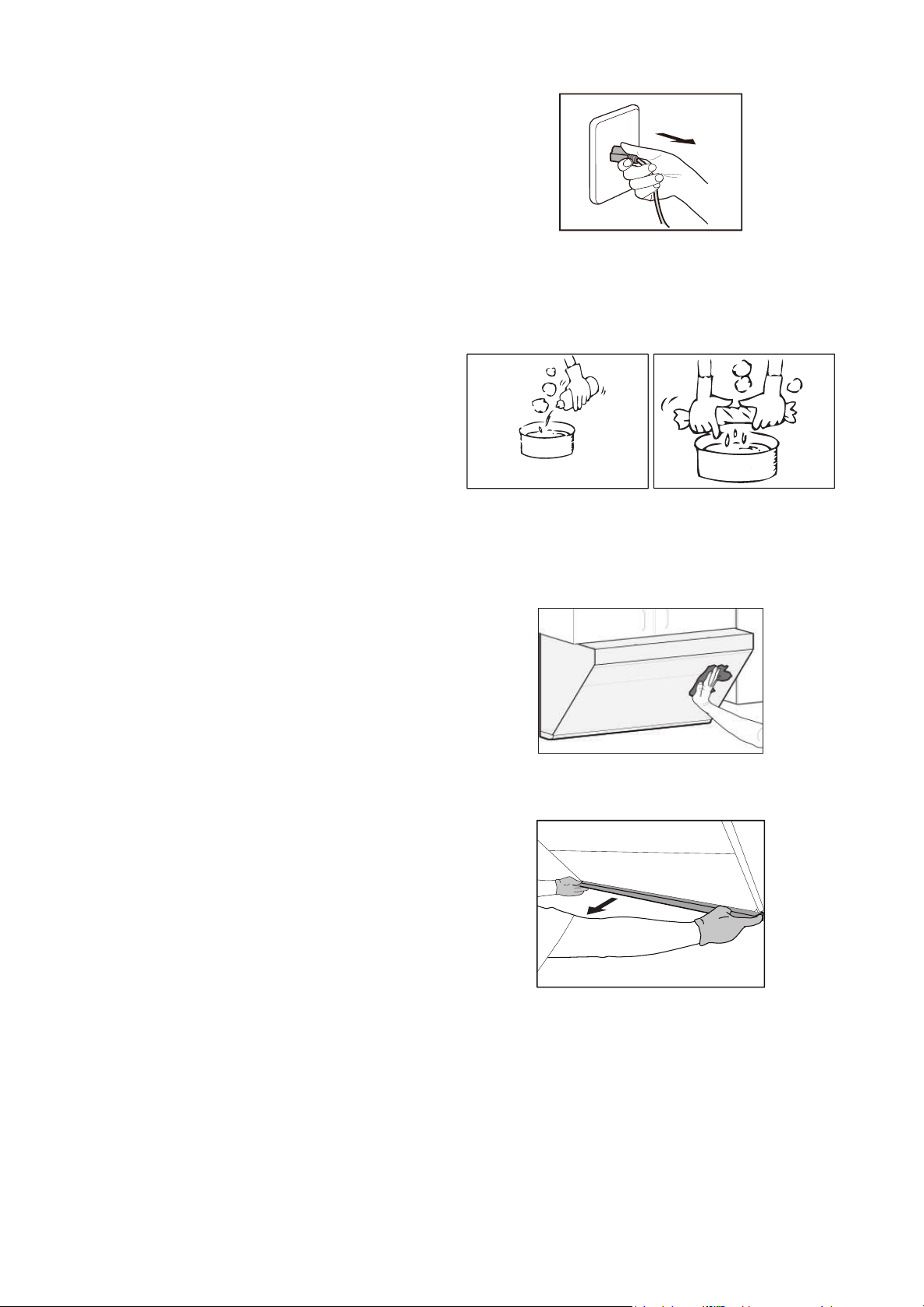
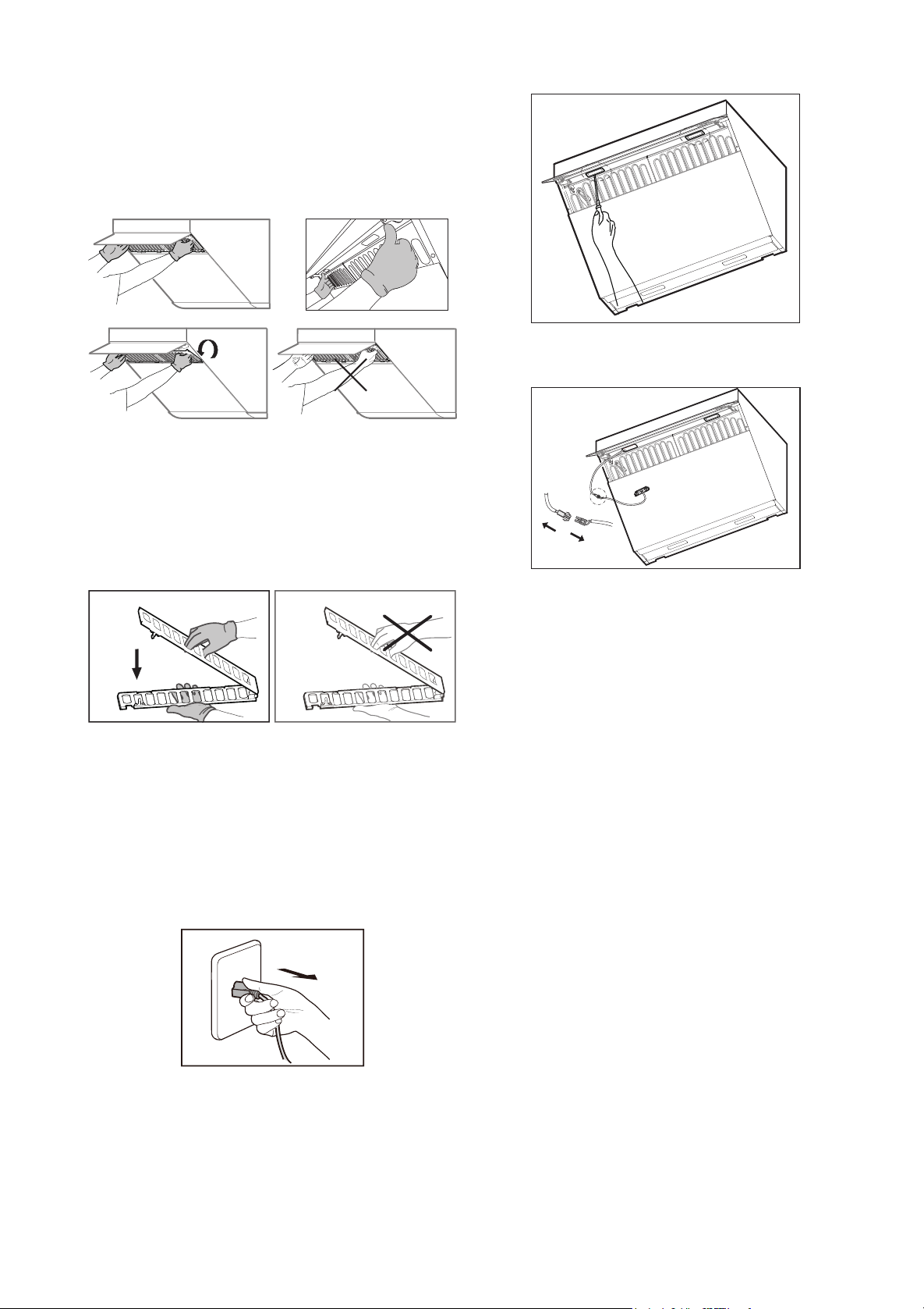
- 58 - - 59 -
4. Empoignez le ltre à graisse de part et autre,
puis sortez le filtre à graisse en le tirant vers
l’extérieur.
Avertissement :
Veillez porter des gants de
protection.
★
RECOMMANDATIONS :
Pour votre santé
et celle de votre famille, nettoyez régulièrement
le filtre à graisse. Le filtre à graisse peut être
nettoyé au lave-vaisselle.
Avertissement:
Veillez porter des gants de
protection.
Changer les LED :
1. Appuyez sur la touche Marche/Arrêt, puis
appuyez sur la touche Eclairage, ouvrez l’écran
de fumée ;
2. Débranchez la prise électrique de la hotte ou
débranchez la prise de courant.
3. Utilisez un petit tournevis plat pour insérer
dans le bord de la lampe et enlevez l’ensemble
de la lampe.
Questions fréquentes
AVERTISSEMENTS : RISQUE D’ELECTROCUTION
• Des réparations inexpertes sont dangereuses.
Les réparations et le remplacement des
câbles d’alimentation endommagés sont
exclusivement réservés à nos centres de
services agréés ou aux électriciens qualiés.
Si l'appareil présente une quelconque
défaillance, débranchez la fiche mâle de la
prise de courant ou coupez le courant de
la prise femelle pour éviter l'électrocution.
Contactez le service après-vente agréé par
FOTILE.
4. Démontez le câble de la lampe et remplacez
toute la lampe LED.
La lampe utilisée est LED: la puissance de la
lampe est de 3 W, la plage de tension est de 8,5 ~
12 V et la taille de la lampe est : largeur 2 13/16"
(70mm) / profondeur 7/8" (21mm)/ hauteur 3/4"
(19mm).
Risque d’électrocution :
Avant le changement de la lampe LED,
débranchez la che mâle de la prise de courant
ou coupez le courant de la prise femelle pour
éviter l'électrocution.
Service après-vente
AVERTISSEMENTS
• Si la hotte aspirante présente une quelconque
anomalie, arrêtez d'utiliser l'appareil.
Débranchez la fiche mâle de la prise de
courant ou coupez le courant de la prise
femelle. Contactez le service après-vente
agréé par FOTILE.
• Avant le changement de la lampe LED,
débranchez la fiche mâle de la prise de
courant ou coupez le courant de la prise
femelle pour éviter l'électrocution.
• Dans le cas d'une quelconque anomalie
pendant l'utilisation, arrêtez d'utiliser l'appareil.
Débranchez la fiche mâle de la prise de
courant ou coupez le courant de la prise
femelle. Examinez les éléments ci-dessous.
Dysfonctionnement Causes possibles
La touche Marche/Arrêt ne
répond pas. La hotte ne
fonctionne pas et l’éclairage
ne s’allume pas.
Pas d’alimentation
électrique.
Le moteur fonctionne mais
l’éclairage ne s’allume pas.
LED défectueuses
Si les causes ci-dessus sont exclues et l’appareil
ne fonctionne toujours pas, contactez le centre
de service agréé par FOTILE pour la réparation.
• Les réparations de l’appareil sont exclusivement
réservées au personnel qualifié ayant suivi
une formation professionnelle.
• D’autres personnels ne sont pas autorisés à
réparer la hotte sans autorisation, an d’éviter
de graves conséquences. Si le produit est
endommagé en conséquence, il ne sera plus
couvert par la garantie.
• Évitez de réparer ou de remplacer une
pièce de la hotte à moins que cela ne soit
spéciquement suggéré dans le manuel. Tous
les autres travaux d'entretien doivent être
effectués par des techniciens qualiés.
• Les éléments suivants ne sont pas couverts
par la garantie gratuite et seront factures pour
des réparations :
1.Le produit est endommagé du fait de la
manipulation, l’installation, l’utilisation,
l’entretien et la conservation impropres par
l’utilisateur.
2.Le défaut ou dommage causés par l’utilisation
forcée du produit sous des conditions de
service anormales (par. ex. le dommage
causé par la tension excédent 132V ou
inférieure à 104V).
3.Produit installé et démonté par un l’utilisation
ou par un personnel de service ou une
organisation de service non désigné par
Fotile.
4.L’incohérence des informations sur le bon
d’achat et sur la carte de garantie avec le
produit.
5.Dommage sur le produit causé par une force
majeure (comme une catastrophe naturelle, la
guerre, etc.).
6.Défaillance ou dommage du produit causé par
la défaillance à utiliser le produit conformément
aux « Instructions d’utilisation ».
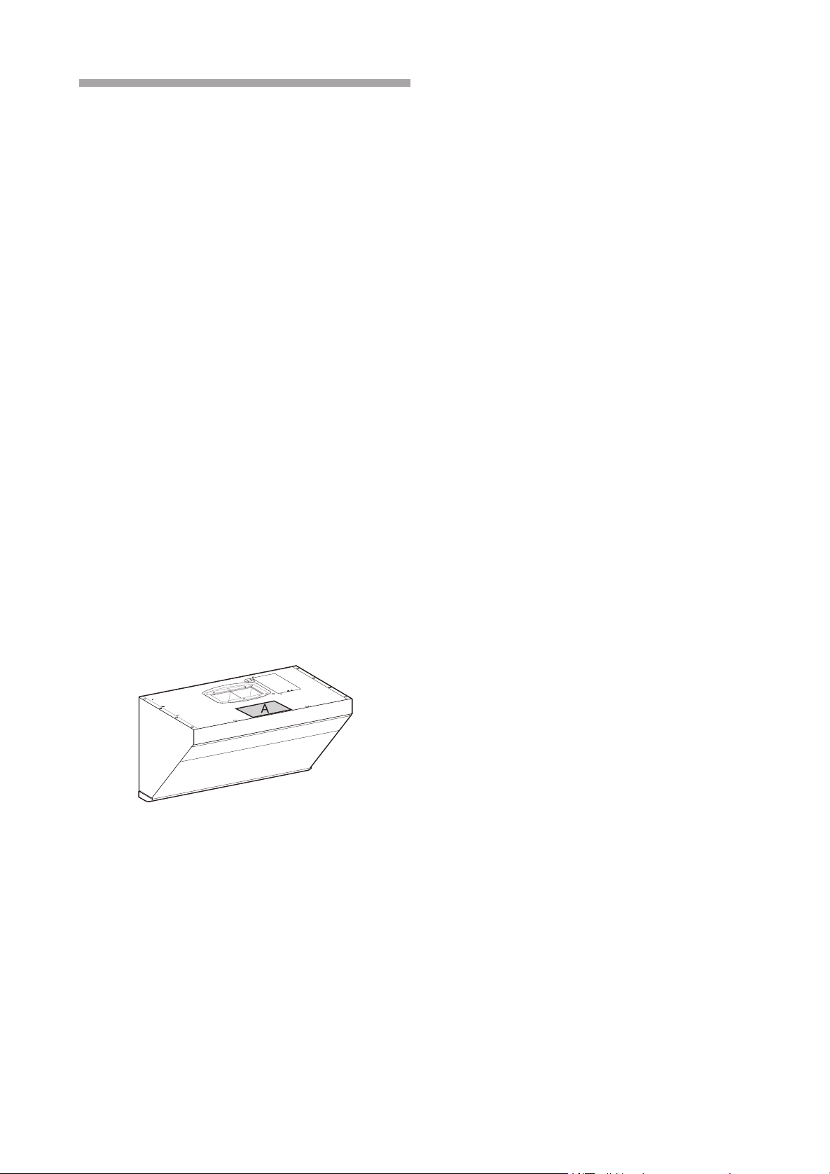
- 60 - - 61 -
Installation
6.1 Instructions d’installation
NOTE :
• Veuillez lire les instructions avant l’installation
et conserver la notice de montage pour la
référence de l’inspecteur local ou pour une
réutilisation ultérieure.
• Cet appareil doit être installé conformément au
Code Electrique National, ainsi que tous les
codes étatiques, municipaux et locaux.
• Protégez le produit par un disjoncteur adapté
et une mise à la terre efcace.
• Les caractéristiques nominales de tension, de
fréquence et d'ampérage sont répertoriés sur
la plaque d’identication du produit et doivent
être respectés.
• L’installation de l’appareil doit être effectuée
par le centre de service agréé de FOTILE ou
par un installateur autorisé.
• Avant l’installation de la hotte, La position de
la plaque peut se voir dans la gure A comme
suit .
• Le schéma suivant est le schéma de modèle
de base(JQG7505), veuillez vous reporter au
schéma du modèle de base pour les modèles
dérivés:
ATTENTION:
• Veuillez lire attentivement toutes les
instructions en respectant particulièrement les
consignes suivantes avant l’installation :
1. Si votre cuisine est en cours de rénovation,
n’exposez pas la hotte à l’air. Les matériaux
de construction, les poussières, la peinture et
les revêtements ainsi que leur gaz volatilisé
peuvent provoquer de la corrosion et ternir
les surfaces de l’appareil. Installez la hotte
aspirante après les travaux de rénovation de
votre cuisine.
2. Si vous devez déplacer la cuisinière à
courant avant le câblage, assurez-vous que
les mesures appropriées ont été prises pour
éviter la connexion inattendue.
4. La connexion électrique est interdite
pendant l’installation. Coupez l’alimentation par
la boîte d’alimentation principale. Si le câble
d’alimentation fourni est endommagé, il doit
être remplacé par un câble ou un ensemble
spécifique disponible auprès du fabricant ou
de ses revendeurs.
5. Une installation par l’utilisateur lui-même
peut constituer un danger d’électrocution,
de chute accidentelle et d’incendie. Le
démontage, l’installation et la réparation de
la hotte sont exclusivement réservés aux
professionnels.
Risque de blessures :
• Avant toute opération d’installation, de
nettoyage ou de réparation de l’appareil,
assurez-vous que le courant est coupé pour
éviter l’électrocution.
• Les arêtes de la hotte peuvent être très
vives : veuillez toujours porter des gants de
protection lorsque vous manipulez l’appareil
et particulièrement lorsque vous l’installez,
le nettoyez et le réparez, pour éviter les
blessures causées par les bords métallique de
l’appareil.
Avertissements avant installation
• Afin d’éviter des dommages à la hotte,
assurez-vous que des débris ne rentrent
pas dans l’orifice d’échappement. Estimez
l’emplacement du tuyau d’évacuation relié
à l’extérieur, reportez-vous aux schémas
d’installation.
• L’appareil atteint un rendement meilleur
lorsque le tuyau d’évacuation est droit et court.
• Si les tuyaux d’évacuation sont longs ou
présentent de nombreux coudes, la puissance
maximale d’aspiration ne sera pas atteinte.
• Evitez donc de les utiliser. Utiliser la colle de
tuyau pour étancher strictement la partie de
connexion entre le tuyau d’évacuation et le
trou dans le mur. Il faut assurer que le tuyau
d’évacuation est connecté fermement avec le
gaz avant l’installation de la hotte, fermez le
robinet du gaz avant de la déplacer.
3. L’air sortant de la hotte ne doit pas pénétrer
dans une cheminée en service destinée à
évacuer la fumée ou des gaz brûlés.
4. Compte tenu de la taille et du poids de la
hotte, il est recommandé de l’installer à deux
personnes, l’installation doit donc être effectuée
par des personnes professionnelles suivant les
instructions indiquées dans la notice.
5. Après que le produit est fixé, la fiche
électrique doit être accessible.
6. La hotte doit être fixée correctement en
respectant une parfaite horizontalité.
7. Vérifier que l’appareil ne présente aucune
anomalie en le mettant en service après
l’installation.
AVERTISSEMENT
• Pour réduire les risques d’incendie,
d’électrocution et de blessures, prêtez une
attention particulièrement aux instructions
suivantes :
1. L’installation et le câblage de la hotte
doivent être effectués par les personnes
professionnelles, conformément à toutes les
réglementations et les normes pertinentes, y
compris les instructions liées à l’incendie. Une
installation correcte est la responsabilité de
l’installateur. Les pannes du produit dues à une
mauvaise installation ne sont pas couvertes
par la garantie de FOTILE.
2. Pour assurer la sécurité et le bon
déroulement de l’installation, utiliser les
accessoires fournis avec l’appareil. Les trous
sur la paroi du mur doivent correspondre
précisément avec la taille des joints de
dilatation. Il est interdit de percer les trous trop
grands afin d’éviter l’instabilité des joints qui
peut provoquer une chute accidentelle !
3. La hotte aspirante doit être branchée sur
une prise de courant de mise à la terre efcace
et dédiée. Car l’électrocution, l’échauffement
des prises et l’incendie peuvent survenir
lors de la connexion de ligne d’alimentation
électrique, de l’utilisation de rallonge et de
dispositif de câblage multiport. Coupez le
couvercle d’orice, et étancher ceux-ci avec le
ruban adhésif à feuille d’aluminium.
• Si le trou est trop petit, le rendement de
l’appareil peut être réduit. Sur la base du
principe de sécurité, il est recommandé
d’élargir le trou à une taille du tuyau
d’évacuation égale ou supérieure à 6
pouces(152.4mm) pouces.
• Les boulons utilisés dans ce produit sont des
boulons de taille métrique, veuillez ne pas
utiliser les boulons non qualiés.
6.2 Dimensions du produit
187/16"
(467mm)
297/8"(758mm)
(JQG7505/JQG7505-W)
357/8"(910mm)
(JQG9006/JQG9006-W)
Wall installation
Le mur doit offrir une portance suffisante
pour supporter la hotte. Pour les murs
creux, l’épaisseur de sa partie solide doit
être supérieure à 13/16 pouces (30mm).
Pour les murs en béton, l’installation peut
être directement exploitée. La hotte doit être
solidement xée sur le mur.
Installation des tuyaux
Risque de blessures :
• Avant toute opération d’installation, de
nettoyage ou de réparation de l’appareil,
assurez-vous que le courant est coupé pour
éviter l’électrocution. Les arêtes de la hotte
peuvent être très vives : veuillez toujours
porter des gants de protection lorsque vous
manipulez l’appareil et particulièrement
lorsque vous l’installez, le nettoyez et le
réparez, pour éviter les blessures causées
par les bords métallique de l’appareil.
• Lorsque vous coupez ou percez un mur ou un
plafond, faites attention à ne pas endommager
le câblage électrique, les conduites d’eau ou
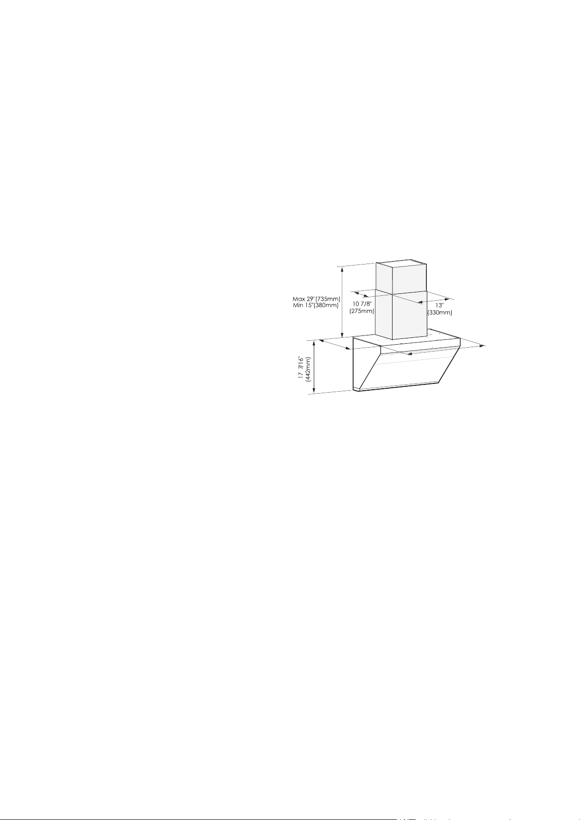
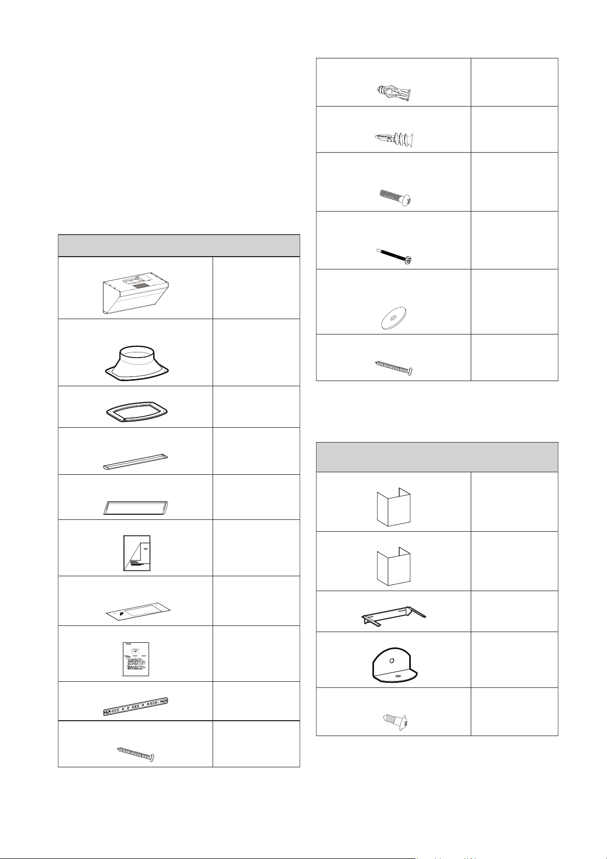
- 62 - - 63 -
de gaz et d’autres produits cachés.
• Le conduit de fumée doit toujours gagner
l’extérieur.
• Pour réduire le risque d’incendie, l’air sortant
doit être évacué à l’extérieur. Ne pas rejeter
l’air sortant dans des espaces à l’intérieur des
murs ou des plafonds, ni dans le grenier ou le
garage.
6.3 Liste des accessoires
Liste des produits dans l’emballage :
Conguration standard
Machine principale
1
Couvercle pour l’orice
d’échappement
1
Joint d’étanchéité
1
Coupe d’huile
(JQG7505/JQG7505-W)
1
Coupe d’huile
(JQG9006/JQG9006-W)
2
Notice d’utilisation
1
Papier sur les dimensions
d’installation
1
Carte de garantie
1
Accroche pour l’appareil principal
1
Boulon de crochet
#8×1 7/16"(ST4,2×36mm)
4
Boulon de crochet
#8×1 7/16"(ST4,2×36mm)
3
Tuyau d’expansion de carreau
φ1/4"×1 5/16"(φ5,3×32mm)
3
Tuyau d’expansion de plaque
φ3/16"×1 5/8"(φ4×40mm)
3
Vis #4×3/4"(ST2,9×19mm)
2
Accessoires pour l’installation de la plaque décorative
(à option)
Plaque décorative
6"(152,4mm) ou 4"(101,6mm)
1
Vis de xation pour la plaque
décorative
#6×1 7/16"(ST3,5×35mm)
4
Tuyau d’expansion de carreau
φ1/4"×1 5/16"(φ5,3×32mm)
4
Tuyau d’expansion de plaque
φ3/16"×1 5/8"(φ4×40mm)
4
Vis pour le couvercle d’orice
d’échappement
#8×3/4"(M4×18mm)
4
Vis de xation pour l’armoire du
dessus
#10×2 13/16"(M5×70mm)
4
( Une des vis
est une vis de
rechange)
Rondelle de vis de xation de
plaque d’armoire supérieure
φ1 5/16"(φ32mm)
4
(dont 1 de
secours)
Vis de bois
#10×2 9/16"(ST5×65mm)
4
Les accessoires ci-dessous sont à acheter
(auprès d'un point de vente agréé de Fotile)
Accessoires pour l’installation du capot extérieur
(à option)
Capot extérieur du ventilateur
1
Capot décoratif
1
Accroche pour le capot décoratif
1
Blocs de sécurité
1
Vis de support
#8×7/16"(M4×10mm)
4
6.4 Liste des produits dans l’emballage :
Marteau
Crayon
Tasseau
Niveau à bulle 1
Détecteur de bois
Ciseaux
Tournevis cruciforme
Équerre à dessine
Perceuse
Lunettes de protection
Cisailles
Mètre
Gants
Ruban adhésif
Scie
Tournevis électriquev
6.5 Procédure d’installation :
Afin de garantir la sécurité et l’optimalisation
du fonctionnement de l’appareil, nous vous
recommandons de l’installer à la hauteur
suivante : entre 9/16"(750mm) (compris) et
32 1/2"(825mm) (compris). Cette hauteur
d'installation convient uniquement à la cuisinière
électrique. Si la hotte est installée au-dessus
de la cuisinière à gaz, la distance min. entre la
surface d’appui de l'appareil de cuisson sur la
cuisinière et la partie la plus basse de la hotte
doit être d'au moins 24" (610mm) (Etats-Unis)
/ 25 5/8" (650mm) (Canada). Si les instructions
d'installation de la cuisinière à gaz demandent
une distance d'installation plus importante,
suivre ces instructions. La hauteur d'installation
de la hotte est une valeur recommandée, la
disposition de meuble et de hotte dans la
gure est uniquement à titre indicatif, lorsque la
hauteur d'installation du produit (c'est-à-dire la
distance entre la surface d’appui de l'appareil
de cuisson sur la cuisinière et la partie la plus
basse de la hotte) est inférieure à 24" ( 610mm)
(Etats-Unis) / 25 5/8" (650mm) (Canada),
toutes les pièces en dessous de 24"(610mm)
(Etats-Unis) / 25 5/8" (650mm) (Canada) sont
toutes les parties ininammables de la hotte ou
les pièces qui fonctionnent sous une tension
sûre et très basse, et lorsque ces pièces sont
déformées, cela n'affectera pas la protection
contre le contact avec les pièces sous tension.
Mieux vaut respecter, s’il y a lieu (Y compris,
mais sans s'y limiter, les règlements et normes
relatifs à l'architecture et à la lutte contre les
incendies), les dispositions du département
ou de la région locale relatives à l’installation
des hottes aspirantes, mais la performance
de l’appareil pourrait être considérablement
abaissée.
Il existe trois modes d’installation pour cet
appareil, avec ou sans l’armoire en haut.
Attention :
1. Au moins une des vis de bois(#10×2
9/16"(ST5×65mm)) de l’accroche de l’appareil
principal doit être xée sur une poutre en bois.
2. S'il y a besoin de creuser une ouverture de
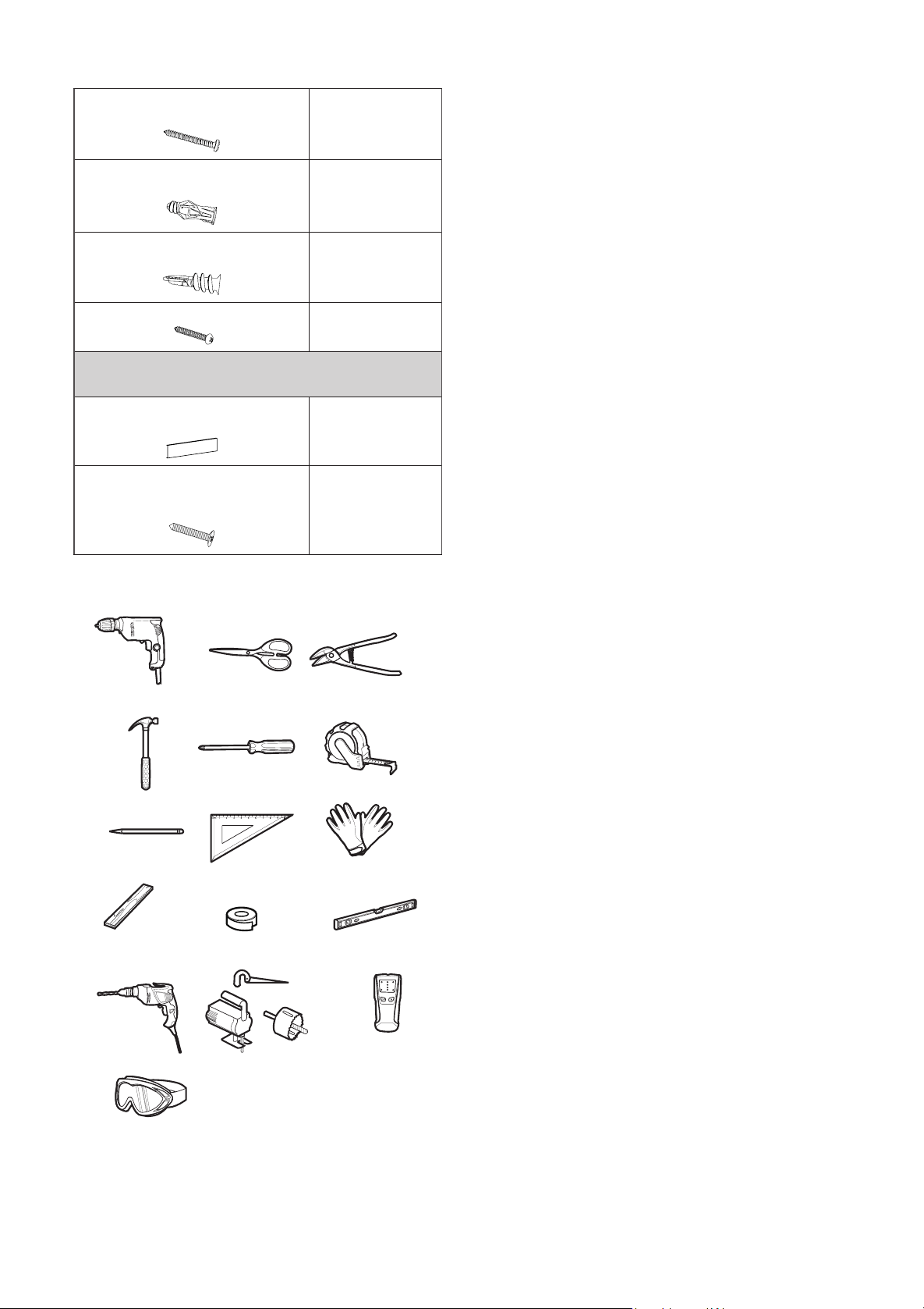
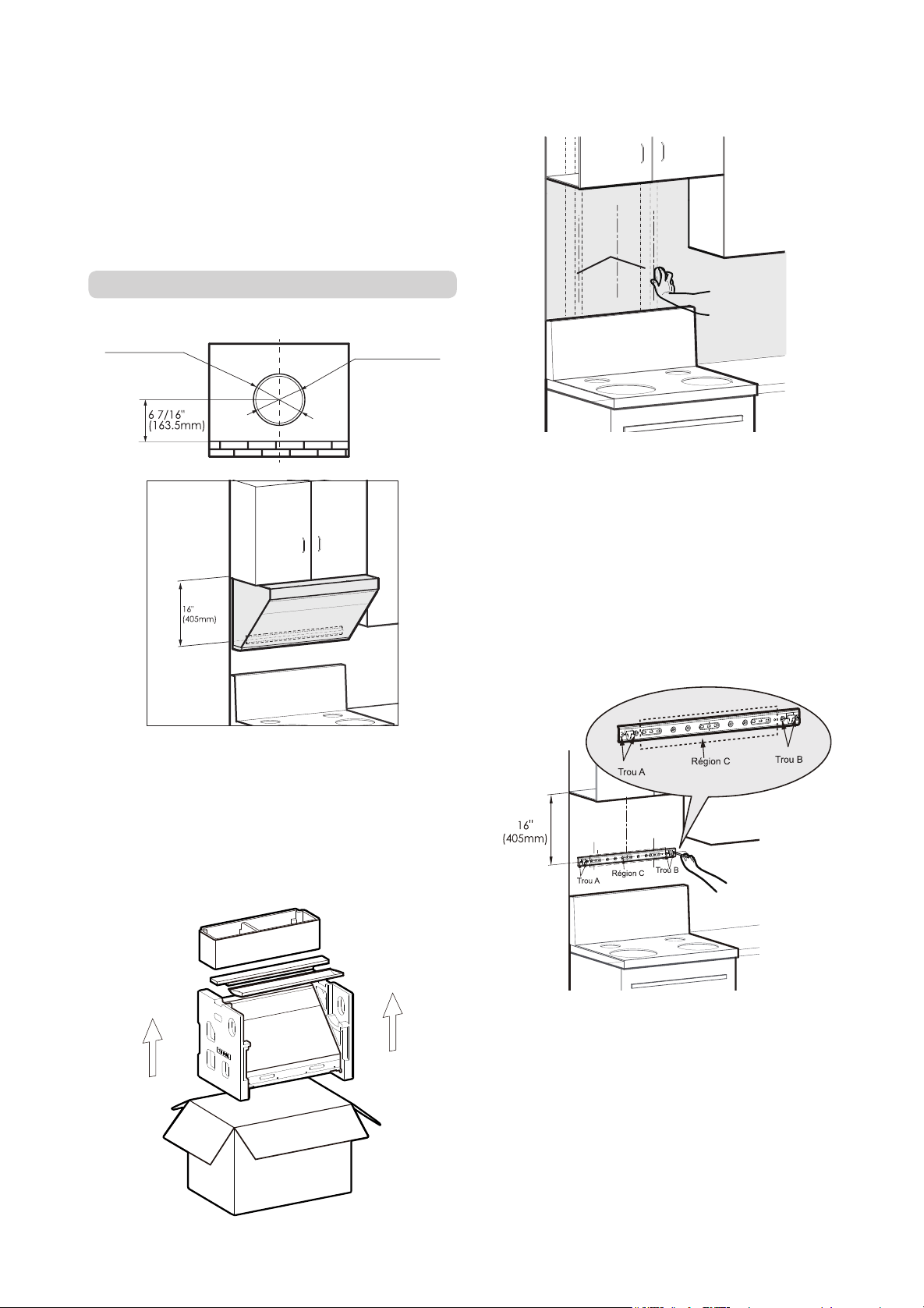
- 64 - - 65 -
la gaine à l'extérieur du mur d'appui. Nous vous
conseillons une distance minimale de 8" (20cm)
entre le plan du haut de la hotte aspirante et le
point central de l'ouverture.
Avertissement :
Une hauteur d'installation trop
basse peut provoquer une surchauffe du panneau
de verre, ce qui accroît les risques de rupture.
Avec armoire supérieure :
Diamètre de tuyau
d’évacuation
Φ6" (152.5mm)
Diamètre du trou
dans le mur
Φ6 1/2" (165mm)
Avertissement:
Veuillez toujours porter des
gants de protection lorsque vous manipulez
l’appareil
.
1. Ouvrez l’emballage, sortez l’appareil
principal et vériez les accessoires avec la liste
d’accessoires.
(marbre) : percer de trou φ3/8"(φ8mm) au
repérage de perçage et poser le tuyau d’expansion
de carreau(φ1/4"×1 5/16"(φ5.3×32mm)), fixer
le crochet avec la boulon de crochet(#8×1
716"(ST4.2×36mm)) de crochet et utiliser la règle
pour assurer l’horizontalité du crochet.
2) Au repérage de perçage, s’il s’agit de la plaque :
serrer la tuyau d’expansion de plaque(φ3/16"×1
5/8"(φ4×40mm)) avec le tournevis dans le
mur, puis fixer le crochet avec la boulon de
crochet(#8×1 716"(ST4.2×36mm)) de crochet
et utiliser la règle pour assurer l’horizontalité du
crochet.
5.Collez le papier de l'ouverture sur le bas
de la paroi supérieure avec la face indiquant
la dimension de l'ouverture vers le bas. Puis
creusez l'ouverture selon les instructions.
Attention:
portez des lunettes de protection
pour percer les trous.
Dans le cas où il y a du bois du côté de mur,
le côté de mur du papier d’installation doit être
coupé en fonction de l’épaisseur du bois.
Si les crochets sont fixés sur les carreaux
vernissés, le côté Rear Wall du papier de
l'ouverture doit être collé sur le bas de la paroi
en tenant le plan des carreaux vernissés comme
repère.
2. Identifiez le bois pour fixer l’accroche à la
position d’installation.
poteau de
bois du mur
3. Déterminez l’emplacement de l’accroche
de fixation de l’appareil principal : identifiez
le centre d’installation de la hotte, puis tracez
une ligne médiane verticale. Déterminez
l’emplacement de l’accroche avec comme
référence le point le plus bas du fond de
l'armoire du dessus. Marquez ensuite les
emplacements de perçage. La distance entre
le point le plus bas du fond de l’armoire et le
centre du crochet est 16"(405mm).
Attention:
Il faut mettre les vis de fixation
dans les trous A et B illustrés dans la figure.
La partie de la position du trou de crochet
dans la zone C, qui est correspondante au
pieu, doit être équipée des vis de bois(#10×2
9/16"(ST5×65mm)) de xation.
4. Crochet de xation:
1) Au repérage de perçage, s’il s’agit de carreau
6. Enlevez le lm protecteur sur la surface des
deux côtés de l’appareil et sur la coupe d’huile.
7. Soulevez l’appareil principal. Accrochez
d’abord la machine sur l’accroche en l’inclinant,
à l’aide du trou qui se trouve sur le bas de
l’arrière de l’appareil. Poussez ensuite la hotte
contre le mur.
Attention :
Pour plus de sécurité, il faut deux
personnes pour installer la hotte.
8. Utiliser 3 vis de fixation de plaque d’armoire
supérieure #10×2 13/16"(M5×70mm) et la
rondelle de vis de plaque d’armoire supérieure (φ1
516"(φ32mm))pour xer l’unité principale, et xer
au moins deux vis avant de relâcher la main.
Le fond de
l'armoire
Corps de hotte
S'il existe une fente relativement grosse entre le
fond de l'armoire et l'appareil principal, veuillez
ajouter un morceau de bois près des 3 vis de
dimension #10×2 13/16"(M5×70mm) selon la
taille de la fente avant l'installation de l'appareil
an d'éviter la déformation de l'appareil durant la
xation des vis.
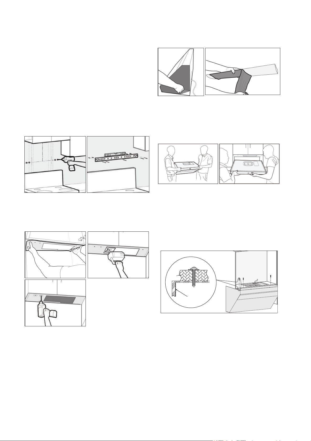
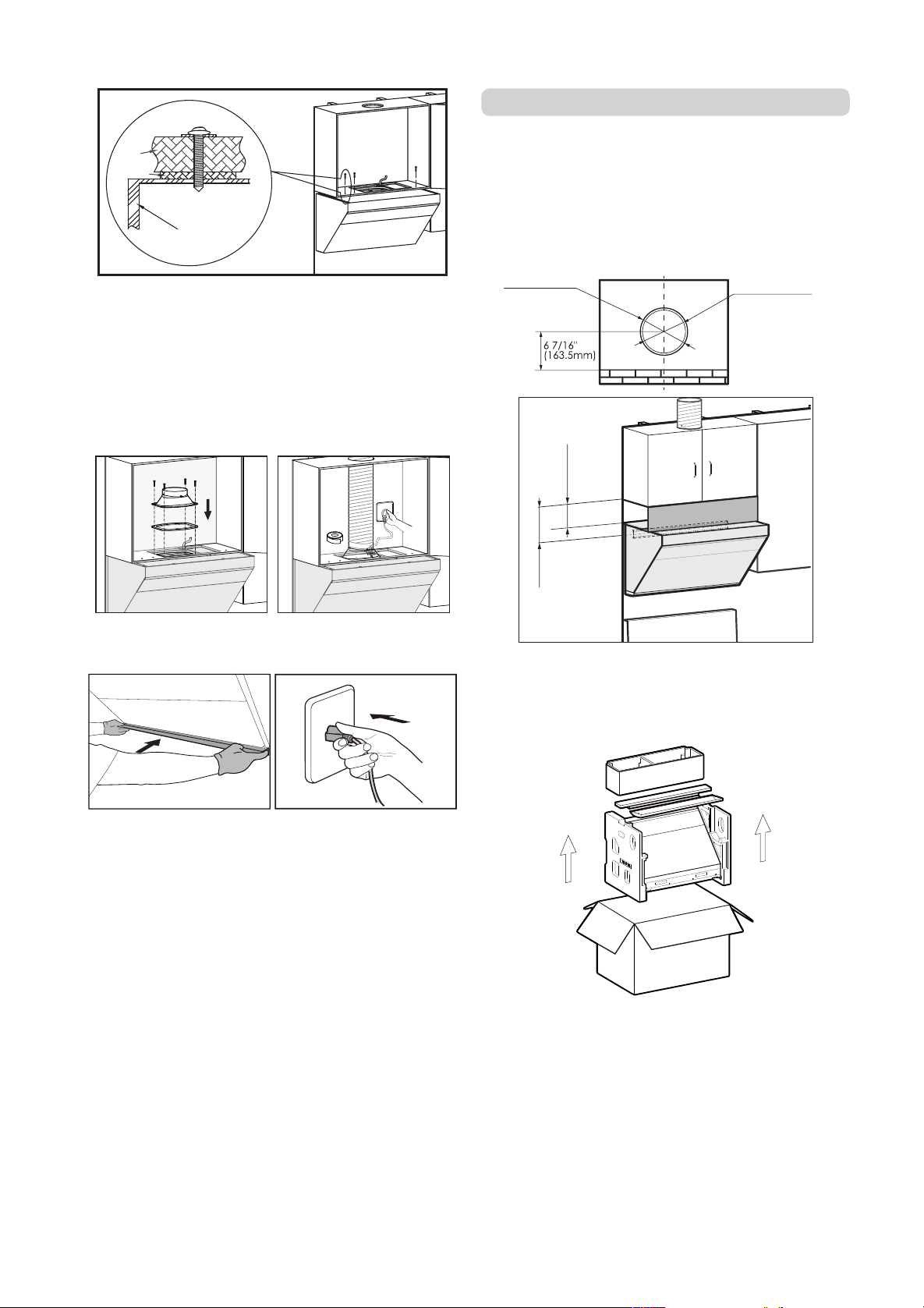
- 66 - - 67 -
Corps de hotte
Le fond de
l'armoire
Plaque en bois
9. Placer le joint d'étanchéité (l’encoche vers
le bas) à la sortie d'air de la machine et xer le
boîtier de sortie avec 4 vis-boîtier de sortie de
# 8 x 3/4" (M4 × 18 mm). Puis xez le tuyau sur
le couvercle d’orifice et scellez avec du ruban
d’aluminium.
10. Make sure the hood is leveled. Install the oil
cup, and plug in the appliance for a test run.
Attention :
Au moins une des vis doit être xée
sur une poutre en bois.
Attention:
Veuillez faire fonctionner la machine
et vériez s'il y a une fuite d'air dans le tuyau de
fumée après avoir scellé le tuyau avec du ruban
adhésif en aluminium. Le tuyau de fumée doit
être redressé autant que possible.
1. Ouvrez l’emballage, sortez l’appareil
principal et vériez les accessoires avec la liste
d’accessoires.
Avec armoire supérieure + capot décoratif
Attention :
Veillez vérier d'abord la hauteur de
l'armoire supérieure. Si celle - ci dépasse 32
1/2 pouces (825mm), les plaques décoratives
de 6 pouces(152.4mm) ou 4 pouces(101.6mm)
pouces peuvent être utilisées.
Diamètre de tuyau
d’évacuation
Φ6" (152.5mm)
Diamètre du trou
dans le mur
Φ6 1/2" (165mm)
7 11/16"(194.4mm)
or
5 11/16"(143.6mm)
6"(152.4mm)
or
4"(101.6mm)
2. Identifiez le bois pour fixer l’accroche à la
position d’installation.
poteau de
bois du mur
3. Déterminez l’emplacement de l’accroche de
xation de l’appareil principal : identiez le centre
d’installation de la hotte, puis tracez une ligne
médiane verticale. Déterminez l’emplacement
de l’accroche avec comme référence la plaque
de l'armoire du dessus. Marquez ensuite les
emplacements de perçage. Le bord en haut de la
planche de fond de l’armoire en haut (la surface
fixe de la planche décorative et de la planche
de fond) étant le repère, la distance au centre
du crochet est : 6 pouces la planche décorative
de 7 11/16"(194.4mm) et 4 pouces la planche
décorative de 5 11/16"(143.6mm).
Le bord en haut de la planche
de fond de l’armoire en haut
(la surface fixe de la planche
décorative et de la planche de
fond) étant le repËre.
5 11/16"
(143.6mm)
or
7 11/16"
(194.4mm)
Attention:
Au moins une des vis de bois(#10×2
9/16"(ST5×65mm)) du crochet de l’appareil
principal doit être fixée sur la poutre en bois.
Il faut mettre les vis de fixation dans les trous
A et B illustrés dans la figure. La partie de la
position du trou de crochet dans la zone C, qui
est correspondante au pieu, doit être équipée
des vis de bois(#10×2 9/16"(ST5×65mm)) de
xation.
4.
Crochet de xation:
1) Au repérage de perçage, s’il s’agit de
carreau (marbre) : percer de trou φ3/8"(φ8mm)
au repérage de perçage et poser le
tuyau d’expansion de carreau(φ1/4"×1
5/16"(φ5.3×32mm)), fixer le crochet avec la
boulon de crochet(#8×1 716"(ST4.2×36mm))
de crochet et utiliser la règle pour assurer
l’horizontalité du crochet.
2) Au repérage de perçage, s’il s’agit de
la plaque : serrer la tuyau d’expansion de
plaque(φ3/16"×1 5/8"(φ4×40mm)) avec le
tournevis dans le mur, puis xer le crochet avec
la boulon de crochet(#8×1 716"(ST4.2×36mm))
de crochet et utiliser la règle pour assurer
l’horizontalité du crochet.
5.Collez le papier de l'ouverture sur le bas
de la paroi supérieure avec la face indiquant
la dimension de l'ouverture vers le bas. Puis
creusez l'ouverture selon les instructions.
Attention:
portez des lunettes de protection
pour percer les trous.
Dans le cas où il y a du bois du côté de mur,
le côté de mur du papier d’installation doit être
coupé en fonction de l’épaisseur du bois.
Si les crochets sont fixés sur les carreaux
vernissés, le côté Rear Wall du papier de
l'ouverture doit être collé sur le bas de la paroi
en tenant le plan des carreaux vernissés comme
repère.
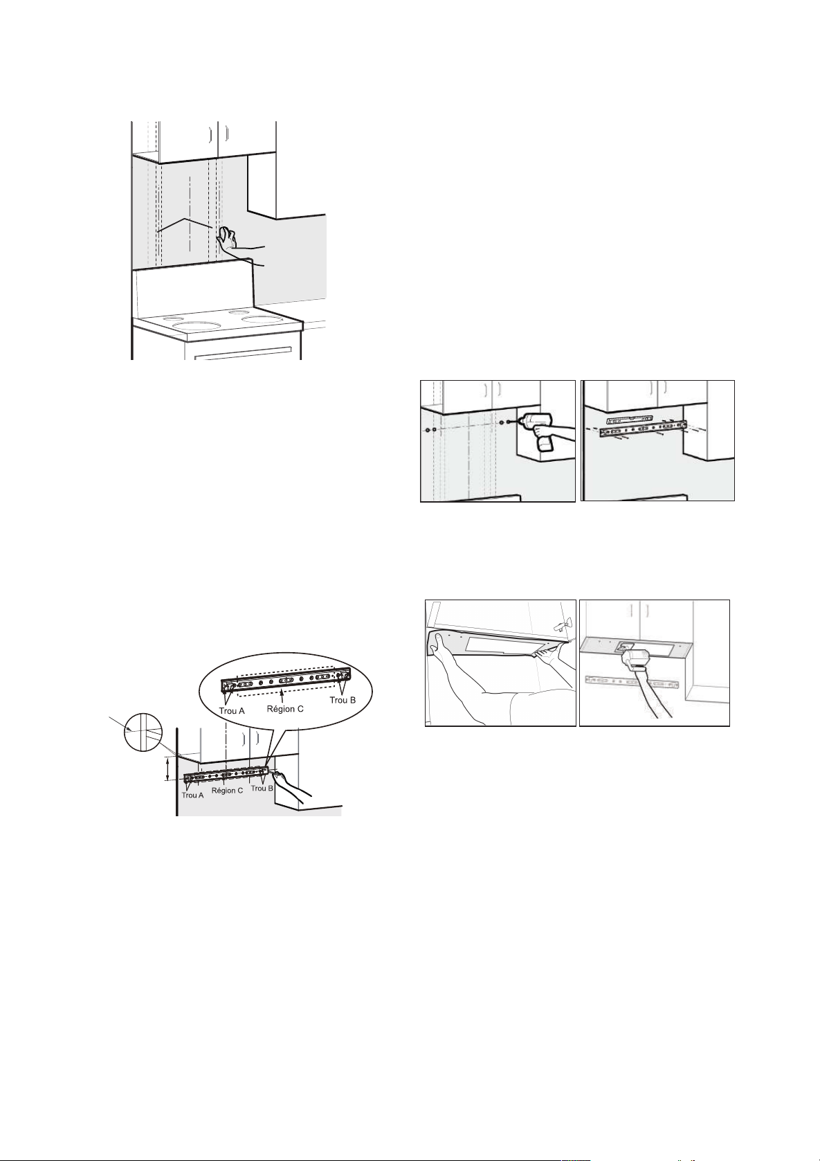
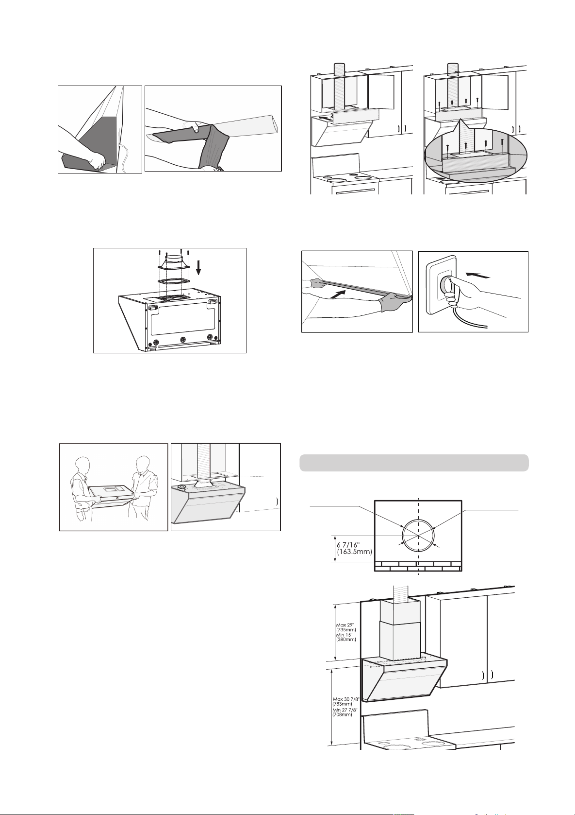
- 68 - - 69 -
10. La hotte doit avoir une parfaite horizontalité.
Installez la coupe d’huile. Branchez la hotte pour
vérier son fonctionnement.
Attention :
Au moins une des vis doit être xée
sur une poutre en bois.
Attention:
Veuillez faire fonctionner la machine
et vériez s'il y a une fuite d'air dans le tuyau de
fumée après avoir scellé le tuyau avec du ruban
adhésif en aluminium. Le tuyau de fumée doit
être redressé autant que possible.
Sans armoire supérieure + capot décoratif
Diamètre de tuyau
d’évacuation
Φ6" (152.5mm)
Diamètre du trou
dans le mur
Φ6 1/2" (165mm)
6. Enlevez le lm protecteur sur la surface des
deux côtés de l’appareil et sur la coupe d’huile.
7. Placer le joint d'étanchéité (l’encoche vers
le bas) à la sortie d'air de la machine et xer le
boîtier de sortie avec 4 vis-boîtier de sortie de #
8 x 3/4" (M4 × 18 mm).
8. Soulever l’appareil principal et mettre le
crochet dans le trou correspondant qui se
trouve sur le haut de l’arrière de l’appareil. Puis
xez le tuyau sur le couvercle d’orice et scellez
avec du ruban d’aluminium.
Attention :
Pour plus de sécurité, il faut deux
personnes pour installer la hotte.
9. Fixez la planche décorative avec 4 vis à bois
#6×1 7/16"(ST3.5×35mm). Fixez la planche
décorative sur la paroi supérieure. (Les vis à
bois sont dans le paquet d'accessoires qui se
trouve lui-même dans la boîte d'emballage de la
planche décorative)
1. Ouvrez l’emballage, sortez l’appareil principal et
vériez les accessoires avec la liste d’accessoires.
2. Identifiez le bois pour fixer l’accroche à la
position d’installation.
poteau de
bois du mur
3.Identiez le centre d'installation de la hotte en
se référant au centre de la table de cuisson.
2
5
/1
6
"(
5
8
.5
m
m
)
4
9
/1
6
"(
11
5
.5
m
m
)
Max 29 15/16"(760mm)
Max 30 7/8"(783mm)
Min 27 7/8"(708mm)
4
9/16"(115.5mm)
Trou A
Aégion C
Trou B
Trou A
Aégion C
Trou B
Trou pour
l'installation
du bloc de
sécurité
Attention:
Au moins une des vis de bois(#10×2
9/16"(ST5×65mm)) du crochet de l’appareil
principal doit être fixée sur la poutre en bois.
Il faut mettre les vis de fixation dans les trous
A et B illustrés dans la figure. La partie de la
position du trou de crochet dans la zone C, qui
est correspondante au pieu, doit être équipée
des vis de bois(#10×2 9/16"(ST5×65mm)) de
xation.
Déterminez ensuite l'emplacement de
l'accroche en se référant au niveau de la
surface de table de cuisson et marquez les
emplacements de perçage. La dimension entre
la surface de table de cuisson et le centre de
l'accroche est de 27 7/8 pouces (708mm) - 30
7/8 pouces (783mm).
Les bouchons de sécurité : décalez d’abord 4
9/16 pouces (115,5mm), vers droite de la partie
supérieure de l’accroche, ensuite 2 5/16 pouces
(58,5mm) vers le haut.
Pour l’accroche pour le capot extérieur décoratif,
Les dimensions générales sont comme suit : 29
15/16 pouces (760mm) au dessus du centre de
l’accroche de l’appareil principal. Si le plafond
se trouve à l’intérieur de cette distance, alignez
l’accroche avec le plafond. Si le plafond se
trouve au dessus de cette distance, il faut
acheter séparément un capot décoratif allongé.
Les hauteurs du capot décoratif allongé sont
respectivement : 27 9/16 pouces (700mm) et 35
7/16 (900mm).
Poser le tuyau d’expansion sur le repérage de
perçage:
1) Au repérage de perçage, s’il s’agit de
carreau (marbre) : percer de trou φ3/8"(φ8mm)
au repérage de perçage et poser le
tuyau d’expansion de carreau(φ1/4"×1
5/16"(φ5.3×32mm)).
2) Au repérage de perçage, s’il s’agit de la plaque :
serrer la tuyau d’expansion de plaque(φ3/16"×1
5/8"(φ4×40mm)) avec le tournevis dans le mur.
4. Fixez l’accroche pour machine principale et
le capot décoratif avec les vis correspondantes,
vissez les vis et vériez le niveau de l’accroche.
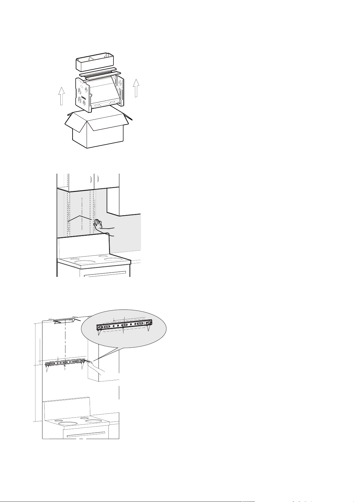
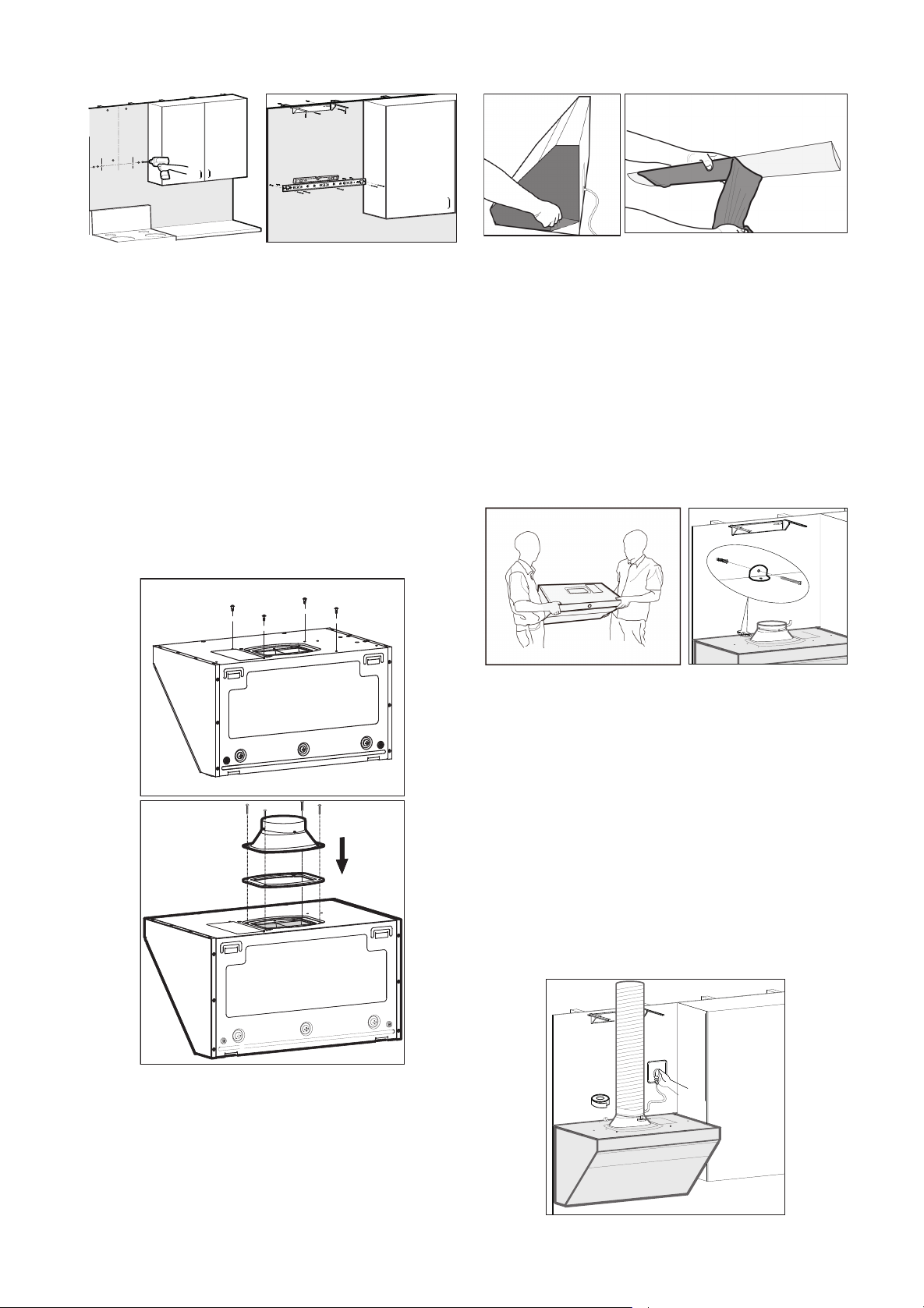
- 70 - - 71 -
7. Soulevez l’appareil principal. Accrochez
d’abord la machine sur l’accroche grâce au trou
qui se trouve sur le haut de l’arrière de l’appareil.
Stabilisez la hotte et vérifiez son horizontalité
à l’aide d’un niveau à bulle. Fixez ensuite les
bouchons de sécurité au-dessus de la hotte(Le
cran de sûreté se trouve dans le paquet
d'accessoires qui se trouve lui-même dans la
boîte d'emballage des pièces composantes de
l'enveloppe décorative.).
Attention:
Pour plus de sécurité, il faut deux
personnes pour installer la hotte. Installez
le cran de sûreté selon les instructions. La
fonction principale du cran de sûreté est d'éviter
la tombée de la hotte aspirante à la suite d'un
décrochage dû à une élévation accidentelle de
l'appareil.
8. Fixez le tuyau sur le couvercle d’orifice et
scellez avec du ruban d’aluminium. L’appareil
doit être xée correctement en respectant une
parfaite horizontalité et branchez la hotte.
Attention :
Au moins une des vis de bois(#10×2
9/16"(ST5×65mm)) de l’accroche de l’appareil
principal doit être xée sur une poutre en bois.
5. Placer le joint d'étanchéité (l’encoche vers
le bas) à la sortie d'air de la machine et fixer le
boîtier de sortie avec 4 vis-boîtier de sortie de # 8
x 3/4" (M4 × 18 mm). Fixez les quatre vis du capot
extérieur #8×7/16"(M4×10mm) dans les positions
correspondantes
(Les vis d'enveloppe trouvent
dans le paquet d'accessoires qui se trouve lui-
même dans la boîte d'emballage des pièces
composantes de l'enveloppe décorative.).
6. Enlevez le lm protecteur sur la surface des
deux côtés de l’appareil et sur la coupe d’huile.
Attention:
Veuillez faire fonctionner la machine
et vériez s'il y a une fuite d'air dans le tuyau de
fumée après avoir scellé le tuyau avec du ruban
adhésif en aluminium. Le tuyau de fumée doit être
redressé autant que possible.
9. Enlevez d'abord le film de protection de
l'enveloppe décorative et celui de l'enveloppe du
ventilateur. Mettez l'enveloppe décorative dans
l'enveloppe du ventilateur. Puis prenez en même
temps l'enveloppe décorative et l'enveloppe du
ventilateur. Accrochez l'enveloppe décorative sur
les crochets correspondants, puis descendez
lentement l'enveloppe du ventilateur. Poussez vers
l'intérieur l'enveloppe décorative et l'enveloppe
du ventilateur jusqu'à ce que l'enveloppe du
ventilateur soit attachée aux vis correspondantes.
10. Installez la coupe d’huile.
Avertissement:
Veillez porter des gants de
protection.
6.6 Test après l’installation
1. Appuyez sur la touche Marche/Arrêt, puis sur
la touche Eclairage. Vériez le fonctionnement de
l’éclairage et l’ouverture automatique de l’écran
de fumée.
2. Appuyez sur les touches de ventilateur pour
vérier le fonctionnement du moteur. En cas des
anomalies suivantes, coupez immédiatement
l’alimentation et arrêtez le fonctionnement.
Vériez ensuite si le problème vient de l’installation
(Contactez rapidement notre centre de service
après-vente local si les dysfonctionnements sont
conrmés) :
(1) Fortes vibrations de l’appareil
.
(2) Les turbines ne tournent pas.
(3) Du bruit de frottement apparent se produit lors
de la rotation des turbines.
(4) Du bruit anormal du moteur se produit.
3. Appuyez sur la touche Marche/Arrêt, le
ventilateur s’arrête et l’écran de fumée se ferme
automatiquement.
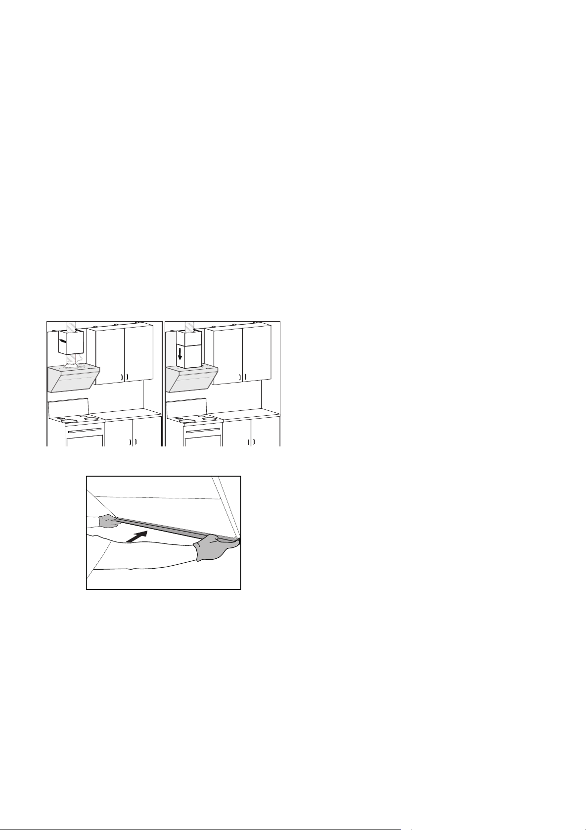
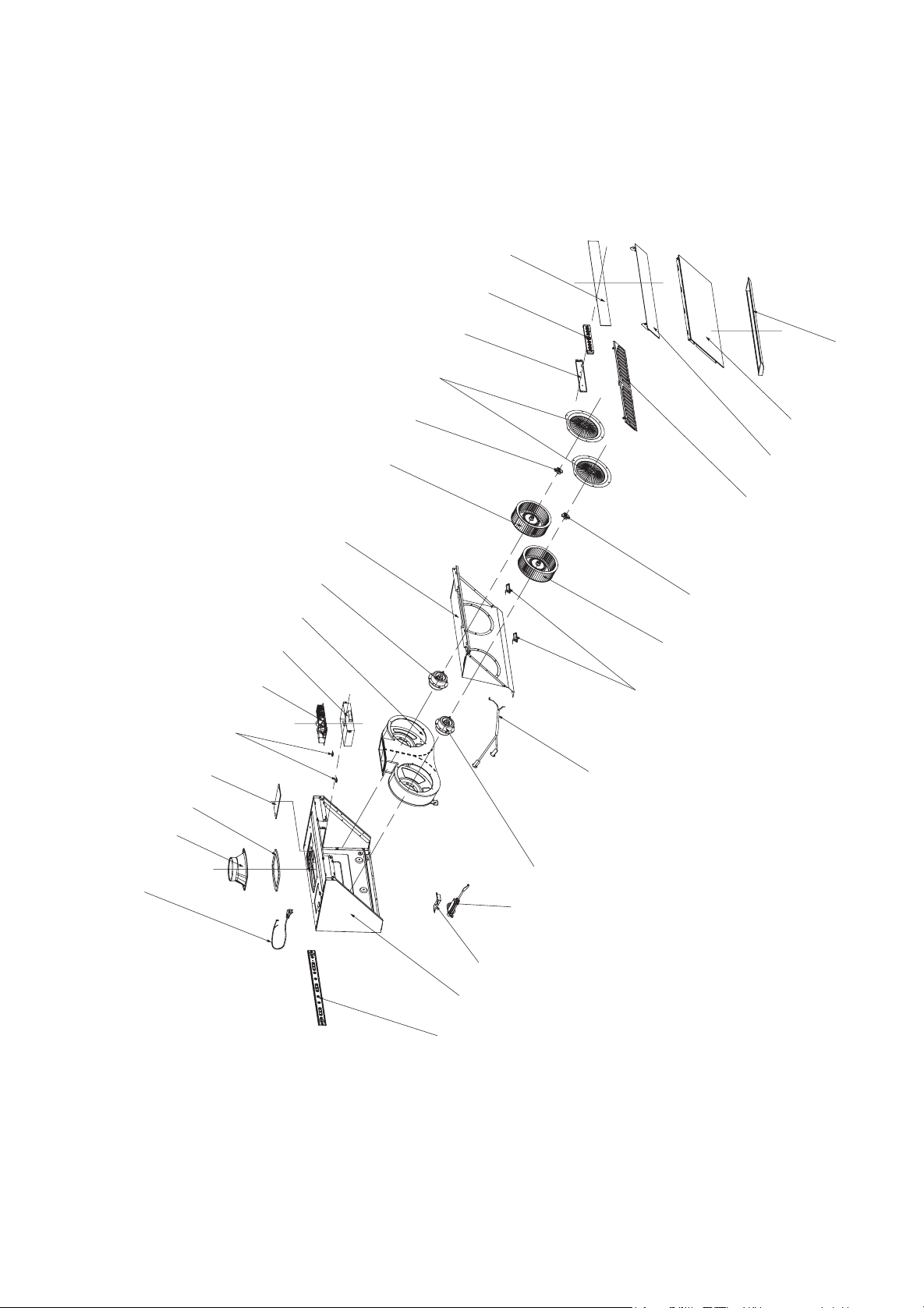
Vue exploséeJQG7505/JQG7505-W
lignes Èlectrique
Couvercle pour l’orifice d’échappement
Joint d’étanchéité
couvercle du boÓtier Èlectrique
Bloc d’appui de la boîte électrique
Plaquette d’alimentation
boîte électrique
Volute
moteur(droite)
moteur(gauche)
Plaque de guidage dí huile
aubes (droite)
aubes (gauche)
Ècrou manuel (droite)
anneau dí entrÈe dí air
LED
Accroche pour l’appareil principal
plaque de contrôle
composant du panneau de contrôle
composant du verre supérieur
coupe dí huile
verre infÈrieur
verre de lí Ècran de fumÈe
filtre ‡ graisse
composant du câble de connexio
tige Èlectrique
Support de la tige
Machine principale
JQG9006/JQG9006-W
lignes Èlectrique
Couvercle pour l’orifice d’échappement
Joint d’étanchéité
couvercle du boÓtier Èlectrique
Bloc d’appui de la boîte électrique
Plaquette d’alimentation
boîte électrique
Volute
moteur(droite)
moteur(gauche)
Plaque de guidage dí huile
aubes (droite)
aubes (gauche)
Ècrou manuel (droite)
Ècrou manuel (gauche)
anneau dí entrÈe dí air
LED
Couvercle de poussoir
Accroche pour l’appareil principal
plaque de contrôle
composant du panneau de contrôle
composant du verre supérieur
coupe dí huile
verre infÈrieur
verre de lí Ècran de fumÈe
filtre ‡ graisse (droite)
filtre ‡ graisse (gauche)
composant du câble de connexio
tige Èlectrique
Support de la tige
Machine principale
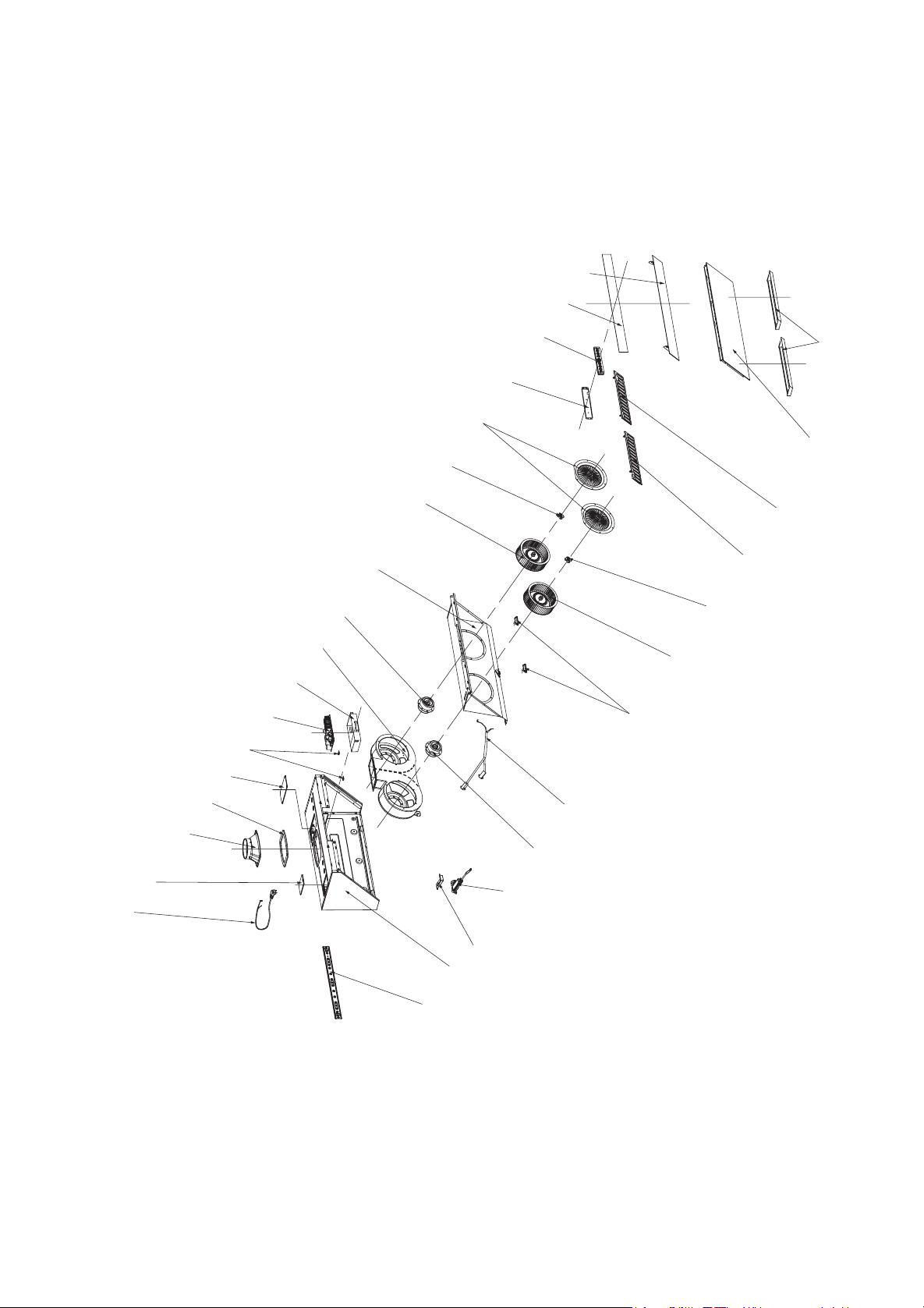

110100052648E

110100052648E

- 20 -
User Manual
RANGE HOOD
Please read the following safety information carefully before installing and/or using this appliance.
We recommend that you keep this manual for future use and/or in case of transfer of ownership
of the range hood
JQG7505/JQG7505-W/JQG9006/JQG9006-W