WWW.ZEPHYRONLINE.COM
JAN21.0101
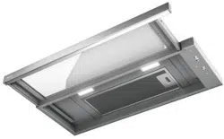
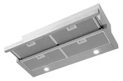
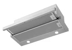
Pisa
ZPI-E24BG, ZPI-E24BG290
ZPI-E24BW, ZPI-E24BW290
ZPI-E30BG, ZPI-E30BG290
ZPI-E30BW, ZPI-E30BW290
ZPI-E36BG, ZPI-E36BG290
EN Use, Care, and Installation Guide
FR Guide d’utilisation, d’entretien et d’installation

2
Pisa Use, Care, and Installation Guide
PISA
UNDERCABINET
CORE

3
Pisa Use, Care, and Installation Guide
ZEPHYRONLINE.COM
Contents
Page
Safety Information ............................................................................ 4-6
Types of Safety Warnings ................................................................... 4
General Safety ..................................................................................4-5
Operation ........................................................................................... 6
Electrical Requirements ...................................................................... 6
List of Materials ................................................................................... 7
Installation Instructions .................................................................... 8-20
Ducting Calculation Sheet .................................................................. 8
Mounting Height, Clearance, & Ducting ...........................................9-10
Ducting Options .................................................................................11
Hood Specifications ............................................................................12
Electrical Supply .................................................................................13
Cable Lock .........................................................................................13
Preparing the Cabinet ........................................................................14
Horizontal Ducting Conversion ...........................................................15
Mounting the Hood .......................................................................... 16-18
Ductless Recirculation .....................................................................19-20
Features & Controls ............................................................................ 21
Slide Controls .....................................................................................21
Maintenance ................................................................................... 22-23
Hood & Filter Cleaning .....................................................................22-23
LumiLight LED ................................................................................... 23
Wiring Diagram ..................................................................................24
Troubleshooting............................................................................... 25-26
List of Parts & Accessories .................................................................. 27
Notes ..................................................................................................28
Limited Warranty ...............................................................................29
Product Registration ...........................................................................30
4
Pisa Use, Care, and Installation Guide
PISA
UNDERCABINET
CORE
Safety Information
Your safety and the safety of others are very important.
We have provided many important safety messages in this
manual for your appliance. Always read and obey all safety
messages.
This is the Safety Alert Symbol. This symbol alerts you to
potential hazards that can cause severe bodily injury or death.
All safety messages will follow the Safety Alert Symbol and either
the words “DANGER” “WARNING” or “CAUTION”
DANGER
Danger means that failure to heed this safety statement may
result in severe injury or death.
READ AND SAVE THESE INSTRUCTIONS
WARNING - TO REDUCE THE RISK OF FIRE, ELECTRIC SHOCK,
OR INJURY TO PERSONS, OBSERVE THE FOLLOWING:
a) Use this unit only in the manner intended by the
manufacturer. If you have questions, contact the manufacturer.
b) Before servicing or cleaning unit, switch power o at service
panel and lock the service disconnecting means to prevent
power from being switched on accidentally. When the service
disconnecting means cannot be locked, securely fasten a
prominent warning device, such as a tag, to the service panel.
General Safety
WARNING
Warning means that failure to heed this safety statement
may result in extensive product damage, serious personal
injury, or death.
CAUTION
Caution means that failure to heed this safety statement
may result in minor or moderate personal injury, property or
equipment damage.
WARNING
To reduce the risk of fire or electric shock, do not use this fan
with any solid-state control device.
WARNING
CAUTION
For General Ventilating Use Only. Do Not Use To Exhaust
Hazardous Or Explosive Materials And Vapors. Take care
when using cleaning agents or detergents. Suitable for use in
household cooking area.
WARNING
WARNING - TO REDUCE THE RISK OF A RANGE TOP GREASE
FIRE:
a) Never leave surface units unattended at high settings.
Boilovers cause smoking and greasy spillovers that may ignite.
Heat oils slowly on low or medium settings.
b) Always turn hood ON when cooking at high heat or
when flambeing food. (i.e. Crepes Suzette, Cherries Jubilee,
Peppercorn Beef Flambe’).
c) Clean ventilating fans frequently. Grease should not be
allowed to accumulate on fan or filter.
d) Use proper pan size. Always use cookware appropriate for
the size of the surface element.
5
Pisa Use, Care, and Installation Guide
ZEPHYRONLINE.COM
Safety Information
WARNING
READ AND SAVE THESE INSTRUCTIONS
WARNING - TO REDUCE THE RISK OF INJURY TO PERSONS
IN THE EVENT OF A RANGE TOP GREASE FIRE, OBSERVE THE
FOLLOWING:
a) SMOTHER FLAMES with a close-fitting lid, cookie sheet, or
metal tray, then turn o the burner. BE CAREFUL TO PREVENT
BURNS. If the flames do not go out immediately, EVACUATE AND
CALL THE FIRE DEPARTMENT.
b) NEVER PICK UP A FLAMING PAN – You may be burned.
c) DO NOT USE WATER, including wet dishcloths or towels – a
violent steam explosion will result.
d) Use an extinguisher ONLY if:
1) You know you have a Class ABC extinguisher, and you
already know how to operate it.
2) The fire is small and contained in the area where it
started.
3) The fire department is being called.
4) You can fight the fire with your back to an exit
Based on “Kitchen Firesafety Tips” published by NFPA.
WARNING
WARNING
TO REDUCE THE RISK OF FIRE, USE ONLY METAL DUCTWORK.
CAUTION
To reduce risk of fire and to properly exhaust air outside, do
not vent exhaust air into spaces within walls, ceilings, attics,
crawl spaces, or garages.
WARNING
WARNING - TO REDUCE THE RISK OF FIRE, ELECTRIC SHOCK,
OR INJURY TO PERSONS, OBSERVE THE FOLLOWING:
a) Installation work and electrical wiring must be done by
qualified person(s) in accordance with all applicable codes and
standards, including fire-rated construction.
b) Sucient air is needed for proper combustion and
exhausting of gases through the flue (chimney) of fuel burning
equipment to prevent back drafting. Follow the heating
equipment manufacturer’s guideline and safety standards such
as those published by the National Fire Protection Association
(NFPA), and the American Society for Heating, Refrigeration
and Air Conditioning Engineers (ASHRAE), and the local code
authorities.
c) When cutting or drilling into wall or ceiling, do not damage
electrical wiring and other hidden utilities.
d) Ducted fans must always be vented to the outdoors.
e) If this unit is to be installed over a tub or shower, it must be
marked as appropriate for the application and be connected
to a GFCI (Ground Fault Circuit Interrupter) - protected branch
circuit.
WARNING
Prop. 65 Warning for California Residents: This product may
contain chemicals known to the State of California to cause
cancer, birth defects, or other reproductive harm.

6
Pisa Use, Care, and Installation Guide
PISA
UNDERCABINET
CORE
Safety Information
Operation
Ź Always leave safety grilles and filters in place. Without these components, operating blowers could catch onto hair, fingers and
loose clothing.
Ź The manufacturer declines all responsibility in the event of failure to observe the instructions given here for installation,
maintenance and suitable use of the product. The manufacturer further declines all responsibility for injury due to negligence and
the warranty of the unit automatically expires due to improper maintenance.
NOTE: Please check www.zephyronline.com for revisions before doing any custom work.
Electrical Requirements
Important:
Ź Observe all governing codes and ordinances.
Ź It is the customer’s responsibility to be aware of these below:
Ź To contact a qualified electrical installer.
Ź To assure that the electrical installation is adequate and in conformance with National Electrical Code, ANSI/NFPA 70 latest
edition* or CSA standards C22.1-94, Canadian Electrical Code, Part 1 and C22.2 No.0-M91 - latest edition** and all local codes
and ordinances.
Ź If codes permit and a separate ground wire is used, it is recommended that a qualified electrician determine that the ground path
is adequate.
Ź Do not ground to a gas pipe.
Ź Check with a qualified electrician if you are not sure the range hood is properly grounded.
Ź Do not have a fuse in the neutral or ground circuit.
Ź This appliance requires a 120V 60Hz electrical supply and connected to an individual properly grounded branch circuit protected
by a 15 or 20 ampere circuit breaker or time delay fuse. Wiring must be 2 wire with ground. Please also refer to Electrical Diagram
on product.
Ź A cable locking connector (not supplied) might also be required by local codes. Check with local requirements, purchase and
install appropriate connector if necessary.
* National Fire Protection Association Batterymarch Park, Quincy, Massachusetts 02269
** CSA International 8501 East Pleasant Valley Road, Cleveland, Ohio 44131-5575
READ AND SAVE THESE INSTRUCTIONS
7
Pisa Use, Care, and Installation Guide
ZEPHYRONLINE.COM
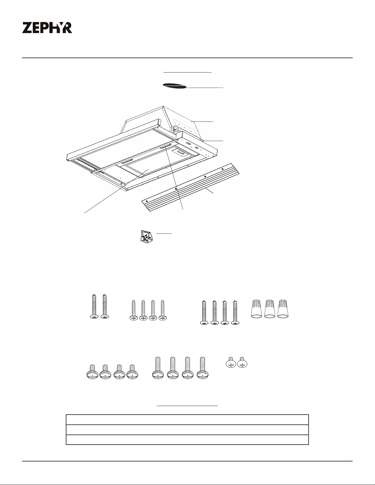
List of Materials
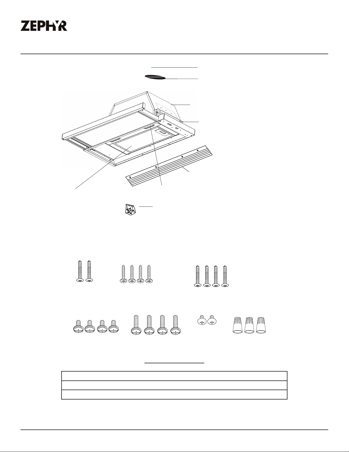
Parts Not Supplied
Ducting, conduit and all installation tools
Cable locking connector (if required by local codes)
Recirculating kit
Parts Supplied
(3) Wire Nuts
(1) 6” round damper (pre-installed)
(1) hardware package
HARDWARE PACKAGE CONTENTS
(1) LumiLight LED, 6W (24” model)
(2) LumiLight LED, 6W (30” & 36” models)
ĬŚĭŮ
(2) #6 x 1”
(1) hood body with sliding glass
ĬŚĭŮ
(4) M3.5x10 (24” model)
(5) M3.5x10 (30” & 36” models)
(4) M4 x 16mm
(30” & 36” models)
(2) upper installation brackets
(2) lower installation brackets
(24” model only)
(2) M4 x 8
(4) 3/16 x 3/8”
(4) 3/16 x 40
(24” model only)
(24” model only)
(24” model only)
8
Pisa Use, Care, and Installation Guide
PISA
UNDERCABINET
CORE
Installation Instructions
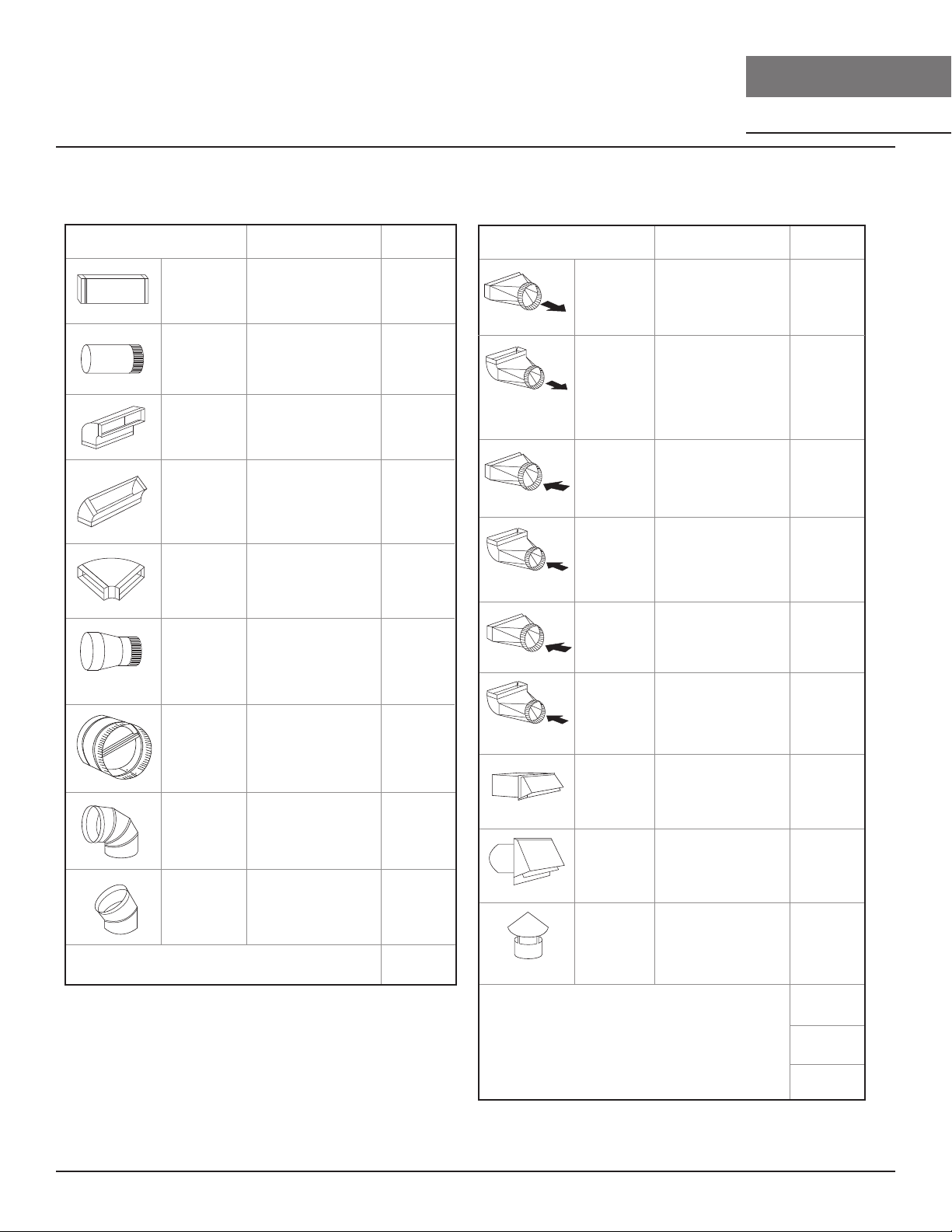
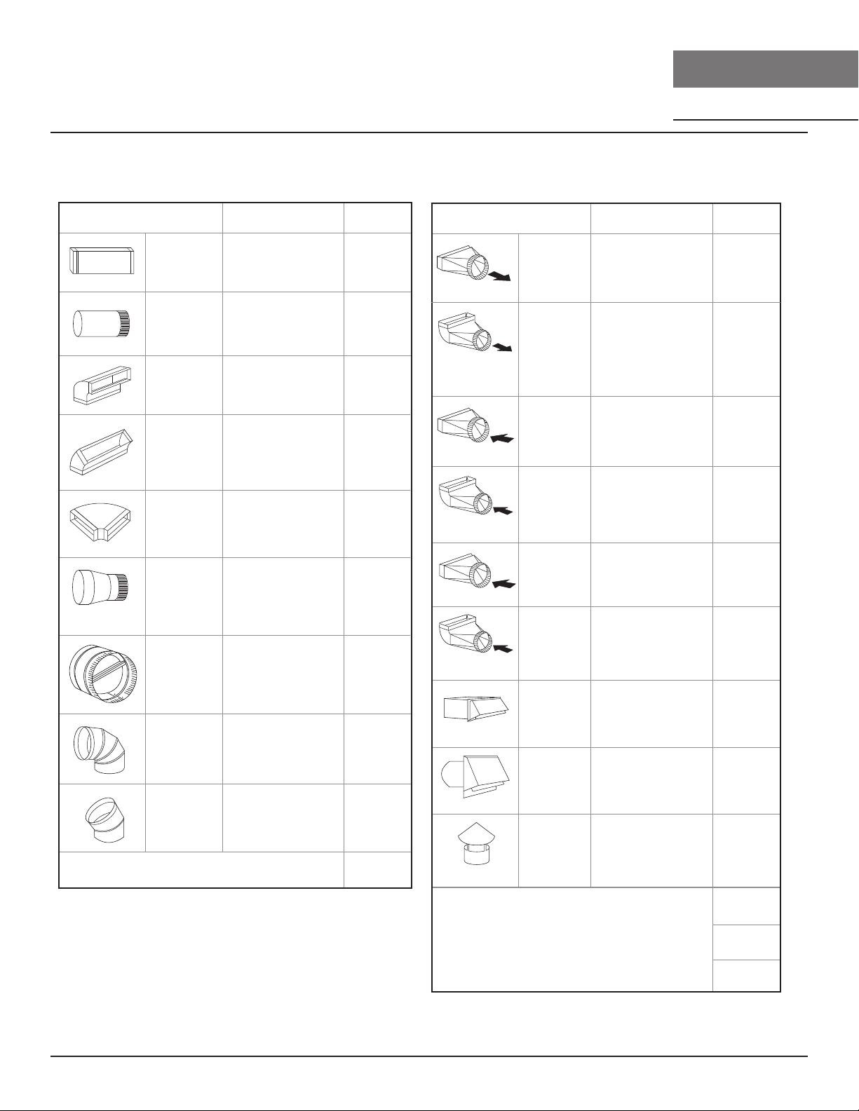
Duct pieces
To t a l
Equivalent number
length x used =
3- 1/ 4” x 10”
Rect.,
straight
1 Ft. x ( ) =
Ft.
3- 1/ 4” x 10”
Rect. to
6” round
transition
5 Ft. x ( ) =
Ft.
3- 1/ 4” x 10”
Rect. to
6” round
transition
90
0
elbow
20 Ft. x ( ) =
Ft.
6”, 7”, 8”, 10”
Round,
90
0
15 Ft.
x ( ) =
Ft.
6”, 7”, 8”, 10”
Round,
45
0
9 Ft. x ( ) =
Ft.
Ft.
6”, 7”, 8”, 10”
Round,
straight
1 Ft. x ( ) =
Ft.
Subtotal column 1 =
Duct pieces
To t a l
Equivalent number
length x used =
6”, 7”, 8”, 10”
Round, wall
cap with
damper
30 Ft. x ( ) =
Ft.
Ft.
Ft.
Ft.
6”, 7”, 8”, 10”
Round
roof cap
30 Ft. x ( ) =
Ft.
Subtotal column 2 =
Subtotal column 1 =
Total ductwork =
Maximum Duct Length: For satisfactory air movement,
the total duct length
should not exceed 150 equivalent feet.
6” round to
3- 1/ 4” x 10”
rect.
transition
1 Ft. x ( ) =
Ft.
6” round to
3- 1/ 4” x 10”
rect.
transition
90
0
elbow
16 Ft. x ( ) =
Ft.
7” round to
3 1/ 4” x 10”
rect.
transition
8 Ft. x ( ) =
Ft.
7” round to
3- 1/ 4” x 10”
rect.
transition
90
0
elbow
23 Ft. x ( ) =
Ft.
elbow
elbow
7” to 6” or
8” to 7” Round
tapered
reducer
25 Ft. x ( ) =
Ft.
3- 1/ 4” x 10”
Rect. 90
0
elbow
15 Ft. x ( ) =
Ft.
3- 1/ 4” x 10”
Rect. 45
0
elbow
9 Ft. x ( ) =
Ft.
3- 1/ 4” x 10”
Rect. 90
0
flat elbow
24 Ft. x ( ) =
Ft.
3- 1/ 4” x 10”
Rect.
wall cap
with damper
30 Ft. x ( ) =
Ft.
Ft. x ( ) =
Ft.
15
6”, 7“, 8”
Round
in-line
damper
Ducting Calculation Sheet
9
Pisa Use, Care, and Installation Guide
ZEPHYRONLINE.COM
Installation Instructions
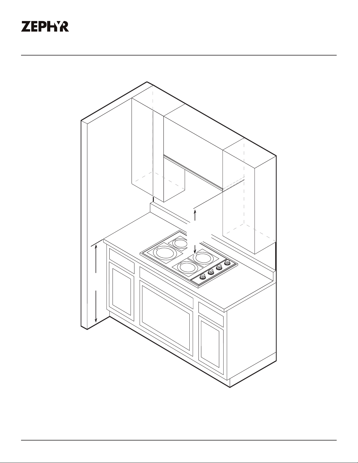
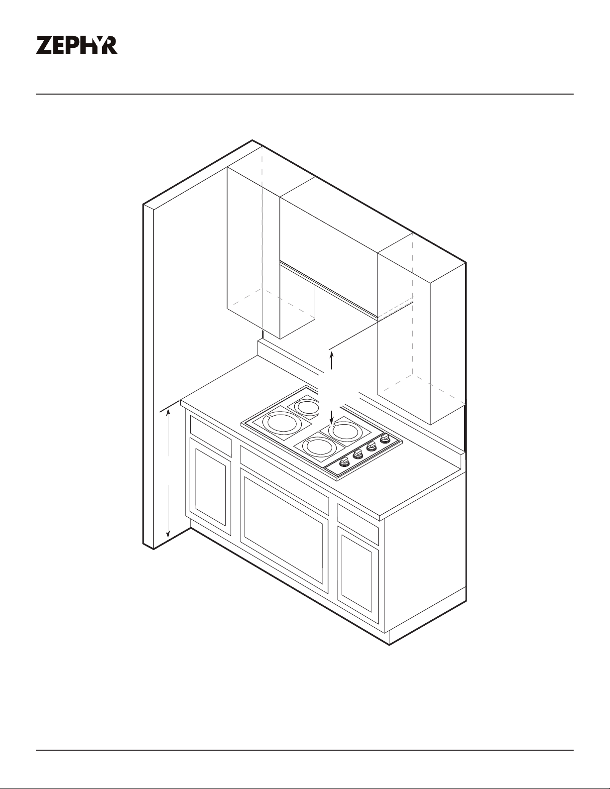
Mounting Height, Clearance, & Ducting
3
6”
20” min.
24” min.
32” max.
NOTE: The Pisa minimum mount height for electric cook tops is 20”, but is 24” for gas cook tops.

10
Pisa Use, Care, and Installation Guide
PISA
UNDERCABINET
CORE
Installation Instructions
Mounting Height, Clearance, & Ducting
A minimum of 6” round ducting must be used to maintain maximum air flow eciency.
Always use rigid type metal ducts only. Flexible ducts could restrict air flow by up to 50%.
Also use the ducting calculation sheet (on page 8) to compute total available duct run when using
elbows, transitions and caps.
ALWAYS, when possible, reduce the number or transitions and turns. If long duct run is required,
increase duct size.
If turns or transitions are required; install as far away from hood duct output and as far apart,
between the two as possible.
Minimum mount height between range top to hood bottom should be no less than 20” for electric
cook tops and 24” for gas cook tops.
Maximum mount height should be no higher than 32”.
It is important to install the hood at the proper mounting height. Hoods mounted too low could result
in heat damage and fire hazard; while hoods mounted too high will be hard to reach and will lose its
performance and eciency.
If available, also refer range manufacturer’s height clearance requirements and recommended hood
mounting height above range. Always check your local codes for any dierences.
For shipment and installation damages:
Ź Please fully inspect unit for damage before installation.
Ź If the unit is damaged in shipment, return the unit to the store in which it was bought for repair or
replacement.
Ź If the unit is damaged by the customer, repair or replacement is the responsibility of the customer.
Ź If the unit is damaged by the installer (if other than the customer), repair of replacement must be
made by arrangement between customer and installer.
11
Pisa Use, Care, and Installation Guide
ZEPHYRONLINE.COM
Installation Instructions
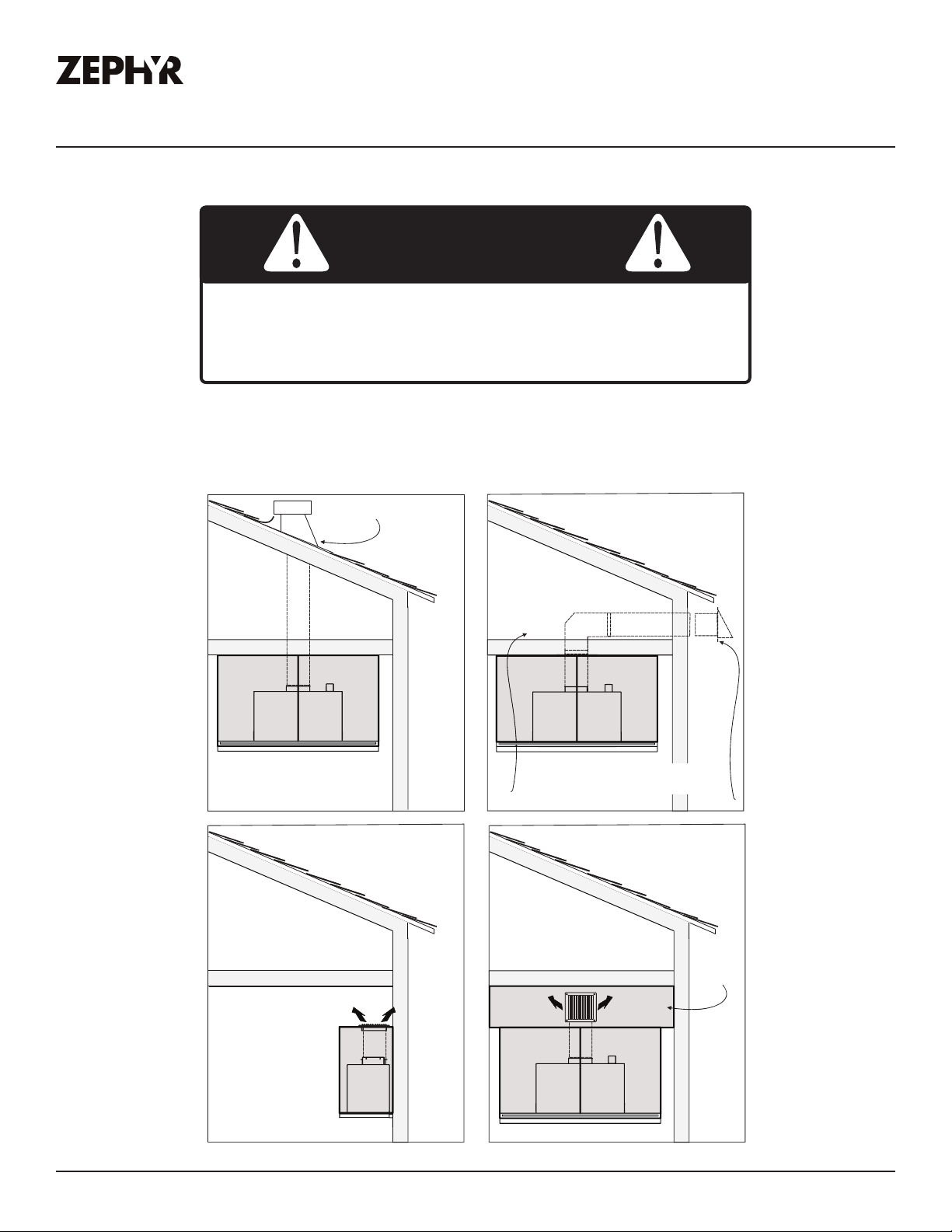
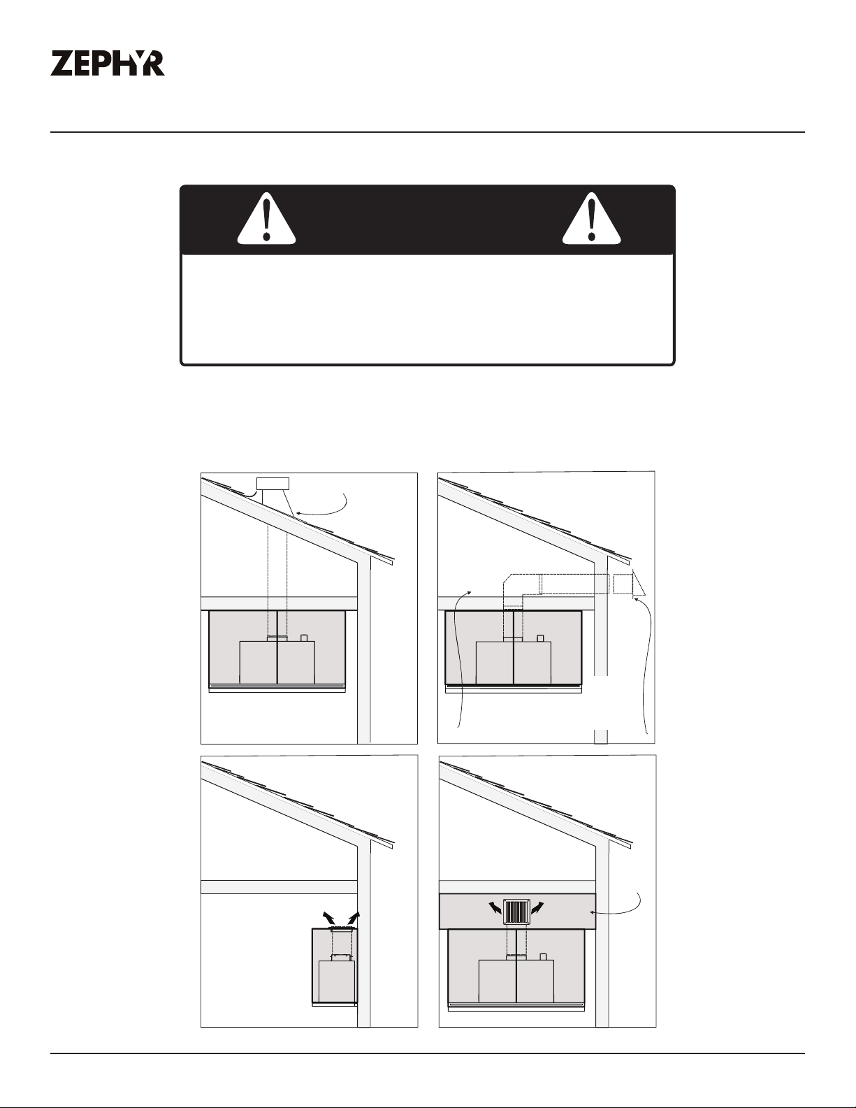
Ducting Options
Ź Use single wall rigid metal ductwork only.
Ź Fasten all connections with sheet metal screws and tape all joints w/ certified Silver Tape or Duct
Tape.
Fire Hazard: NEVER exhaust air or terminate ductwork into
spaces between walls, crawl spaces, ceilings, attics, or garages.
All exhaust must be ducted to the outside, unless using the
recirculating option.
WARNING
roof pitch w/
ůćp
ħr
p
ű
ű
12
Pisa Use, Care, and Installation Guide
PISA
UNDERCABINET
CORE
Installation Instructions
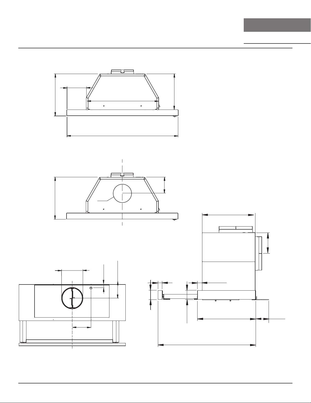
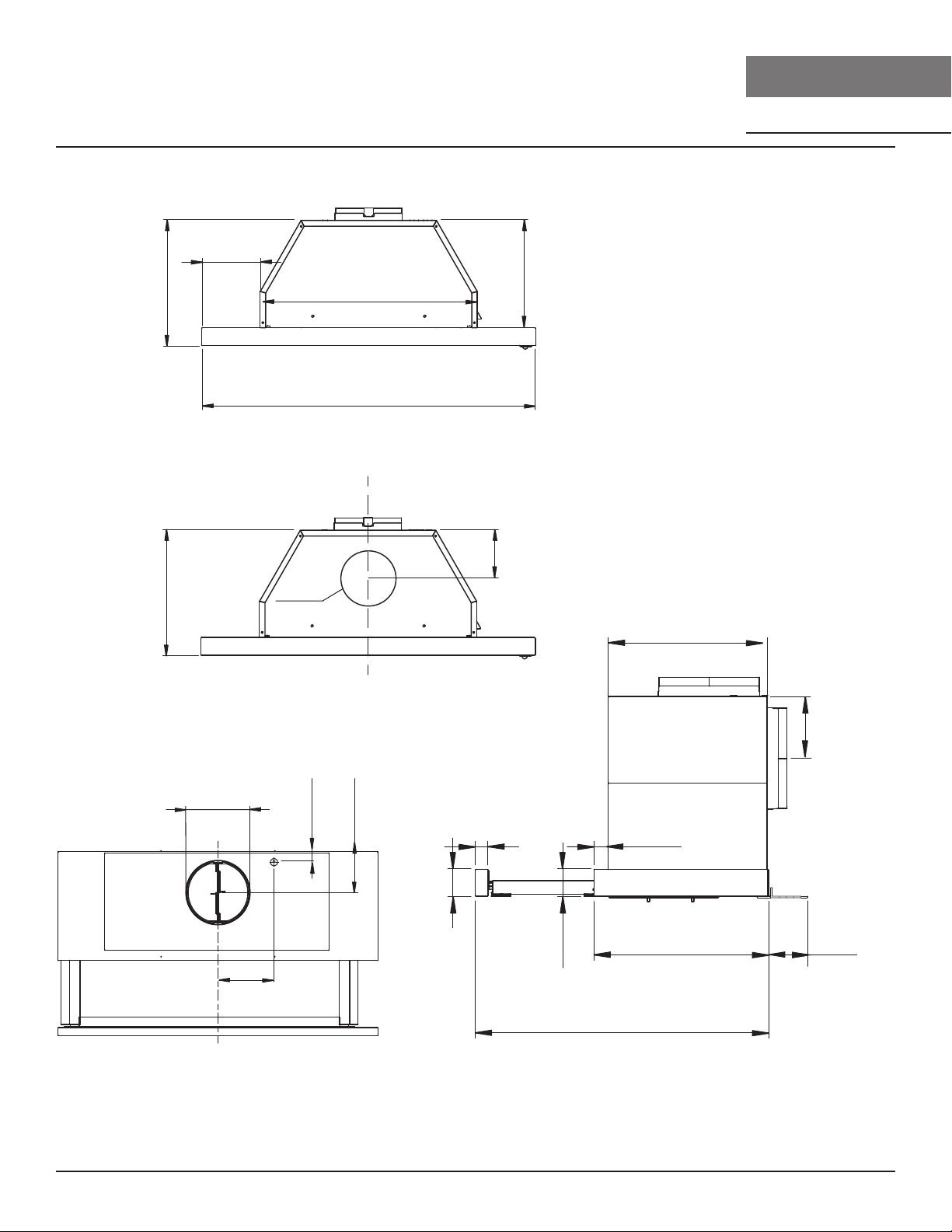
Ů
2-3/16” (24”)
5-3/16” (30”)
8-3/16” (36”)
11-1/4”
19-9/16”
9-9/16”
23-7/8” (24”), 29-7/8” (30”), 35-7/8” (36”)
FRONT
11-1/4”
Ø6”
3-7/16”
C/L
BACK
Ø6”
C/L
3/4”
3-7/16”
4-15/16”
TOP SIDE
3-7/16”
9-7/8”
1-1/8”
13/16”
1-1/2”
1-11/16”
3/8”-
2-1/4”*
*adjustable
rear filler
panel
11-1/8”
11-15/16” to 18-3/4”
Closed Open
13
Pisa Use, Care, and Installation Guide
ZEPHYRONLINE.COM
Installation Instructions
Electrical Supply
Electrical wiring must be done by qualified person(s) in
accordance with all applicable codes and standards. Turn o
electrical power at service entrance before wiring.
WARNING
For personal safety, remove house fuse or open circuit breaker before beginning installation. Do not
use extension cord or adapter plug with this appliance.
Follow national electrical codes or prevailing local codes and ordinances.
This appliance requires a 120V 60Hz electrical supply, and connected to an individual, properly
grounded branch circuit, protected by a 15 or 20 ampere circuit breaker or time delay fuse. Wiring
must be 2 wire w/ ground. Please also refer to the Electrical Diagram labeled on product.
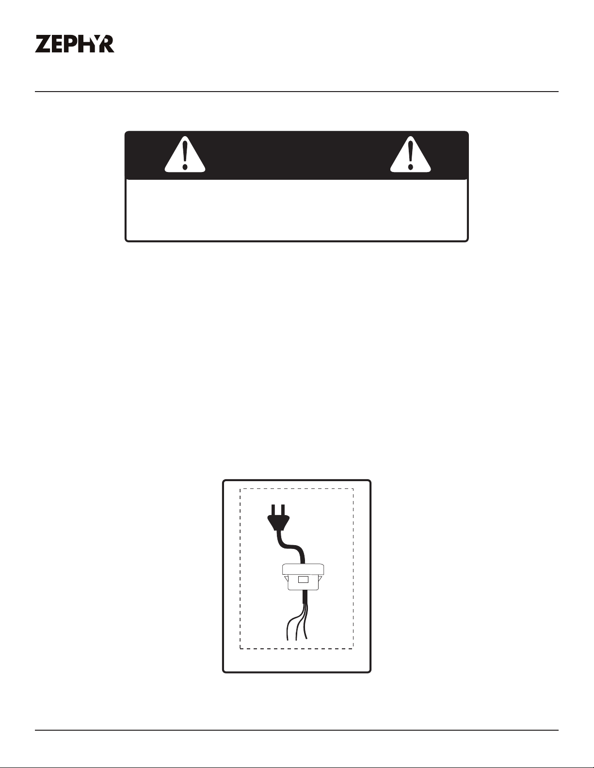
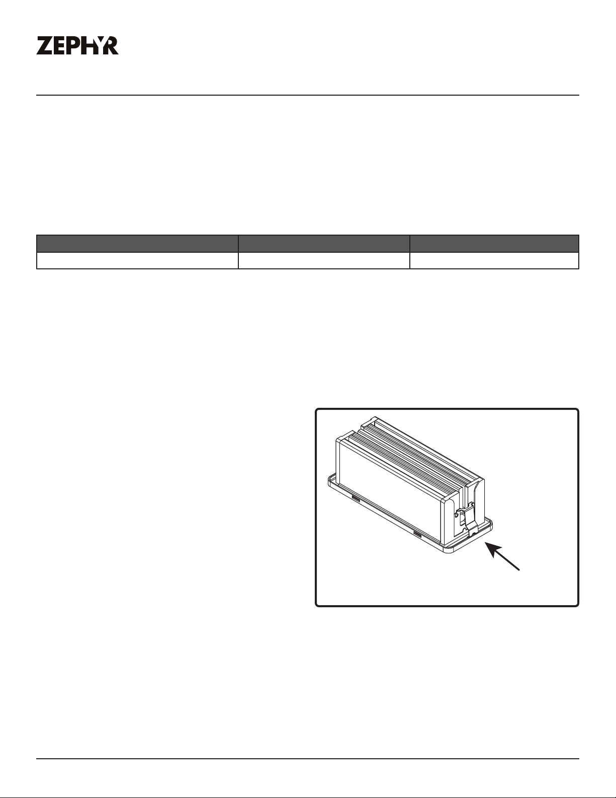
Cable Lock
A cable locking connector (not supplied) might be required by local codes. Check with local
requirements and codes, purchase and install appropriate connector if necessary. (FIG. A)
FIG. A
Cable Lock

14
Pisa Use, Care, and Installation Guide
PISA
UNDERCABINET
CORE
Installation Instructions
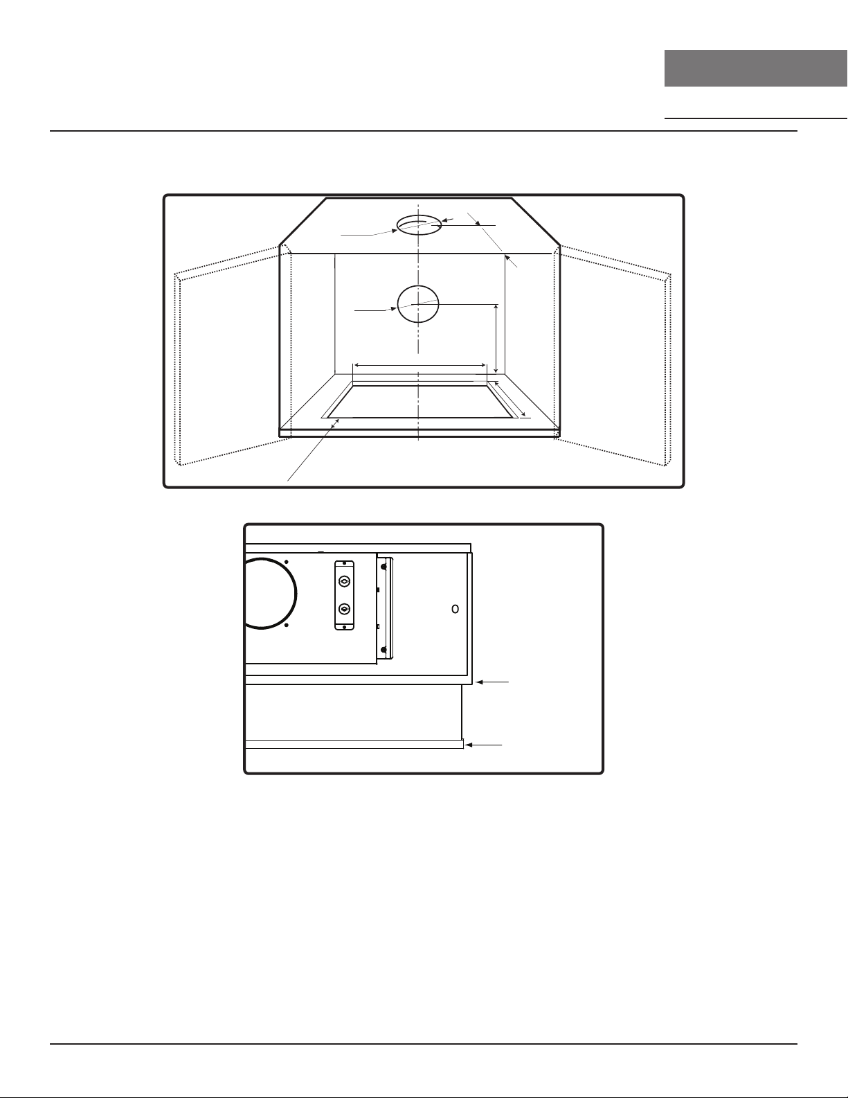
Preparing the Cabinet
1. Determine and mark center line on wall and cabinet bottom with a pencil.
2. If the cabinet bottom is recessed, wood blocking must be installed to ensure proper alignment of
the hood with the cabinet bottom. Wood blocking should be flush within cabinet bottom.
3. Follow the dimensions in FIG. B and cut-out the bottom of your cabinet to create an opening for
the hood to fit through. For frameless cabinet measure 1-15/16” from the front of cabinet door. For
framed cabinet measure 1-15/16” from front of cabinet bottom.
FIG. B
7”
7-3/4”
7”
*6-3/16”
*11-1/2”
10-1/8”
19-7/8”
C/L
1-15/16”
*Dimension used for rear ducting option
front edge
glass handle
FIG. C
15
Pisa Use, Care, and Installation Guide
ZEPHYRONLINE.COM
Installation Instructions
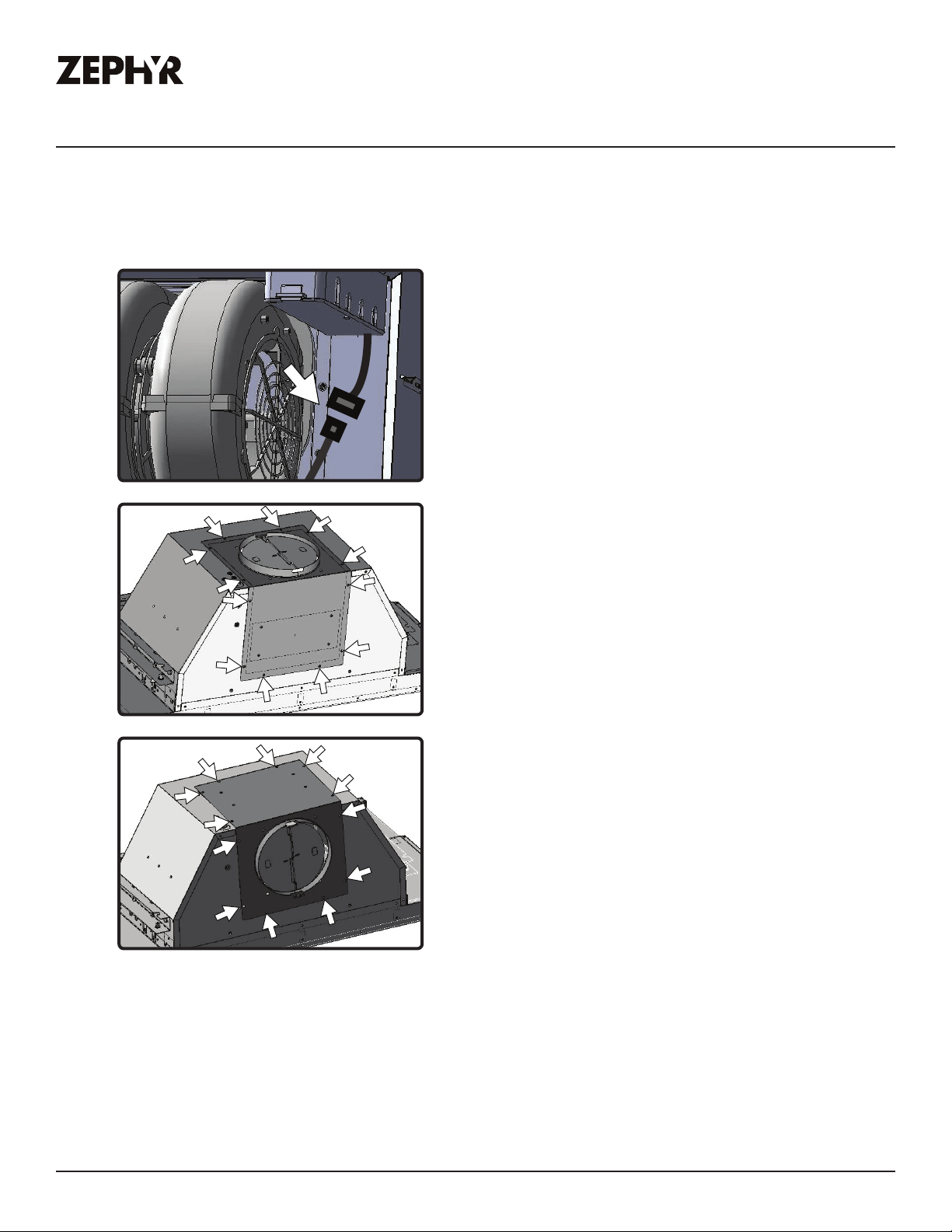
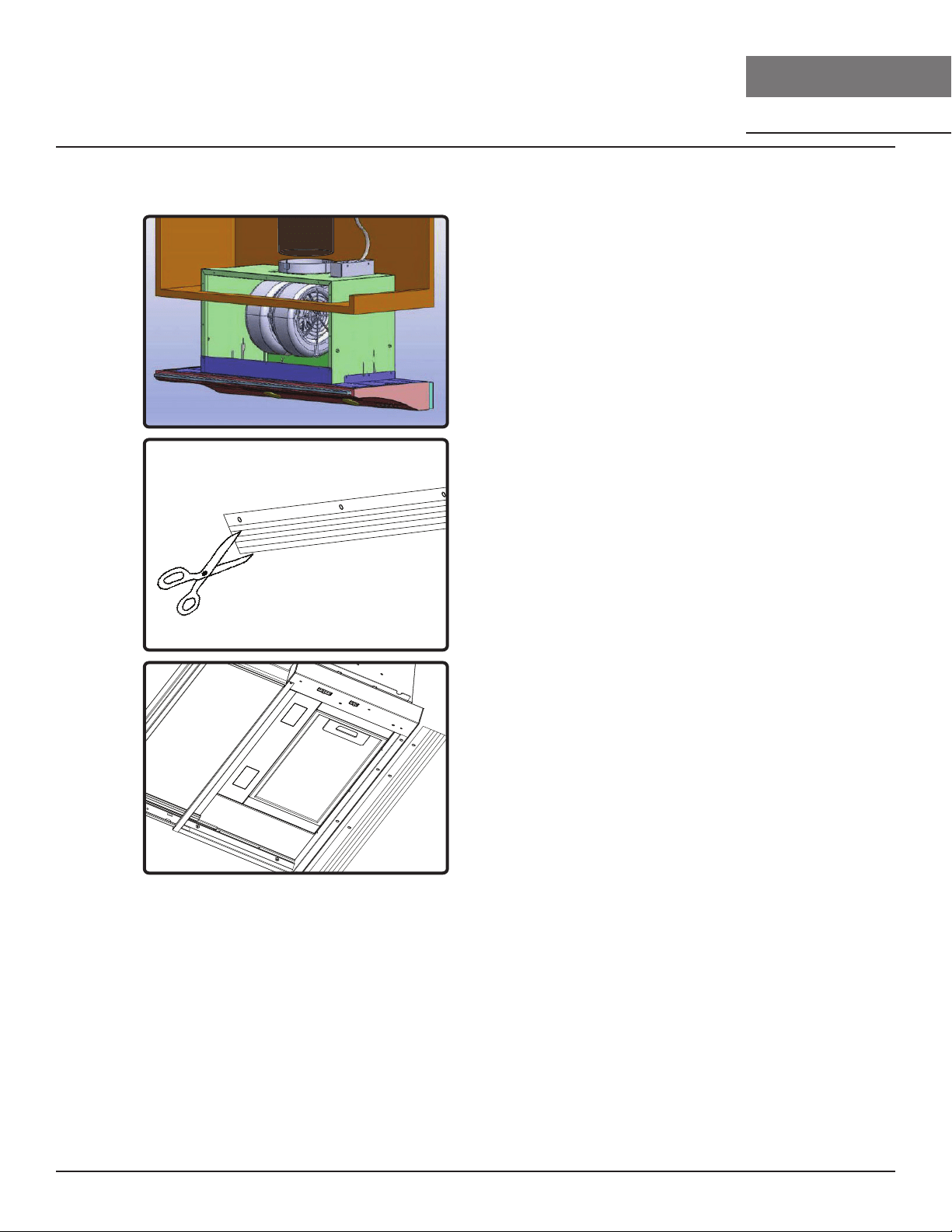
Horizontal Ducting Conversion
These steps below convert 6” round vertical ducting to horizontal ducting. If you plan on having
vertical ducting, please skip these steps.
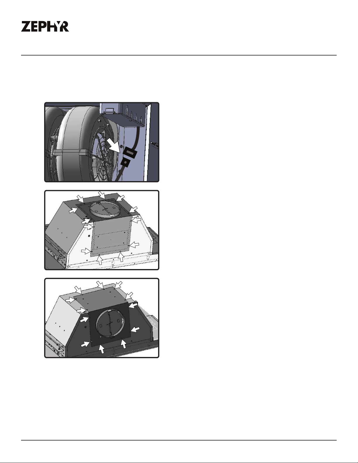
1. Remove aluminum mesh filter. From
inside the hood, disconnect blower plug
located toward the right side interior of
hood body.
2. Remove (6) screws from top of hood and
(6) screws from back of hood attaching
blower plate to hood body.
3. Remove blower and blower plate from
hood body and reposition blower to
hood body so blower collar protrudes
from back of hood body. Re-install
blower plate to hood body using the (12)
screws previously removed from step 2.
Re-connect blower plug.
16
Pisa Use, Care, and Installation Guide
PISA
UNDERCABINET
CORE
Installation Instructions
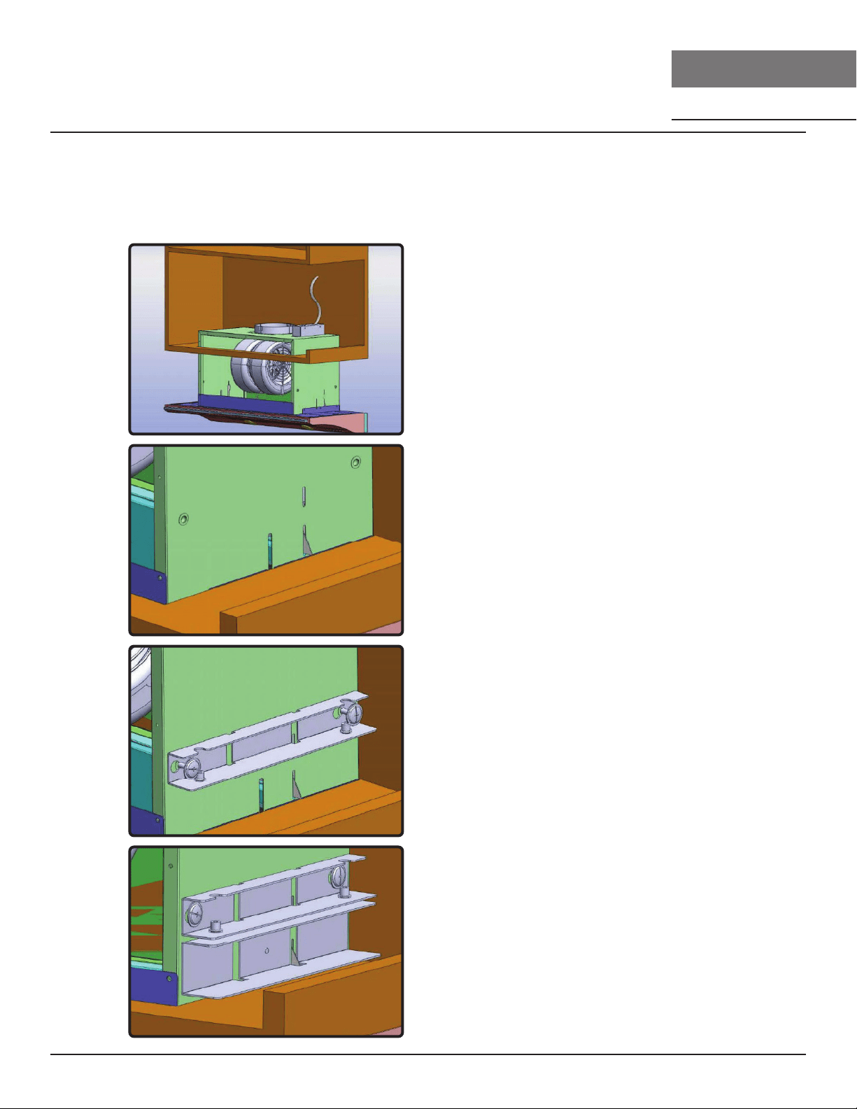
Mounting the Hood
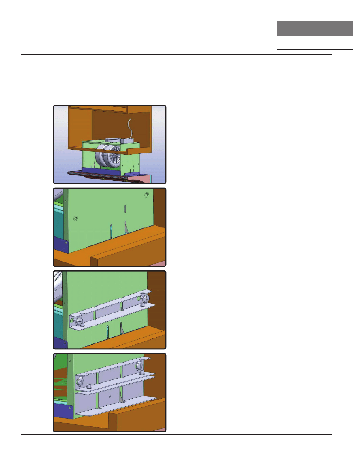
1. Prepare electrical wiring and ducting in cabinet. Location of the junction box and blower outlet
can be found on page 12. NOTE: Only 24” models have upper and lower brackets.
2. Open cabinet doors. Lift range hood
and slide it through the opening located
in the bottom of the cabinet. Make sure
opening matches the dimensions from
FIG. B.
3. There are spring clips located on the
left and right sides of the hood body
which will temporarily hold the hood in
place. If installing a 30” or 36” model,
skip to step 8. If installing a 24” model,
continue.
4. 24” Models Only. Secure upper brackets
to left and right sides of hood body by
using (2) 3/16 x 3/8” screws for each
bracket. Make sure the (2) captive nut
screws holes on the bracket are facing
downward.
5. 24” Models Only. Place lower installation
brackets under upper installation
brackets located on left and right sides
of hood body. The wider portion of the
lower installation bracket should be at
the bottom.

17
Pisa Use, Care, and Installation Guide
ZEPHYRONLINE.COM
Installation Instructions
Mounting the Hood
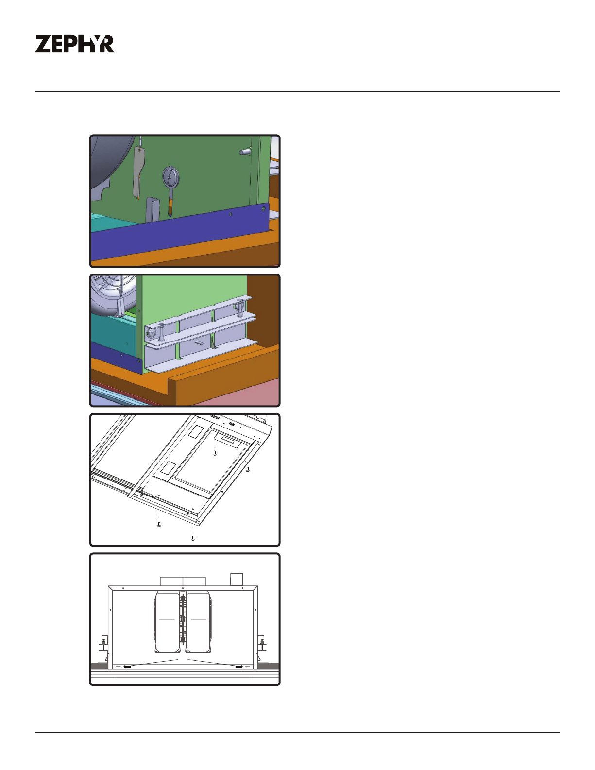
6. 24” Models Only. From inside the hood,
secure (1) M4x8 screw into each lower
installation bracket. The position of this
screw is adjustable to accommodate
various cabinet bottom thicknesses.
7. 24” Models Only. Install (2) 3/16x40
screws into the captive nuts of each
upper installation bracket. Tighten
screws to adjust the height of the range
hood until there is no gap between the
cabinet and front edge of the hood.
8. 30” & 36” Models Only. Secure hood
body to cabinet base by (4) M4 x 16mm
screws through the bottom of range
hood.
A
9. Secure (2) 1” wood screws (A) into the
screw holes on the left and right sides of
the filter opening.
18
Pisa Use, Care, and Installation Guide
PISA
UNDERCABINET
CORE
Installation Instructions
Mounting the Hood
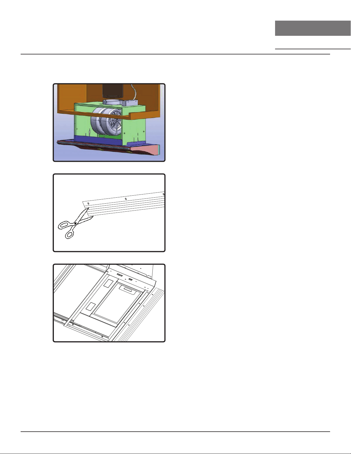
10. Place 6” round ducting over blower
collar and secure with aluminum
duct tape. If using hood in ductless
recirculating mode, refer to the Ductless
Recirculation section. Install electrical
wiring. Make sure no packing material
is inside hood. Power up hood check
for leaks around duct tape and verify all
functions.
11. Measure distance between back of
range hood and wall (if any) and cut
filler panel to the appropriate depth
using a utility knife or heavy-duty
scissors.
12. Install filler panel to bottom of hood by
(4) 3.5x10 screws for 24” model or (5)
3.5x10 screws for 30” and 36” model.
19
Pisa Use, Care, and Installation Guide
ZEPHYRONLINE.COM
Installation Instructions
Ductless Recirculation
Ductless recirculation is intended for applications where an exhaust duct work is not possible to be
installed. When converted, the hood functions as a recirculating hood rather than an exhaust hood.
Fumes and exhaust from cooking are drawn and filtered by a set of optional charcoal filters. The air is
then purified and re-circulated back within the home.
We recommend to ALWAYS exhaust air outside of the home by employing existing or installing new
duct work, if possible. The hood is most eective and ecient as an exhaust hood. Only when the
exhaust option is not possible should you recourse to converting the hood into a recirculating hood.
When converted to be a recirculating hood, a set of charcoal filters are required on top of its standard
Metal Filter set. Order according to its part number below. The standard mesh filters are intended to
capture residue from cooking, and the optional charcoal filters help to purify fumes exhausted from
cooking for recirculation.
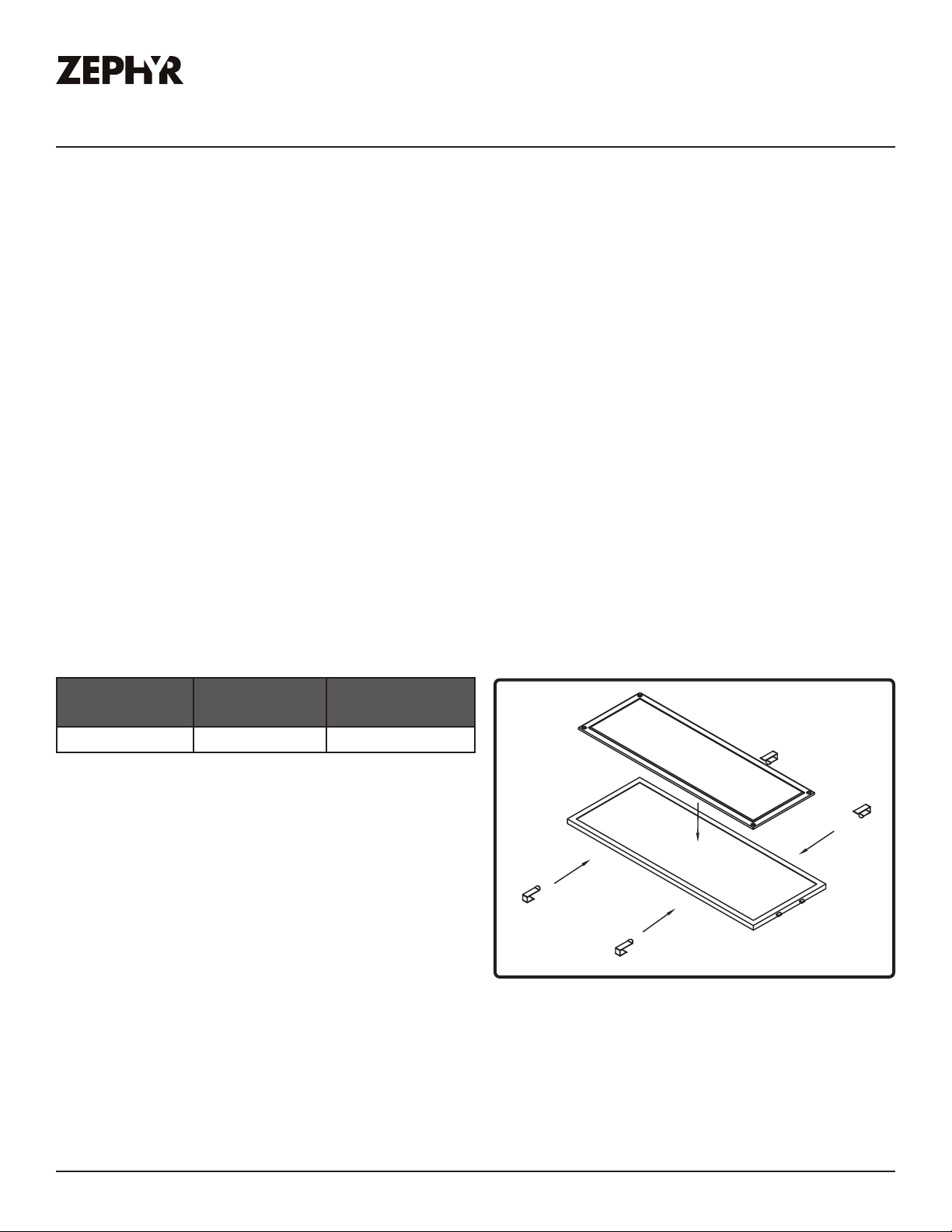
Recirculating Kit Installation (required if no ducting is used)
Kit includes the charcoal filters, brackets, and return air vent. For detailed installation instructions,
please refer to the manual included with the recirculating kit.
Hood Model Part Number Quantity to
Order
ZPI ZRC-00PI 1
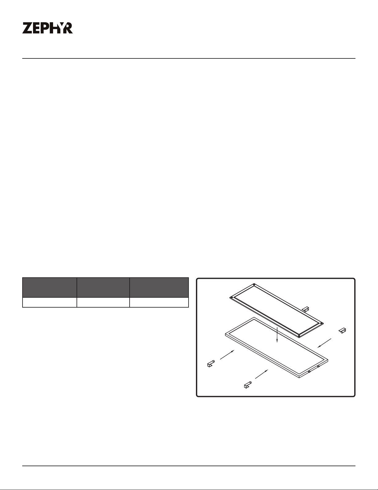
1. Purchase recirculating kit per the part number
above.
2. Remove aluminum mesh filter from hood and
place charcoal filter on top of the filter. Secure
charcoal filter by 4 C clips from ZRC-00PI, 2
C clips for each elongated side of the charcoal
filter, FIG. D.
3. Reinstall aluminum mesh filter.
FIG. D
20
Pisa Use, Care, and Installation Guide
PISA
UNDERCABINET
CORE
Installation Instructions
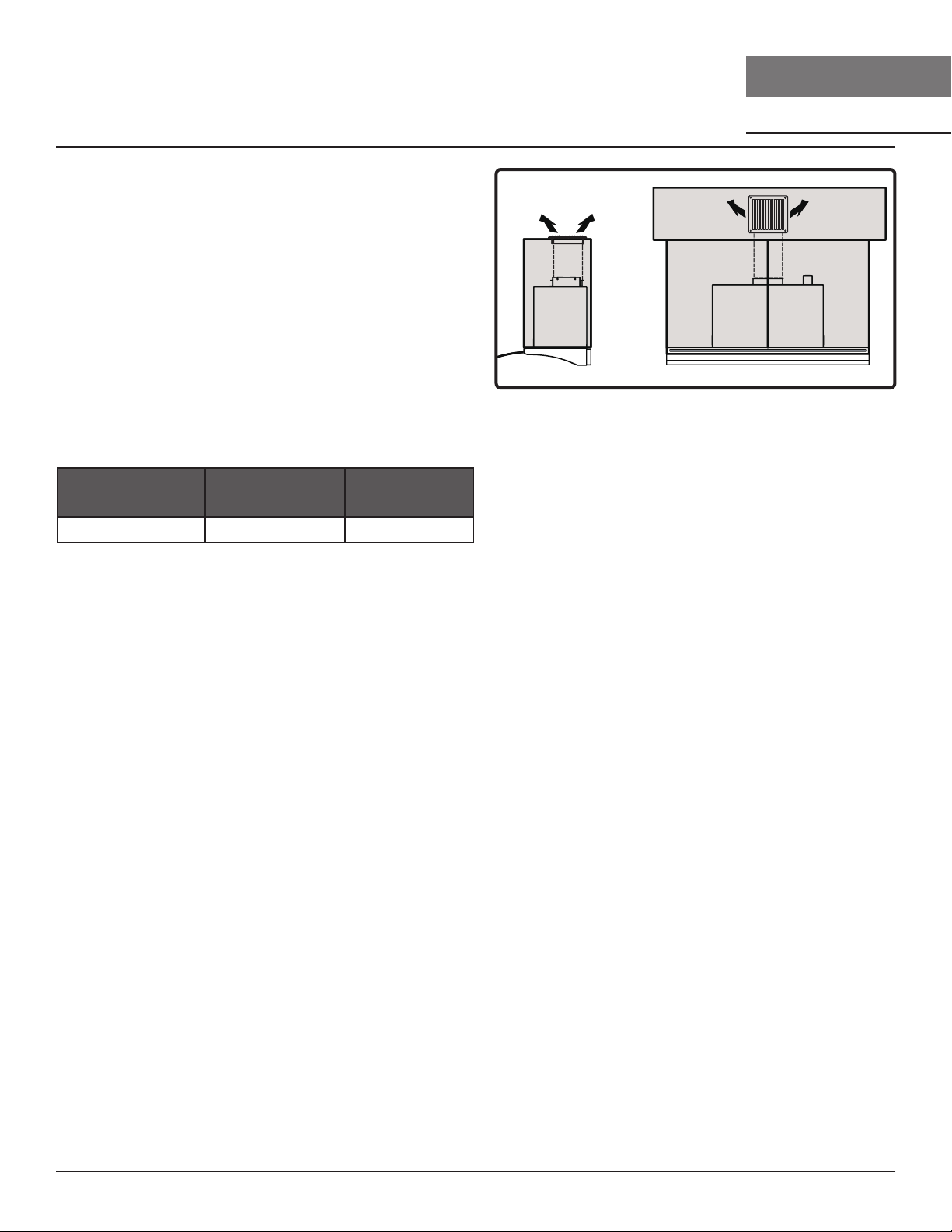
FIG. E
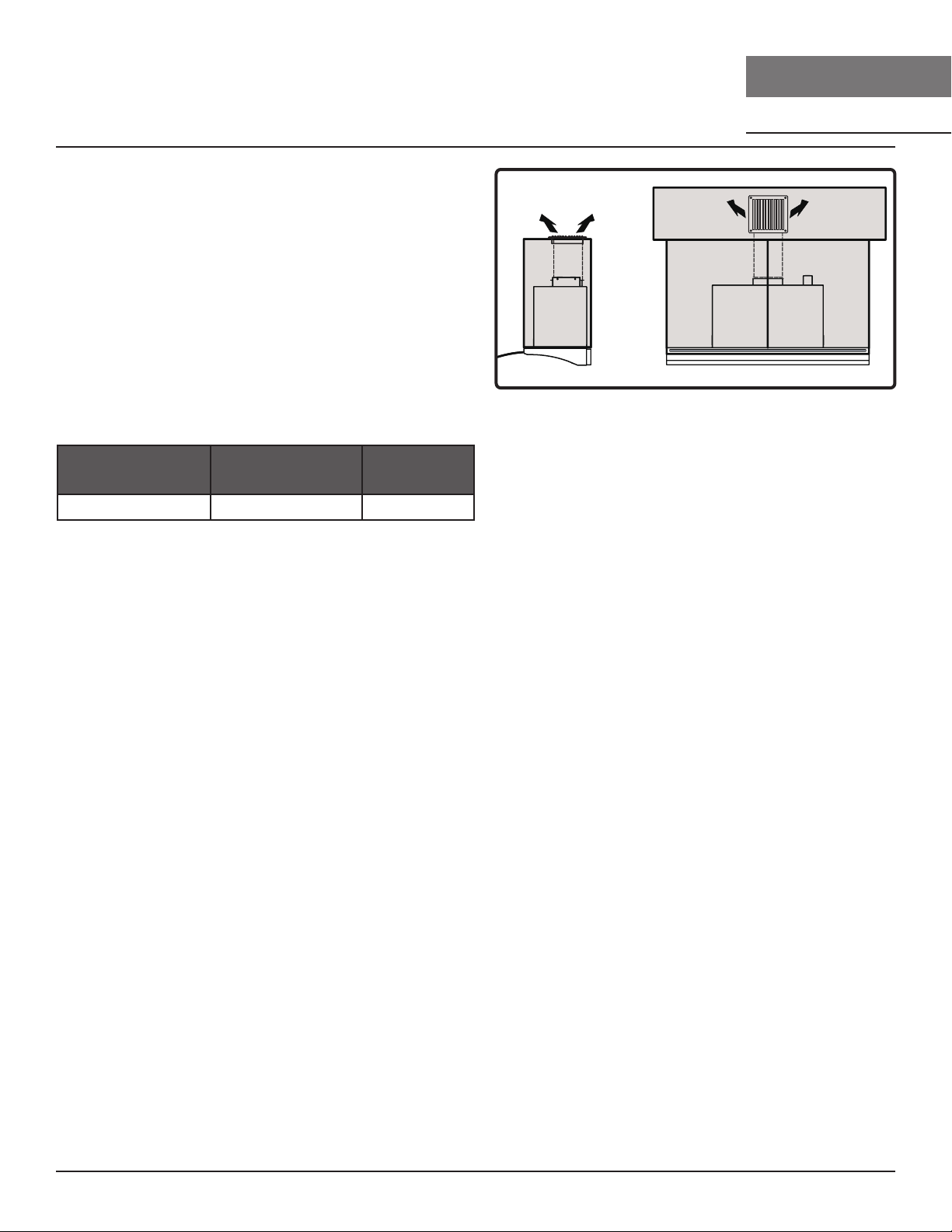
4. In order to recirculate the air properly, a return
air vent must be installed to allow recycled air
to be returned to the kitchen. FIG. E. Ducting
must be run from the blower to the return air
vent. The return air vent can be positioned on
top of the cabinet or in a sot/ceiling.
5. The charcoal filter must be replaced after
every 120 hours of use or approximately 3 to
4 months based on the average daily use of 1
hour of cooking time.
Charcoal Filter Replacements
Hood Model Part Number
Quantity to
Order
ZPI Z0F-C0PI 1
DO NOT WASH CHARCOAL FILTERS. Charcoal
filters may need to be changed more often
depending on cooking habits.
21
Pisa Use, Care, and Installation Guide
ZEPHYRONLINE.COM
Features & Controls
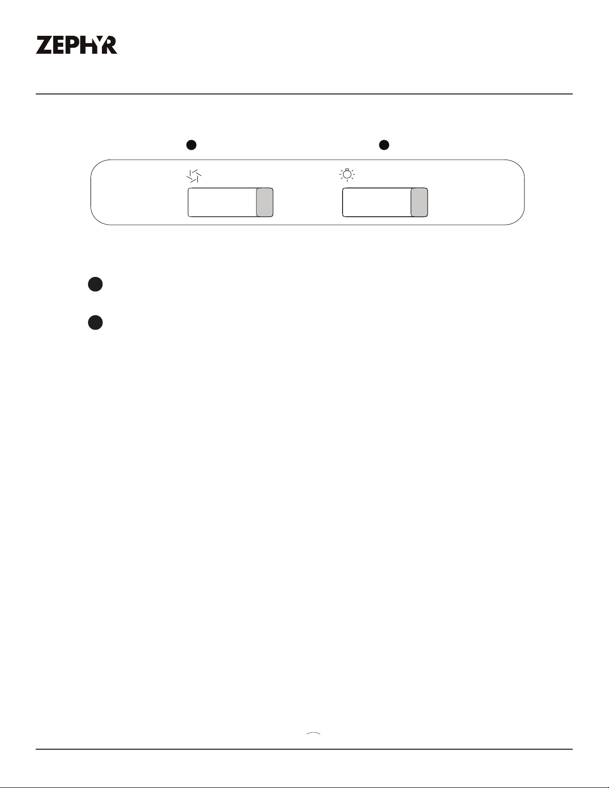
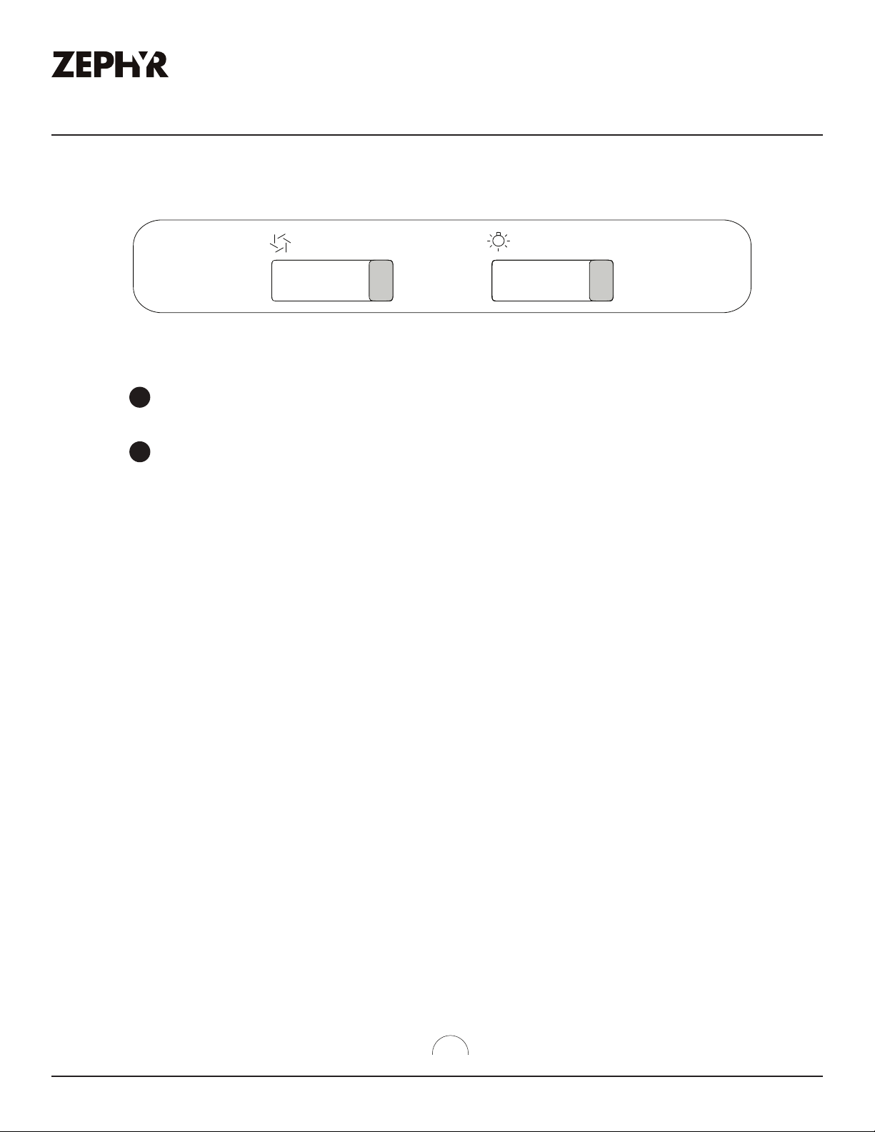
Slide Controls
0 I II III
Blower On/OŰ
1
Űħħ
2
0 I II
BLOWER ON/OFF/SPEED SELECTION
řŰĕĕĘ
LIGHTS OFF/DIM/BRIGHT
řŰĕĕĘ
1
2
Ű
Ę
Ę
NOTE:

22
Pisa Use, Care, and Installation Guide
PISA
UNDERCABINET
CORE
Hood & Filter Cleaning
Surface Maintenance
Ź Do not use corrosive detergents, abrasive detergents or oven cleaners.
Ź Do not use any product containing chlorine bleach or any product containing chloride.
Ź Do not use steel wool or abrasive scrubbing pads which will scratch and damage surface.
Cleaning Stainless Steel
Clean periodically with warm soapy water and clean cotton cloth or micro fiber cloth. Always rub
in the direction of the stainless steel grain. To remove heavier grease build up use a liquid degreaser
detergent.
After cleaning use a non-abrasive stainless steel polish/cleaners, to polish and bu out the stainless
luster and grain. Always scrub lightly, with clean cotton cloth or micro fiber cloth and bu in the
direction of the stainless steel grain.
Aluminum Mesh Filters
The aluminum mesh filters installed by the factory are intended to filter out residue and grease from
cooking. They need not be replaced on a regular basis but are required to be kept clean.
Remove and clean by hand or in dishwasher using a non-phosphate detergent. Discoloration of the
filter may occur if using phosphate detergents, or as a result of local water conditions - but this will
not aect filter performance. This discoloration is not covered by the warranty. Spray degreasing
detergent and leave to soak if heavily soiled.
Dry filters and re-install before using hood.
Maintenance
23
Pisa Use, Care, and Installation Guide
ZEPHYRONLINE.COM
Maintenance
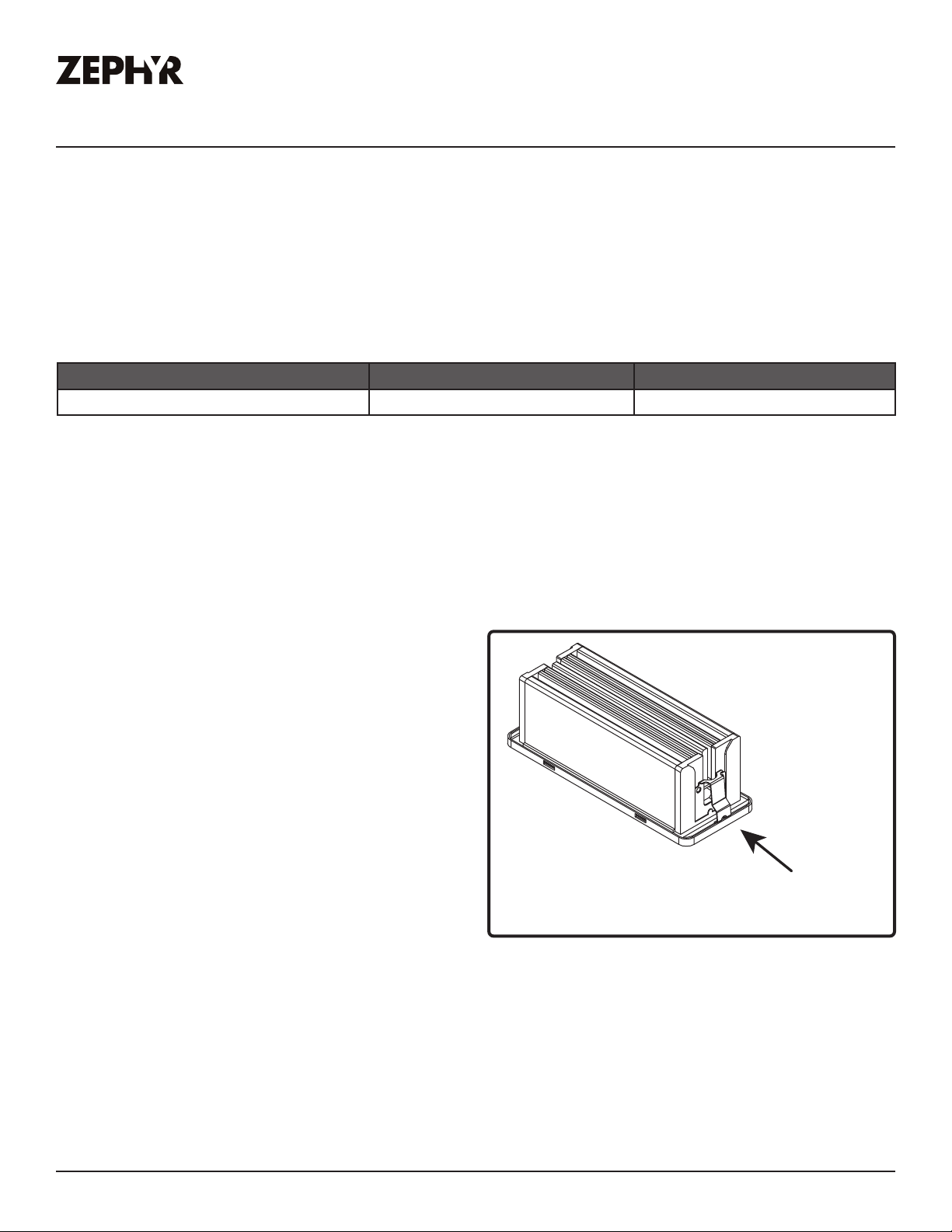
Removing Aluminum Mesh Filters
1. Push in filter latch.
2. Tilt filter down and remove from hood.
Replacing Aluminum Mesh Filters
Hood Model Part Number Quantity to Order
ZPI 50200054 1
To order parts, visit us online at http://store.zephyronline.com.
LumiLight LED
In the unlikely event that your LumiLight LED fails, please contact Zephyr to order replacement parts.
See the list of parts and accessories page for part numbers and contact information.
Push the clip
FIG. F
LED Removal (FIG. F):
1. Remove aluminum mesh filter.
2. Remove side panels if applicable, and remove
light panels by two screws.
3. Disconnect LED light quick connector.
4. Push in the two side clips on the ends of the
LED light.
5. Push LED light through the light panel opening.
24
Pisa Use, Care, and Installation Guide
PISA
UNDERCABINET
CORE
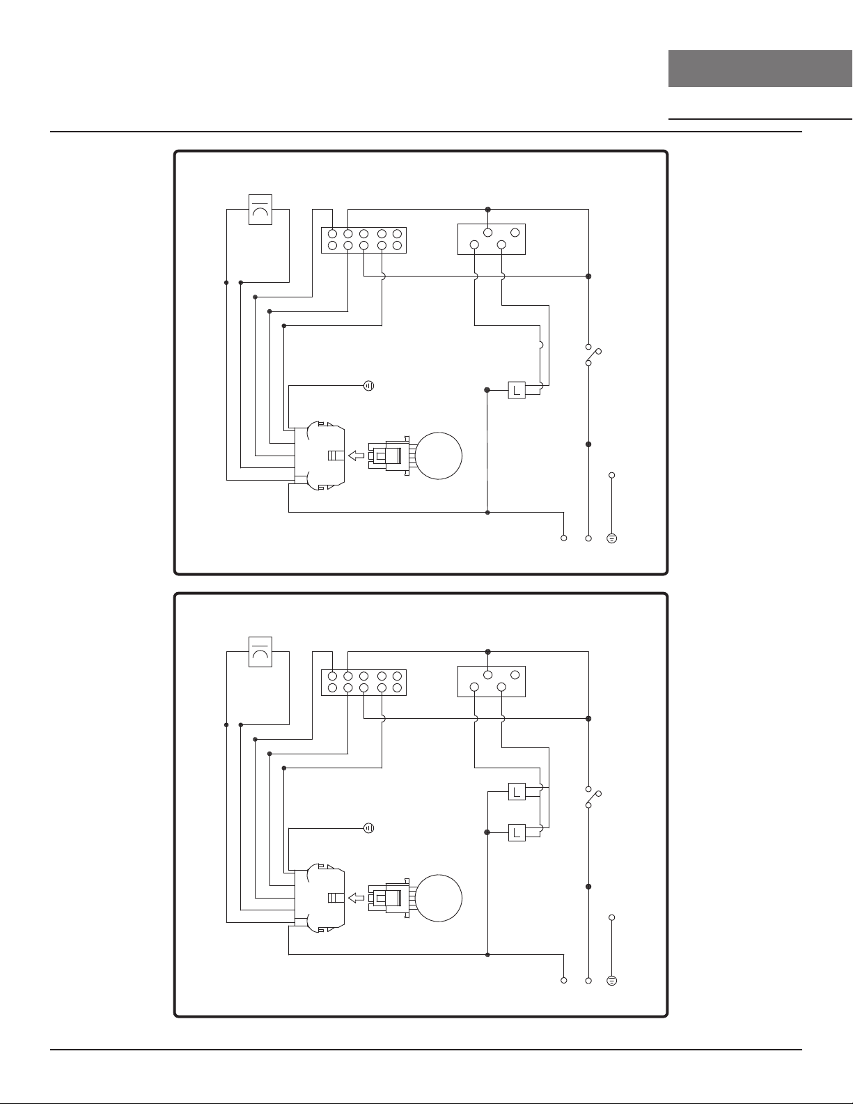
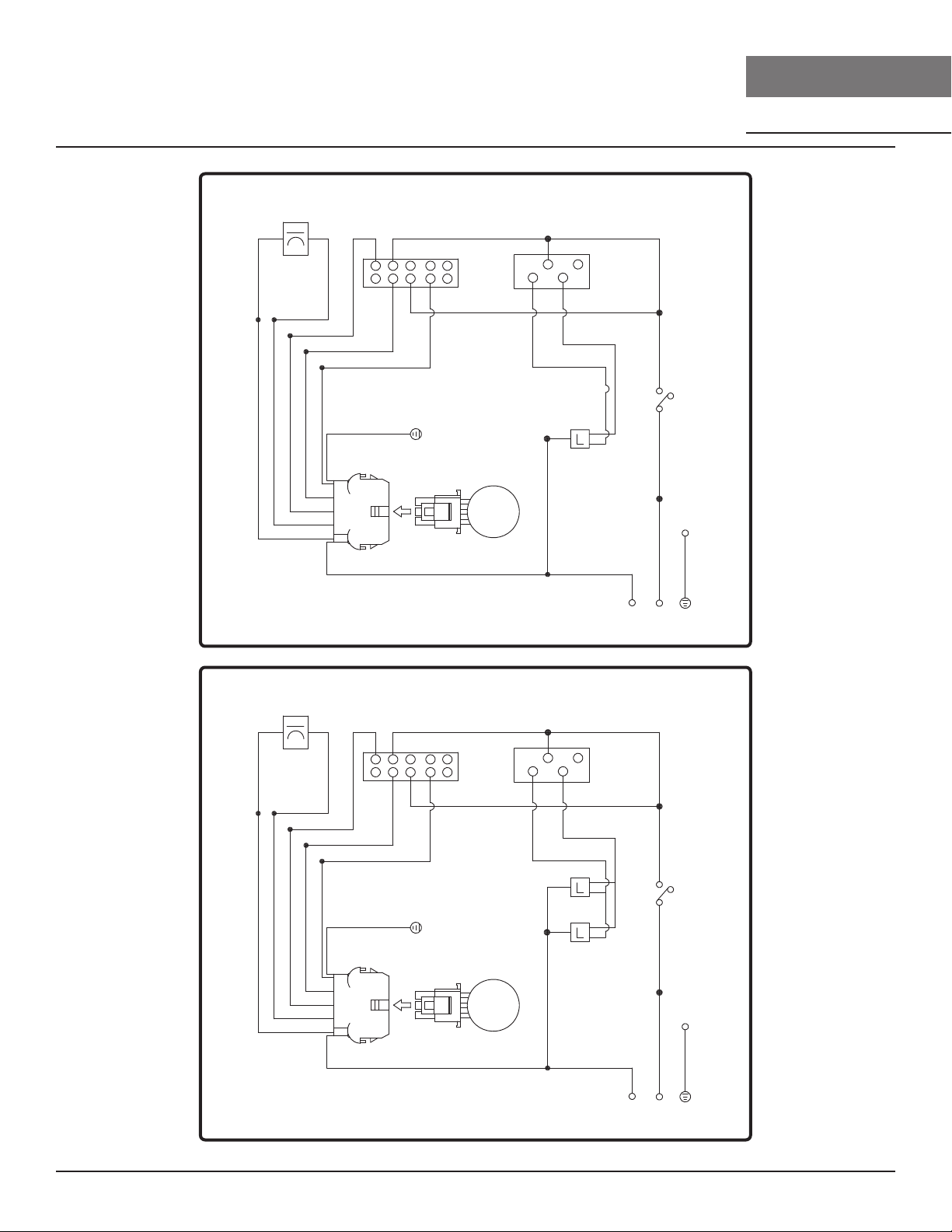
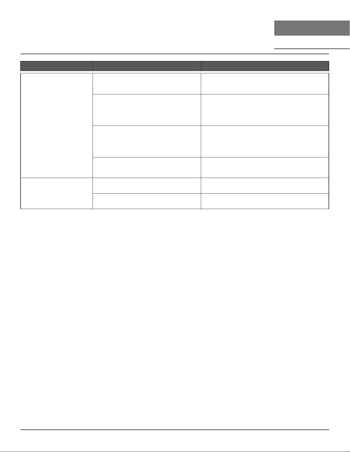
Wiring Diagram
ėśřųŚśřşřĕŜųśŢř
ĚŜřćĚŜş
ħ
ħ
ħ
RED
ħħ
RED
ħ
ėśřųŚśřşřĕŜųśŢř
ZPI-E24BS WIRING DIAGRAM
B/W
B/W
B/W
RED
BLACK
B/WB/WBLACK
GREEN
BODY
GREEN
BODY
MOTOR
RED
YELLOW
BLUE
BROWN
GREY
RED
YELLOW
BLUE
BROWN
GREY

25
Pisa Use, Care, and Installation Guide
ZEPHYRONLINE.COM
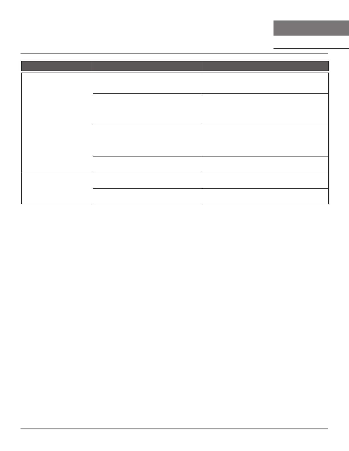
Troubleshooting
Possible Problem Possible Cause Solutions
After installation, the
unit doesn’t work.
The power source is not turned ON. Make sure the circuit breaker and the unit’s
power is ON.
The power line and the cable
locking connector is not connecting
properly.
Check the power connection with the unit is
connected properly.
The switch board or control board
wirings are disconnected.
Make sure the wirings at the switch board
and control board are connected properly.
The switch board or control board is
defective.
Change the switch board or control board.
The wires on control board are loose. Make sure the wires on the control board
are connected properly.
Light works, but blower
is not turning.
The blower wire is not connected. Make sure the blower wire is plugged into
the molex connector.
The thermally protected system
detects if the blower is too hot to
operate and shuts the blower down.
The blower will function properly after the
thermally protected system cool down.
Damaged capacitor. Change the capacitor.
The blower is defective, possibly
seized.
Change the blower.
The unit is vibrating. The blower is not secured in place. Tighten the blower in place.
Damaged blower wheel. Replace the blower.
The hood is not secured in place. Check the installation of the hood.
The unit is whistling. A filter is not in the correct position. Adjust the filters until the whistling stops.
The duct pipe connections are not
sealed or connected properly.
Check the duct pipe connections to be sure
all connections are sealed properly.
The blower is working,
but the LumiLight LEDs
are not.
The LumiLight LED connector is
disconnected.
Connect the LumiLight LED connector.
Defective LumiLight LED. Change the LumiLight LED.
The switch board or control board is
defective.
Change the switch board or control board.
LumiLight LEDs flicker
when changing speed
levels.
N/A This is a normal operation and the hood is
working correctly.
26
Pisa Use, Care, and Installation Guide
PISA
UNDERCABINET
CORE
Troubleshooting
The hood is not venting
out properly.
Using the wrong size of ducting. Change the ducting to the correct size.
The hood might be hanging to high
from the cook top.
Adjust the distance between the cook top
and the bottom of the hood within 20”
(electric cook tops) or 24” (gas cook tops)
and 32” range.
The wind from the opened windows
or opened doors in the surrounding
area are aecting the ventilation of
the hood.
Close all the windows and doors to eliminate
the outside wind flow.
Blockage in the duct opening or
ductwork.
Remove all the blocking from the duct work
or duct opening.
Filter is vibrating. Filter is loose. Adjust or change the filter.
Spring clip is broken on the filter. Change the spring clip.
Possible Problem Possible Cause Solutions
27
Pisa Use, Care, and Installation Guide
ZEPHYRONLINE.COM
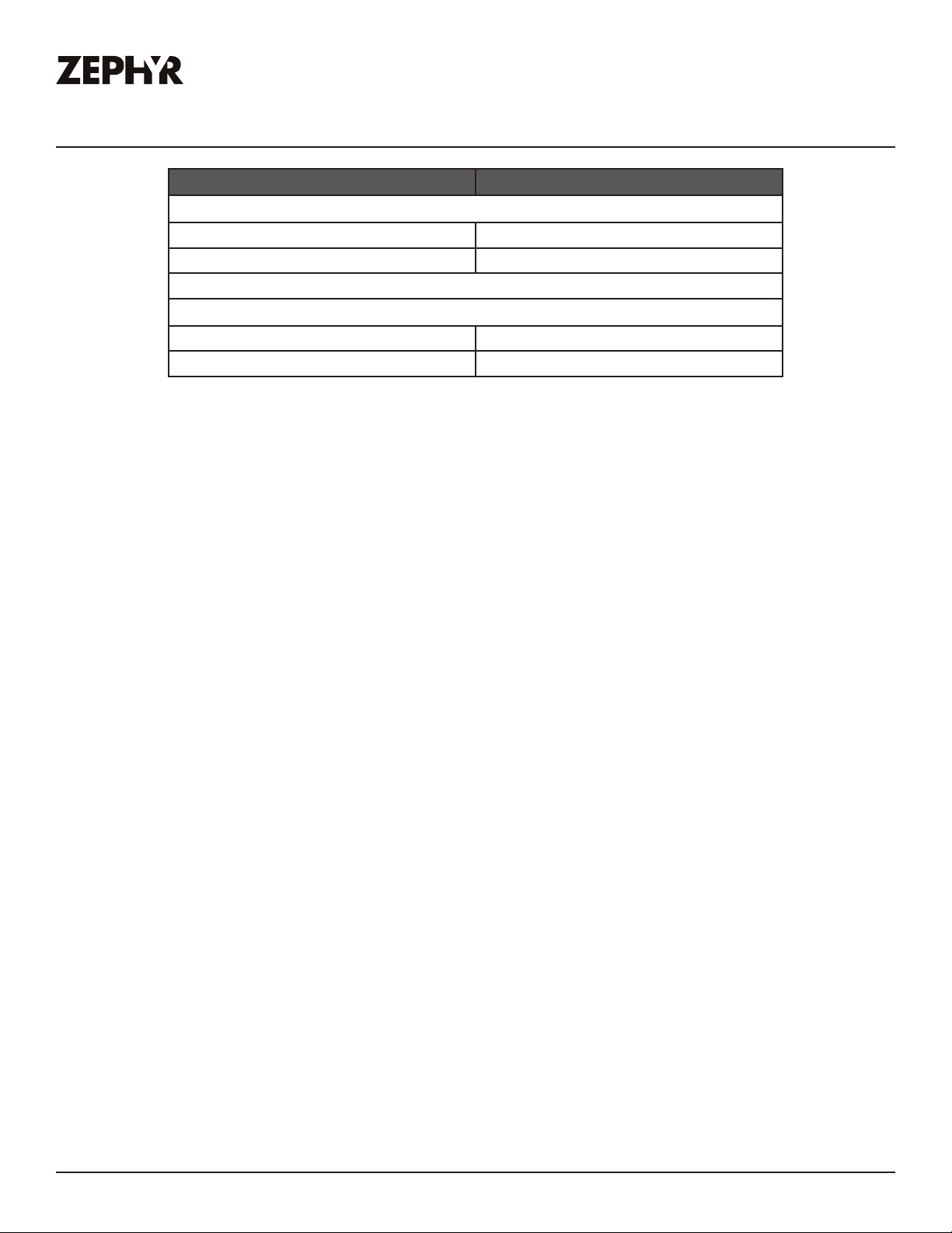
List of Parts & Accessories
Description Part Number
Replacement Parts
LumiLight LED, 6W Z0B0049
Aluminum Mesh Filter 50200054
Optional Accessories
Recirculating Kit ZRC-00PI
Replacement Charcoal Filter Z0F-C0PI
To order parts, visit us online at http://store.zephyronline.com.

28
Pisa Use, Care, and Installation Guide
PISA
UNDERCABINET
CORE
Notes

29
Pisa Use, Care, and Installation Guide
ZEPHYRONLINE.COM
Limited Warranty
MAY20.0401
Zephyr Ventilation, LLC (referred to herein as “we” or “us”) warrants to the original consumer purchaser (referred to herein
as “you” or “your”) of Zephyr products (the “Products”) that such Products will be free from defects in materials or
workmanship as follows:
Three Year Limited Warranty for Parts: For three years from the date of your original purchase of the Products, we will
provide, free of charge, Products or parts (including LED light bulbs, if applicable) to replace those that failed due to
manufacturing defects subject to the exclusions and limitations below. We may choose, in our sole discretion, to repair or
replace parts before we elect to replace the Products.
One Year Limited Warranty for Labor: For one
year from the date of your original purchase of the Products, we will
provide, free of charge, the labor cost associated with repairing the Products or parts to replace those that failed due to
manufacturing defects subject to the exclusions and limitations below. After the first year from the date of your original
purchase, you are responsible for all labor costs associated with this warranty.
Warranty Exclusions: This warranty covers only repair or replacement, at our option, of defective Products or parts and
does not cover any other costs related to the Products including but not limited to: (a) normal maintenance and service
required for the Products and consumable parts such as fluorescent, incandescent or halogen light bulbs, mesh and char-
coal filters and fuses; (b) any Products or
parts which have been subject to freight damage, misuse, negligence, accident,
faulty installation or installation contrary to recommended installation instructions, improper maintenance or repair (other
than by us); (c) commercial or government use of the Products or use otherwise inconsistent with its intended purpose; (d)
natural wear of the finish of the Products or wear caused by improper maintenance, use of corrosive and abrasive cleaning
products, pads, and oven cleaner products; (e) chips, dents or cracks caused by abuse or misuse of the Products; (f) service
trips to your home to teach you how to use the Products; (g) damage to the Products caused by accident, fire, floods, acts
of God; or (h) Custom installations or alterations that impact serviceability of the Products. If you are outside our service
area, additional charges may apply for shipping costs for
warranty repair at our designated service locations and for the
travel cost to have a service technician come to your home to repair, remove or reinstall the Products. After the first year
from the date of your original purchase, you are also responsible for all labor costs associated with this warranty. All Products
must be installed by a qualified professional installer to be eligible for warranty repairs or service.
Limitations of Warranty. OUR OBLIGATION TO REPAIR OR REPLACE, AT OUR OPTION, SHALL BE YOUR SOLE
AND EXCLUSIVE REMEDY UNDER THIS WARRANTY. WE SHALL NOT BE LIABLE FOR INCIDENTAL,
CONSEQUENTIAL OR SPECIAL DAMAGES ARISING OUT OF OR IN CONNECTION WITH THE USE OR
PERFORMANCE OF THE PRODUCTS. THE EXPRESS WARRANTIES IN THE PRECEDING SECTION ARE
EXCLUSIVE AND IN LIEU OF ALL OTHER EXPRE
SS WARRANTIES. WE HEREBY DISCLAIM AND EXCLUDE ALL
OTHER EXPRESS WARRANTIES FOR THE PRODUCTS, AND DISCLAIM AND EXCLUDE ALL WARRANTIES
IMPLIED BY LAW, INCLUDING THOSE OF MERCHANTABILITY AND FITNESS FOR A PARTICULAR PURPOSE.
Some states or provinces do not allow limitations on the duration of an implied warranty or the exclusion or limitation of
incidental or consequential damages, so the above limitations or exclusions may not apply to you. To the extent that
applicable law prohibits the exclusion of implied warranties, the duration of any applicable implied warranty is limited to the
same three-year and one-year periods described above if permitted by applicable law. Any oral or written description of the
Products is for the sole purpose of identifying the Products and shall not be construed as an express warr
anty. Prior to
using, implementing or permitting use of the Products, you shall determine the suitability of the Products for the intended
use, and you shall assume all risk and liability whatsoever in connection with such determination. We reserve the right to
use functionally equivalent refurbished or reconditioned parts or Products as warranty replacements or as part of warranty
service. This warranty is not transferable from the original purchaser and only applies to the consumer residence where the
Product was originally installed located in the United States and Canada. This warranty is not extended to resellers.
To Obtain Service Under Limited Warranty: To qualify for warranty service, you must: (a) notify us at the address or
telephone number stated below within 60 days of the discovery of the defect; (b) give the model number and serial
number;
and (c) describe the nature of any defect in the Product or part. At the time of the request for warranty service, you must
present evidence of your proof of purchase and proof of the original purchase date. If we determine that the warranty
exclusions listed above apply or if you fail to provide the necessary documentation to obtain service, you will be responsible
for all shipping, travel, labor and other costs related to the services. This warranty is not extended or restarted upon warranty
repair or replacements.
Please check our website for any additional Product information, www.zephyronline.com.
Zephyr Ventilation Service Department, 2277 Harbor Bay Parkway, Alameda, CA 94502 1-888-880-8368

30
Pisa Use, Care, and Installation Guide
PISA
UNDERCABINET
CORE
Product Registration
Congratulations on the purchase of your
Zephyr product! Please take a moment to
register your new Zephyr product at
www.zephyronline.com/registration
Zephyr Ventilation | 2277 Harbor Bay Pkwy. | Alameda, CA 94502 | 1.888.880.8368
Prompt registration helps in more ways
than one.
IT’S IMPORTANT
Ensures warranty coverage should you need
service.
Ownership verification for insurance purposes.
Notification of product changes or recalls.

WWW.ZEPHYRONLINE.COM
JAN21.0101
EN Use, Care, and Installation Guide
FR Guide d’utilisation, d’entretien et d’installation
Pisa
ZPI-E24BG, ZPI-E24BG290
ZPI-E24BW, ZPI-E24BW290
ZPI-E30BG, ZPI-E30BG290
ZPI-E30BW, ZPI-E30BW290
ZPI-E36BG, ZPI-E36BG290

2
Pisa Guide d’utilisation, d’entretien et d’installation
SOUSARMOIRE
CORE
PISA

3
Pisa Guide d’utilisation, d’entretien et d’installation
ZEPHYRONLINE.COM
Table des matières
Page
Consignes de sécurité ....................................................................... 4-6
Types d’avertissements de sécurité ..................................................... 4
Sécurité générale ...............................................................................4-5
Opération ........................................................................................... 6
Exigences électriques ......................................................................... 6
Déclaration d’interface de la Federal Communication Commission ... 6
Liste de matériel ..................................................................................7
Instructions d’installation ................................................................. 8-20
Feuille de calcul pour le conduit d’aération ......................................... 8
Hauteur de montage, dégagement et gaine .....................................9-10
Options de conduits ........................................................................... 11
Spécifications de la hotte ...................................................................12
Fourniture électrique ..........................................................................13
Raccord de câble ...............................................................................13
Préparation du cabinet .......................................................................14
Conversion de conduit horizontal .......................................................15
Montage de la hotte ........................................................................ 16-18
Recirculation sans conduit ...............................................................19-20
Fonctionnalités et commandes ........................................................... 21
Commandes à glissière ......................................................................21
Entretien .......................................................................................... 22-23
Nettoyage de la hotte et du filtre .....................................................22-23
LumiLight LED ................................................................................... 23
Schéma de câblage ............................................................................24
Dépannage ..................................................................................... 25-26
Liste des pièces et accessoires ........................................................... 27
Remarques .........................................................................................28
Garantie limitée .................................................................................29
Enregistrement du produit ..................................................................30
4
Pisa Guide d’utilisation, d’entretien et d’installation
SOUSARMOIRE
CORE
PISA
Consignes de sécurité
Votre sécurité et celle des gens qui vous entourent sont très
importantes.
Ce manuel contient de nombreux messages de sécurité relatifs
à votre appareil. Lisez tous les messages et conformez-vous-y
en tout temps.
Voici le symbole d’alerte à la sécurité. Ce symbole vous informe
de possibles dangers qui pourraient entraîner de graves lésions
corporelles ou la mort. Tous les messages de sécurité suivent
le symbole d’alerte à la sécurité et comportent les mots «
DANGER », « AVERTISSEMENT » ou « ATTENTION ».
DANGER
AVERTISSEMENT
Le mot « danger » signifie que le fait de ne pas tenir compte
de l’énoncé de sécurité peut entraîner une blessure grave ou
la mort.
Le mot « avertissement » signifie que le fait de ne pas
tenir compte de l’énoncé de sécurité peut entraîner des
dommages importants au produit, une lésion corporelle
grave ou la mort.
Le mot « attention » signifie que le fait de ne pas tenir
compte de l’énoncé de sécurité peut entraîner une lésion
corporelle mineure ou modérée, ou encore des dommages
au produit ou à la propriété.
LISEZ ET CONSERVEZ CES INSTRUCTIONS
AVERTISSEMENT - POUR RÉDUIRE LES RISQUES D’INCENDIE,
DE CHOC ÉLECTRIQUE OU DE BLESSURES AUX PERSONNES,
RESPECTEZ LES SUIVANTS:
a) N’utilisez cet appareil que de la manière prévue par le
fabricant. Si vous avez des questions, contactez le fabricant.
b) Avant l’entretien ou le nettoyage de l’unité, coupez
l’alimentation au panneau de service et verrouillez les moyens
de déconnexion de service pour éviter toute mise sous tension
accidentelle. Lorsque le moyen de déconnexion de service
ne peut pas être verrouillé, fixez solidement un dispositif
d’avertissement bien visible, tel qu’une étiquette, au panneau
de service.
Sécurité générale
ATTENTION
Pour réduire le risque d’incendie ou de choc électrique,
n’utilisez pas ce ventilateur avec un dispositif de commande
à semi-conducteurs.
ATTENTION
AVERTISSEMENT
ATTENTION
Pour Une Ventilation Générale Uniquement. Ne Pas Utiliser
Pour Évacuer Des Matières Et Des Vapeurs Dangereuses Ou
Explosives. Soyez prudent lorsque vous utilisez des produits
de nettoyage pour détergents. Convient pour une utilisation
dans la zone de cuisson domestique.
AVERTISSEMENT
AVERTISSEMENT - POUR RÉDUIRE LE RISQUE D’INCENDIE DE
GRAISSE SUR LE HAUT DE CUISINIÈRE:
a) Ne laissez jamais les unités de surface sans surveillance
à des réglages élevés. Les débordements provoquent de la
fumée et des débordements graisseux qui peuvent s’enflammer.
Chauer les huiles lentement à des réglages faibles ou
moyens.
b) Allumez toujours la hotte lorsque vous cuisinez à feu vif
ou lorsque vous flambez des aliments. (c’est-à-dire Crêpes
Suzette, Cerises Jubilee, Boeuf au Poivre Flambé »).
c) Nettoyez fréquemment les ventilateurs de ventilation. La
graisse ne doit pas s’accumuler sur le ventilateur ou le filtre.
d) Utilisez une taille de casserole appropriée. Utilisez toujours
des ustensiles de cuisine adaptés à la taille de l’élément de
surface.
5
Pisa Guide d’utilisation, d’entretien et d’installation
ZEPHYRONLINE.COM
Consignes de sécurité
LISEZ ET CONSERVEZ CES INSTRUCTIONS
AVERTISSEMENT
AVERTISSEMENT - POUR RÉDUIRE LE RISQUE DE BLESSURE
DES PERSONNES EN CAS D’INCENDIE DE GRAISSE SUR LE
HAUT DE LA CUISINIÈRE, RESPECTEZ CE QUI SUIT:
a) DES FLAMMES PLUS INTELLIGENTES avec un couvercle bien
ajusté, une plaque à biscuits ou un plateau en métal, puis
éteignez le brûleur. FAITES ATTENTION À ÉVITER LES BRÛLURES.
Si les flammes ne s’éteignent pas immédiatement, ÉVACUER ET
APPELER LE DÉPARTEMENT DES INCENDIES.
b) NE JAMAIS RAMASSER UNE PLAQUE ENFLAMME - Vous
pourriez être brûlé.
c) N’UTILISEZ PAS D’EAU, ni de torchons ou de serviettes
humides - une violente explosion de vapeur en résultera.
d) Utilisez un extincteur UNIQUEMENT si:
1) Vous savez que vous possédez un extincteur de classe
ABC et vous savez déjà comment l’utiliser.
2) Le feu est petit et contenu dans la zone où il a
commencé.
3) Le service d’incendie est appelé.
4) Vous pouvez combattre le feu dos à une sortie
Basé sur “Kitchen Firesafety Tips” publié par la NFPA.
AVERTISSEMENT
AVERTISSEMENT - POUR RÉDUIRE LES RISQUES D’INCENDIE,
DE DÉCHARGE ÉLECTRIQUE OU DE BLESSURES AUX
PERSONNES, RESPECTEZ CE QUI SUIT:
a) Les travaux d’installation et le câblage électrique doivent
être eectués par des personnes qualifiées conformément à
tous les codes et normes applicables, y compris la construction
résistant au feu.
b) Une quantité d’air susante est nécessaire pour une
combustion et une évacuation correctes des gaz par le conduit
de fumée (cheminée) de l’équipement à combustible pour
empêcher le refoulement. Suivez les directives et les normes
de sécurité du fabricant de l’équipement de chauage, telles
que celles publiées par la National Fire Protection Association
(NFPA), l’American Society for Heating, Refrigeration and Air
Conditioning Engineers (ASHRAE) et les autorités locales du
code.
c) Lorsque vous coupez ou percez dans un mur ou un plafond,
n’endommagez pas le câblage électrique et les autres services
publics cachés.
d) Les ventilateurs à conduit doivent toujours être ventilés vers
l’extérieur.
e) Si cet appareil doit être installé au-dessus d’une baignoire
ou d’une douche, il doit être marqué comme approprié pour
l’application et être connecté à un circuit de dérivation protégé
par un disjoncteur de fuite à la terre (GFCI).
AVERTISSEMENT
AVERTISSEMENT
POUR RÉDUIRE LES RISQUES D’INCENDIE, UTILISEZ
UNIQUEMENT DES CONDUITS MÉTALLIQUES.
ATTENTION
Pour réduire les risques d’incendie et pour évacuer
correctement l’air extérieur, ne pas évacuer l’air évacué dans
les espaces à l’intérieur des murs, plafonds, greniers, vides
sanitaires ou garages.
AVERTISSEMENT
Prop. 65 Avertissement pour les résidents de Californie: Ce
produit peut contenir des produits chimiques reconnus par
l’État de Californie comme pouvant provoquer le cancer,
des malformations congénitales ou d’autres troubles de la
reproduction.

6
Pisa Guide d’utilisation, d’entretien et d’installation
SOUSARMOIRE
CORE
PISA
Consignes de sécurité
LISEZ ET CONSERVEZ CES INSTRUCTIONS
Opération
Ź Laissez toujours les grilles de sécurité et les filtres en place. Sans ces composants, les souantes en fonctionnement pourraient
s’accrocher aux cheveux, aux doigts et aux vêtements amples.
Ź Le fabricant décline toute responsabilité en cas de non-respect des instructions données ici pour l’installation, la maintenance et
l’utilisation appropriée du produit. Le fabricant décline en outre toute responsabilité en cas de blessure due à une négligence et la
garantie de l’unité expire automatiquement en raison d’un mauvais entretien.
REMARQUE: veuillez consulter www.zephyronline.com pour les révisions avant d’eectuer tout travail personnalisé.
Exigences électriques
Important:
Ź Respectez tous les codes et ordonnances en vigueur.
Ź Il est de la responsabilité du client d’en prendre connaissance ci-dessous:
Ź Pour contacter un installateur électrique qualifié.
Ź Pour garantir que l’installation électrique est adéquate et conforme au National Electrical Code, ANSI / NFPA 70 dernière édition *
ou aux normes CSA C22.1-94, Code canadien de l’électricité, partie 1 et C22.2 No.0-M91 - dernière édition ** et tous les codes et
ordonnances locaux.
Ź Si les codes le permettent et qu’un fil de terre séparé est utilisé, il est recommandé qu’un électricien qualifié détermine que le
chemin de terre est adéquat.
Ź Ne pas mettre à la terre un tuyau de gaz.
Ź Vérifiez auprès d’un électricien qualifié si vous n’êtes pas sûr que la hotte est correctement mise à la terre.
Ź Ne pas avoir de fusible dans le circuit neutre ou de terre.
Ź Cet appareil nécessite une alimentation électrique de 120 V à 60 Hz et est connecté à un circuit de dérivation individuel
correctement mis à la terre protégé par un disjoncteur de 15 ou 20 ampères ou un fusible temporisé. Le câblage doit être à 2 fils
avec mise à la terre. Veuillez également vous référer au schéma électrique du produit.
Ź Un connecteur de verrouillage de câble (non fourni) peut également être requis par les codes locaux. Vérifiez les exigences locales,
achetez et installez le connecteur approprié si nécessaire.
* National Fire Protection Association Batterymarch Park, Quincy, Massachusetts 02269
** CSA International 8501 East Pleasant Valley Road, Cleveland, Ohio 44131-5575
7
Pisa Guide d’utilisation, d’entretien et d’installation
ZEPHYRONLINE.COM
Liste de matériel
Pièces non fournies
Conduits, conduits et tous les outils d’installation
Raccord de câble (si requis par les codes locaux)
Kit de recirculation
Pièces fournies
ĬŜĭ0Ů
ĬŚĭşĬ¯Ě¯ĭ
ĬŚĭ¯
CONTENU DE L'EMBALLAGE MATÉRIEL
ĬŚĭĕşĬµśŝĭ
ĬśĭĕşĬµŜřŜşĭ
ĬŚĭŮ£
ĬśĭŶşŚ
ĬŚĭ
ĬŚĭ
ĬŝĭŜĘŞŚřĬµśŝĭ
ĬŞĭŜĘŞŚřĬµŜřŜşĭ
ĬŝĭŝŚş
ĬśĭĶ¯
ĬśĭĶ¯
Ĭµśŝĭ
Ĭśĭŝš
ĬŝĭŜħŚşŜħš
ĬŝĭŜħŚşŝř
Ĭµśŝ
uniquement)
Ĭµśŝ
uniquement)
Ĭµśŝ
uniquement)
ĬµŜřŜşĭ
8
Pisa Guide d’utilisation, d’entretien et d’installation
SOUSARMOIRE
CORE
PISA
Instructions d’installation
To t a l
=
3- 1/ 4” x 10”
1 pi x ( ) =
pi
5 pi x ( ) =
pi
20 pi x ( ) =
pi
6”, 7”, 8”, 10”
15 pi
x ( ) =
pi
6”, 7”, 8”, 10”
9 pi x ( ) =
pi
pi
6”, 7”, 8”, 10”
1 pi x ( ) =
pi
To t a l
=
6”, 7”, 8”, 10”
30 pi x ( ) =
pi
pi
pi
pi
6”, 7”, 8”, 10”
30 pi x ( ) =
pi
1 pi x ( ) =
pi
16 pi x ( ) =
pi
8 pi x ( ) =
pi
23 pi x ( ) =
pi
7” to 6” or
8” to 7” circ.
reducteur
conique
25 pi x ( ) =
pi
3- 1/ 4” x 10”
15 pi x ( ) =
pi
3- 1/ 4” x 10”
9 pi x ( ) =
pi
3- 1/ 4” x 10”
24 pi x ( ) =
pi
30 pi x ( ) =
pi
pi x ( ) =
pi
15
6”, 7“, 8”
circ.
bouchone de
l’air
Pièces de conduit
Longueur x
Nombre utilisé
rect., droit
circ., droit
rect.,
coude à 90º
rect.,
coude à 45º
rect.,
coude plat
à 90º
circ.,
coude à 90º
coude à 45º
Sous-total - colonne 1=
Longueur maximale du conduit d’aération :
Pour un mouvement d’air convenable, la longueur totale d’un conduit
d’aération ne devrait pas compter plus que l’équivalent de 150 pieds.
Pièces de conduit
Longueur x
Nombre utilisé
6” circ. à
rect. de
3-1/4" x 10",
coude à 90º
6” circ. à
rect. de
3-1/4" x 10"
6” circ. à
rect. de
3-1/4" x 10"
6” circ. à
rect. de
3-1/4" x 10",
coude à 90º
7” circ. à
rect. de
3-1/4" x 10"
7” circ. à
rect. de
3-1/4" x 10",
coude à 90º
3-1/ 4” x 10”
embout mural
rect./registre
embout
mural
circ./registre
chapeau de
toiture circ.
Sous-total - colonne 2 =
Sous-total - colonne 1 =
Total du conduit =
Feuille de calcul pour le conduit d’aération
9
Pisa Guide d’utilisation, d’entretien et d’installation
ZEPHYRONLINE.COM
Instructions d’installation
Hauteur de montage, dégagement et gaine
3
6 po
20 po min.
24 po min.
32 po max.
REMARQUE: La hauteur minimale de montage Pisa pour les tables de cuisson électriques est de 20
po, mais est de 24 po pour les tables de cuisson à gaz.

10
Pisa Guide d’utilisation, d’entretien et d’installation
SOUSARMOIRE
CORE
PISA
Instructions d’installation
Hauteur de montage, dégagement et gaine
Un conduit d’au moins 6 po rond doit être utilisé pour maintenir une ecacité maximale du flux d’air.
Utilisez toujours uniquement des conduits métalliques de type rigide. Les conduits flexibles peuvent
restreindre le débit d’air jusqu’à 50%.
Utilisez également la feuille de calcul des gaines (à la page 8) pour calculer la longueur totale des
gaines disponibles lorsque vous utilisez des coudes, des transitions et des capuchons.
TOUJOURS, lorsque cela est possible, réduire le nombre de transitions et de virages. Si un long trajet
de conduit est requis, augmentez la taille du conduit.
Si des virages ou des transitions sont nécessaires; installer aussi loin que possible de la sortie du
conduit de la hotte et aussi loin que possible entre les deux.
La hauteur minimale de montage entre le haut de la cuisinière et le bas de la hotte ne doit pas être
inférieure à 20 po pour les tables de cuisson électriques et 24 po pour les tables de cuisson au gaz.
La hauteur de montage maximale ne doit pas dépasser 32 po.
Il est important d’installer la hotte à la bonne hauteur de montage. Les hottes montées trop bas
peuvent entraîner des dommages causés par la chaleur et un risque d’incendie; tandis que les hottes
montées trop haut seront diciles à atteindre et perdront leurs performances et leur ecacité.
Si disponible, reportez-vous également aux exigences de dégagement en hauteur du fabricant de la
cuisinière et à la hauteur de montage recommandée de la hotte au-dessus de la cuisinière. Vérifiez
toujours vos codes locaux pour toute diérence.
Pour les dommages liés à l’expédition et à l’installation:
Ź Veuillez inspecter complètement l’unité pour déceler tout dommage avant l’installation. Si
l’appareil est endommagé lors de l’expédition, renvoyez-le au magasin où il a été acheté pour
réparation ou remplacement.
Ź Si l’appareil est endommagé par le client, la réparation ou le remplacement est à la charge du
client.
Ź Si l’unité est endommagée par l’installateur (si autre que le client), la réparation du remplacement
doit être eectuée par arrangement entre le client et l’installateur.
11
Pisa Guide d’utilisation, d’entretien et d’installation
ZEPHYRONLINE.COM
Instructions d’installation
Options de conduits
Ź Utilisez uniquement des conduits métalliques rigides à paroi simple.
Ź Fixez toutes les connexions avec des vis à tôle et collez tous les joints avec du ruban argenté ou du
ruban adhésif.
Risque d’incendie: NE JAMAIS évacuer l’air ni terminer de
conduits dans des espaces entre les murs, les vides sanitaires,
les plafonds, les greniers ou les garages. Tout l’échappement
doit être canalisé vers l’extérieur, à moins d’utiliser l’option de
recirculation.
ATTENTION
pente de toit
avec solin et
chapeau
chapeau de
paroi latérale
avec
amortisseur
de gravité
recirculation sans conduit
ű
ű
recirculation sans conduit
12
Pisa Guide d’utilisation, d’entretien et d’installation
SOUSARMOIRE
CORE
PISA
Instructions d’installation
¯Ů
2-3/16 po (24 po)
5-3/16 po (30 po)
8-3/16” (36 po)
11-1/4 po
19-9/16 po
9-9/16 po
23-7/8 po (24 po), 29-7/8 po (30 po), 35-7/8 po (36 po)
DE FACE
11-1/4 po
Ø6 po
3-7/16 po
L/C
RETOUR
Ø6 po
L/C
3/4 po
3-7/16 po
4-15/16 po
HAUT CÔTÉ
3-7/16 po
9-7/8 po
1-1/8 po
13/16 po
1-1/2 po
1-11/16 po
3/8 po-
2-1/4 po*
*panneau de
remplissage
arrière réglable
11-1/8 po
11-15/16 po to 18-3/4 po
Fermé Ouvert

13
Pisa Guide d’utilisation, d’entretien et d’installation
ZEPHYRONLINE.COM
Instructions d’installation
Fourniture électrique
Pour votre sécurité personnelle, retirez le fusible de la maison ou ouvrez le disjoncteur avant de
commencer l’installation. N’utilisez pas de rallonge ni de fiche d’adaptateur avec cet appareil.
Suivez les codes électriques nationaux ou les codes et règlements locaux en vigueur.
Cet appareil nécessite une alimentation électrique de 120 V 60 Hz et est connecté à un circuit de
dérivation individuel correctement mis à la terre, protégé par un disjoncteur de 15 ou 20 ampères
ou un fusible temporisé. Le câblage doit être à 2 fils avec terre. Veuillez également vous référer au
schéma électrique étiqueté sur le produit.
Le câblage électrique doit être eectué par des personnes
qualifiées conformément à tous les codes et normes applicables.
Cette hotte doit être correctement mise à la terre. Coupez
l’alimentation électrique à l’entrée de service avant le câblage.
ATTENTION
Raccord de câble
Un connecteur de verrouillage de câble (non fourni) peut être requis par les codes locaux. Vérifiez les
exigences et les codes locaux, achetez et installez le connecteur approprié si nécessaire. (FIG. A)
FIG. A
Raccord de câble
14
Pisa Guide d’utilisation, d’entretien et d’installation
SOUSARMOIRE
CORE
PISA
Instructions d’installation
Préparation du cabinet
1. Déterminez et marquez la ligne centrale sur le mur et le bas de l’armoire avec un crayon.
2. Si le fond de l’armoire est encastré, un bloc de bois doit être installé pour assurer un alignement
correct de la hotte avec le fond de l’armoire. Les blocs de bois doivent aeurer au fond de
l’armoire.
3. Suivez les dimensions de la FIG. B et découpez le bas de votre armoire pour créer une ouverture
pour la hotte. Pour une armoire sans cadre, mesurez 1-15/16 po de l’avant de la porte de l’armoire.
Pour l’armoire encadrée, mesurer 1-15/16 po de l’avant du bas de l’armoire.
FIG. B
7 po
7-3/4 po
7 po
*6-3/16 po
*11-1/2 po
10-1/8 po
19-7/8 po
L/C
1-15/16 po
* Dimension utilisée pour l'option de conduit arrière
bord avant
poignée
en verre
FIG. C
15
Pisa Guide d’utilisation, d’entretien et d’installation
ZEPHYRONLINE.COM
Instructions d’installation
Conversion de conduit horizontal
Ces étapes ci-dessous convertissent un conduit vertical rond de 6 po en un conduit horizontal. Si vous
prévoyez d’avoir un conduit vertical, veuillez ignorer ces étapes.
1. Retirez le filtre à mailles en aluminium.
Depuis l’intérieur de la hotte,
débranchez la fiche du ventilateur située
vers l’intérieur droit du corps de la hotte.
2. Retirez les (6) vis du haut de la hotte et
les (6) vis de l’arrière de la hotte fixant
la plaque du ventilateur au corps de la
hotte.
3. Retirez le ventilateur et la plaque du
ventilateur du corps de la hotte et
repositionnez le ventilateur sur le corps
de la hotte de sorte que le collier du
ventilateur dépasse de l’arrière du
corps de la hotte. Réinstallez la plaque
du ventilateur sur le corps de la hotte
en utilisant les (12) vis précédemment
retirées de l’étape 2. Rebranchez la fiche
du ventilateur.
16
Pisa Guide d’utilisation, d’entretien et d’installation
SOUSARMOIRE
CORE
PISA
Instructions d’installation
Montage de la hotte
1. Préparez le câblage électrique et les conduits dans l’armoire. L’emplacement de la boîte de
jonction et de la sortie du ventilateur se trouve à la page 12. REMARQUE: Seuls les modèles de 24
po ont des supports supérieur et inférieur.
2. Ouvrez les portes des armoires. Soulevez
la hotte et faites-la glisser dans
l’ouverture située au bas de l’armoire.
Assurez-vous que l’ouverture correspond
aux dimensions de la FIG. B.
3. Il y a des pinces à ressort situées sur
les côtés gauche et droit du corps de la
hotte qui maintiendront temporairement
la hotte en place. Si vous installez un
modèle de 30 po ou 36 po, passez à
l’étape 8. Si vous installez un modèle de
24 po, continuez.
4. Modèles de 24 po uniquement. Fixez les
supports supérieurs aux côtés gauche et
droit du corps de la hotte à l’aide de (2)
vis 3/16 x 3/8 po pour chaque support.
Assurez-vous que les (2) trous de vis
des écrous captifs sur le support sont
orientés vers le bas.
5. Modèles de 24 po uniquement. Placez
les supports d’installation inférieurs sous
les supports d’installation supérieurs
situés sur les côtés gauche et droit du
corps de la hotte. La partie la plus large
du support d’installation inférieur doit
être en bas.
17
Pisa Guide d’utilisation, d’entretien et d’installation
ZEPHYRONLINE.COM
Instructions d’installation
Montage de la hotte
6. Modèles de 24 po uniquement. Depuis
l’intérieur de la hotte, fixez (1) vis M4x8
dans chaque support d’installation
inférieur. La position de cette vis est
réglable pour s’adapter à diérentes
épaisseurs de fond d’armoire.
7. Modèles de 24 po uniquement. Installez
(2) vis 3/16 x 40 dans les écrous captifs
de chaque support d’installation
supérieur. Serrez les vis pour régler la
hauteur de la hotte jusqu’à ce qu’il n’y
ait plus d’espace entre l’armoire et le
bord avant de la hotte.
8. Modèles 30 po et 36 po uniquement.
Fixez le corps de la hotte à la base de
l’armoire à l’aide de (4) vis M4 x 16 mm à
travers le bas de la hotte.
A
9. Fixez (2) vis à bois de 1 po (A) dans les
trous de vis sur les côtés gauche et droit
de l’ouverture du filtre.
18
Pisa Guide d’utilisation, d’entretien et d’installation
SOUSARMOIRE
CORE
PISA
Instructions d’installation
Montage de la hotte
10. Placez un conduit rond de 6 po sur le
collier du ventilateur et fixez-le avec du
ruban adhésif en aluminium. Si vous
utilisez la hotte en mode de recirculation
sans conduit, reportez-vous à la section
Recirculation sans conduit. Installez
le câblage électrique. Assurez-vous
qu’aucun matériau d’emballage ne se
trouve à l’intérieur du capot. Mettez la
hotte sous tension, vérifiez s’il y a des
fuites autour du ruban adhésif et vérifiez
toutes les fonctions.
11. Mesurez la distance entre l’arrière de
la hotte et le mur (le cas échéant) et
coupez le panneau de remplissage
à la profondeur appropriée à l’aide
d’un couteau utilitaire ou de ciseaux
robustes.
12. Installez le panneau de remplissage au
bas de la hotte à l’aide de (4) vis de 3,5
x 10 pour le modèle de 24 po ou de 5 vis
de 3,5 x 10 pour les modèles de 30 et 36
po.
19
Pisa Guide d’utilisation, d’entretien et d’installation
ZEPHYRONLINE.COM
Instructions d’installation
Recirculation sans conduit
La recirculation sans conduit est destinée aux applications où un conduit d’évacuation ne peut pas
être installé. Une fois convertie, la hotte fonctionne comme une hotte à recirculation plutôt qu’une
hotte aspirante. Les fumées et les gaz d’échappement de la cuisson sont aspirés et filtrés par un
ensemble de filtres à charbon en option. L’air est ensuite purifié et remis en circulation dans la maison.
Nous recommandons de TOUJOURS évacuer l’air à l’extérieur de la maison en utilisant des conduits
existants ou en installant de nouveaux conduits, si possible. La hotte est la plus ecace et la plus
ecace en tant que hotte aspirante. Ce n’est que lorsque l’option d’échappement n’est pas possible
que vous devriez recourir à la conversion de la hotte en hotte à recirculation.
Lorsqu’il est converti en hotte à recirculation, un ensemble de filtres à charbon est requis en plus de
son ensemble de filtres métalliques standard. Commandez selon son numéro de pièce ci-dessous.
Les filtres à mailles standard sont destinés à capturer les résidus de cuisson et les filtres à charbon en
option aident à purifier les fumées épuisées de la cuisson pour la recirculation.
Installation du kit de recirculation (requis si aucun conduit n’est utilisé)
Le kit comprend les filtres à charbon, les supports et l’évent de retour d’air. Pour des instructions
d’installation détaillées, veuillez consulter le manuel inclus avec le kit de recirculation.
Modèle de
capot
Numéro
d’article
Quantité à
commander
ZPI ZRC-00PI 1
1. Achetez un kit de recirculation conformément
au numéro de pièce ci-dessus.
2. Retirez le filtre à mailles en aluminium de la
hotte et placez le filtre à charbon sur le dessus
du filtre. Fixez le filtre à charbon par 4 clips
C de ZRC-00PI, 2 clips C pour chaque côté
allongé du filtre à charbon, Fig. D.
3. Réinstaller le filtre à mailles en aluminium.
FIG. D
20
Pisa Guide d’utilisation, d’entretien et d’installation
SOUSARMOIRE
CORE
PISA
Instructions d’installation
FIG. E
4. Afin de recycler l’air correctement, un évent de
retour doit être installé pour permettre à l’air
recyclé d’être renvoyé dans la cuisine. FIG. E.
Le conduit doit être acheminé du ventilateur
vers l’évent de retour d’air. L’évent de retour
d’air peut être positionné sur le dessus de
l’armoire ou dans un sote / plafond.
5. Le filtre à charbon doit être remplacé toutes
les 120 heures d’utilisation ou environ 3 à 4
mois sur la base d’une utilisation quotidienne
moyenne d’une heure de cuisson.
Ů£
Modèle de
capot
Numéro
d’article
Quantité à
commander
ZPI Z0F-C0PI 1
NE LAVEZ PAS LES FILTRES À CHARBON. Les filtres
à charbon peuvent devoir être changés plus
souvent en fonction des habitudes de cuisson.
21
Pisa Guide d’utilisation, d’entretien et d’installation
ZEPHYRONLINE.COM
Fonctionnalités et commandes
Commandes à glissière
17
0 I II III
Choix de Vitesse
Veilleuse/Forte intensité
0 I II
Ventilateur Marche/Arrêt/Choix de Vitesse
À 0 l’appareil est éteint; I équivaut à la vitesse lente, II à la vitesse moyenne et III à la vitesse maximale.
Lumières Éteindre/Forte intensité/Veilleuse
À 0 la lampe est éteinte, I équivaut à la veilleuse et II à la forte intensité.
1
2
Le ventilateur et les lumières s'éteignent automatiquement lorsque le verre
est fermé et se rallument lorsque le verre est ouvert. Le ventilateur et les
lumières ne fonctionneront pas lorsque la vitre est fermée.
REMARQUES:

22
Pisa Guide d’utilisation, d’entretien et d’installation
SOUSARMOIRE
CORE
PISA
Entretien
Ů
Entretien de surface
Ź N’utilisez pas de détergents corrosifs, de détergents abrasifs ou de nettoyants pour four.
Ź N’utilisez aucun produit contenant un agent de blanchiment chloré ou un produit contenant du
chlorure.
Ź N’utilisez pas de laine d’acier ou de tampons à récurer abrasifs qui pourraient rayer et
endommager la surface.
Nettoyage de l’acier inoxydable
Nettoyez périodiquement avec de l’eau chaude savonneuse et un chion en coton propre ou un
chion en microfibres. Frottez toujours dans le sens du grain de l’acier inoxydable. Pour éliminer les
accumulations de graisse plus lourdes, utilisez un détergent dégraissant liquide.
Après le nettoyage, utilisez un produit de polissage / nettoyant pour acier inoxydable non abrasif
pour polir et polir le lustre et le grain de l’acier inoxydable. Frottez toujours légèrement avec un chion
en coton propre ou en microfibres et polissez dans le sens du grain de l’acier inoxydable.
Filtres à mailles en aluminium
Les Filtres à mailles en aluminium installés par l’usine sont destinés à filtrer les résidus et les graisses
de cuisson. Ils n’ont pas besoin d’être remplacés régulièrement, mais doivent être maintenus propres.
Retirer et nettoyer à la main ou au lave-vaisselle avec un détergent sans phosphate. Une décoloration
du filtre peut survenir si vous utilisez des détergents phosphatés ou en raison des conditions locales
de l’eau - mais cela n’aectera pas les performances du filtre. Cette décoloration n’est pas couverte
par la garantie. Vaporiser un détergent dégraissant et laisser tremper s’il est très sale.
Séchez les filtres et réinstallez-les avant d’utiliser la hotte.
23
Pisa Guide d’utilisation, d’entretien et d’installation
ZEPHYRONLINE.COM
Entretien
Ů£
1. Poussez le loquet du filtre.
2. Inclinez le filtre vers le bas et retirez-le de la hotte.
Ů£
Modèle de capot Numéro d’article Quantité à commander
ZPI 50200054 1
Pour commander des pièces, visitez-nous en ligne à http://store.zephyronline.com.
LumiLight LED
Dans le cas peu probable où votre LumiLight LED tombe en panne, veuillez contacter Zephyr pour
commander des pièces de rechange. Consultez la page de la liste des pièces et accessoires pour les
numéros de pièces et les coordonnées.
Poussez le clip
FIG. F
Retrait de la LED (FIG. F):
1. Retirez le filtre à mailles en aluminium.
2. Retirez les panneaux latéraux le cas échéant et
retirez les panneaux lumineux à l’aide de deux
vis.
3. Débranchez le connecteur rapide de la lumière
LED.
4. Poussez les deux clips latéraux aux extrémités
de la lumière LED.
5. Poussez la lumière LED à travers l’ouverture du
panneau lumineux.
24
Pisa Guide d’utilisation, d’entretien et d’installation
SOUSARMOIRE
CORE
PISA
Schéma de câblage
ėśřųŚśřşřĕŜųśŢř
ĚŜřćĚŜş0
ħ
ħ
ħ
ROUGE
NOIR
ħħNOIR
COMMUTATEUR
CORPS
CORPS
MOTEUR
ROUGE
JAUNE
MARRON
GRIS
ħ
JAUNE
MARRON
GRIS
ėśřųŚśřşřĕŜųśŢř
Ěśŝ0
N/B
N/B
N/B
ROUGE
NOIR
N/BN/BNOIR
COMMUTATEUR
CORPS
BLANC
BLANC
BLANC
CORPS
MOTEUR
ROUGE
JAUNE
BLEU
MARRON
GRIS
ROUGE
JAUNE
BLEU
MARRON
GRIS

25
Pisa Guide d’utilisation, d’entretien et d’installation
ZEPHYRONLINE.COM
Dépannage
Après l'installation,
l'appareil ne fonctionne
pas.
La source d'alimentation n'est pas
allumée.
Assurez-vous que le disjoncteur et l’appareil
sont sous tension.
La ligne d'alimentation et le
connecteur de verrouillage du câble
ne se connectent pas correctement.
Vérifiez que la connexion électrique avec
l'appareil est correctement connectée.
Les câblages du tableau de
commande ou du tableau de
commande sont déconnectés.
Assurez-vous que les câbles du tableau de
commande et du tableau de commande
sont correctement connectés.
Le tableau de commande ou
le tableau de commande est
défectueux.
Changer le tableau de commande ou le
tableau de commande.
Les fils du tableau de commande
sont desserrés.
Assurez-vous que les fils de la carte de
commande sont correctement connectés.
La lumière fonctionne,
mais le ventilateur ne
tourne pas.
Le fil du ventilateur n'est pas
connecté.
Assurez-vous que le fil du ventilateur est
branché sur le connecteur molex.
Le système thermiquement protégé
détecte si le ventilateur est trop
chaud pour fonctionner et arrête le
ventilateur.
Le ventilateur fonctionnera correctement
après le refroidissement du système
thermiquement protégé.
Condensateur endommagé. Changez le condensateur.
Le ventilateur est défectueux,
éventuellement grippé.
Changer le ventilateur.
L'unité vibre. Le ventilateur n'est pas fixé en place. Serrez le ventilateur en place.
Roue de souante endommagée. Remplacez le ventilateur.
Le capot n'est pas fixé en place. Vérifiez l'installation de la hotte.
L'unité sie. Un filtre n'est pas dans la bonne
position.
Ajustez les filtres jusqu'à ce que le siement
s'arrête.
Les raccords des tuyaux de conduit
ne sont pas scellés ou correctement
connectés.
Vérifiez les connexions des tuyaux de
conduit pour vous assurer que toutes les
connexions sont correctement scellées.
Le ventilateur
fonctionne, mais les
LED LumiLight ne le
sont pas.
Le connecteur LED LumiLight est
déconnecté.
Branchez le connecteur LED LumiLight.
LED LumiLight défectueuse. Changez la LED LumiLight.
Le tableau de commande ou
le tableau de commande est
défectueux.
Changer le tableau de commande ou le
tableau de commande.
Les LED LumiLight
clignotent lors du
changement de niveau
de vitesse.
N/A Il s’agit d’une opération normale et la hotte
fonctionne correctement.
Problème possible Cause possible Solutions
26
Pisa Guide d’utilisation, d’entretien et d’installation
SOUSARMOIRE
CORE
PISA
Dépannage
La hotte ne s'échappe
pas correctement.
Utilisation de la mauvaise taille de
conduit.
Changer le conduit à la bonne taille.
La hotte est peut-être suspendue
trop haut de la table de cuisson.
Ajustez la distance entre la table de
cuisson et le bas de la hotte à moins de 20
”(plaques de cuisson électriques) ou 24 po
(plaques de cuisson à gaz) et 32 po.
Le vent provenant des fenêtres
ouvertes ou des portes ouvertes
dans la zone environnante aecte la
ventilation de la hotte.
Fermez toutes les fenêtres et portes pour
éliminer le vent extérieur.
Obstruction dans l'ouverture du
conduit ou dans les conduits.
Retirez tout le blocage du conduit ou de
l'ouverture du conduit.
Le filtre vibre Le filtre est lâche. Ajustez ou changez le filtre.
Le clip à ressort est cassé sur le filtre. Changer le clip à ressort.
Problème possible Cause possible Solutions

27
Pisa Guide d’utilisation, d’entretien et d’installation
ZEPHYRONLINE.COM
Liste des pièces et accessoires
La description Numéro d’article
Pièces de rechange
LumiLight LED, 6 W Z0B0049
Filtre à mailles en aluminium 50200054
Accessoires optionnels
Kit de recirculation ZRC-00PI
Filtre à charbon de rechange Z0F-C0PI
Pour commander des pièces, visitez-nous en ligne à
http://store.zephyronline.com.

28
Pisa Guide d’utilisation, d’entretien et d’installation
SOUSARMOIRE
CORE
PISA
Remarques

29
Pisa Guide d’utilisation, d’entretien et d’installation
ZEPHYRONLINE.COM
Garantie limitée
MAY20.0401
Zephyr Ventilation, LLC (referred to herein as “we” or “us”) warrants to the original consumer purchaser (referred to herein
as “you” or “your”) of Zephyr products (the “Products”) that such Products will be free from defects in materials or
workmanship as follows:
Three Year Limited Warranty for Parts: For three years from the date of your original purchase of the Products, we will
provide, free of charge, Products or parts (including LED light bulbs, if applicable) to replace those that failed due to
manufacturing defects subject to the exclusions and limitations below. We may choose, in our sole discretion, to repair or
replace parts before we elect to replace the Products.
One Year Limited Warranty for Labor: For one
year from the date of your original purchase of the Products, we will
provide, free of charge, the labor cost associated with repairing the Products or parts to replace those that failed due to
manufacturing defects subject to the exclusions and limitations below. After the first year from the date of your original
purchase, you are responsible for all labor costs associated with this warranty.
Warranty Exclusions: This warranty covers only repair or replacement, at our option, of defective Products or parts and
does not cover any other costs related to the Products including but not limited to: (a) normal maintenance and service
required for the Products and consumable parts such as fluorescent, incandescent or halogen light bulbs, mesh and char-
coal filters and fuses; (b) any Products or
parts which have been subject to freight damage, misuse, negligence, accident,
faulty installation or installation contrary to recommended installation instructions, improper maintenance or repair (other
than by us); (c) commercial or government use of the Products or use otherwise inconsistent with its intended purpose; (d)
natural wear of the finish of the Products or wear caused by improper maintenance, use of corrosive and abrasive cleaning
products, pads, and oven cleaner products; (e) chips, dents or cracks caused by abuse or misuse of the Products; (f) service
trips to your home to teach you how to use the Products; (g) damage to the Products caused by accident, fire, floods, acts
of God; or (h) Custom installations or alterations that impact serviceability of the Products. If you are outside our service
area, additional charges may apply for shipping costs for
warranty repair at our designated service locations and for the
travel cost to have a service technician come to your home to repair, remove or reinstall the Products. After the first year
from the date of your original purchase, you are also responsible for all labor costs associated with this warranty. All Products
must be installed by a qualified professional installer to be eligible for warranty repairs or service.
Limitations of Warranty. OUR OBLIGATION TO REPAIR OR REPLACE, AT OUR OPTION, SHALL BE YOUR SOLE
AND EXCLUSIVE REMEDY UNDER THIS WARRANTY. WE SHALL NOT BE LIABLE FOR INCIDENTAL,
CONSEQUENTIAL OR SPECIAL DAMAGES ARISING OUT OF OR IN CONNECTION WITH THE USE OR
PERFORMANCE OF THE PRODUCTS. THE EXPRESS WARRANTIES IN THE PRECEDING SECTION ARE
EXCLUSIVE AND IN LIEU OF ALL OTHER EXPRE
SS WARRANTIES. WE HEREBY DISCLAIM AND EXCLUDE ALL
OTHER EXPRESS WARRANTIES FOR THE PRODUCTS, AND DISCLAIM AND EXCLUDE ALL WARRANTIES
IMPLIED BY LAW, INCLUDING THOSE OF MERCHANTABILITY AND FITNESS FOR A PARTICULAR PURPOSE.
Some states or provinces do not allow limitations on the duration of an implied warranty or the exclusion or limitation of
incidental or consequential damages, so the above limitations or exclusions may not apply to you. To the extent that
applicable law prohibits the exclusion of implied warranties, the duration of any applicable implied warranty is limited to the
same three-year and one-year periods described above if permitted by applicable law. Any oral or written description of the
Products is for the sole purpose of identifying the Products and shall not be construed as an express warr
anty. Prior to
using, implementing or permitting use of the Products, you shall determine the suitability of the Products for the intended
use, and you shall assume all risk and liability whatsoever in connection with such determination. We reserve the right to
use functionally equivalent refurbished or reconditioned parts or Products as warranty replacements or as part of warranty
service. This warranty is not transferable from the original purchaser and only applies to the consumer residence where the
Product was originally installed located in the United States and Canada. This warranty is not extended to resellers.
To Obtain Service Under Limited Warranty: To qualify for warranty service, you must: (a) notify us at the address or
telephone number stated below within 60 days of the discovery of the defect; (b) give the model number and serial
number;
and (c) describe the nature of any defect in the Product or part. At the time of the request for warranty service, you must
present evidence of your proof of purchase and proof of the original purchase date. If we determine that the warranty
exclusions listed above apply or if you fail to provide the necessary documentation to obtain service, you will be responsible
for all shipping, travel, labor and other costs related to the services. This warranty is not extended or restarted upon warranty
repair or replacements.
Please check our website for any additional Product information, www.zephyronline.com.
Zephyr Ventilation Service Department, 2277 Harbor Bay Parkway, Alameda, CA 94502 1-888-880-8368

30
Pisa Guide d’utilisation, d’entretien et d’installation
SOUSARMOIRE
CORE
PISA
Enregistrement du produit
Nous vous félicitons d’avoir acheté une produit
Zephyr. Veuillez prendre un moment pour enregis-
trer votre nouvelle produit au
www.zephyronline.com/registration
Zephyr Ventilation | 2277 Harbor Bay Pkwy. | Alameda, CA 94502 | 1.888.880.8368
Cet enregistrement rapide est utile à bien des
égards.
C’EST IMPORTANT
Il assure la couverture de votre garantie si vous avez
besoin de service après-vente.
À des fins d’assurance, il permet de confirmer que vous
êtes le propriétaire.
Il vous permet de recevoir des avis concernant des
modifications ou des rappels de produits.