Loading ...
Loading ...
Loading ...
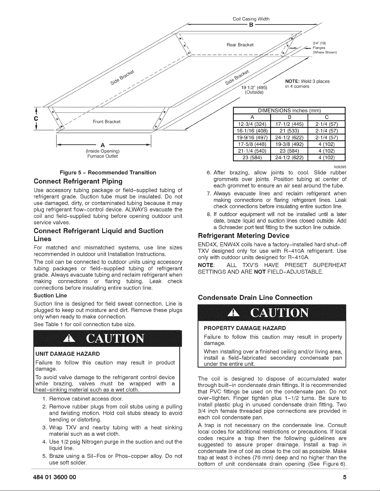
Cail
Casing
Width
B
Fe,
>
Rear
Bracket
3/4"
(19)
\
Flanges
Oo
(Where
Shown)
CL
“a
a“
C
“a
x
<
x
ex?
@
Ls
2
esos
go?
co
eo?
NOTE:
Weld
3
places
eo
19
1/2”
(495)
in
4
corners
eo
(Outside)
a
a
“a
“
fh
a
i
DIMENSIONS
Inches
(mm)
¢c
*
oo
Ae
A
B
Cc
|
oo
Front
Bracket
12-3/4
(324)
|
17-1/2
(445)
|
2-1/4
(57)
16-1/16
(408)
[21
(533)
2-1/4
(57)
|
19-9/16
(497)
|
24-1/2
(622)
|
2-1/4
(57)
|
A
|
17-5/8
(448)
|
19-3/8
(492)
4
(102)
(Inside
Opening)
21-1/4
(540) 23 (584)
4
(102)
Furnace
Outlet
23
(584)
24-1/2
(622)
4
(102)
Figure
5
-
Recommended
Transition
Connect
Refrigerant
Piping
Use
accessory
tubing
package
or
field-supplied
tubing
of
refrigerant
grade.
Suction
tube
must
be
insulated.
Do
not
use
damaged,
dirty,
or
contaminated
tubing
because
it
may
plug
refrigerant
flow—control
device.
ALWAYS
evacuate
the
coil
and
field~supplied
tubing
before
opening
outdoor
unit
service
valves.
Connect
Refrigerant
Liquid
and
Suction
Lines
For
matched
and
mismatched
systems,
use
line
sizes
recommended
in
outdoor
unit
Installation
Instructions.
The
coil
can
be
connected
to
outdoor
units
using
accessory
tubing
packages
or
field—supplied
tubing
of
refrigerant
grade.
Always
evacuate
tubing
and
reclaim
refrigerant
when
making
connections
or
flaring
tubing.
Leak
check
connections
before
insulating
entire
suction
line.
Suction
Line
Suction
line
is
designed
for
field
sweat
connection.
Line
is
plugged
to
keep
out
moisture
and
dirt.
Remove
these
plugs
only
when
ready
to
make
connection.
See
Table
i
for
coil
connection
tube
size.
4&
CAUTION
UNIT
DAMAGE
HAZARD
Failure
to
follow
this
caution
may
result
in
product
damage.
To
avoid valve
damage
to
the
refrigerant
control
device
while
brazing,
valves
must
be
wrapped
with
a
heat-sinking
material
such
as
a
wet
cloth.
1.
Remove
cabinet
access
door.
2.
Remove
rubber
plugs
from
coil
stubs
using
a
pulling
and
twisting
motion.
Hold
coil
stubs
steady
to
avoid
bending
or
distorting.
3.
Wrap
TXV
and
nearby
tubing
with
a
heat
sinking
material
such
as
a
wet
cloth.
4.
Use
1/2
psig
Nitrogen
purge
in
the
suction
and
out
the
liquid
line.
5.
Braze
using
a
Sil-Fos
or
Phos—copper
alloy.
Do
not
use
soft
solder.
A09395
6.
After
brazing,
allow
joints
to
cool.
Slide
rubber
grommets
over
joints.
Position
tubing
at
center
of
each
grommet
to
ensure
an
air
seal
around
the
tube.
7.
Always
evacuate
lines
and
reclaim
refrigerant
when
making
connections
or
flaring
refrigerant
lines.
Leak
check
connections
before
insulating
entire
suction
line.
8.
If
outdoor
equipment
will
not
be
installed
until
a
later
date,
braze
liquid
and
suction
lines
closed
outside.
Add
a
Schraeder
port
test
fitting
to
the
suction
line
outside.
Refrigerant
Metering
Device
END4X, ENW4xX
coils
have
a
factory-installed
hard
shut-off
TXV
designed
only
for
use
with
R-410A
refrigerant.
Use
only
with
outdoor
units
designed
for
R-410A.
NOTE:
ALL
TXV’'S
HAVE
PRESET
SUPERHEAT
SETTINGS
AND
ARE NOT
FIELD-ADJUSTABLE.
Condensate
Drain
Line
Connection
4.
CAUTION
PROPERTY
DAMAGE
HAZARD
Failure
to
follow
this
caution
may
result
in
property
damage.
When
installing
over
a
finished
ceiling
and/or
living
area,
install
a
field—fabricated
secondary
condensate
pan
under
the
entire
unit.
The
coil
is
designed
to
dispose
of
accumulated
water
through
built-in
condensate
drain
fittings.
It
is
recormmended
that
PVC
fittings
be
used
on
the
condensate
pan.
Do
not
over-tighten.
Finger
tighten
plus
1-1/2
turns.
Be
sure
to
install
plastic
plug
in
unused
condensate
drain
fitting.
Two
3/4
inch
female
threaded
pipe
connections
are
provided
in
each
coil
condensate
pan.
A
trap
is
not
necessary
on
the
condensate
line.
Consult
local
codes
for
additional
restrictions
or
precautions.
If
local
codes
require
a
trap
then
the
following
guidelines
are
suggested
to
assure
proper
drainage.
Install
a
trap
in
condensate
line
of
coil
as
close
to
the
coil
as
possible.
Make
trap
at
least
3
inches
(76
mm)
deep
and
no
higher
than
the
bottom
of
unit
condensate
drain
opening
(See
Figure
6).
484
071
3600
00
5
Loading ...
Loading ...