NOTE:
Read
the
entire
instruction
manual
before
starting
the
installation.
TABLE
OF
CONTENTS
PAGE
SAFETY
CONSIDERATIONS
....................0005.
1
INTRODUCTION
...
00...
nee
2
INSTALLATION
2.0.0.0.
00s
2
Airflow
oo.
teens
2
TXV
eens
2
Inspect
Equipment
..............00
0.00
cee
eee
2
Select
Installation
Procedure
.......................
2
Installation
of
Furnace
Coils
.....................05.
3
Connect
Refrigerant
Piping
......................00.
5
Connect
Refrigerant
Liquid
and
Suction
Lines
.........
5
Refrigerant
Metering
Device
.....................05.
5
Condensate
Drain
Line
Connection
..................
5
Waste
Line
Connection
.............0..
00000.
c
eee
6
Humidifier
Application
.......00.0.0.00.0
0.000022
eee
6
Model
Number
Identification
........................
7
SAFETY
CONSIDERATIONS
Improper
installation,
adjustment,
alteration,
service,
maintenance,
or
use
can
cause
explosion,
fire,
electrical
shock,
or
other
conditions
which
may
cause
death,
personal
injury
or
property
damage.
Consult
a
qualified
installer,
service
agency,
or
your
distributor
or
branch
for
information
or
assistance.
The
qualified
installer
or
agency
must
use
factory—authorized
kits
or
accessories
when
modifying
this
product.
Refer
to
the
individual
instructions
packaged
with
the
kits
or
accessories
when
installing.
Follow
all
safety
codes.
Wear
safety
glasses,
protective
clothing,
and
work
gloves.
Use
quenching
cloth
for
brazing
operations.
Have
fire
extinguisher
available.
Read
these
instructions
thoroughly
and
follow
all
warning
or
cautions
included
in
literature
and
attached
to
the
unit.
Consult
local
building
codes
and
the
current
editions
of
the
National
Electrical
Code
(NEC)
NFPA
70.
In
Canada,
refer
to
the
current
editions
of
the
Canadian
Electrical
Code
CSA
C22.1.
Recognize
safety
information.
When
you see
this
symbol
AX
on
the
unit
and
in
instructions
or
manuals,
be
alert
to
the
potential
for
personal
injury.
Understand
the
signal
words
DANGER,
WARNING,
CAUTION,
and
NOTE.
These
words
are
used
with
the
safety-alert
symbol.
DANGER
identifies
the
most
serious
hazards
which
will
result
in
severe
personal
injury
or
death.
WARNING
signifies
hazards
which
could
result
in
personal
injury
or
death.
CAUTION
is
used
to
identify
unsafe
practices
which
may
result
in
minor
personal
injury
or
product
and
property
damage.
NOTE
is
used
to
highlight
suggestions
which
will
result
in
enhanced
installation,
reliability,
or
operation.
IMPORTANT.
Nitrogen
can
leak
out
through
the
hole
that
the
needle
pierced
in
the
plugs.
This
does
not
indicate
a
leaking
coil
nor
warrant
return
of
the
coil.
ELECTRICAL
SHOCK
HAZARD
Failure
to
follow
this
warning
could
result
in
personal
injury
or
death.
Before
installing,
modifying
or
servicing
system,
always
turn
off
main
power
to
system.
There
may
be
more
than
one
disconnect
switch.
Lock
out
and
tag
switch
with
a
suitable
warning
label.
4
CAUTION
PERSONAL
INJURY
HAZARD
Failure
to
follow
this
caution
may
result
in
personal
injury.
This
coil
contains Nitrogen
precharge
of
15
PSIG.
Release
of
this
pressure
through
the
center
of
the
rubber
plugs
is
required
before
removing
the
pluas.
4
CAUTION
ENVIRONMENTAL
HAZARD
Failure
to
follow
this
caution
may
result
in
environmental
pollution.
Remove
and
recycle
all
components
or
materials
(i.e.
oil,
refrigerant,
etc.)
before
unit
final
disposal.
4.
CAUTION
CUT
HAZARD
Failure
to
follow
this
caution
may
result
in
personal
injury.
Sheet
metal
parts
may
have
sharp
edges
or
burrs.
Use
care
and
wear
appropriate
protective
clothing
and
gloves
when
handling
parts.
484
01
3600
00
April
2010
INTRODUCTION
Use
this
instruction
manual
to
install
indoor
coils
on
upflow
or
downflow
furnaces.
Do
not
install
coil
in
horizontal
position.
Coils
are
enclosed
in
a
painted
casing
have
factory-installed
TXV’s.
These
coils
are
used
with
R-410A
refrigerant
systems.
INSTALLATION
NOTE:
Models
with
tin-plated
copper
coils,
“T”
in
the
8th
position
of
the
model
number,
are
installed
the
same
as
standard
copper
coils.
These
units
can
be
installed
in
multiple
configurations.
Before
installation,
there
are
several
performance
requirements
that
must
be
considered
because
poor
installation
can
negatively
alter
performance.
This
section
will
briefly
discuss
those
factors.
Airflow
Airflow
amount
and
distribution
are
vital
to
adequate
system
performance.
Problems
that
can
be
experienced
with
incorrect
airflow
include:
e
low
system
performance
*
restricted
TXV
°
frosted
coil
*
poor
humidity
control
¢
water
blow-off
When
attaching
the
coil
and
building
the
plenum,
pay
special
attention
to
the
effect
these
details
will
have
on
airflow.
After
system
start-up,
check
the
cfm
to
insure
that
it
is
correct.
(Generally,
the
cfm
should
be
350
to
400
cfm/ton
during
normal
cooling
operation.)
TXV
A
thermal
expansion
valve
is
utilized
in
this
coil
design
to
optimize
performance
and
comfort
throughout
the
entire
operating
range
of
the
system.
Special
attention
needs
to
be
taken
to
the
TXV
when
installing
the
coil
¢
Do
not
overheat
valve.
Temperatures
that
exceed
212°F
(100°C)
can
harm
valve
performance.
Use
a
wet
cloth
or
heat
sink
when
brazing.
e
Place
liquid
filter
dryer
near
ID
unit
to
reduce
the
risk
of
debris
clogging
the
valve.
e
Make
sure
TXV
bulb
is
securely
fastened
and
wrapped
in
the
indentation
on
vapor
line
tube.
END4X,
ENW4X
coils
have
a
factory—installed
hard—shutoff
TXV
designed
only
for
use
with
R-410A
refrigerant.
Use
only
with
outdoor
units
designed
for
R-410A.
NOTE:
All
TXV’S
have
preset
superheat
settings
and
are
not
field—adjustable.
Cabinet
Sweating
If
this
unit
is
installed
in
a
garage,
attic,
or
other
unconditioned
space,
special
attention
needs
to
be
given
to
the
potential
of
cabinet
sweating.
A
6-in
(152
mm)
wide
piece
of
insulation
should
be
wrapped
around
the
coil
casing
and
supply
duct
connection
point.
inspect
Equipment
File
claim
with
shipper
if
equipment
is
damaged.
Select
Installation
Procedure
4&
CAUTION
PROPERTY
DAMAGE
HAZARD
Failure
to
follow
this
caution
may
result
in
property
damage.
Installing
coils
rotated
90°
from
the front
of
the
furnace,
in
upflow
or
downflow
applications,
may
cause
water
blow-off
or
coil
freeze—up
due
to
the
concentration
of
air
on
one
slab
of
the
coil
or
lack
of
air
to
a
slab
in
the
coil.
It
is
recommended
that
on
this
type
of
application,
a
field~supplied
adapter
be
placed
between
the
coil
and
furnace
to
allow
air
to
distribute
properly
between
all
slabs
of
the
coil.
NOTE:
Furnace
coils
are
not
approved
to
be
used
in
fan
coil
or
“draw-through”
type
applications.
To
install
cased
coils
in
upflow
applications,
follow
the
instructions
below,
Upflow
Cased
Coil
Installation.
To
install
cased
coils
in
downflow
applications,
follow
the
instructions
below,
Downflow
Cased
Coil
Installation.
See
Table
1
for
dimensions
and
overhang
options.
Refer
to
instructions
for
placement
of
coil
casing
on
furnace.
484
071
3600
00
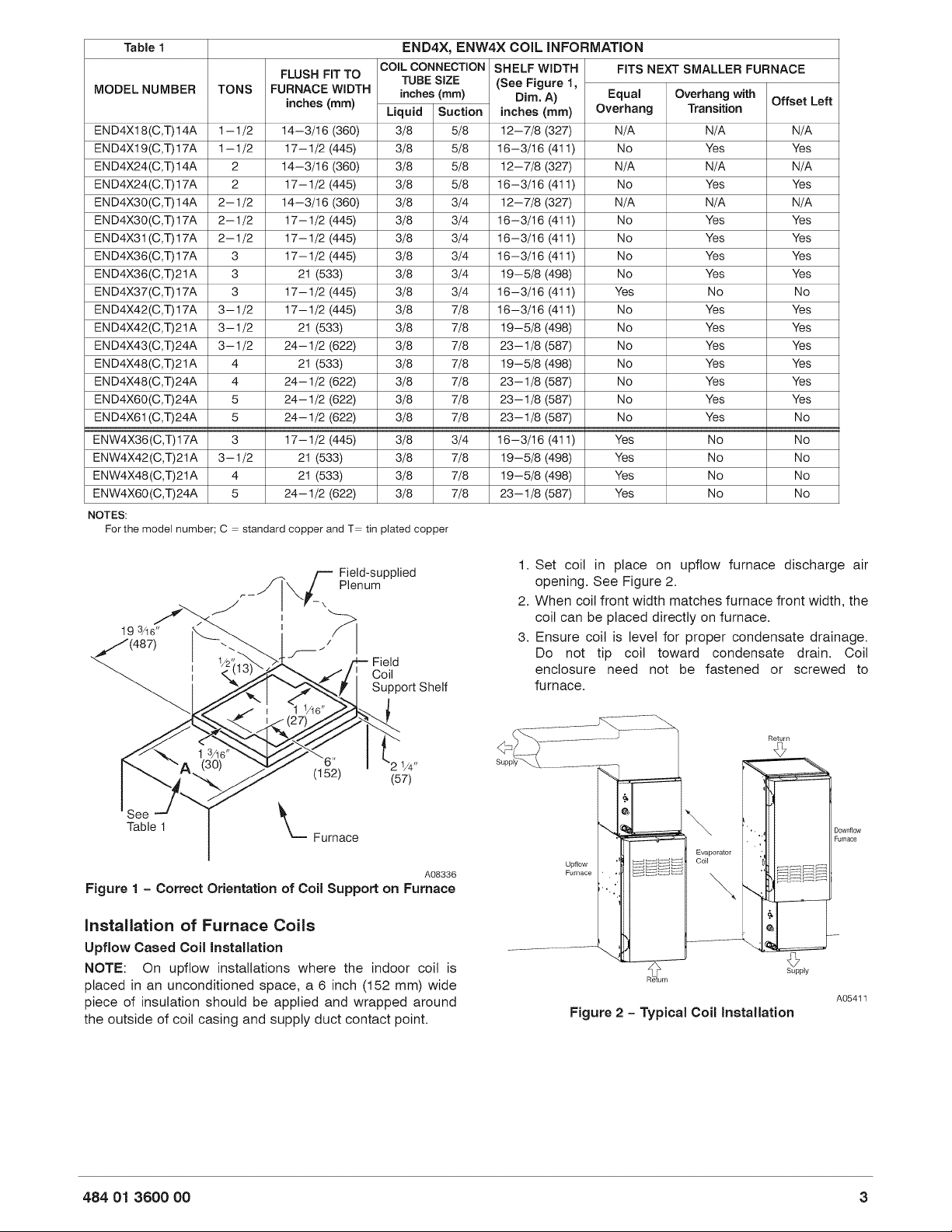
Table
1
END4X,
ENW4X
COIL
INFORMATION
FLUSH FITTO
[COL
CONNECTION
SHELF
WIDTH
FITS
NEXT
SMALLER
FURNACE
MODEL
NUMBER
|
TONS
inches
(mm)
inches
(mm)
Dim.
A)
,
Equal
Overhang
with
Offset
Left
Liquid
[Suction
|
inches
(mm)
|
Overhang
Transition
END4x18(C,1)14A
|
1-1/2
|
14—3/16
(360)
3/8
5/8
|
12—7/8
(327)
N/A N/A
N/A
END4xX19(C,1)17A
|
1-1/2
|
17—1/2
(445)
3/8
5/8
|
163/16
(411)
No
Yes
Yes
END4X24(C,1)14A
|
2
14—3/16
(360)
3/8
5/8
|
12—7/8
(327)
N/A N/A
N/A
END4x24(G,1)17A
|
2
17—1/2
(445)
3/8
5/8
|
163/16
(411)
No
Yes
Yes
END4x30(C,1)14A
|
2-1/2
|
14—3/16
(360)
3/8
3/4
|
12—7/8
(27)
N/A N/A
N/A
END4X30(C,1)17A
|
2-1/2
|
17—1/2
(445)
3/8
3/4
|
163/16
(411)
No
Yes
Yes
END4X31(C,1)17A
|
2-1/2
|
17—1/2
(445)
3/8
3/4
|
163/16
(411)
No
Yes
Yes
END4X36(C,1)17A
|
3
17—1/2
(445)
3/8
3/4
|
163/16
(411)
No
Yes
Yes
END4x36(C,T)21A
|
3
21
(533)
3/8
3/4
|
19—5/8
(498)
No
Yes
Yes
END4X37(C,1)17A
|
3
17—1/2
(445)
3/8
3/4
|
163/16
(411)
Yes
No No
END4xX42(C,1)17A
|
3-1/2
|
17—1/2
(445)
3/8
7/8
|
163/16
(411)
No
Yes
Yes
END4x42(6,1)21A
|
3-1/2
21
(633)
3/8
7/8
|
19—5/8
(498)
No
Yes
Yes
END4xX43(C,1)244
|
3-1/2
|
24—1/2
(622)
3/8
7/8
|
23—1/8
(687)
No
Yes
Yes
END4X48(C,1)21A
|
4
21
(633)
3/8
7/8
|
19—5/8
(498)
No
Yes
Yes
END4X48(C,1)244
|
4
24—1/2
(622)
3/8
7/8
|
23—1/8
(687)
No
Yes
Yes
END4X60(C,1)244
|
5
24—1/2
(622)
3/8
7/8
|
23—1/8
(687)
No
Yes
Yes
END4X61(C,1)244
|
5
24—1/2
(622)
3/8
7/8
|
23—1/8
(687)
No
Yes
No
ENW4X36(C,1)17A
|
3
17—1/2
(445)
3/8
3/4
|
16—3/16
(411)
Yes
No
No
ENW4x42(C,T)21A
|
3-1/2
21
(633)
3/8
7/8
|
19—5/8
(498)
Yes
No No
ENW4xX48(C,T)21A
|
4
21
(633)
3/8
7/8
|
19—5/8
(498)
Yes
No No
ENW4xX60(C,T)24A
|
5
24—1/2
(622)
3/8
7/8
|
23—1/8
(687)
Yes
No No
NOTES:
For the
model
number;
C
=
standard
copper
and
T=
tin
plated
copper
See
Table
1
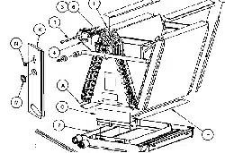
a
Furnace
Field-supplied
Plenum
A08336
Figure
1
-
Correct
Orientation
of
Coil
Support
on
Furnace
Installation
of
Furnace
Coils
Upfiow
Cased
Coil
Installation
NOTE:
On upflow
installations
where
the
indoor
coil
is
placed
in
an
unconditioned
space,
a
6
inch
(152
mm)
wide
piece
of
insulation
should
be
applied
and
wrapped
around
the
outside
of
coil
casing
and
supply
duct
contact
point.
1.
Set
coil
in
place
on
upflow
furnace
discharge
air
opening.
See
Figure
2.
2.
When
coil
front
width
matches
furnace
front
width,
the
coil
can
be
placed
directly
on
furnace.
3.
Ensure
coil
is
level
for
proper
condensate
drainage.
Do
not
tip
coil
toward
condensate
drain.
Coil
enclosure
need
not
be
fastened
or
screwed
to
furnace.
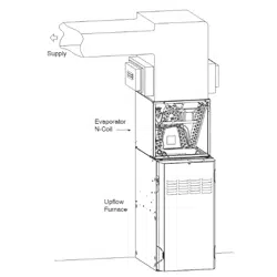
a
Supply
Downflow
Furnace
Upflow
Furnace
Return
A05411
Figure
2
-
Typical
Coil
Installation
484
071
3600
00

NOTE:
When
ENW4X
coils
are
applied
to
same
width
furnace,
remove
block-off
plates
at
casing
base
by
removing
2
screws
per
plate
from
side
of
casing.
See
Figure
3.
Block-Off
A05412
Figure
3
-
Block-Off
Plate
Removal
ENW4X
MODEL
COILS
APPLIED
CENTERED
OVER
NARROW
FURNACE
1.
There
is
no
transition
required
for
this
application.
2.
Remove
coil
from
packaging
and
place
on
top
of
furnace
with
1
5/8
inch
(41
mm)
overhang
on
both
sides.
See
Figure
4,
Alternative
A.
3.
Continue
with
normal
installation
practices.
See
Connect
Refrigerant
Piping.
STANDARD
MODEL
COILS
APPLIED
CENTERED
OVER
NARROW
FURNACE
REQUIRE
A
MINIMUM
TRANSITION
AS
SPECIFIED
IN
Figure
5.
1.
Prepare
transition,
following
recommended
transition
drawing.
See
Figure
5.
2.
Place
transition
on
top
of
gas
furnace.
See
Figure
4,
Alternative
B.
Secure
with
sheet
metal
screws.
Place
coil
on
top
of
transition.
Make
sure
coil
rests
evenly
on
top
of
transition
and
gas
furnace.
3.
Secure
coil
to
transition
using
sheet
metal
screws.
4.
Continue
with
normal
installation
practices.
See
Connect
Refrigerant
Piping.
NOTE:
[f
coil
is
not
being
installed
in
the
standard
orientation
(front
of
coil
matching
front
of
furnace)
then
coil
must
be
raised
above
furnace
as
specified
in
Figure
5.
STANDARD
MODEL
COILS
APPLIED
DIRECTLY
ON
TOP
AND
OFFSET
TO
THE
LEFT
ON
NARROW
FURNACE
1.
Notch
support
rail
on
underside
of
coil
cabinet
to
provide
clearances
for
gas
furnace
flange.
This
rail
is
not
visible
from
front
of
coil.
To
locate
position
of
notch,
place
coil
directly
on
top
of
gas
furnace
with
overhanging
portion
entirely
on
left
side
as
in
Figure
4,
Alternative
C.
Mark
location
of
gas
furnace
flange
on
coil
casing.
Remove
coil
from
top
of
furnace.
Using
tin
snips,
make
a
notch
in
rail
large
enough
to
allow
clearance
for
gas
flow
furnace
flange.
2.
Place
coil
on
top
of
gas
furnace.
Make
sure
coil
is
shifted
completely
to
left
side,
and
notch
is
sufficient
so
coil
rests
on
top
of
furnace
cabinet.
3.
Prepare
and
install
block-off
plate.
See
Figure
4,
Alternative
C.
Using
field-supplied
sheet
metal,
cut
a
block-off
plate
to
be
attached
to
bottom
left
side
of
coil
casing.
This
plate
prevents
air
leakage
from
overhanging
portion
of
coil.
Attach
plate
using
sheet
metal
screws.
4.
Continue
with
normal
installation
practices.
See
Connect
Refrigerant
Piping.
0 8
®
me
2
1/4”
(57)
@
t
ALTERNATIVE
B
ENW4X
Models
Only
o o
0
0
[%
%
Field
Fabricated
Block-off
Plate
ALTERNATIVE
c
A08337
Figure
4
-
Alternative
Coil
Mounting
Positions
Downflow
Cased
Coil
Installation
1.
Place
N-coil
on
supply
duct
opening.
2.
When
coil
width
matches
furnace
width,
furnace
can
be
placed
directly
on
the
cased
coil.
NOTE:
In
downflow
installation
with
a
4—way
multipoise
furnace,
break
off
perforated
duct
flanges
on
furnace.
See
Furnace
Installation
Instructions.
3.
Coils
that
under-hang
(narrower
than
furnace)
must
have
a
field-fabricated
transition
between
furnace
and
N-coil
casing
as
specified
in
Figure
5.
4.
Coils
that
overhang
(wider than
furnace)
do
not
require
a
transition
in
downflow
application.
However,
a
field-supplied
furnace
shelf
should
be
constructed
to
fit
furnace
to
coil
opening.
5.
Place
furnace
on
top
of
N-coil
casing,
or
field~supplied
furnace
shelf.
484
071
3600
00
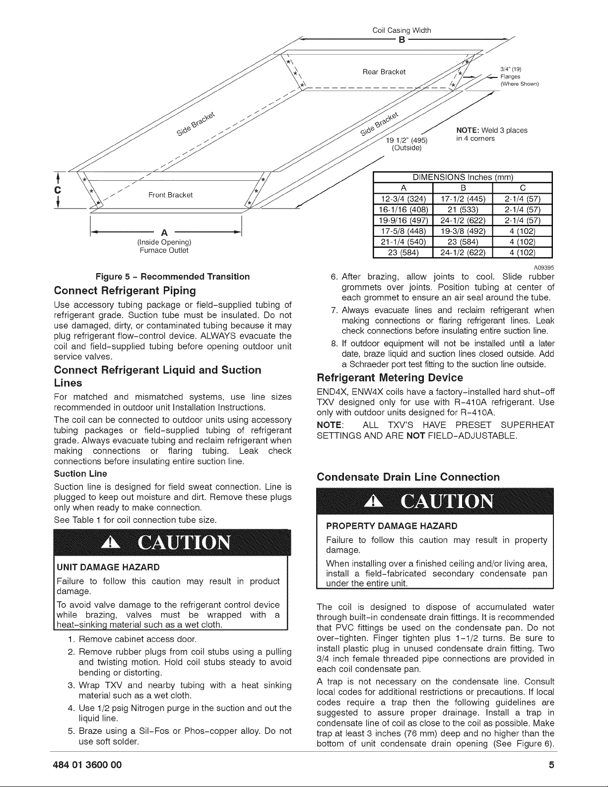
Cail
Casing
Width
B
Fe,
>
Rear
Bracket
3/4"
(19)
\
Flanges
Oo
(Where
Shown)
CL
“a
a“
C
“a
x
<
x
ex?
@
Ls
2
esos
go?
co
eo?
NOTE:
Weld
3
places
eo
19
1/2”
(495)
in
4
corners
eo
(Outside)
a
a
“a
“
fh
a
i
DIMENSIONS
Inches
(mm)
¢c
*
oo
Ae
A
B
Cc
|
oo
Front
Bracket
12-3/4
(324)
|
17-1/2
(445)
|
2-1/4
(57)
16-1/16
(408)
[21
(533)
2-1/4
(57)
|
19-9/16
(497)
|
24-1/2
(622)
|
2-1/4
(57)
|
A
|
17-5/8
(448)
|
19-3/8
(492)
4
(102)
(Inside
Opening)
21-1/4
(540) 23 (584)
4
(102)
Furnace
Outlet
23
(584)
24-1/2
(622)
4
(102)
Figure
5
-
Recommended
Transition
Connect
Refrigerant
Piping
Use
accessory
tubing
package
or
field-supplied
tubing
of
refrigerant
grade.
Suction
tube
must
be
insulated.
Do
not
use
damaged,
dirty,
or
contaminated
tubing
because
it
may
plug
refrigerant
flow—control
device.
ALWAYS
evacuate
the
coil
and
field~supplied
tubing
before
opening
outdoor
unit
service
valves.
Connect
Refrigerant
Liquid
and
Suction
Lines
For
matched
and
mismatched
systems,
use
line
sizes
recommended
in
outdoor
unit
Installation
Instructions.
The
coil
can
be
connected
to
outdoor
units
using
accessory
tubing
packages
or
field—supplied
tubing
of
refrigerant
grade.
Always
evacuate
tubing
and
reclaim
refrigerant
when
making
connections
or
flaring
tubing.
Leak
check
connections
before
insulating
entire
suction
line.
Suction
Line
Suction
line
is
designed
for
field
sweat
connection.
Line
is
plugged
to
keep
out
moisture
and
dirt.
Remove
these
plugs
only
when
ready
to
make
connection.
See
Table
i
for
coil
connection
tube
size.
4&
CAUTION
UNIT
DAMAGE
HAZARD
Failure
to
follow
this
caution
may
result
in
product
damage.
To
avoid valve
damage
to
the
refrigerant
control
device
while
brazing,
valves
must
be
wrapped
with
a
heat-sinking
material
such
as
a
wet
cloth.
1.
Remove
cabinet
access
door.
2.
Remove
rubber
plugs
from
coil
stubs
using
a
pulling
and
twisting
motion.
Hold
coil
stubs
steady
to
avoid
bending
or
distorting.
3.
Wrap
TXV
and
nearby
tubing
with
a
heat
sinking
material
such
as
a
wet
cloth.
4.
Use
1/2
psig
Nitrogen
purge
in
the
suction
and
out
the
liquid
line.
5.
Braze
using
a
Sil-Fos
or
Phos—copper
alloy.
Do
not
use
soft
solder.
A09395
6.
After
brazing,
allow
joints
to
cool.
Slide
rubber
grommets
over
joints.
Position
tubing
at
center
of
each
grommet
to
ensure
an
air
seal
around
the
tube.
7.
Always
evacuate
lines
and
reclaim
refrigerant
when
making
connections
or
flaring
refrigerant
lines.
Leak
check
connections
before
insulating
entire
suction
line.
8.
If
outdoor
equipment
will
not
be
installed
until
a
later
date,
braze
liquid
and
suction
lines
closed
outside.
Add
a
Schraeder
port
test
fitting
to
the
suction
line
outside.
Refrigerant
Metering
Device
END4X, ENW4xX
coils
have
a
factory-installed
hard
shut-off
TXV
designed
only
for
use
with
R-410A
refrigerant.
Use
only
with
outdoor
units
designed
for
R-410A.
NOTE:
ALL
TXV’'S
HAVE
PRESET
SUPERHEAT
SETTINGS
AND
ARE NOT
FIELD-ADJUSTABLE.
Condensate
Drain
Line
Connection
4.
CAUTION
PROPERTY
DAMAGE
HAZARD
Failure
to
follow
this
caution
may
result
in
property
damage.
When
installing
over
a
finished
ceiling
and/or
living
area,
install
a
field—fabricated
secondary
condensate
pan
under
the
entire
unit.
The
coil
is
designed
to
dispose
of
accumulated
water
through
built-in
condensate
drain
fittings.
It
is
recormmended
that
PVC
fittings
be
used
on
the
condensate
pan.
Do
not
over-tighten.
Finger
tighten
plus
1-1/2
turns.
Be
sure
to
install
plastic
plug
in
unused
condensate
drain
fitting.
Two
3/4
inch
female
threaded
pipe
connections
are
provided
in
each
coil
condensate
pan.
A
trap
is
not
necessary
on
the
condensate
line.
Consult
local
codes
for
additional
restrictions
or
precautions.
If
local
codes
require
a
trap
then
the
following
guidelines
are
suggested
to
assure
proper
drainage.
Install
a
trap
in
condensate
line
of
coil
as
close
to
the
coil
as
possible.
Make
trap
at
least
3
inches
(76
mm)
deep
and
no
higher
than
the
bottom
of
unit
condensate
drain
opening
(See
Figure
6).
484
071
3600
00
5
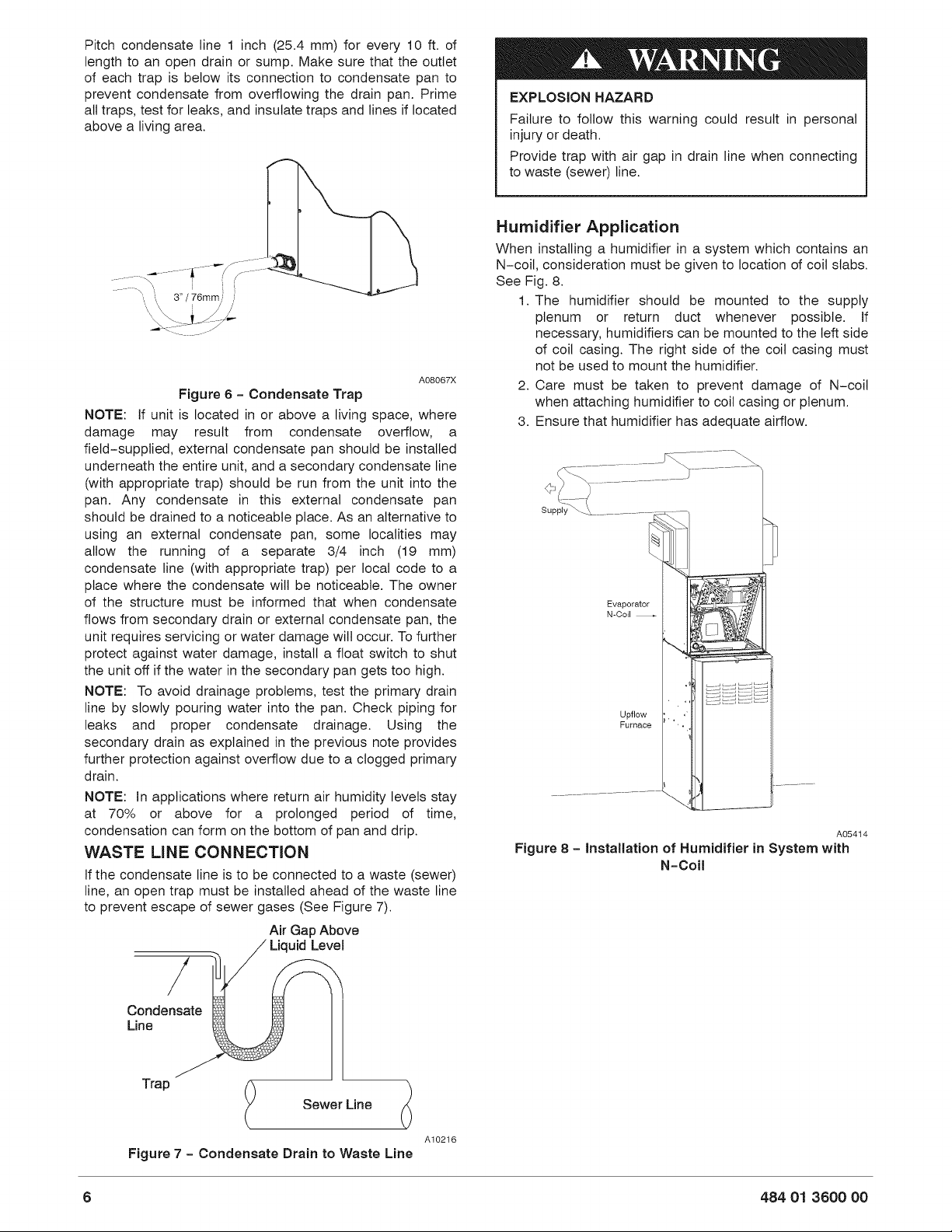
Pitch
condensate
line
1
inch
(25.4
mm)
for
every
10
ft.
of
length
to
an
open
drain
or
sump.
Make
sure
that
the
outlet
of
each
trap
is
below
its
connection
to
condensate
pan
to
prevent
condensate
from
overflowing
the
drain
pan.
Prime
all
traps,
test
for
leaks,
and
insulate
traps
and
lines
if
located
above
a
living
area.
AQ8067X
Figure
6
-
Condensate
Trap
NOTE:
If
unit
is
located
in
or
above
a
living
space,
where
damage
may
result
from
condensate
overflow,
a
field~supplied,
external
condensate
pan
should
be
installed
underneath
the
entire
unit,
and
a
secondary
condensate
line
(with
appropriate
trap)
should
be
run
from
the
unit
into
the
pan.
Any
condensate
in
this
external
condensate
pan
should
be
drained
to
a
noticeable
place.
As
an
alternative
to
using
an
external
condensate
pan,
some
localities
may
allow
the
running
of
a
separate
3/4
inch
(19
mm)
condensate
line
(with
appropriate
trap)
per
local
code
to
a
place
where
the
condensate
will
be
noticeable.
The
owner
of
the
structure
must
be
informed
that
when
condensate
flows
from
secondary
drain
or
external
condensate
pan,
the
unit
requires
servicing
or
water
damage
will
occur.
To
further
protect
against
water
damage,
install
a
float
switch
to
shut
the
unit
off
if
the
water
in
the
secondary
pan
gets
too
high.
NOTE:
To
avoid
drainage
problems,
test
the
primary
drain
line
by
slowly
pouring
water
into
the
pan.
Check
piping
for
leaks
and
proper
condensate
drainage.
Using
the
secondary
drain
as
explained
in
the
previous
note
provides
further
protection
against
overflow
due
to
a
clogged
primary
drain.
NOTE:
In
applications
where
return
air
humidity
levels
stay
at
70%
or
above
for
a
prolonged
period
of
time,
condensation
can
form
on
the
bottom
of
pan
and
drip.
WASTE
LINE
CONNECTION
If
the
condensate
line
is
to
be
connected
to
a
waste
(sewer)
line,
an
open
trap
must
be
installed
ahead
of
the
waste
line
to
prevent
escape
of
sewer
gases
(See
Figure
7).
Air
Gap
Above
Liquid
Level
Condensate
§&
Line
|
Sewer
Line
A10216
Figure
7
-
Condensate
Drain
to
Waste
Line
EXPLOSION
HAZARD
Failure
to
follow
this
warning
could
result
in
personal
injury
or
death.
Provide
trap with
air
gap
in
drain
line
when
connecting
to
waste
(sewer)
line.
Humidifier
Application
When
installing
a
humidifier
in
a
system
which
contains
an
N-coil,
consideration
must
be
given
to
location
of
coil
slabs.
See
Fig.
8.
1.
The
humidifier
should
be
mounted
to
the
supply
plenum
or
return
duct
whenever
possible.
If
necessary,
humidifiers
can
be
mounted
to
the
left
side
of
coil
casing.
The
right
side
of
the
coil
casing
must
not
be
used
to
mount
the
humidifier.
2.
Care
must
be
taken
to
prevent
damage
of
N-coil
when
attaching
humidifier
to
coil
casing
or
plenum.
3.
Ensure
that
humidifier
has
adequate
airflow.
Evaporator
N-Goil
—+
Upflow
Furnace
Ce
A05414
Figure
8
-
Installation
of
Humidifier
in
System
with
N-Coil
484
071
3600
00
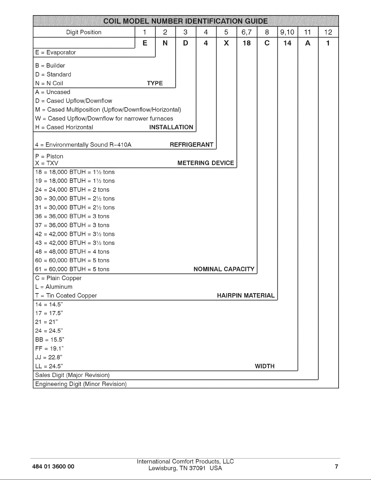
igit
Position
6,7
9,10
12
E
=
Evaporator
B
=
Builder
D
=
Standard
N=WN
Coil
TYPE
A
=
Uncased
D
=
Cased
Upflow/Downflow
H
=
Cased
Horizontal
M
=
Cased
Multiposition
(Upflow/Downflow/Horizonial)
W
=
Cased
Upflow/Downflow
for
narrower
furnaces
INSTALLATION
4
=
Environmentally
Sound
R-410A
REFRIGERANT
P
=
Piston
xX
=
TXV
METERING
DEVICE
18
=
18,000
BTUH
=
11%
tons
19
=
18,000
BTUH
=
11%
tons
24
=
24,000
BTUH
= 2
tons
30
=
30,000
BTUH
=
2%
tons
31
=
30,000
BTUH
=
2%
tons
36
=
36,000
BTUH
=
3
tons
37
=
36,000
BTUH
=
3
tons
42
=
42,000
BTUH
=
3%
tons
43
=
42,000
BTUH
=
3%
tons
48
=
48,000
BTUH
=
4
tons
60
=
60,000
BTUH
=
5
tons
61
=
60,000
BTUH
=
5
tons
NOMINAL
CAPACITY
18
C
=
Plain
Copper
L =
Aluminum
T
=
Tin
Coated
Copper
HAIRPIN
MATERIAL
14
=
14.5"
17
=
17.5"
21
=
21”
24
=
24,5"
BB
=
15.5”
FF
=
19.1"
JJ
=
22.8”
LL
=
24.5”
WIDTH
14
Sales
Digit
(Major
Revision)
Engineering
Digit
(Minor
Revision)
484
071
3600
00
International
Comfort
Products,
LLC
Lewisburg,
TN 37091
USA