
MPG Z790 CARBON WIFI
Motherboard
User Guide
Benutzerhandbuch
Manuel d’utilisation


1
Contents
Quick Start..................................................................................................................... 3
Specifications .............................................................................................................. 15
Special Features ......................................................................................................... 20
Package Contents ...................................................................................................... 21
Back Panel Connectors ............................................................................................. 22
LAN Port LED Status Table .................................................................................. 24
Audio Jacks Connection ....................................................................................... 24
Installing Antennas ............................................................................................... 26
Overview of Components ........................................................................................... 27
CPU Socket ........................................................................................................... 28
DIMM Slots ............................................................................................................ 29
PCI_E1~3: PCIe Expansion Slots .......................................................................... 30
M2_1~5: M.2 Slots (Key M) ................................................................................... 31
SATA5~8 & SATA_A1~A2: SATA 6Gb/s Connectors ............................................. 38
JTBT1: Thunderbolt Add-on Card Connector ...................................................... 38
JAUD1: Front Audio Connector ............................................................................ 39
JFP1, JFP2: Front Panel Connectors ................................................................... 39
CPU_PWR1~2, ATX_PWR1: Power Connectors ................................................... 40
JCI1: Chassis Intrusion Connector ....................................................................... 41
JDASH1 : Tuning Controller connector ................................................................ 41
JUSB4: USB 3.2 Gen 2x2 Type-C front panel Connector ..................................... 42
JUSB3: USB 3.2 Gen 1 Connector ........................................................................ 42
JUSB1~2: USB 2.0 Connectors ............................................................................. 43
JTPM1: TPM Module Connector ........................................................................... 43
CPU_FAN1, PUMP_FAN1, SYS_FAN1~5: Fan Connectors .................................. 44
JBAT1: Clear CMOS (Reset BIOS) Jumper ........................................................... 45
............................................................................................ 45
JRGB1: RGB LED connector ................................................................................. 46
JARGB_V2_1~2: A-RAINBOW V2 (ARGB Gen2) LED connectors ......................... 47
JOCFS1: Safe Boot Jumper .................................................................................. 48
English

2
Onboard LEDs ............................................................................................................. 49
EZ Debug LED ....................................................................................................... 49
JPWRLED1: LED power input ............................................................................... 49
LED_SW1: EZ LED Control ................................................................................... 49
Debug Code LED ................................................................................................... 50
Boot Phases .......................................................................................................... 50
Debug Code LED Table ......................................................................................... 50
Installing OS, Drivers & MSI Center .......................................................................... 57
MSI Center ............................................................................................................ 60
UEFI BIOS .................................................................................................................... 61
BIOS Setup ............................................................................................................ 62
Resetting BIOS ...................................................................................................... 63
Updating BIOS ....................................................................................................... 63

3
Quick Start
Thank you for purchasing a new motherboard from MSI®. This Quick Start section
provides demonstration diagrams about how to install your computer. Some of the
installations also provide video demonstrations. Please link to the URL to watch it
with the web browser on your phone or tablet. You may have even link to the URL by
scanning the QR code.
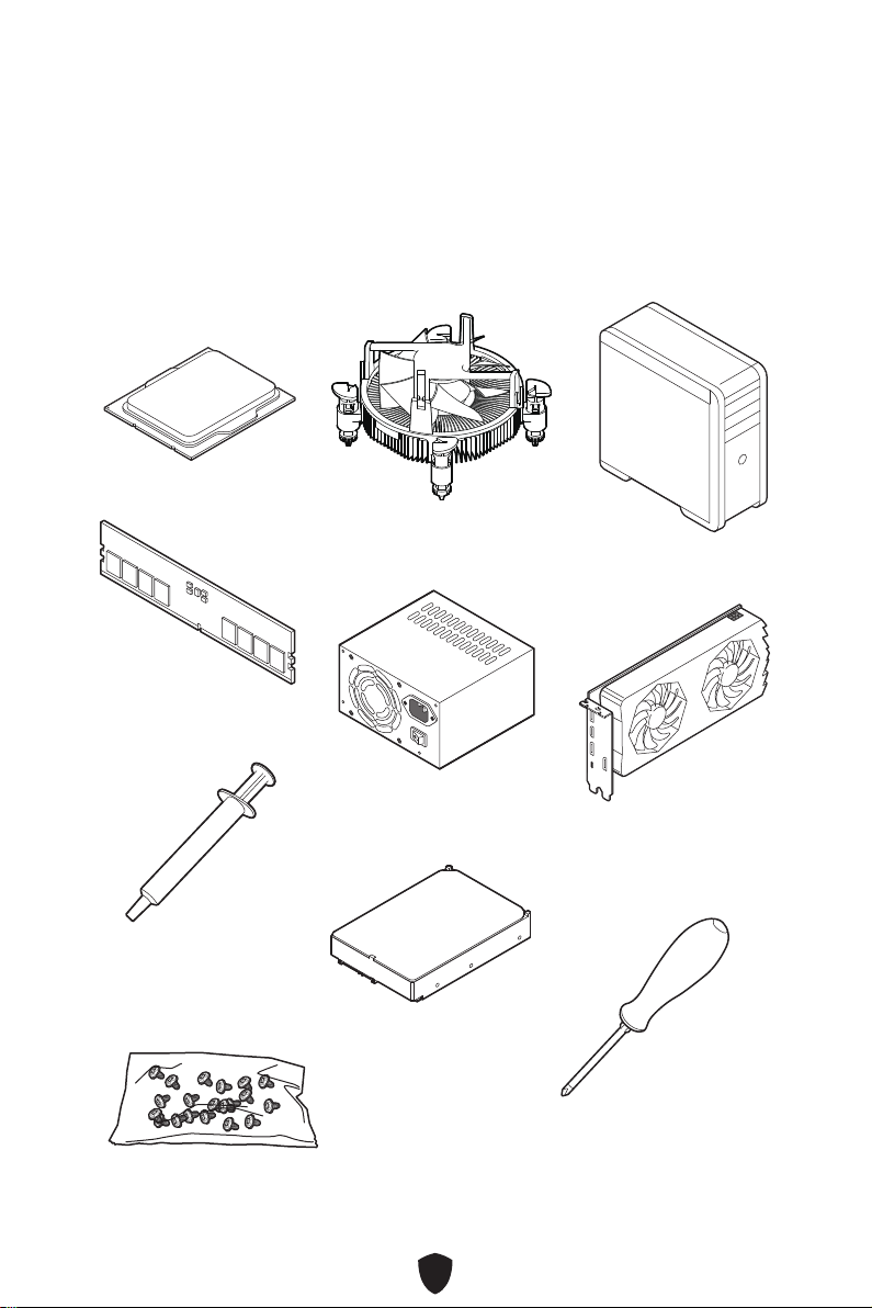
Preparing Tools and Components
Intel® LGA1700 CPU
LGA1700 CPU Fan
Graphics Card
SATA Hard Disk Drive
Phillips Screwdriver
Chassis
Power Supply Unit
A Package of Screws
Thermal Paste
DDR5 Memory

4
Safety Information
The components included in this package are prone to damage from electrostatic
discharge (ESD). Please adhere to the following instructions to ensure successful
computer assembly.
Ensure that all components are securely connected. Loose connections may cause
the computer to not recognize a component or fail to start.
Hold the motherboard by the edges to avoid touching sensitive components.
It is recommended to wear an electrostatic discharge (ESD) wrist strap when
handling the motherboard to prevent electrostatic damage. If an ESD wrist strap
is not available, discharge yourself of static electricity by touching another metal
object before handling the motherboard.
Store the motherboard in an electrostatic shielding container or on an anti-static
pad whenever the motherboard is not installed.
Before turning on the computer, ensure that there are no loose screws or metal
components on the motherboard or anywhere within the computer case.
Do not boot the computer before installation is completed. This could cause
permanent damage to the components as well as injury to the user.
If you need help during any installation step, please consult a certified computer
technician.
Always turn off the power supply and unplug the power cord from the power outlet
before installing or removing any computer component.
Keep this user guide for future reference.
Keep this motherboard away from humidity.
Make sure that your electrical outlet provides the same voltage as is indicated on
the PSU, before connecting the PSU to the electrical outlet.
Place the power cord such a way that people can not step on it. Do not place
anything over the power cord.
All cautions and warnings on the motherboard should be noted.
If any of the following situations arises, get the motherboard checked by service
personnel:
• Liquid has penetrated into the computer.
• The motherboard has been exposed to moisture.
• The motherboard does not work well or you can not get it work according to user
guide.
• The motherboard has been dropped and damaged.
• The motherboard has obvious sign of breakage.
Do not leave this motherboard in an environment above 60°C (140°F), it may damage
the motherboard.
5
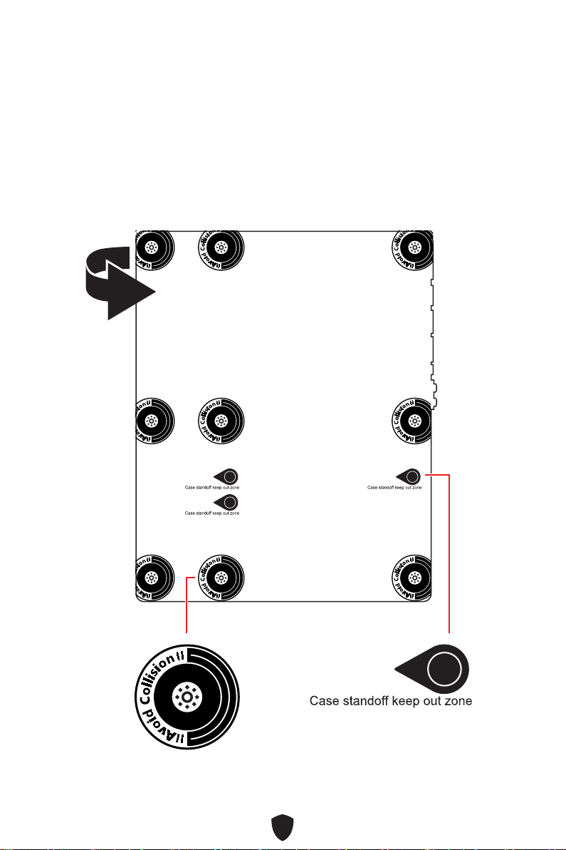
Case stand-off notification
To prevent damage to the motherboard, any unnecessary mounting stand-off between
the motherboard circuits and the computer case is prohibited. The Case standoff keep
out zone signs will be marked on the backside of motherboard (as shown below) to
serve as a warning to user.
Avoid collision notification
Protective paint is printed around each screw hole to prevent parts from being
scratched.

6
Installing a Processor
https://youtu.be/KMf9oIDsGes
11
22
33
66
44
55
77
88
99

7
Installing DDR5 memory
DIMMA2 DIMMA2
DIMMB2
DIMMA1
DIMMA2
DIMMB1
DIMMB2
https://youtu.be/XiNmkDNZcZk
8
HDD LED
RESET SW
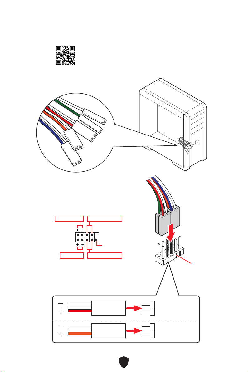
Connecting the Front Panel Header
http://youtu.be/DPELIdVNZUI
JFP1
HDD LED
HDD LED -
HDD LED +
POWER LED -
POWER LED +
POWER LED
RESET SW
POWER SW
POWER LED+
POWER LED-
HDD LED
1
2 10
9
Power LED
Reserved
Power Switch
JFP1
Reset SwitchHDD LED
9
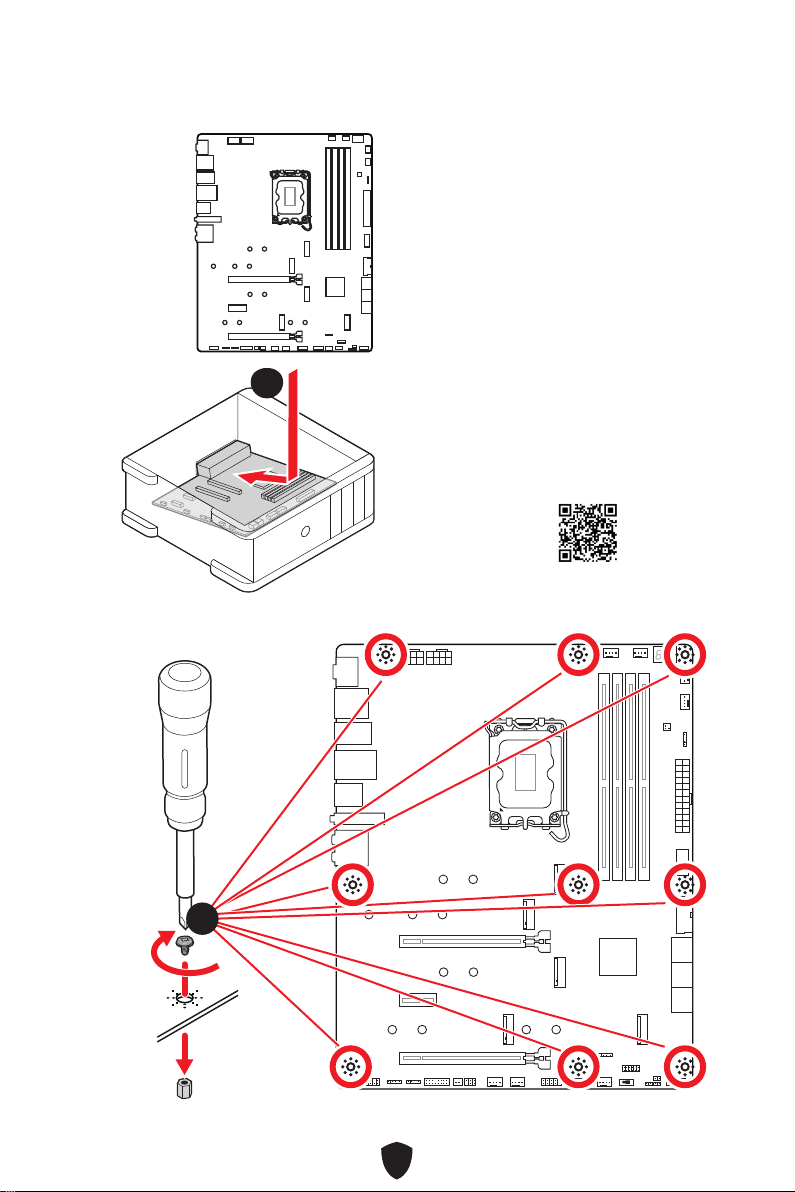
Installing the Motherboard
11
https://youtu.be/wWI6Qt51Wnc
Torque:
3 kgf·cm*
*3 kgf·cm
= 0.3 N·m
= 2.6 lbf·in
22

10
Connecting the Power Connectors
http://youtu.be/gkDYyR_83I4
CPU_PWR1
CPU_PWR2
ATX_PWR1

11
Installing SATA Drives
http://youtu.be/RZsMpqxythc
11
22
33
44
55
12
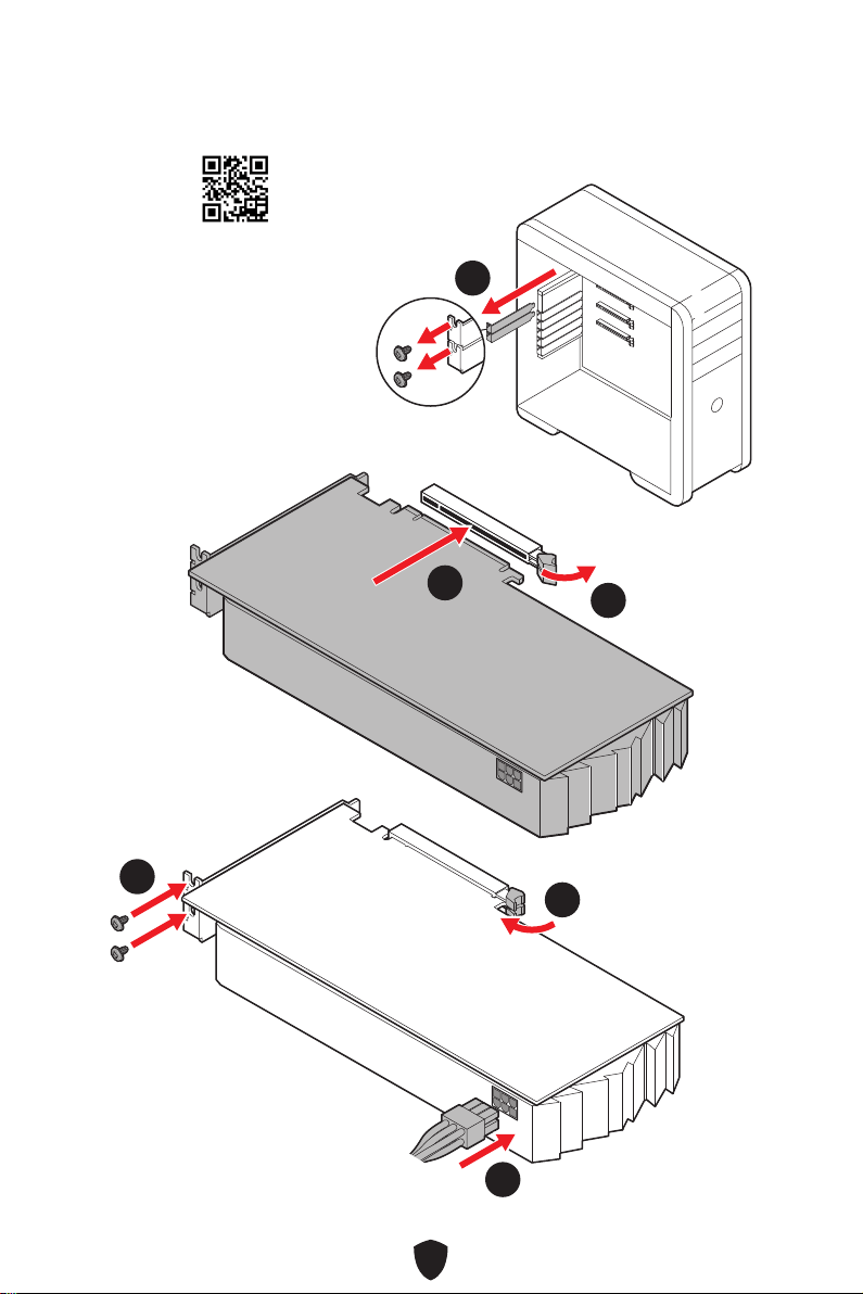
Installing a Graphics Card
http://youtu.be/mG0GZpr9w_A
11
22
33
44
55
66

13
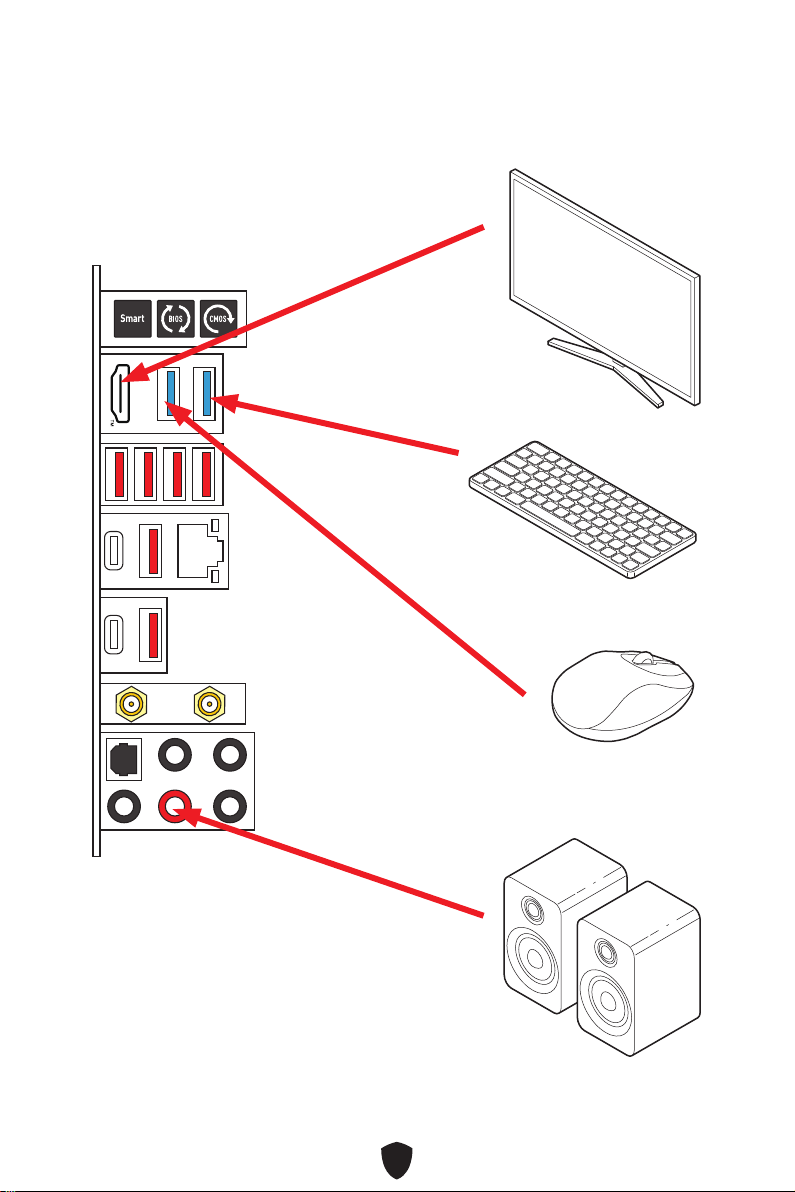
Connecting Peripheral Devices

14
Power On
44
33
11
22

15
Specifications
CPU
Supports 12th/ 13th Gen Intel® Core™ Processors,
Pentium® Gold and Celeron® Processors*
Processor socket LGA1700
* Please go to www.msi.com to get the newest support status as new processors
are released.
Chipset Intel® Z790 Chipset
Memory
4x DDR5 memory slots, supporting up to 128GB*
Supports 1R 5600 MHz (by JEDEC & POR)
Max. overclocking frequency:
• 1DPC 1R Max speed up to 7600+ MHz
• 1DPC 2R Max speed up to 6600+ MHz
• 2DPC 1R Max speed up to 6400+ MHz
• 2DPC 2R Max speed up to 5600+ MHz
Supports Intel® XMP 3.0 OC
Supports Dual-Controller Dual-Channel mode
Supports non-ECC, un-buffered memory
* Please refer to www.msi.com for more information on compatible memory.
Expansion Slots
2x PCIe x16 slots
• PCI_E1 slot (From CPU)
• Supports up to PCIe 5.0 x16*
• PCI_E3 slot (From Z790 chipset)
• Supports up to PCIe 4.0 x4
1x PCIe x1 slot
• PCI_E2 slot (From Z790 chipset)
• Supports up to PCIe 3.0 x1
* PCI_E1 will operate x8 speed when installing M.2 PCIe SSD in the M2_2 slot.
Onboard Graphics
1x HDMI™ 2.1 port with HDR, supports a maximum
resolution of 4K 60Hz*
/
**
* Available only on processors featuring integrated graphics.
** Graphics specifications may vary depending on the CPU installed.
SATA Ports
6x SATA 6Gb/s ports
• SATA5~8 (From Z790 chipset)
• SATA_A1~A2 (From ASM1061)
Continued on next column

16
Continued from previous column
M.2 SSD Slots
5x M.2 slots (Key M)
• M2_1 slot (From CPU)
• Supports up to PCIe 4.0 x4
• Supports 2260/ 2280 storage devices
• M2_2 slot (From CPU)
• Supports up to PCIe 5.0 x4
• Supports 2260/ 2280/ 22110 storage devices
• M2_3 slot (From Z790 chipset)
• Supports up to PCIe 4.0 x4
• Supports 2260/ 2280 storage devices
• M2_4 slot (From Z790 chipset)
• Supports up to PCIe 4.0 x4
• Supports 2260/ 2280 storage devices
• M2_5 slot (From Z790 chipset)
• Supports up to PCIe 4.0 x4
• Support up to SATA 6Gb/s
• Supports 2260/ 2280 storage devices
RAID
Supports RAID 0, RAID 1, RAID 5 and RAID 10 for SATA
storage devices*
Supports RAID 0, RAID 1 , RAID 5 and RAID 10 for M.2
NVMe storage devices
* SATA_A1~A2 do not support RAID function.
Audio
Realtek® ALC4080 Codec
7.1-Channel USB High Performance Audio
Supports up to 32-bit/384kHz playback on front panel
Supports S/PDIF output
LAN 1x Intel® 2.5Gbps LAN controller
Continued on next column

17
Continued from previous column
Wi-Fi & Bluetooth®
Intel® Wi-Fi 6E
The Wireless module is pre-installed in the M.2 (Key-E)
slot
Supports MU-MIMO TX/RX, 2.4GHz/ 5GHz/ 6GHz*(160MHz)
up to 2.4Gbps
Supports 802.11 a/ b/ g/ n/ ac/ ax
Supports Bluetooth® 5.3**, FIPS, FISMA
* Wi-Fi 6E 6GHz may depend on every country’s regulations and will be ready in
Windows 10 build 21H1 and Windows 11.
** Bluetooth 5.3 will be ready in Windows 10 build 21H1 and Windows 11.
Power Connectors
1x 24-pin ATX main power connector
2x 8-pin +12V power connectors
Internal USB
Connectors
1x USB 3.2 Gen 2x2 20Gbps Type-C front panel port (From
Z790 chipset)
1x USB 3.2 Gen 1 5Gbps connector (From Z790 chipset)
• Supports additional 2 USB 3.2 Gen 1 5Gbps ports
2x USB 2.0 connectors (From Hub-GL850G)
• Supports additional 4 USB 2.0 ports
Fan Connectors
1x 4-pin CPU fan connector
1x 4-pin water-pump fan connector
5x 4-pin system fan connectors
System Connectors
1x Front panel audio connector
2x System panel connectors
1x Chassis Intrusion connector
1x TPM module connector
1x Tuning controller connector
1x TBT connector (Supports RTD3)
Jumpers
1x Clear CMOS jumper
1x Safe Boot jumper
Continued on next column

18
Continued from previous column
LED Features
1x EZ LED Control switch
1x 2-Digit Debug Code LED
4x EZ Debug LED
1x 4-pin RGB LED connector
2x 3-pin A-RAINBOW V2 (ARGB Gen2) LED connectors
Back Panel
Connectors
1x Clear CMOS button
1x Flash BIOS button
1x Smart button
2x USB 3.2 Gen 1 5Gbps Type-A ports (From Z790 chipset)
1x HDMI™ port
6x USB 3.2 Gen 2 10Gbps Type-A ports (From Z790 chipset
& GL3590 Hub)
1x LAN (RJ45) jack
1x USB 3.2 Gen 2 10Gbps Type-C port (From Z790 chipset)
1x USB 3.2 Gen 2x2 20Gbps Type-C port (From Asmedia
ASM3242)
2x Wi-Fi antenna connectors
5x Audio jacks
1x Optical S/PDIF out connector
I/O Controller NUVOTON NCT6687D-M Controller Chip
Hardware Monitor
CPU/ System/ Chipset temperature detection
CPU/ System/ Pump fan speed detection
CPU/ System/ Pump fan speed control
Form Factor
ATX Form Factor
9.6 in. x 12 in. (244 mm x 305 mm)
BIOS Features
1x 256 Mb flash
UEFI AMI BIOS
ACPI 6.4, SMBIOS 3.5
Multi-language
Continued on next column

19
Continued from previous column
Software
Drivers
MSI Center
Intel Extreme Tuning Utility
MSI APP Player (BlueStacks)
CPU-Z MSI GAMING
Norton 360 Deluxe
AIDA64 Extreme - MSI Edition
Tile

20
Special Features
MSI Center
• Gaming Mode
• Smart Priority
• Game Highlights
• Mystic Light
• Ambient Link
• Frozr AI Cooling
• User Scenario
• True Color
• Live Update
• Hardware Monitoring
• Super Charger
• Devices Speed Up
• Smart Image Finder
• MSI Companion
Thermal Features
• Double-sided M.2 Shield Frozr
• Extended Heatsink Design Heat-pipe
• K7 MOSFET thermal pad / Extra
choke pad
• Fan headers (CPU + PUMP +
SYSTEM)
Performance
• Core Boost
• VRM Power Design (VCPU / VGT /
AUX)
• Dual CPU Power
• Memory Boost
• Lightning Gen 5 PCI-E / M.2 Slot
• Lightning Gen 4 PCI-E / M.2 Slot
• Front USB Type-C
• Server Grade PCB
• 2oz Copper thickened PCB
DIY Friendly
• PCI-E Steel Armor
• Pre-installed I/O Shield
• Screwless M.2 Shield Frozr
• EZ M.2 Clips
• EZ DEBUG LED
• EZ LED Control
• Smart Button
• Flash BIOS Button
Audio
• Audio Boost 5
RGB Support
• Mystic Light
• Mystic Light Extension (RGB)
• Mystic Light Extension (A-RAINBOW
V2)
• Ambient Link
BIOS
• Click BIOS 5

21
Package Contents
Please check the contents of your motherboard package. It should contain:
Board
• 1x Motherboard
Documentation
• 1x Quick installation guide
• 1x European Union regulatory notice
Application
• 1x USB drive with drivers & utilities
Cables
• 2x SATA 6Gb/s cables
• 1x JRGB extension cable (1 to 2)
• 1x JARGB extension cable
Accessories
• 1x Wi-Fi antenna set
• 4x EZ M.2 clip packages (1 set/pack)
• 1x Cable sticker
Important
There is an ISO file in the supplied USB drive. Please do not delete it accidentally.
For more information on installing drivers, please refer to Installing OS, Drivers &
MSI Center chapter.
If any of the above items are damaged or missing, please contact your retailer.

22
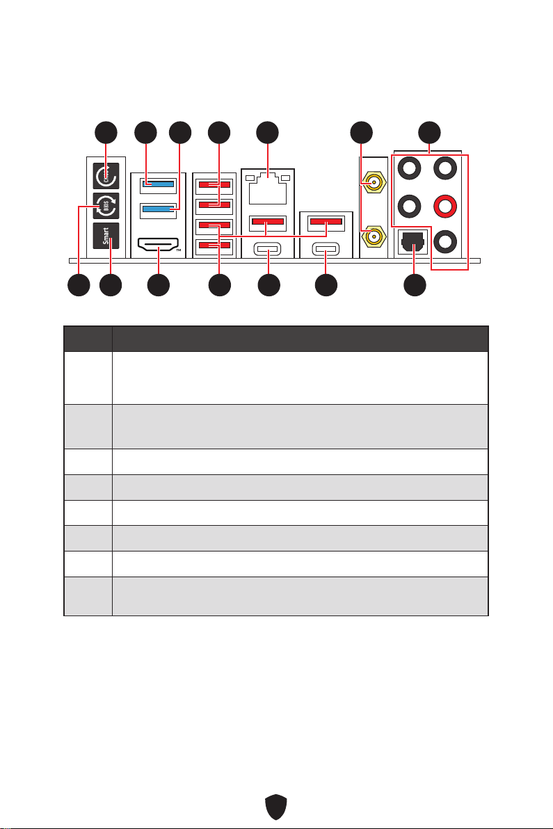
Back Panel Connectors
Item Description
1
Clear CMOS button - Power off your computer. Press and hold the Clear
CMOS button for about 5-10 seconds to reset BIOS to default values.
2
USB 3.2 Gen 1 5Gbps Type-A port (From Z790 chipset)
Flash BIOS port
3 USB 3.2 Gen 1 5Gbps Type-A port (From Z790 chipset)
4 USB 3.2 Gen 2 10Gbps Type-A ports (From Z790 chipset)
5 2.5 Gbps LAN (RJ45) jack
6 Wi-Fi antenna connectors
7 Audio jacks
8
Flash BIOS button - Please refer to page 64 for details about updating BIOS
with Flash BIOS button.
11 77
88 101099 14141313
55 66
12121111
3322 44
23
Item Description
9
Smart button - We provide 4 functions for the smart button to achieve.
Please refer to the BIOS manual for details about selecting the smart
button function.
Reset (default) - press the smart button to reset the system.
Mystic Light on/ off - press the smart button to turn on/ off all the
onboard LEDs. The Mystic Light on/ off function mode is unavailable
when the LED_SW1 (EZ LED Control) switch turns OFF.
Safe Boot - press and hold the smart button and start the system
simultaneously to boot in Safe Boot mode. The system will boot with
default and lower the PCIe (from CPU) mode.
Turbo Fan - press the smart button for all fans to operate full speed or
default speeds.
10
HDMI™ port
11 USB 3.2 Gen 2 10Gbps Type-A ports (From GL3590 Hub)
12 USB 3.2 Gen 2 10Gbps Type-C port (From Z790 chipset)
13 USB 3.2 Gen 2x2 20Gbps Type-C port (From ASM3242)
14 Optical S/PDIF out connector
24
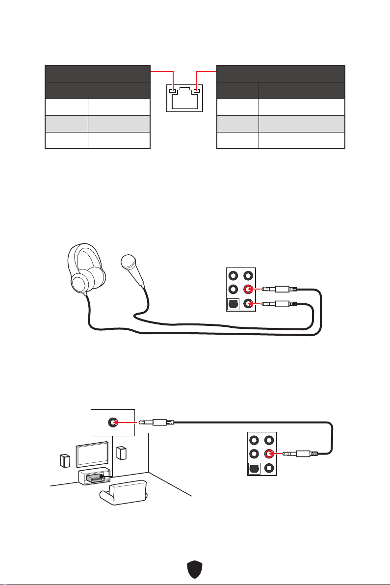
LAN Port LED Status Table
Link/ Activity LED
Status Description
Off No link
Yellow Linked
Blinking Data activity
Speed LED
Status Speed
Off 10 Mbps
Green 100/1000 Mbps
Orange 2.5 Gbps
Audio Jacks Connection
Audio jacks to headphone and microphone diagram
Audio jacks to stereo speakers diagram
AUDIO INPUT
25
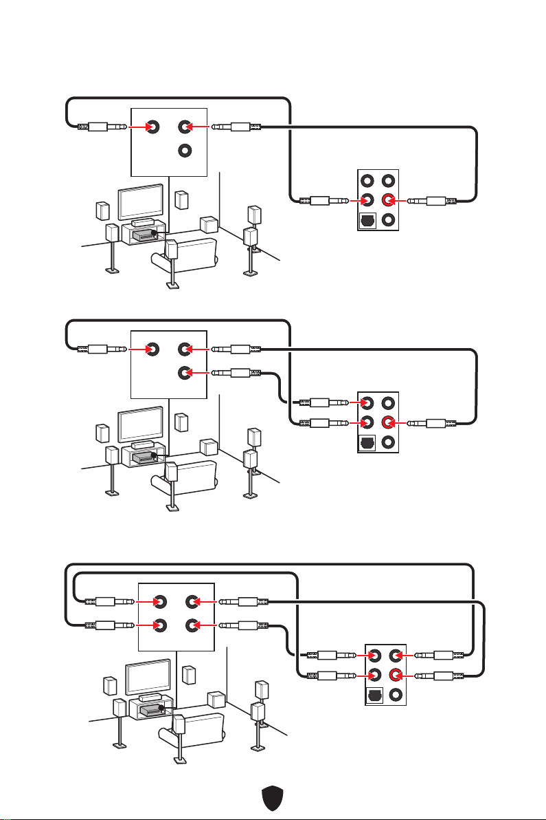
Audio jacks to 7.1-channel speakers diagram
Audio jacks to 4-channel speakers diagram
Audio jacks to 5.1-channel speakers diagram
AUDIO INPUT
Rear Front
Center/
Subwoofer
AUDIO INPUT
Rear Front
Center/
Subwoofer
AUDIO INPUT
Rear Front
Side Center/
Subwoofer
26
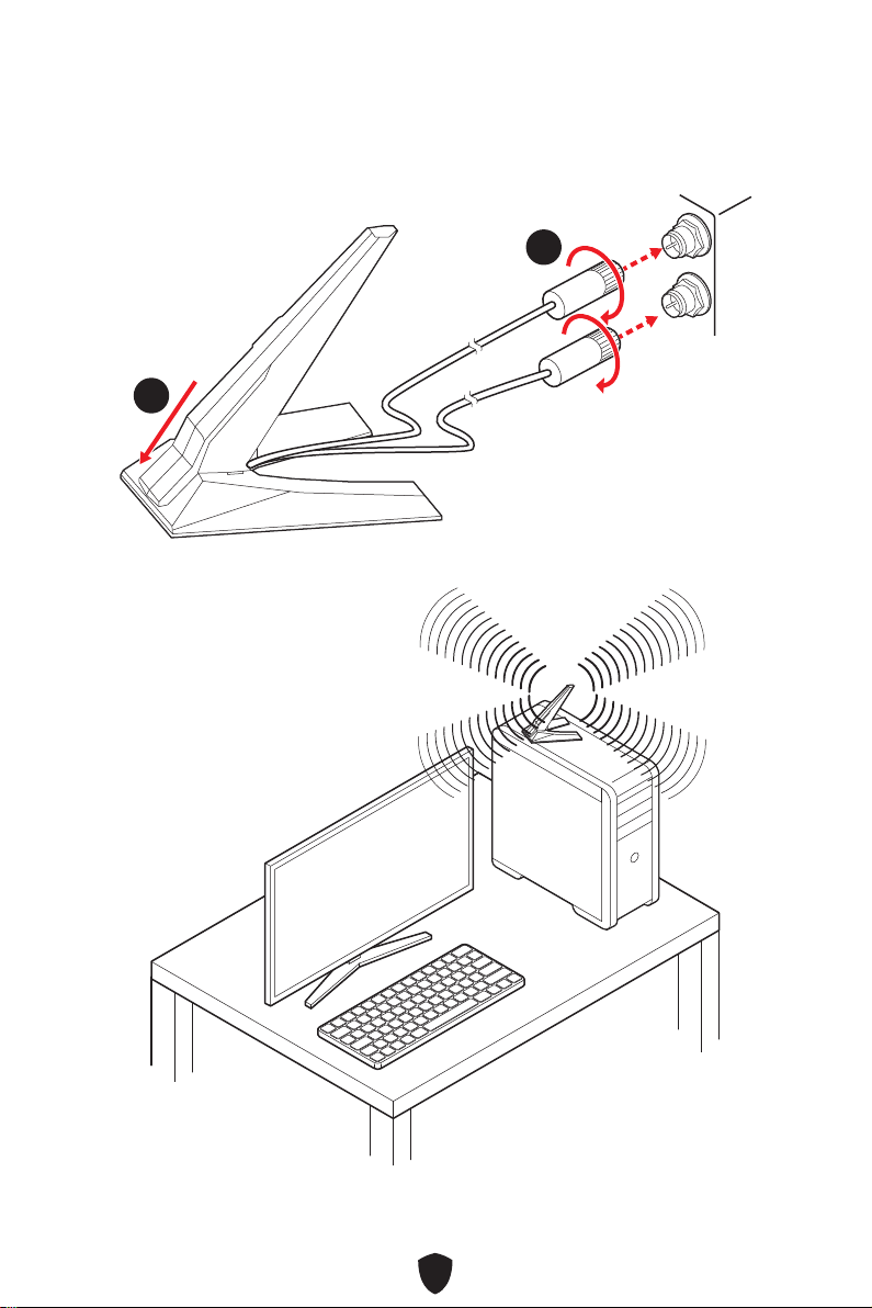
Installing Antennas
1. Combine the antenna with the base.
2. Screw two antenna cables tight to the WiFi antenna connectors as shown.
11
22
3. Place the antenna as high as possible.

27
Overview of Components
CPU_FAN1
PUMP_FAN1
SYS_FAN5
SYS_FAN4
JARGB_V2_2
ATX_PWR1
JUSB4
JUSB3
Processor
Socket
CPU_PWR1
CPU_PWR2
DIMMA2
DIMMB1
DIMMB2
DIMMA1
JCI1
JFP1
JBAT1
JOCFS1
LED_SW1
SYS_FAN3
SYS_FAN2
SYS_FAN1
JDASH1
JPWRLED1
JTBT1
JARGB_V2_1
JRGB1
JAUD1
JUSB2
JUSB1
M2_5
M2_1
M2_2
M2_3
M2_4
PCI_E1
PCI_E2
PCI_E3
JFP2
JTPM1

28
Important
Always unplug the power cord from the power outlet before installing or removing
the CPU.
Please retain the CPU protective cap after installing the processor. MSI will deal
with Return Merchandise Authorization (RMA) requests if only the motherboard
comes with the protective cap on the CPU socket.
When installing a CPU, always remember to install a CPU heatsink. A CPU heatsink
is necessary to prevent overheating and maintain system stability.
Confirm that the CPU heatsink has formed a tight seal with the CPU before booting
your system.
Overheating can seriously damage the CPU and motherboard. Always make sure the
cooling fans work properly to protect the CPU from overheating. Be sure to apply an
even layer of thermal paste (or thermal tape) between the CPU and the heatsink to
enhance heat dissipation.
Whenever the CPU is not installed, always protect the CPU socket pins by covering
the socket with the plastic cap.
If you purchased a separate CPU and heatsink/ cooler, Please refer to the
documentation in the heatsink/ cooler package for more details about installation.
This motherboard is designed to support overclocking. Before attempting to
overclock, please make sure that all other system components can tolerate
overclocking. Any attempt to operate beyond product specifications is not
recommended. MSI® does not guarantee the damages or risks caused by inadequate
operation beyond product specifications.
CPU Socket
Introduction to the LGA1700
CPU
The surface of the LGA1700 CPU has
four notches and a golden triangle to
assist in correctly lining up the CPU for
motherboard placement. The golden
triangle is the Pin 1 indicator.
Distance from the center of the
CPU to the nearest DIMM slot.
50.85 mm

29
DIMM Slots
DIMMA1 DIMMB1
Channel A Channel B
DIMMA2 DIMMB2
Memory module installation recommendation
Important
Always insert memory modules in the DIMMA2 slot first.
To ensure system stability for Dual channel mode, memory modules must be of the
same type, number and density.
Some memory modules may operate at a lower frequency than the marked value
when overclocking due to the memory frequency operates dependent on its Serial
Presence Detect (SPD). Go to BIOS and find the DRAM Frequency to set the memory
frequency if you want to operate the memory at the marked or at a higher frequency.
It is recommended to use a more efficient memory cooling system for full DIMMs
installation or overclocking.
The stability and compatibility of installed memory module depend on installed CPU
and devices when overclocking.
Please refer to www.msi.com for more information on compatible memory.
DIMMA2 DIMMA2
DIMMB2
DIMMA1
DIMMA2
DIMMB1
DIMMB2

30
PCI_E1~3: PCIe Expansion Slots
PCI_E1: PCIe 5.0 x16 (From CPU)
PCI_E2: PCIe 3.0 x1 (From Z790 chipset)
PCI_E3: PCIe 4.0 x4 (From Z790 chipset)
Important
If you install a large and heavy graphics card, you need to use a tool such as MSI
Graphics Card Bolster to support its weight to prevent deformation of the slot.
For a single PCIe x16 expansion card installation with optimum performance, using
the PCI_E1 slot is recommended.
When adding or removing expansion cards, always turn off the power supply and
unplug the power supply power cable from the power outlet. Read the expansion
card’s documentation to check for any necessary additional hardware or software
changes.

31
M2_1~5: M.2 Slots (Key M)
M2_1
M2_2
M2_4
M2_5
M2_3
Important
Intel® RST only supports PCIe M.2 SSD with UEFI ROM.
If your M.2 SSD equips its own heatsink, please remove the M.2 plate or rubber cube
in the M.2 slot before installing M.2 SSD. Do not re-install the heatsink supplied with
your motherboard.
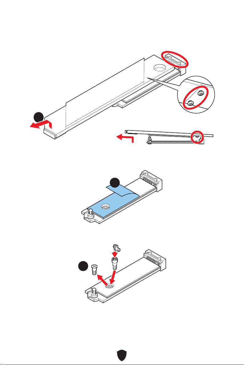
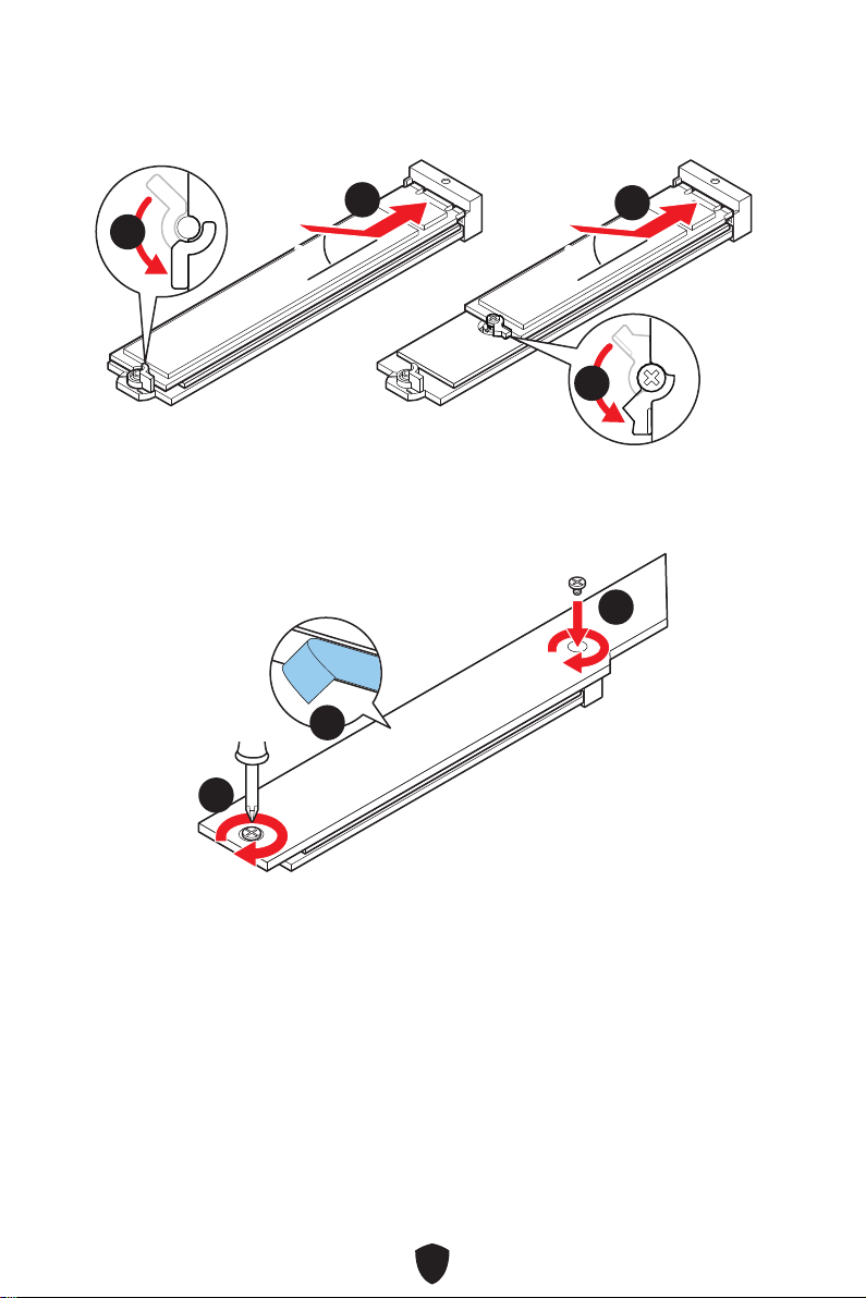
Installing M.2 module into M2_1 slot
1. Press and hold the end button of Screwless M.2 Shield Frozr heatsink.
11
https://youtu.be/J88vcXeLido
Watch the video to learn how to
Install M.2 SSD with Screwless
M.2 Shield Frozr heatsink.
32
2. Slightly lift up the end part of the Screwless M.2 Shield Frozr heatsink and move it
forward to remove the heatsink.
22
3. Remove the protective films from the M.2 thermal pads on the M.2 plate.
33
4. If you install 2260 SSD, remove the screw from the M.2 plate and then install the
supplied EZ M.2 Clip kit on the M.2 plate. Skip this step if you install 2280 SSD.
44
2260 SSD

33
5. Insert your M.2 SSD into the M.2 slot at a 30-degree angle.
6. Rotate the EZ M.2 Clip to fix the M.2 SSD.
30º30º
30º30º
2280 SSD
2260 SSD
66
66
55
55
7. Remove the protective films from the thermal pads under the Screwless M.2 Shield
Frozr heatsink.
8. Align the tenons under Screwless M.2 Shield Frozr heatsink with the notches, and
then put the heatsink back in place.
9. Press the end side of the Screwless M.2 Shield Frozr heatsink down to lock it
completely.
99
88
77

34
Installing M.2 module into M2_2 slot
1. Loosen the screws of M2_1 SHIELD FROZR heatsink and remove the heatsink.
11
11
2. Remove the protective films from the M.2 thermal pads on the M.2 plate.
22
3. Remove or exchange the screws according to your SSD length. Skip this step, if you
install 2280 SSD.
33
33
22110 SSD
2260 SSD
35
4. Insert your M.2 SSD into the M.2 slot at a 30-degree angle.
5. Rotate the EZ M.2 Clip to fix the M.2 SSD.
30º30º
30º30º
22110 SSD
2280 SSD
2260 SSD
44
44
55
55
6. Remove the protective films from the thermal pads under the M.2 Shield Frozr
heatsink.
7. M.2 SHIELD FROZR heatsink back in place and secure it.
66
77
77

36
Installing M.2 module into M2_3/ M2_4/ M2_5 slot
1. Loosen the screws of M.2 SHIELD FROZR heatsink.
11
11
11
11
2. Remove the protective films from the M.2 thermal pads on the M.2 plate.
22
3. If you install 2260 SSD, remove the screw from the M.2 plate and then install the
supplied EZ M.2 Clip kit on the M.2 plate. Skip this step if you install 2280 SSD.
33
2260 SSD

37
4. Insert your M.2 SSD into the M.2 slot at a 30-degree angle.
5. Rotate the EZ M.2 Clip to fix the M.2 SSD.
30º30º
30º30º
2280 SSD
2260 SSD
55
44
44
55
6. Remove the protective films from the thermal pads under the M.2 Shield Frozr
heatsink.
7. Put the M.2 Shield Frozr heatsink back in place and secure it.
66
77
77 77
77
38
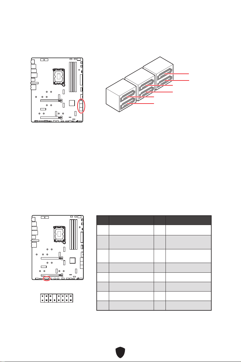
SATA5~8 & SATA_A1~A2: SATA 6Gb/s Connectors
These connectors are SATA 6Gb/s interface ports. Each connector can connect to one
SATA device.
SATA5
SATA7
SATA_A1
SATA6
SATA8
SATA_A2
Important
Please do not fold the SATA cable at a 90-degree angle. Data loss may result during
transmission otherwise.
SATA cables have identical plugs on either sides of the cable. However, it is
recommended that the flat connector be connected to the motherboard for space
saving purposes.
JTBT1: Thunderbolt Add-on Card Connector
This connector allows you to connect the add-on Thunderbolt I/O card.
1
2 16
15
Pin Signal Name Pin Signal Name
1 TBT_FORCE_PWR 2 TBT_S0IX_ENTRY_REQ
3
TBT_CIO_PLUG_
EVENT#
4 TBT_S0IX_ENTRY_ACK
5 SLP_S3#_TBT 6
TBT_PSON_
OVERRIDE_N
7 SLP_S5#_TBT 8 No Pin
9 Ground 10 SMBCLK_VSB
11 DG_PEWAKE# 12 SMBDATA_VSB
13 TBT_RTD3_PWR_EN 14 Ground
15 TBT_CARD_DET_R# 16 PD_IRQ#

39
JAUD1: Front Audio Connector
This connector allows you to connect audio jacks on the front panel.
1
2 10
9
Pin Signal Name Pin Signal Name
1 MIC L 2 Ground
3 MIC R 4 NC
5 Head Phone R 6 MIC Detection
7 SENSE_SEND 8 No Pin
9 Head Phone L 10 Head Phone Detection
JFP1, JFP2: Front Panel Connectors
The JFP1 connector controls the power on, power reset, and the LEDs on your PC
case/ chassis. Power Switch/ Reset Switch headers allow you to connect power
button/ reset button. Power LED header connects to LED light on the PC case, and
HDD LED header indicates the activity of the hard disk. The JFP2 connector is for
Buzzer and Speaker. To connect the cables from PC case to the right pins, please
refer to the following images below.
1
2 10
9
Power LED
Reserved
Power Switch
JFP1
Reset SwitchHDD LED
1
JFP2
Buzzer
Speaker
Important
Please note that Power LED and HDD LED have positive and negative connection,
you need to link up the cable to the corresponding positive and negative port on the
motherboard. Otherwise, LEDs won’t work properly.

40
Important
Make sure that all the power cables are securely connected to a proper ATX power
supply to ensure stable operation of the motherboard.
CPU_PWR1~2, ATX_PWR1: Power Connectors
These connectors allow you to connect an ATX power supply.
CPU_PWR1~2
Pin Signal Name Pin Signal Name
1 Ground 2 Ground
3 Ground 4 Ground
5 +12V 6 +12V
7 +12V 8 +12V
ATX_PWR1
Pin Signal Name Pin Signal Name
1 +3.3V 2 +3.3V
3 Ground 4 +5V
5 Ground 6 +5V
7 Ground 8 PWR OK
9 5VSB 10 +12V
11 +12V 12 +3.3V
13 +3.3V 14 -12V
15 Ground 16 PS-ON#
17 Ground 18 Ground
19 Ground 20 Res
21 +5V 22 +5V
23 +5V 24 Ground
5
4 1
8
CPU_PWR1~2
24
131
12
ATX_PWR1

41
JCI1: Chassis Intrusion Connector
This connector allows you to connect the chassis intrusion switch cable.
Normal
(default)
Trigger the chassis
intrusion event
Using chassis intrusion detector
1. Connect the JCI1 connector to the chassis intrusion switch/ sensor on the chassis.
2. Close the chassis cover.
3. Go to BIOS > SETTINGS > Security > Chassis Intrusion Configuration.
4. Set Chassis Intrusion to Enabled.
5. Press F10 to save and exit and then press the Enter key to select Yes.
6. Once the chassis cover is opened again, a warning message will be displayed on
screen when the computer is turned on.
Resetting the chassis intrusion warning
1. Go to BIOS > SETTINGS > Security > Chassis Intrusion Configuration.
2. Set Chassis Intrusion to Reset.
3. Press F10 to save and exit and then press the Enter key to select Yes.
JDASH1 : Tuning Controller connector
This connector is used to connect an optional Tuning Controller module.
Pin Signal Name Pin Signal Name
1 No Pin 2 NC
3
MCU_SMB_SCL_M
4 MCU_SMB_SDA_M
5 VCC5 6 Ground
1
2
5
6

42
JUSB3: USB 3.2 Gen 1 Connector
This connector allows you to connect USB 3.2 Gen 1 5Gbps ports on the front panel.
Important
Note that the Power and Ground pins must be connected correctly to avoid possible
damage.
JUSB4: USB 3.2 Gen 2x2 Type-C front panel Connector
This connector allows you to connect USB 3.2 Gen 2x2 20Gbps Type-C connector on
the front panel. The connectors possess a foolproof design. When you connect the
cable, be sure to connect it with the corresponding orientation.
JUSB4
USB Type-C Cable
USB Type-C port on
the front panel
Pin Signal Name Pin Signal Name
1 Power 2 USB3_RX_DN
3 USB3_RX_DP 4 Ground
5 USB3_TX_C_DN 6 USB3_TX_C_DP
7 Ground 8 USB2.0-
9 USB2.0+ 10 Ground
11 USB2.0+ 12 USB2.0-
13 Ground 14 USB3_TX_C_DP
15 USB3_TX_C_DN 16 Ground
17 USB3_RX_DP 18 USB3_RX_DN
19 Power 20 No Pin
1
10 11
20

43
JUSB1~2: USB 2.0 Connectors
These connectors allow you to connect USB 2.0 ports on the front panel.
Important
Note that the VCC and Ground pins must be connected correctly to avoid possible
damage.
In order to recharge your iPad, iPhone and iPod through USB ports, please install
MSI Center utility.
JTPM1: TPM Module Connector
This connector is for TPM (Trusted Platform Module). Please refer to the TPM security
platform manual for more details and usages.
Pin Signal Name Pin Signal Name
1 VCC 2 VCC
3 USB0- 4 USB1-
5 USB0+ 6 USB1+
7 Ground 8 Ground
9 No Pin 10 NC
1
2 10
9
Pin Signal Name Pin Signal Name
1 SPI Power 2 SPI Chip Select
3
Master In Slave Out
(SPI Data)
4
Master Out Slave In
(SPI Data)
5 Reserved 6 SPI Clock
7 Ground 8 SPI Reset
9 Reserved 10 No Pin
11 Reserved 12 Interrupt Request
1
2 12
11

44
CPU_FAN1, PUMP_FAN1, SYS_FAN1~5: Fan Connectors
Fan connectors can be classified as PWM (Pulse Width Modulation) Mode or DC Mode.
PWM Mode fan connectors provide constant 12V output and adjust fan speed with
speed control signal. DC Mode fan connectors control fan speed by changing voltage.
The auto mode fan connectors can automatically detect PWM and DC mode.
You can control fans in BIOS> HARDWARE MONITOR panel. It allows you to set DC
or PWM to your fan type. Check the Smart Fan Mode, the fan speed will change
according to the CPU or system temperature. Uncheck the Smart Fan Mode, the fan
will spin at maximum speed.
Important
Make sure fans are working properly after switching the PWM/ DC mode.
CPU_FAN1
SYS_FAN2
SYS_FAN1
SYS_FAN3
PUMP_FAN1
SYS_FAN5
SYS_FAN4
1
PWM Mode pin definition
Pin Signal Name Pin Signal Name
1 Ground 2 +12V
3 Sense 4 Speed Control Signal
DC Mode pin definition
Pin Signal Name Pin Signal Name
1 Ground 2 Voltage Control
3 Sense 4 NC
Fan connector specifications
Connector Default fan mode Max. current Max. power
CPU_FAN1 Auto mode 2A 24W
PUMP_FAN1 PWM mode 3A 36W
SYS_FAN1~5 DC mode 1A 12W
1

45
JBAT1: Clear CMOS (Reset BIOS) Jumper
There is CMOS memory onboard that is external powered from a battery located on
the motherboard to save system configuration data. If you want to clear the system
configuration, set the jumpers to clear the CMOS memory.
If the CMOS battery is out of charge, the time in the BIOS will be reset and the data of
system configuration will be lost. In this case, you need to replace the CMOS battery.
Keep Data
(default)
Clear CMOS/
Reset BIOS
Resetting BIOS to default values
1. Power off the computer and unplug the power cord.
2. Use a jumper cap to short JBAT1 for about 5-10 seconds.
3. Remove the jumper cap from JBAT1.
4. Plug the power cord and Power on the computer.
Replacing CMOS battery
1. Unplug the battery wire from the BAT1 connector and
remove the battery.
2. Connect the new CR2032 battery with wire to the
BAT1 connector.

46
Important
The JRGB connector supports up to 2 meters continuous 5050 RGB LED strips
(12V/G/R/B) with the maximum power rating of 3A (12V).
Always turn off the power supply and unplug the power cord from the power outlet
before installing or removing the RGB LED strip.
Please use MSI’s software to control the extended LED strip.
JRGB1: RGB LED connector
The JRGB connector allows you to connect the 5050 RGB LED strips 12V.
1
G
R
B
JRGB connector
JRGB extension cable
5050 RGB LED strips 12V
RGB LED Strip Connection
1
1
G
R
B
JRGB connector
System fan connector
RGB LED Fan Connection
RGB LED fan
Pin Signal Name Pin Signal Name
1 +12V 2 G
3 R 4 B
1

47
JARGB_V2_1~2: A-RAINBOW V2 (ARGB Gen2) LED connectors
The JARGB_V2 connectors allow you to connect the ARGB Gen2 and the ARGB-based
LED strips. The JARGB_V2 connector supports up to 240 individually addressable RGB
LEDs with maximum power rating of 3A (5V).
Pin Signal Name Pin Signal Name
1 +5V 2 Data
3 No Pin 4 Ground
1
1
1
1
1
D
+5V
JARGB_V2 connector
JARGB_V2 connector
System Fan connector
JARGB extension cable
ARGB/ ARGB Gen2 LED strip
Addressable RGB LED Strip Connection
Addressable RGB LED Fan Connection
ARGB/ ARGB Gen2 LED Fan

48
CAUTION
Do not connect the wrong type of LED strips. The JRGB connector and the JARGB_V2
connector provide different voltages, and connecting the ARGB 5V LED strip to the
JRGB connector will result in damage to the LED strip.
Important
If you connect the ARGB Gen1 and ARGB Gen2 LED strips into the same connector, it
may cause some issues. Please do not mix the ARGB Gen1 LED and the ARGB Gen2
LED strips together.
It is recommended that you install LED strips with the same specification to achieve
the best effects.
Always turn off the power supply and unplug the power cord from the power outlet
before installing or removing the addressable RGB LED strip.
Please use MSI’s software to control the extended LED strip.
Normal
(default)
Boot with the saved
BIOS settings.
Enabled
Apply the BIOS default
settings and lower PCIe
(from CPU) mode for
Safe Boot
JOCFS1: Safe Boot Jumper
This jumper is used for Safe Boot. Once enabled, the system will boot with default
settings and lower PCIe (from CPU) mode.
49
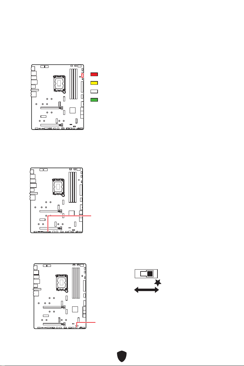
EZ Debug LED
These LEDs indicate the debug status of the motherboard.
CPU - indicates CPU is not detected or fail.
DRAM - indicates DRAM is not detected or fail.
VGA - indicates GPU is not detected or fail.
BOOT - indicates the booting device is not detected or fail.
Onboard LEDs
JPWRLED1: LED power input
This connector is used by retailers to demonstrate onboard LED lights.
JPWRLED1 - LED power input
LED_SW1: EZ LED Control
This switch is used to switch on/ off all the LEDs of motherboard.
LED_SW1
LED_OFF
LED_ON
(Default)

50
Debug Code LED
The Debug Code LED displays progress and error codes during and after POST. Refer
to the Debug Code LED table for details.
Boot Phases
Security (SEC) – initial low-level initialization
Pre-EFI Initialization (PEI) – memory initialization
Driver Execution Environment (DXE) – main hardware initialization
Boot Device Selection (BDS) – system setup, pre-OS user interface & selecting a
bootable device (CD/DVD, HDD, USB, Network, Shell, …)
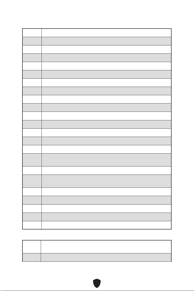
Debug Code LED Table
SEC Progress Codes
01 Power on. Reset type detection (soft/hard)
02 AP initialization before microcode loading
03 System Agent initialization before microcode loading
04 PCH initialization before microcode loading
06 Microcode loading
07 AP initialization after microcode loading
08 System Agent initialization after microcode loading
09 PCH initialization after microcode loading
0B Cache initialization
SEC Error Codes
0C - 0D Reserved for future AMI SEC error codes
0E Microcode not found
0F Microcode not loaded
Hexadecimal Character Table
Hexadecimal 0 1 2 3 4 5 6 7
LED display
Hexadecimal 8 9 A B C D E F
LED display
51
PEI Progress Codes
10 PEI Core is started
11 Pre-memory CPU initialization is started
12 - 14 Pre-memory CPU initialization (CPU module specific)
15 Pre-memory System Agent initialization is started
16 - 18 Pre-Memory System Agent initialization (System Agent module specific)
19 Pre-memory PCH initialization is started
1A - 1C Pre-memory PCH initialization (PCH module specific)
2B Memory initialization. Serial Presence Detect (SPD) data reading
2C Memory initialization. Memory presence detection
2D Memory initialization. Programming memory timing information
2E Memory initialization. Configuring memory
2F Memory initialization (other)
31 Memory Installed
32 CPU post-memory initialization is started
33 CPU post-memory initialization. Cache initialization
34 CPU post-memory initialization. Application Processor(s) (AP)
initialization
35 CPU post-memory initialization. Boot Strap Processor (BSP) selection
36 CPU post-memory initialization. System Management Mode (SMM)
initialization
37 Post-Memory System Agent initialization is started
38 - 3A Post-Memory System Agent initialization (System Agent module specific)
3B Post-Memory PCH initialization is started
3C - 3E Post-Memory PCH initialization (PCH module specific)
4F DXE IPL is started
PEI Error Codes
50 Memory initialization error. Invalid memory type or incompatible
memory speed
51 Memory initialization error. SPD reading has failed
52
52 Memory initialization error. Invalid memory size or memory modules do
not match
53 Memory initialization error. No usable memory detected
54 Unspecified memory initialization error
55 Memory not installed
56 Invalid CPU type or Speed
57 CPU mismatch
58 CPU self test failed or possible CPU cache error
59 CPU micro-code is not found or micro-code update is failed
5A Internal CPU error
5B Reset PPI is not available
5C - 5F Reserved for future AMI error codes
DXE Progress Codes
60 DXE Core is started
61 NVRAM initialization
62 Installation of the PCH Runtime Services
63 CPU DXE initialization is started
64 - 67 CPU DXE initialization (CPU module specific)
68 PCI host bridge initialization
69 System Agent DXE initialization is started
6A System Agent DXE SMM initialization is started
6B - 6F System Agent DXE initialization (System Agent module specific)
70 PCH DXE initialization is started
71 PCH DXE SMM initialization is started
72 PCH devices initialization
73 - 77 PCH DXE Initialization (PCH module specific)
78 ACPI module initialization
79 CSM initialization
7A - 7F Reserved for future AMI DXE codes

53
90 Boot Device Selection (BDS) phase is started
91 Driver connecting is started
92 PCI Bus initialization is started
93 PCI Bus Hot Plug Controller Initialization
94 PCI Bus Enumeration 32
95 PCI Bus Request Resources
96 PCI Bus Assign Resources
97 Console Output devices connect
98 Console input devices connect
99 Super IO Initialization
9A USB initialization is started
9B USB Reset
9C USB Detect
9D USB Enable
9E -9F Reserved for future AMI codes
A0 IDE initialization is started
A1 IDE Reset
A2 IDE Detect
A3 IDE Enable
A4 SCSI initialization is started
A5 SCSI Reset
A6 SCSI Detect
A7 SCSI Enable
A8 Setup Verifying Password
A9 Start of Setup
AB Setup Input Wait
AD Ready To Boot event
AE Legacy Boot event
AF Exit Boot Services event
54
B0 Runtime Set Virtual Address MAP Begin
B1 Runtime Set Virtual Address MAP End
B2 Legacy Option ROM Initialization
B3 System Reset
B4 USB hot plug
B5 PCI bus hot plug
B6 Clean-up of NVRAM
B7 Configuration Reset (reset of NVRAM settings)
B8 - BF Reserved for future AMI codes
DXE Error Codes
D0 CPU initialization error
D1 System Agent initialization error
D2 PCH initialization error
D3 Some of the Architectural Protocols are not available
D4 PCI resource allocation error. Out of Resources
D5 No Space for Legacy Option ROM
D6 No Console Output Devices are found
D7 No Console Input Devices are found
D8 Invalid password
D9 Error loading Boot Option (LoadImage returned error)
DA Boot Option is failed (StartImage returned error)
DB Flash update is failed
DC Reset protocol is not available
S3 Resume Progress Codes
E0 S3 Resume is stared (S3 Resume PPI is called by the DXE IPL)
E1 S3 Boot Script execution
E2 Video repost
E3 OS S3 wake vector call
55
E4 - E7 Reserved for future AMI progress codes
S3 Resume Error Codes
E8 S3 Resume Failed
E9 S3 Resume PPI not Found
EA S3 Resume Boot Script Error
EB S3 OS Wake Error
EC - EF Reserved for future AMI error codes
Recovery Progress Codes
F0 Recovery condition triggered by firmware (Auto recovery)
F1 Recovery condition triggered by user (Forced recovery)
F2 Recovery process started
F3 Recovery firmware image is found
F4 Recovery firmware image is loaded
F5 - F7 Reserved for future AMI progress codes
Recovery Error Codes
F8 Recovery PPI is not available
F9 Recovery capsule is not found
FA Invalid recovery capsule
FB - FF Reserved for future AMI error codes
ACPI States Codes
The following codes appear after booting and the operating system into ACPI modes.
01 System is entering S1 sleep state
02 System is entering S2 sleep state
03 System is entering S3 sleep state
04 System is entering S4 sleep state
05 System is entering S5 sleep state
10 System is waking up from the S1 sleep state
20 System is waking up from the S2 sleep state

56
30 System is waking up from the S3 sleep state
40 System is waking up from the S4 sleep state
AC System has transitioned into ACPI mode. Interrupt controller is in PIC
mode.
AA System has transitioned into ACPI mode. Interrupt controller is in APIC
mode.
CPU Temperature
00 - 99 Displays current CPU temperature after the system has fully booted into
the OS.

57
Installing OS, Drivers & MSI Center
Please download and update the latest utilities and drivers at www.msi.com
Installing Windows 10/ Windows 11
1. Power on the computer.
2. Insert the Windows 10/ Windows 11 installation disc/USB into your computer.
3. Press the Restart button on the computer case.
4. Press F11 key during the computer POST (Power-On Self Test) to get into Boot
Menu.
5. Select the Windows 10/ Windows 11 installation disc/USB from the Boot Menu.
6. Press any key if screen shows Press any key to boot from CD or DVD... message. If
not, please skip this step.
7. Follow the instructions on the screen to install Windows 10/ Windows 11.

58
Installing Drivers with MSI Driver Utility Installer
Important
Some new network chips have not been natively supported by Windows 10/ Windows
11. It is recommended that the LAN driver be installed before installing drivers with
MSI Driver Utility Installer. Please refer to www.msi.com to install the LAN driver for
your motherboard.
The MSI Driver Utility Installer will only pop up once. If you cancel or close it during
the process, please refer to the Live Update chapter of the MSI Center manual to
install the drivers. You can also go to www.msi.com to search your motherboard and
download the drivers.
MSI Driver Utility Installer needs to be installed over the internet.
1. Start up your computer in Windows 10/ Windows 11.
2. Select Start > Settings > Windows Update, and then select Check for updates.
3. MSI Driver Utility Installer will pop up automatically.
4. Select the I have read and agree to the MSI Terms of Use check box, and then click
Next.
59
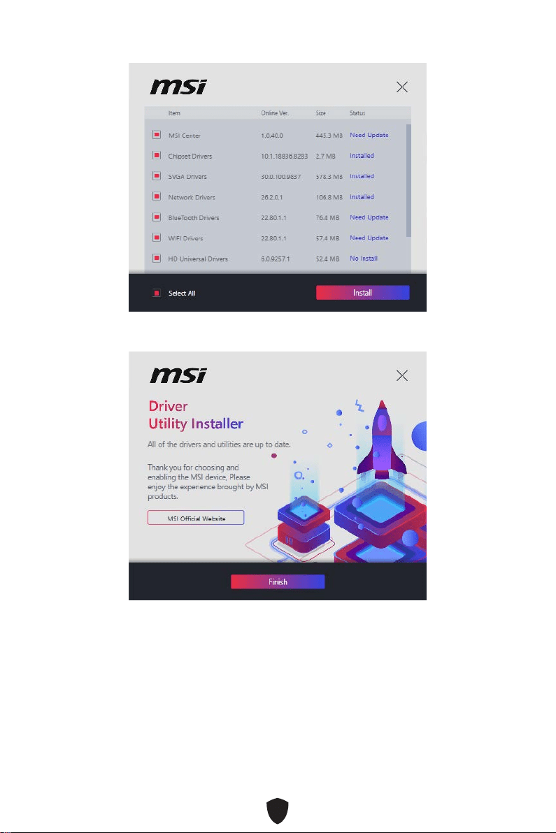
5. Check the Select All checkbox in the lower-left corner and click Install to install
MSI Center and drivers. The installation progress will be shown at the bottom.
6. Once the progress has completed, click Finish.
60
Installing Drivers with USB Drive
1. Start up your computer in Windows 10/ Windows 11.
2. Insert MSI® USB Drive into the USB port.
3. You can see a Disc Image file which contains drivers and utilities in the USB drive.
Double-click the file to open it.
4. Execute an application file named DVDSetup.
5. The installer will find and list all necessary drivers in the Drivers/Software tab.
6. Click the Install button in the lower-right corner of the window.
7. The drivers installation will then be in progress, after it has finished it will prompt
you to restart.
8. Click OK button to finish.
9. Restart your computer.
MSI Center
MSI Center is an application that helps you easily optimize game settings and
smoothly use content creation softwares. It also allows you to control and synchronize
LED light effects on PCs and other MSI products. With MSI Center, you can customize
ideal modes, monitor system performance, and adjust fan speed.
MSI Center User Guide
If you would like to know more information about MSI Center, please refer to
http://download.msi.com/manual/mb/MSICENTER.pdf
or scan the QR code to access.
Important
Functions may vary depending on the product you have.

61
UEFI BIOS
MSI UEFI BIOS is compatible with UEFI (Unified Extensible Firmware Interface)
architecture. UEFI has many new functions and advantages that traditional BIOS
cannot achieve, and it will completely replace BIOS in the future. The MSI UEFI
BIOS uses UEFI as the default boot mode to take full advantage of the new chipset’s
capabilities.
Important
The term BIOS in this user guide refers to UEFI BIOS unless otherwise noted.
UEFI advantages
Fast booting - UEFI can directly boot the operating system and save the BIOS self-
test process. And also eliminates the time to switch to CSM mode during POST.
Supports for hard drive partitions larger than 2 TB.
Supports more than 4 primary partitions with a GUID Partition Table (GPT).
Supports unlimited number of partitions.
Supports full capabilities of new devices - new devices may not provide backward
compatibility.
Supports secure startup - UEFI can check the validity of the operating system to
ensure that no malware tampers with the startup process.
Incompatible UEFI cases
32-bit Windows operating system - this motherboard supports only Windows 10/
Windows 11 64-bit operating system.
Older graphics card - the system will detect your graphics card. If you use older
graphics cards, it may display a warning message There is no GOP (Graphics Output
protocol) support detected in this graphics card.
Important
We recommend that you replace it with a graphics card supporting GOP/UEFI or use
CPU with integrated graphics for having normal function.
How to check the BIOS mode?
1. Power on your computer.
2. Press Delete key, when the Press DEL key to enter Setup Menu, F11 to enter Boot
Menu message appears on the screen during the boot process.
3. After entering the BIOS, you can check the BIOS Mode at the top of the screen.
BIOS Mode: UEFI

62
BIOS Setup
The default settings offer the optimal performance for system stability in normal
conditions. You should always keep the default settings to avoid possible system
damage or failure booting unless you are familiar with BIOS.
Important
BIOS items are continuously update for better system performance. Therefore,
the description may be slightly different from the latest BIOS and should be for
reference only. You could also refer to the HELP information panel for BIOS item
description.
The BIOS screens, options and settings will vary depending on your system.
Entering BIOS Setup
Press Delete key, when the Press DEL key to enter Setup Menu, F11 to enter Boot
Menu message appears on the screen during the boot process.
Function key
F1: General Help list
F2: Add/ Remove a favorite item
F3: Enter Favorites menu
F4: Enter CPU Specifications menu
F5: Enter Memory-Z menu
F6: Load optimized defaults
F7: Switch between Advanced mode and EZ mode
F8: Load Overclocking Profile
F9: Save Overclocking Profile
F10: Save Change and Reset*
F12: Take a screenshot and save it to USB flash drive (FAT/ FAT32 format only).
Ctrl+F: Enter Search page
* When you press F10, a confirmation window appears and it provides the modification
information. Select between Yes or No to confirm your choice.
BIOS User Guide
If you’d like to know more instructions on setting up the BIOS, please refer to
https://download.msi.com/archive/mnu_exe/mb/Intel700BIOS.pdf
or scan the QR code to access.
Important
Functions may vary depending on the product you have.

63
Resetting BIOS
You might need to restore the default BIOS setting to solve certain problems. There
are several ways to reset BIOS:
Go to BIOS and press F6 to load optimized defaults.
Short the Clear CMOS jumper on the motherboard.
Press the Clear CMOS button on the rear I/O panel.
Important
Be sure the computer is off before clearing CMOS data. Please refer to the Clear
CMOS jumper/ button section for resetting BIOS.
Updating BIOS
Updating BIOS with M-FLASH
Before updating:
Please download the latest BIOS file that matches your motherboard model from MSI
website. And then save the BIOS file into the USB flash drive.
Updating BIOS:
1. Switch to the target BIOS ROM by Multi-BIOS switch. Please skip this step if your
motherboard doesn’t has this switch.
2. Insert the USB flash drive that contains the update file into the USB port.
3. Please refer the following methods to enter flash mode.
• Reboot and press Ctrl + F5 key during POST and click on Yes to reboot the system.
Press <Ctrl+F5> to activate M-Flash for BIOS update.
• Reboot and press Del key during POST to enter BIOS. Click the M-FLASH button
and click on Yes to reboot the system.
4. Select a BIOS file to perform the BIOS update process.
5. When prompted click on Yes to start recovering BIOS.
6. After the flashing process is 100% completed, the system will reboot automatically.

64
Updating the BIOS with MSI Center
Before updating:
Make sure the LAN driver is already installed and the internet connection is set
properly.
Please close all other application software before updating the BIOS.
To update BIOS:
1. Install and launch MSI Center and go to Support page.
2. Select Live Update and click on Advance button.
3. Select the BIOS file and click on Install button.
4. The installation reminder will appear, then click the Install button on it.
5. The system will automatically restart to update BIOS.
6. After the flashing process is 100% completed, the system will restart
automatically.
Updating BIOS with Flash BIOS Button
1. Please download the latest BIOS file that matches your motherboard model from
the MSI® website.
2. Rename the BIOS file to MSI.ROM, and save it to the root of the USB storage device.
3. Connect the power supply to CPU_PWR1 and ATX_PWR1. (No need to install CPU
and memory.)
4. Plug the USB storage device that contains the MSI.ROM file into the Flash BIOS
Port on the rear I/O panel.
5. Press the Flash BIOS Button to flash BIOS, and the LED starts flashing.
6. The LED will be turned off when the process is completed.

1
Inhalt
Schnellstart .......................................................................................................3
Spezifikationen ................................................................................................15
Besondere Funktionen ....................................................................................20
Lieferumfang ...................................................................................................21
Anschlüsse auf der Rückseite .........................................................................22
LAN Port LED Zustandstabelle ............................................................................ 24
Audiobuchsen ....................................................................................................... 24
Antennen installieren ........................................................................................... 26
Übersicht der Komponenten ...........................................................................27
CPU Sockel ........................................................................................................... 28
DIMM Steckplätze ................................................................................................. 29
PCI_E1~3: PCIe Erweiterungssteckplätze ........................................................... 30
M2_1~5: M.2 Steckplätze (Key M) ........................................................................ 31
SATA5~8 & SATA_A1~A2: SATA 6Gb/s Anschlüsse ............................................. 38
JTBT1: Anschluss für Thunderbolt-Erweiterungskarte ...................................... 38
JAUD1: Audioanschluss des Frontpanels ............................................................ 39
JFP1, JFP2: Frontpanel-Anschlüsse ................................................................... 39
CPU_PWR1~2, ATX_PWR1: Stromanschlüsse .................................................... 40
JCI1: Gehäusekontaktanschluss .......................................................................... 41
JDASH1: Tuning Controller-Anschluss................................................................ 41
JUSB4: USB 3.2 Gen 2 2x2 Typ-C Anschluss an der Vorderseite ........................ 42
JUSB3: USB 3.2 Gen 1 Anschluss ........................................................................ 42
JUSB1~2: USB 2.0 Anschlüsse ............................................................................. 43
JTPM1: TPM Anschluss ........................................................................................ 43
CPU_FAN1, PUMP_FAN1, SYS_FAN1~5: Stromanschlüsse für Lüfter .............. 44
JBAT1: Clear CMOS Steckbrücke (Reset BIOS) ................................................... 45
........................................................................................... 45
JRGB1: RGB LED Anschluss ................................................................................ 46
JARGB_V2_1~2: A-RAINBOW V2 (ARGB Gen2) LED Anschlüsee ........................ 47
JOCFS1: Steckbrücke für sicheren Start ............................................................. 48
Onboard LEDs ..................................................................................................49
EZ DEBUG LED ..................................................................................................... 49
Deutsch

2
JPWRLED1: LED Stromzufuhr ............................................................................. 49
LED_SW1: EZ LED Steuerung .............................................................................. 49
Debug-Code-LED ................................................................................................. 50
Boot-Phasen ......................................................................................................... 50
Debug-Code-LED-Tabelle .................................................................................... 50
Installation von OS, Treibern & MSI Center ....................................................57
Installation von Treibern mit dem MSI Driver Utility Installer ............................ 58
MSI Center ............................................................................................................ 60
UEFI BIOS .........................................................................................................61
BIOS Setup ............................................................................................................ 62
Reset des BIOS ..................................................................................................... 63
Aktualisierung des BIOS ....................................................................................... 63
3
Schnellstart
Danke, dass Sie das MSI® Motherboard gewählt haben. Dieser Abschnitt der
Kurzanleitung bietet eine Demo zur Installation Ihres Computers. Manche
Installationen bieten auch die Videodemonstrationen. Klicken Sie auf die URL, um
diese Videoanleitung mit Ihrem Browser auf Ihrem Handy oder Table anzusehen. Oder
scannen Sie auch den QR Code mit Ihrem Handy, um die URL zu öffnen.
Werkzeug und Komponenten
Intel® LGA1700 CPU
LGA1700 CPU Lüfter
DDR5 Speicher
Grafikkarte
SATA-Festplatte
Kreuzschlitzschraubendreher
Gehäuse
Netzteil
Ein Paket von Schrauben
Wärmeleitpaste

4
Sicherheitshinweis
Die im Paket enthaltene Komponenten sind der Beschädigung durch
elektrostatischen Entladung (ESD). Beachten Sie bitte die folgenden Hinweise, um
die erfolgreichen Computermontage sicherzustellen.
Stellen Sie sicher, dass alle Komponenten fest angeschlossen sind. Lockere
Steckverbindungen können Probleme verursachen, zum Beispiel: Der Computer
erkennt eine Komponente nicht oder startet nicht.
Halten Sie das Motherboard nur an den Rändern fest, und verhindern Sie die
Berührung der sensiblen Komponenten.
Um eine Beschädigung der Komponenten durch elektrostatische Entladung (ESD) zu
vermeiden, sollten Sie eines elektrostatischen Armbands während der Handhabung
des Motherboards tragen. Wenn kein elektrostatischen Handgelenkband
vorhanden ist, sollten Sie Ihre statische Elektrizität ableiten, indem Sie ein anderes
Metallobjekt berühren, bevor Sie das Motherboard anfassen.
Bewahren Sie das Motherboard in einer elektrostatische Abschirmung oder einem
Antistatiktuch auf, wenn das Motherboard nicht installiert ist.
Überprüfen Sie vor dem Einschalten des Computers, dass sich keine losen
Schrauben und andere Bauteile auf dem Motherboard oder im Computergehäuse
befinden
Bitte starten Sie den Computer nicht, bevor die Installation abgeschlossen ist. Dies
könnte permanente Schäden an den Komponenten sowie zu das Verletzung des
Benutzers verursachen.
Sollten Sie Hilfe bei der Installation benötigen, wenden Sie sich bitte an einen
zertifizierten Computer-Techniker.
Schalten Sie die Stromversorgung aus und ziehen Sie das das Stromkabel ab, bevor
Sie jegliche Computer-Komponente ein- und ausbauen.
Bewahren Sie die Bedienungsanleitung als künftige Referenz auf.
Halten Sie das Motherboard von Feuchtigkeit fern
Bitte stellen Sie sicher, dass Ihre Netzspannung den Hinweisen auf dem Netzteil vor
Anschluss des Netzteils an die Steckdose entspricht
Verlegen Sie das Netzkabel so, dass niemand versehentlich darauf treten kann.
Stellen Sie nichts auf dem Netzkabel ab.
Alle Achtungs- und Warnhinweise auf dem Motherboard müssen befolgt werden.
Falls einer der folgenden Umstände eintritt, lassen Sie bitte das Motherboard von
Kundendienstpersonal prüfen:
• Flüssigkeit ist in dem Computer eingedrungen.
• Das Motherboard wurde Feuchtigkeit ausgesetzt.
• Das Motherboard funktioniert nicht richtig oder Sie können es nicht wie in der
Bedienungsanleitung beschrieben bedienen.
• Das Motherboard ist heruntergefallen und beschädigt.
• Das Motherboard weist offensichtlich Zeichen eines Schadens auf.
Nutzen und lagern Sie das Gerät nicht an Stellen, an denen Temperaturen von mehr
als 60°C herrschen - das Motherboard kann in diesem Fall Schaden nehmen.

5
Hinweise zum Gehäuseabstandshalter
Um eine Beschädigung des Motherboards zu vermeiden, sind unnötige Abstandshalter
zwischen den Motherboard-Schaltkreisen und dem Computergehäuse verboten. Die
Schilder „Case Standoff Keep Out Zone (Gehäuseabstandszone freihalten )“ auf der
Rückseite des Motherboards (wie unten gezeigt) dienen als entsprechender Hinweis
für den Anwender.
Hinweis zur Schadensvermeidung
Um jedes Schraubenloch ist eine Schutzfarbe aufgedruckt, um ein Verkratzen der
Teile zu verhindern.

6
Installation des Prozessors
https://youtu.be/KMf9oIDsGes
11
22
33
66
44
55
77
88
99

7
Installation des DDR5-Speichers
DIMMA2 DIMMA2
DIMMB2
DIMMA1
DIMMA2
DIMMB1
DIMMB2
https://youtu.be/XiNmkDNZcZk

8
HDD LED
RESET SW
Anschließen der Frontpanel-Stiftleiste
http://youtu.be/DPELIdVNZUI
JFP1
HDD LED
HDD LED -
HDD LED +
POWER LED -
POWER LED +
POWER LED
RESET SW
POWER SW
POWER LED+
POWER LED-
HDD LED
1
2 10
9
Power LED
Reserved
Power Switch
JFP1
Reset SwitchHDD LED

9
Installation des Motherboards
11
https://youtu.be/wWI6Qt51Wnc
Drehmoment
3 kgf·cm*
*3 kgf·cm
= 0.3 N·m
= 2.6 lbf·in
22

10
Stromanschlüsse anschliessen
http://youtu.be/gkDYyR_83I4
CPU_PWR1
CPU_PWR2
ATX_PWR1

11
Installation der SATA-Laufwerke
http://youtu.be/RZsMpqxythc
11
22
33
44
55

12
Einbau der Grafikkarte
http://youtu.be/mG0GZpr9w_A
11
22
33
44
55
66
13
Peripheriegeräte

14
Einschalten
44
33
11
22

15
Spezifikationen
CPU
Unterstützt Intel® Core™ der 12./13. Generation
Prozessoren, Pentium® Gold und Celeron® Prozessoren
Prozessor Sockel LGA1700
* Bitte besuchen Sie www.msi.com, um den neuesten Support-Status zu
erhalten, wenn neue Prozessoren veröffentlicht werden.
Chipsatz Intel® Z790 Chipsatz
Speicher
4x DDR5 Speicherplätze, aufrüstbar bis 128 GB*
Unterstützt 1R 5600 MHz (durch JEDEC & POR)
Maximale Übertaktfrequenz:
• 1DPC 1R max. Übertragungsraten bis zu 7600+ MHz
• 1DPC 2R max. Übertragungsraten bis zu 6600+ MHz
• 2DPC 1R max. Übertragungsraten bis zu 6400+ MHz
• 2DPC 2R max. Übertragungsraten bis zu 5600+ MHz
Unterstützt Intel® XMP 3.0 OC
Unterstützt den Dual-Controller-Zweikanalmodus
Unterstützt non-ECC, ungepufferte Speicher
* Weitere Informationen zu kompatiblen Speicher finden Sie unter: www.msi.
com
Erweiterung-
anschlüsse
2x PCIe x16 Steckplätze
• PCI_E1 Steckplatz (von CPU)
• Unterstützt bis zu PCIe 5.0 x16*
• PCI_E3 Steckplatz (vom Z790 Chipsatz)
• Unterstützt bis zu PCIe 4.0 x4
1x PCIe x1 Steckplatz
• PCI_E2 Steckplatz (vom Z790 Chipsatz)
• Unterstützt bis zu PCIe 3.0 x1
* PCI_E1 arbeitet mit x8-Geschwindigkeit, wenn M.2 PCIe SSD im M2_2-
Steckplatz installiert wird.
Onboard-Grafik
1x HDMI™ 2.1 Anschluss mit HDR, Unterstützung einer
maximalen Auflösung von 4K 60Hz*/**
* Es ist verfügbar für den Prozessor mit integrierter Grafik.
** Die Grafikkarten-Spezifikationen können abhängig von der installierten CPU
variieren.
Fortsetzung auf der nächsten Spalte

16
Fortsetzung der vorherigen Spalte
SATA Anschlüsse
6x SATA 6Gb/s Anschlüsse
• SATA5~8 (vom Z790 Chipsatz)
• SATA_A1~A2 (vom ASM1061)
M.2 SSD Steckplätze
5x M.2 Steckplätze (Key M)
• M2_1 Steckplatz (von CPU)
• Unterstützt bis zu PCIe 4.0 x4
• Unterstützt 2260/ 2280 Speichergeräte
• M2_2 Steckplatz (von CPU)
• Unterstützt bis zu PCIe 5.0 x4
• Unterstützt 2260/ 2280/ 22110 Speichergeräte
• M2_3 Steckplatz (vom Z790 Chipsatz)
• Unterstützt bis zu PCIe 4.0 x4
• Unterstützt 2260/ 2280 Speichergeräte
• M2_4 Steckplatz (vom Z790 Chipsatz)
• Unterstützt bis zu PCIe 4.0 x4
• Unterstützt 2260/ 2280 Speichergeräte
• M2_5 Steckplatz (vom Z790 Chipsatz)
• Unterstützt bis zu PCIe 4.0 x4
• Unterstützt bis zu SATA 6Gb/s
• Unterstützt 2260/ 2280 Speichergeräte
RAID
Unterstützt RAID 0, RAID 1, RAID 5 und RAID 10 für SATA
Speichergeräte*
Unterstützt RAID 0, RAID 5 und RAID 10 für M.2 NVMe
Speichergeräte
* SATA_A1 ~ A2 unterstützen die RAID-Funktion nicht.
Audio
Realtek® ALC4080 Codec
7.1-Kanal-USB-High-Performance-Audio
Unterstützt bis zu 32-bit/384kHz Wiedergabe auf der
Vorderseite
Unterstützt den S/PDIF-Ausgang
LAN 1x Intel® 2.5Gbps LAN Controller
Fortsetzung auf der nächsten Spalte

17
Fortsetzung der vorherigen Spalte
Wi-Fi & Bluetooth®
Intel® Wi-Fi 6 6E
Das Wireless-Modul ist im M.2 (Key-E) Steckplatz
vorinstalliert
Unterstützt MU-MIMO TX/RX, 2.4GHz/ 5GHz/ 6GHz*
(160MHz) mit Datenraten bis zu 2,4Gbit/s
Unterstützt 802.11 a/ b/ g/ n/ ac/ ax
Unterstützt Bluetooth® 5.3**, FIPS, FISMA
* Wi-Fi 6E 6GHz kann von den Vorschriften jedes Landes abhängen und wird in
Windows 10 version 21H1 und Windows 11 bereit sein.
** Bluetooth 5.3 wird in Windows 10 Version 21H1 und Windows 11 verfügbar
sein.
Stromanschlüsse
1x 24-poliger ATX Stromanschluss
2x 8-poliger +12V Stromanschluss
Interne USB
Anschlüsse
1x USB 3.2 Gen 2x2 20Gbit/s Typ-C Frontplattenanschluss
(vom Z790 Chipsatz)
1x USB 3.2 Gen 1 5Gbit/s Anschluss (vom Z790 Chipsatz)
• Unterstützt zusätzliche 2 USB 3.2 Gen 1 5Gbit/s
Anschlüsse
2x USB 3.2 Gen 2.0 Anschlüsse (vom USB Hub GL850G)
• Unterstützt zusätzliche 4 USB 2.0 Anschlüsse
Stromanschlüsse
für Lüfter
1x 4-poliger CPU-Lüfter-Stromanschluss
1x 4-poliger Anschluss für die Wasserpumpe
5x 4-polige System-Lüfter-Anschlüsse
Systemanschlüsse
1x Audioanschluss des Frontpanels
2x System-Panel-Anschlüsse
1x Gehäusekontaktschalter
1x TPM Anschluss
1x Tuning Controller-Anschluss
1x TBT Anschluss (Unterstützt RTD3)
Steckbrücke
1x Clear CMOS Steckbrücke
1x Steckbrücke für sicheren Start
Fortsetzung auf der nächsten Spalte

18
Fortsetzung der vorherigen Spalte
LED Funktionen
1x EZ LED Steuerung
1x 2-Digit Debug Code LED
4x EZ Debug LED
1x 4-poliger RGB LED Anschluss
2x 3-polige A-RAINBOW V2 (ARGB Gen2) LED Anschlüsse
Hintere Ein-/ und
Ausgänge
1x Clear CMOS Taste
1x Flash BIOS Taste
1x Smart Taste
2x USB 3.2 Gen 1 5Gbit/s Typ-A Anschlüsse (vom Z790
Chipsatz)
1x HDMI™ Anschluss
6x USB 3.2 Gen 2 10Gbit/s Typ-A Anschlüsse (vom Z790
Chipsatz & GL3590 Hub)
1x LAN (RJ45) Anschluss
1x USB 3.2 Gen 2 10Gbit/s Typ-C Anschluss (vom Z790
Chipsatz)
1x USB 3.2 Gen 2x2 20Gbit/s Typ-C Anschluss (vom
Asmedia ASM3242)
2x Wi-Fi Antennenanschlüsse
5x Audiobuchsen
1x Optischer S/PDIF-Ausgang Anschluss
E/A Anschluss NUVOTON NCT6687D-M Controller Chip
Hardware Monitor
CPU/ System/ Chipsatz Temperaturerfassung
CPU/ System/ Pump-Lüfter Geschwindigkeitserfassung
CPU/ System/ Pump-Lüfter Drehzahlregelung
Formfaktor
ATX Formfaktor
12 Zoll x 9,6 Zoll (30,5 cm x 24,4 cm)
BIOS Funktionen
1x 256 Mb Flash
UEFI AMI BIOS
ACPI 6.4, SMBIOS 3.5
Mehrsprachenunterstützung
Fortsetzung auf der nächsten Spalte

19
Fortsetzung der vorherigen Spalte
Software
Treiber
MSI Center
Intel® Extreme Tuning Utility
MSI APP Player (BlueStacks)
CPU-Z MSI GAMING
Norton 360 Deluxe
AIDA64 Extreme - MSI Edition
Tile

20
Besondere Funktionen
MSI Center
• Spielemodus
• Smart Priority
• Game Highlights
• Mystic Light
• Ambient Link
• Frozr AI Kühlung
• Benutzer-Szenario
• True Color
• Live Update
• Hardware Monitor
• Super Charger
• Gerätebeschleunigung
• Smart Image Finder
• MSI Companion
Thermische Eigenschaften
• 6 x M.2 Shield Frozr
• Erweitertes Kühlkörperdesign
Heatpipe
• K7-MOSFET-Wärmeleitpad / Extra-
Drosselpad
• Lüfteranschlüsse (CPU + PUMP +
SYSTEM)
Leistung
• Core Boost
• VRM Power Design (VCPU / VGT /
AUX)
• Dual CPU Power
• Memory Boost
• Lightning Gen 5 PCI-E Steckplatz
• Lightning Gen 4 PCI-E Steckplatz
• Front USB Typ-C
• Server-Grade-PCB
• 2oz Kupfer verdicktes PCB
DIY-freundlich
• PCI-E Steel Armor
• Vorinstallierte Anschlussblende
• Schraubenloses M.2 Shield Frozr
• EZ M.2 Clip
• EZ DEBUG LED
• EZ LED Steuerung
• Smart Taste
• Flash BIOS Taste
Audio
• Audio Boost 5
RGB Unterstützung
• Mystic Light
• Mystic Light Extension (RGB)
• Mystic Light Extension (A-RAINBOW
V2)
• Ambient Link
BIOS
• Click BIOS 5

21
Lieferumfang
Überprüfen Sie den Packungsinhalt des Mainboards. Die Packung sollte enthalten:
Platine
• 1x Motherboard
Dokumentation
• 1x Schnellinstallationsanleitung
• 1x Zulassungshinweise der Europäischen Union
Anwendung
• 1x USB-Laufwerk mit Treibern und Dienstprogrammen
Kabel
• 2x SATA 6Gb/s Kabel
• 1x JRGB Verlängerungskabel (1 zu 2)
• 1x JARGB Verlängerungskabel
Zubehör
• 1x Wi-Fi Antennenanschlüsse
• 4x EZ M.2 Clip Package (1 Kabel pro Packung)
• 1x Kabel-Aufkleber
Wichtig
Auf dem mitgelieferten USB-Laufwerk befindet sich eine ISO-Datei. Achten
Sie darauf, dass Sie sie nicht versehentlich löschen. Weitere Informationen zum
Installieren von Treibern finden Sie im Kapitel Installieren von Betriebssystem,
Treibern und MSI Center.
Falls einer der oben aufgeführten Artikel beschädigt ist oder fehlt, wenden Sie sich
bitte an Ihren Händler.
22
Anschlüsse auf der Rückseite
Artikel Beschreibung
1
Clear CMOS Taste - Schalten Sie den Computer aus. Halten Sie die
Taste “Clear CMOS” für 5-10 Sekunden gedrückt, um das BIOS auf die
Standardwerte zurückzusetzen.
2
USB 3.2 Gen 1 5Gbit/s Typ-A Anschluss (vom Z790 Chipsatz)
Flash BIOS Anschluss
3 USB 3.2 Gen 1 5Gbit/s Typ-A Anschluss (vom Z790 Chipsatz)
4 USB 3.2 Gen 2 10Gbit/s Typ-A Anschlüsse (vom Z790 Chipsatz)
5 2,5 Gbit/s LAN (RJ45) Anschluss
6 Wi-Fi Antennenanschlüsse
7 Audiobuchsen
8
Flash BIOS Taste - Auf der Seite 64 finden Sie eine Anleitung für eine
BIOS-Aktualisierung per Flash BIOS Taste.
11 77
88 101099 14141313
55 66
12121111
3322 44
23
Artikel Beschreibung
9
Smart-Taste - Wir bieten 4 Funktionen für die Smart-Taste zu erreichen.
Einzelheiten zur Auswahl der Smart-Taste-Funktion finden Sie im BIOS-
Handbuch.
Reset (Standard) - Drücken Sie die Smart-Taste, um das System
zurückzusetzen.
Mystic Light Ein/ Aus - Drücken Sie die Smart-Taste, um alle
integrierten LEDs ein- und auszuschalten. Die Funktionsweise der
„Mystic Light Ein/ Aus“-Option steht nicht zur Verfügung, wenn der
LED_SW1 (EZ LED Control) Schalter AUS gestellt wird.
Safe Boot - Halten Sie die Taste gedrückt und starten Sie das System
gleichzeitig, um im abgesicherten Startmodus zu starten. Das System
startet mit den Standardeinstellungen und senkt den PCIe-Modus (von
der CPU).
Turbo Fan - Drücken Sie die Smart-Taste, um alle Lüfter mit voller
Geschwindigkeit oder Standardgeschwindigkeit zu betreiben.
10
HDMI™ Anschluss
11 USB 3.2 Gen 2 10Gbit/s Typ-A Anschlüsse (vom GL3590 Hub)
12 USB 3.2 Gen 2 10Gbit/s Typ-C Anschluss (vom Z790 Chipsatz)
13 USB 3.2 Gen 2x2 20Gbit/s Typ-C Anschluss (vom ASM3242 Chipsatz)
14 Optischer S/PDIF-Ausgang Anschluss
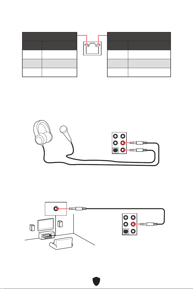
24
LAN Port LED Zustandstabelle
Verbindung/ Aktivität LED
Zustand Bezeichnung
Aus Keine Verbindung
Gelb Verbindung
Blinkt Datenaktivität
Geschwindigkeit LED
Zustand Geschwindigkeit
Off (Aus) 10 Mbit/s
Grün 100/1000 Mbit/s
Orange 2,5 Gbit/s
Audiobuchsen
Audiobuchsen für den Anschluss von einem Kopfhörer und Mikrofon
Audiobuchsen für Stereo-Lautsprecher
AUDIO INPUT

25
Audiobuchsen für 7.1 Kanal Anlage
Audiobuchsen für 4 Kanal Anlage
Audiobuchsen für 5.1 Kanal Anlage
AUDIO INPUT
Rear Front
Center/
Subwoofer
AUDIO INPUT
Rear Front
Center/
Subwoofer
AUDIO INPUT
Rear Front
Side Center/
Subwoofer

26
Antennen installieren
1. Verbinden Sie Antenne mit dem Antennenfuß.
2. Schrauben Sie, wie gezeigt, die Antennen fest an die Wi-Fi Antennenanschlüsse.
11
22
3. Positionieren Sie die Antennen so hoch wie möglich.

27
Übersicht der Komponenten
CPU_FAN1
PUMP_FAN1
SYS_FAN5
SYS_FAN4
JARGB_V2_2
ATX_PWR1
JUSB4
JUSB3
Prozessor
Sockel
CPU_PWR1
CPU_PWR2
DIMMA2
DIMMB1
DIMMB2
DIMMA1
JCI1
JFP1
JBAT1
JOCFS1
LED_SW1
SYS_FAN3
SYS_FAN2
SYS_FAN1
JDASH1
JPWRLED1
JTBT1
JARGB_V2_1
JRGB1
JAUD1
JUSB2
JUSB1
M2_5
M2_1
M2_2
M2_3
M2_4
PCI_E1
PCI_E2
PCI_E3
JFP2
JTPM1

28
Wichtig
Ziehen Sie das Netzkabel ab, bevor Sie die CPU ein- und ausbauen.
Bitte bewahren Sie die CPU Schutzkappe nach der Installation des Prozessors auf.
MSI wird RMA (Return Merchandise Authorization) Anfragen nur dann behandeln,
wenn die Schutzklappe auf dem CPU-Sockel des Motherboards sitzt.
Wenn Sie eine CPU einbauen, denken sie bitte daran, einen CPU-Kühler zu
installieren. Ein CPU-Kühlkörper ist notwendig, um eine Überhitzung zu vermeiden
und die Systemstabilität zu gewährleisten.
Stellen Sie sicher, dass Ihr Kühlkörper eine feste Verbindung mit der CPU
hergestellt hat, bevor Sie Ihr System starten.
Überhitzung beschädigt die CPU und das System nachhaltig. Stellen Sie stets eine
korrekte Funktionsweise des CPU Kühlers sicher, um die CPU vor Überhitzung zu
schützen. Stellen Sie sicher, dass eine gleichmäßige Schicht thermischer Paste
oder thermischen Tapes zwischen der CPU und dem Kühlkörper vorhanden ist, um
die Wärmeableitung zu erhöhen.
Schützen Sie den CPU-Sockel immer mit der Plastikabdeckung, wenn keine CPU
installiert ist.
Verwenden Sie bitte die Installationsanweisung des Kühlkörpers/Kühlers, falls Sie
eine seperate CPU oder einen Kühlkörper/ Kühler erworben haben.
Dieses Motherboard wurde so entworfen, dass es Übertakten unterstützt. Stellen
Sie jedoch bitte sicher, dass die betroffenen Komponenten mit den abweichenden
Einstellungen während des Übertaktens zurecht kommen. Von jedem Versuch
des Betriebes außerhalb der Produktspezifikationen kann nur abgeraten werden.
MSI übernehmt keinerlei Garantie für die Schäden und Risiken, die aus einem
unzulässigem Betrieb oder einem Betrieb außerhalb der Produktspezifikation
resultieren.
CPU Sockel
Erklärung zur LGA1700 CPU
Die Oberseite der LGA 1700 CPU hat vier
Justierungen und ein goldenes Dreieck
um die korrekte Ausrichtung der CPU
auf dem Motherboard zu gewährleisten.
Das goldene Dreieck des Prozessors
definiert die Position des ersten Pins.
Abstand zwischen der Mitte der
CPU und dem nächsten DIMM-
Steckplatz.
50,85 mm
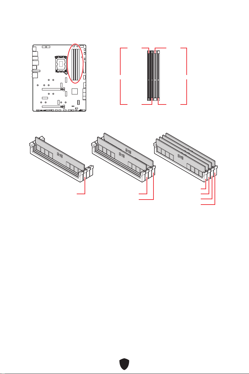
29
DIMM Steckplätze
DIMMA1 DIMMB1
Kanal A Kanal B
DIMMA2 DIMMB2
Speichermodul-Installationsempfehlung
Wichtig
Um einen sicheren Systemstart zu gewährleisten, bestücken Sie immer DIMMA2
zuerst.
Stellen Sie im Dual-Kanal-Modus bitte sicher, dass Sie Module des gleichen
Typs und identischer Speicherdichte in den DIMM Slots unterschiedlicher Kanäle
verwenden.
Einige Speichermodule können beim Übertakten auf einer niedrigeren Frequenz
arbeiten, als der festgelegte Wert - abhängig von dem SPD (Serial Presence Detect).
Stellen Sie im BIOS-Setup mit DRAM Frequency die Speicherfrequenz ein, wenn Sie
mit der festgelegten oder einer höheren Speicherfrequenz arbeiten möchten.
Es wird empfohlen, ein effizienteres Speicherkühlsystem bei einer Vollbestückung
des DIMMs oder beim Übertakten zu verwenden.
Die Stabilität und Kompatibilität beim Übertakten der installierten Speichermodule
sind abhängig von der installierten CPU und den installierten Geräten.
Weitere Informationen zu kompatiblen Speichermodulen finden Sie unter:
www.msi.com.
DIMMA2 DIMMA2
DIMMB2
DIMMA1
DIMMA2
DIMMB1
DIMMB2
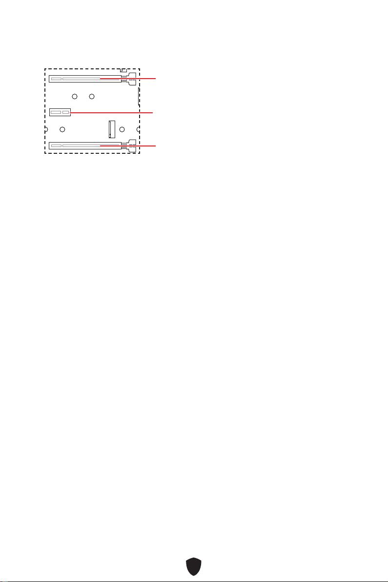
30
PCI_E1~3: PCIe Erweiterungssteckplätze
PCI_E1: PCIe 5.0 x16 (von CPU)
PCI_E2: PCIe 3.0 x1 (vom Z790 Chipsatz)
PCI_E3: PCIe 4.0 x4 (vom Z790 Chipsatz)
Wichtig
Wenn Sie eine große und schwere Grafikkarte einbauen, benötigen Sie einen
Grafikkarten-Stabilisator (Graphics Card Bolster) der das Gewicht trägt und eine
Verformung des Steckplatzes vermeidet.
Für die Installation einer einzelnen PCIe x16 Erweiterungskarte mit optimaler
Leistung, empfehlen wir den PCI_E1 Steckplatz zu verwenden.
Achten Sie darauf, dass Sie den Strom abschalten und das Netzkabel aus der
Steckdose herausziehen, bevor Sie eine Erweiterungskarte installieren oder
entfernen. Lesen Sie bitte auch die Dokumentation der Erweiterungskarte, um
notwendige zusätzliche Hardware oder Software-Änderungen zu überprüfen.
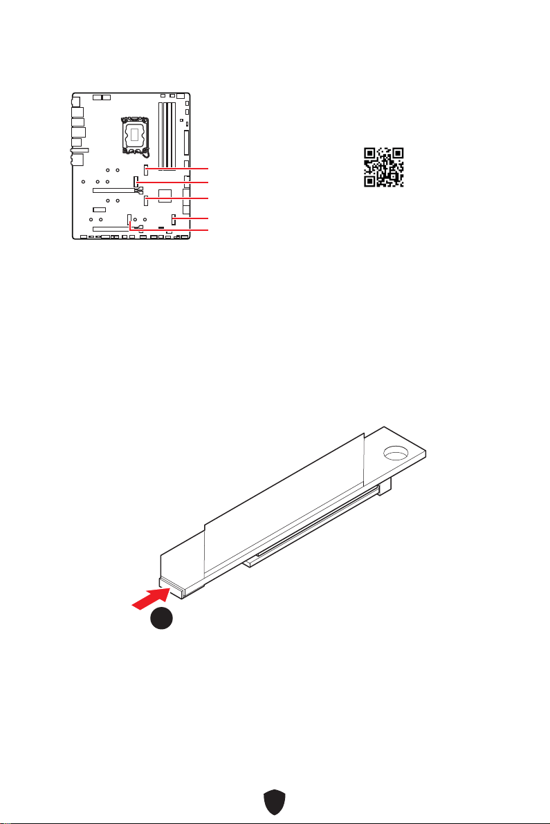
31
M2_1~5: M.2 Steckplätze (Key M)
M2_1
M2_2
M2_4
M2_5
M2_3
Wichtig
Intel® RST unterstützt nur PCIe M.2 SSD mit UEFI ROM.
Wenn Ihre M.2-SSD mit einem eigenen Kühlkörper ausgestattet ist, entfernen
Sie bitte die M.2-Platte und installieren Sie dann die M.2-SSD im M.2-Steckplatz.
Installieren Sie nicht den mit Ihrem Motherboard gelieferten Kühlkörper
Installieren des M.2-Moduls im M2_1-Steckplatz
1. Drücken und halten Sie die Taste am Ende des schraublosen M.2 Shield Frozr-
Kühlkörpers.
11
https://youtu.be/J88vcXeLido
Sehen Sie sich das Video an, um
zu erfahren, wie Sie eine M.2-SSD
mit Stressless M.2 Shield Frozr-
Kühlkörper installieren.
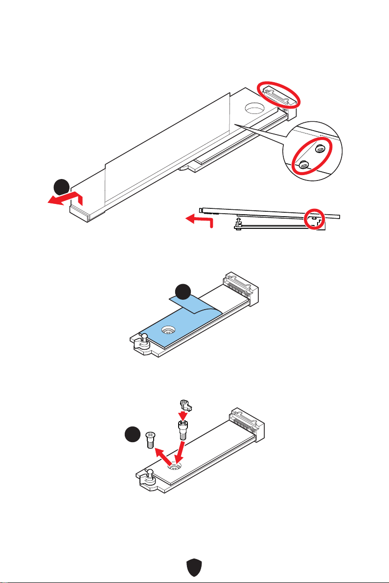
32
2. Heben Sie das Ende des schraublosen M.2 Shield Frozr-Kühlkörpers leicht an und
bewegen Sie ihn nach vorne, um den Kühlkörper zu deinstallieren.
22
3. Entfernen Sie die Schutzfolie von den M.2 Wärmeleitpadsthe des M.2 Kühlkörpers.
33
4. Wenn Sie 2260 SSD installieren, entfernen Sie die Schraube von der M.2-Platte
und installieren Sie dann das mitgelieferte EZ M.2-Clip-Kit auf der M.2-Platte.
Überspringen Sie diesen Schritt, wenn Sie eine 2280 SSD installieren.
44
2260 SSD

33
5. Stecken Sie eine M.2-SSD im 30-Grad-Winkel in den M.2-Steckplatz.
6. Drehen Sie den EZ M.2 Clip, um die M.2 SSD zu befestigen.
30º30º
30º30º
2280 SSD
2260 SSD
66
66
55
55
7. Entfernen Sie die Schutzfolie von den Wärmeleitpads unter dem schraublosen M.2
Shield Frozr-Kühlkörper.
8. Richten Sie die Zapfen unter dem schraublosen M.2 Shield Frozr-Kühlkörper an
den Kerben aus und setzen Sie den Kühlkörper dann wieder ein.
9. Drücken Sie die Endseite des schraubenlosen M.2 Shield Frozr-Kühlkörpers nach
unten, um ihn vollständig zu verriegeln.
99
88
77
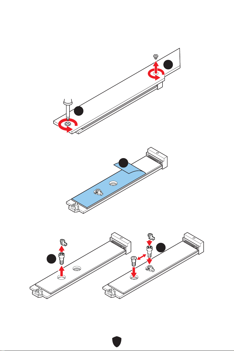
34
Installieren des M.2-Moduls im M2_2-Steckplatz
1. Lösen Sie die Schrauben des M2_1 SHIELD FROZR Kühlkörpers und entfernen Sie
den Kühlkörper.
11
11
2. Entfernen Sie die Schutzfolie von den M.2 Wärmeleitpadsthe des M.2 Kühlkörpers.
22
3. Entfernen oder tauschen Sie die Schrauben entsprechend Ihrer M.2-SSD-Länge
aus. Überspringen Sie diesen Schritt, wenn Sie eine 2280 SSD installieren.
33
33
22110 SSD
2260 SSD

35
4. Stecken Sie eine M.2-SSD im 30-Grad-Winkel in den M.2-Steckplatz.
5. Drehen Sie den EZ M.2 Clip, um die M.2 SSD zu befestigen.
30º30º
30º30º
22110 SSD
2280 SSD
2260 SSD
44
44
55
55
6. Entfernen Sie die Schutzfolie von den Wärmeleitpads unter dem M.2 Shield Frozr-
Kühlkörper.
7. Setzen Sie den M.2 SHIELD FROZR-Kühlkörper wieder ein und sichern Sie ihn.
66
77
77

36
Installieren des M.2-Moduls im M2_3/ M2_4/ M2_5-Steckplatz
1. Lösen Sie die Schraube des M.2-SHIELD FROZR-Kühlkörpers.
11
11
11
11
2. Entfernen Sie die Schutzfolie von den M.2 Wärmeleitpadsthe des M.2 Kühlkörpers.
22
3. Wenn Sie 2260 SSD installieren, entfernen Sie die Schraube von der M.2-Platte
und installieren Sie dann das mitgelieferte EZ M.2-Clip-Kit auf der M.2-Platte.
Überspringen Sie diesen Schritt, wenn Sie eine 2280 SSD installieren.
33
2260 SSD
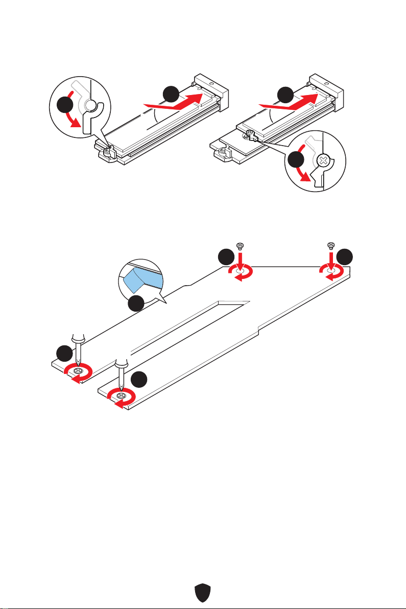
37
4. Stecken Sie eine M.2-SSD im 30-Grad-Winkel in den M.2-Steckplatz.
5. Drehen Sie den EZ M.2 Clip, um die M.2 SSD zu befestigen.
30º30º
30º30º
2280 SSD
2260 SSD
55
44
44
55
6. Entfernen Sie die Schutzfolie vom Wärmeleitpad unter dem M.2 Shield Frozr-
Kühlkörper.
7. Setzen Sie den M.2 SHIELD FROZR-Kühlkörper wieder ein und sichern Sie ihn.
66
77
77 77
77

38
SATA5~8 & SATA_A1~A2: SATA 6Gb/s Anschlüsse
Dieser Anschluss basiert auf der Hochgeschwindigkeitsschnittstelle SATA 6 Gb/s. Pro
Anschluss kann ein SATA Gerät angeschlossen werden.
SATA5
SATA7
SATA_A1
SATA6
SATA8
SATA_A2
Wichtig
Knicken Sie das SATA-Kabel nicht in einem 90° Winkel. Datenverlust könnte die
Folge sein.
SATA-Kabel haben identische Stecker an beiden Enden. Es wird empfohlen den
flachen Stecker auf dem Motherboard einstecken.
JTBT1: Anschluss für Thunderbolt-Erweiterungskarte
Mit diesem Anschluss können Sie eine Ein-/Ausgang der Thunderbolt-
Erweiterungskarte anschließen.
1
2 16
15
Pin Signalname Pin Signalname
1 TBT_FORCE_PWR 2 TBT_S0IX_ENTRY_REQ
3
TBT_CIO_PLUG_
EVENT#
4 TBT_S0IX_ENTRY_ACK
5 SLP_S3#_TBT 6
TBT_PSON_
OVERRIDE_N
7 SLP_S5#_TBT 8 No Pin
9 Ground 10 SMBCLK_VSB
11 DG_PEWAKE# 12 SMBDATA_VSB
13 TBT_RTD3_PWR_EN 14 Ground
15 TBT_CARD_DET_R# 16 PD_IRQ#

39
JAUD1: Audioanschluss des Frontpanels
Dieser Anschluss ermöglicht den Anschluss von Audiobuchsen eines Frontpanels.
1
2 10
9
Pin Signalname Pin Signalname
1 MIC L 2 Ground
3 MIC R 4 NC
5 Head Phone R 6 MIC Detection
7 SENSE_SEND 8 No Pin
9 Head Phone L 10 Head Phone Detection
JFP1, JFP2: Frontpanel-Anschlüsse
Der JFP1-Anschluss steuert das Einschalten, Zurücksetzen und die LEDs an Ihrem
PC-Gehäuse/Gehäuse. Die Power /Reset-Stiftleisten dienen zum Anschluss der
Power-/Reset-Taste. Der Power-LED-Anschluss wird mit der LED-Leuchte am PC-
Gehäuse verbunden, und der HDD-LED-Anschluss zeigt die Aktivität der Festplatte an.
Der JFP2-Anschluss ist für den Signaltongeber und Lautsprecher vorgesehen. Um die
Kabel vom PC-Gehäuse an die richtigen Pins anzuschließen, sehen Sie sich bitte die
folgenden Bilder an.
1
2 10
9
Power LED
Reserved
Power Switch
JFP1
Reset SwitchHDD LED
1
JFP2
Buzzer
Speaker
Wichtig
Bitte beachten Sie, dass Power-LED und HDD-LED eine positive und negative
Verbindung haben, Sie müssen das Kabel mit dem entsprechenden positiven und
negativen Anschluss auf dem Motherboard verbinden. Andernfalls werden die LEDs
nicht richtig funktionieren.

40
Wichtig
Stellen Sie sicher, dass alle Anschlüsse mit den richtigen Anschlüssen des Netzteils
verbunden sind, um einen stabilen Betrieb der Hauptplatine sicherzustellen
CPU_PWR1~2, ATX_PWR1: Stromanschlüsse
Mit diesen Anschlüssen verbinden Sie die ATX Stromstecker.
CPU_PWR1~2
Pin Signalname Pin Signalname
1 Ground 2 Ground
3 Ground 4 Ground
5 +12V 6 +12V
7 +12V 8 +12V
ATX_PWR1
Pin Signalname Pin Signalname
1 +3,3V 2 +3,3V
3 Ground 4 +5V
5 Ground 6 +5V
7 Ground 8 PWR OK
9 5VSB 10 +12V
11 +12V 12 +3,3V
13 +3,3V 14 -12V
15 Ground 16 PS-ON#
17 Ground 18 Ground
19 Ground 20 Res
21 +5V 22 +5V
23 +5V 24 Ground
5
4 1
8
CPU_PWR1~2
24
131
12
ATX_PWR1

41
JCI1: Gehäusekontaktanschluss
Dieser Anschluss wird mit einem Kontaktschalter verbunden
Normal
(Standardwert)
Löse den
Gehäuseeingriff aus
Gehäusekontakt-Detektor verwenden
1. Schließen Sie den JCI1 -Anschluss am Gehäusekontakt-Schalter/ Sensor am
Gehäuse an.
2. Schließen Sie die Gehäuseabdeckung.
3. Gehen Sie zu BIOS > SETTINGS > Security > Chassis Intrusion Configuration.
4. Stellen Sie Chassis Intrusion auf Enabled.
5. Drücken Sie F10 zum Speichern und Beenden und drücken Sie dann die Enter-
Taste, um Ja auszuwählen.
6. Bei eingeschaltetem Computer wird eine Warnmeldung auf dem Bildschirm
angezeigt, wenn die Gehäuseabdeckung wieder geöffnet wird.
Gehäusekontakt-Warnung zurücksetzen
1. Gehen Sie zu BIOS > SETTINGS > Security > Chassis Intrusion Configuration.
2. Stellen Sie Chassis Intrusion auf Reset.
3. Drücken Sie F10 zum Speichern und Beenden und drücken Sie dann die Enter-
Taste, um Ja auszuwählen.
JDASH1: Tuning Controller-Anschluss
An diesem Anschluss wird ein optionales Tuning Controller-Modul angeschlossen.
Pin Signalname Pin Signalname
1 No Pin 2 NC
3
MCU_SMB_SCL_M
4 MCU_SMB_SDA_M
5 VCC5 6 Ground
1
2
5
6
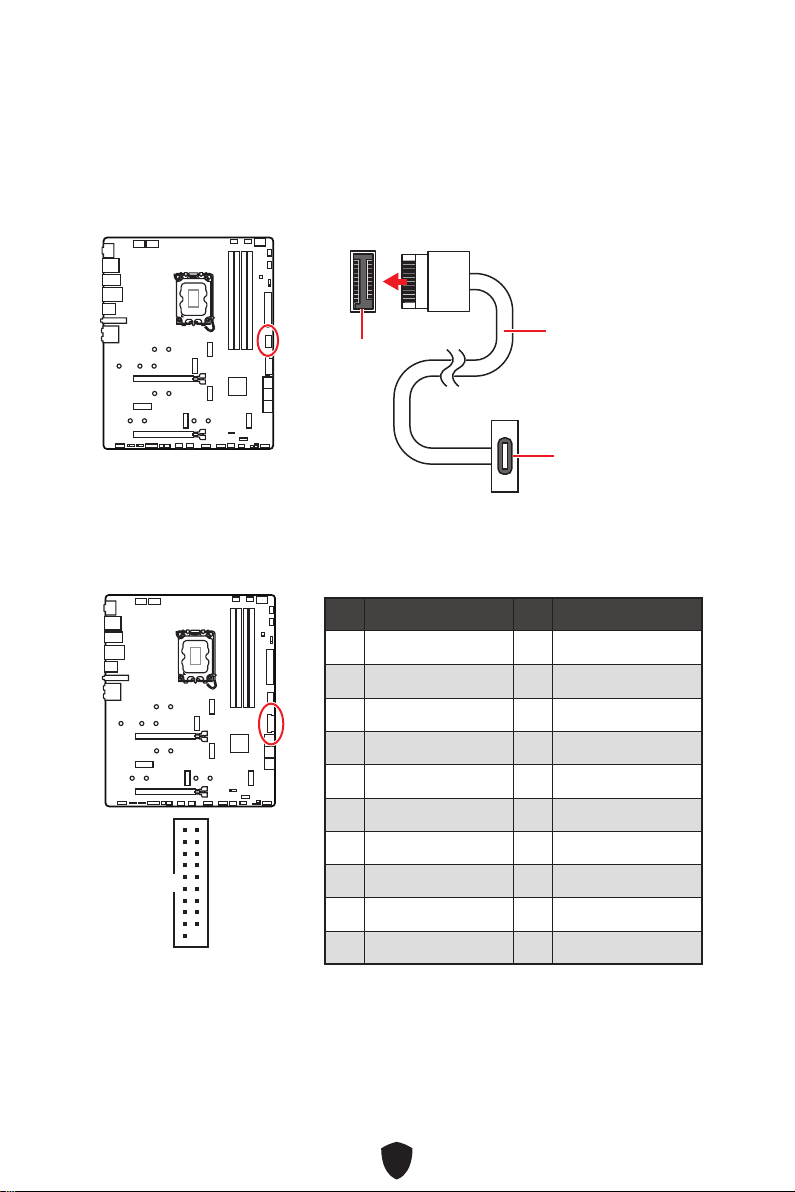
42
JUSB3: USB 3.2 Gen 1 Anschluss
Mit diesem Anschluss können Sie die USB 3.2 Gen 1 5Gbit/s Anschlüsse auf dem
Frontpanel verbinden.
Wichtig
Bitte beachten Sie, dass Sie die mit „Stromführende Leitung“ und „Erdleitung“
bezeichneten Pins korrekt verbinden müssen, ansonsten kann es zu Schäden
kommen
JUSB4: USB 3.2 Gen 2 2x2 Typ-C Anschluss an der
Vorderseite
Mit diesem Anschluss können Sie den USB 3.2 Gen2x2 20Gbps Typ-C Anschluss
auf dem Frontpanel verbinden. Der Anschluss verfügt über ein besonders sicheres
Design. Wenn Sie das Kabel anschließen, müssen Sie es in der entsprechenden
Ausrichtung verbinden.
JUSB4
USB Typ-C Kabel
USB Typ-C
Anschluss auf dem
Frontpanel
Pin Signalname Pin Signalname
1 Power 2 USB3_RX_DN
3 USB3_RX_DP 4 Ground
5 USB3_TX_C_DN 6 USB3_TX_C_DP
7 Ground 8 USB2.0-
9 USB2.0+ 10 Ground
11 USB2.0+ 12 USB2.0-
13 Ground 14 USB3_TX_C_DP
15 USB3_TX_C_DN 16 Ground
17 USB3_RX_DP 18 USB3_RX_DN
19 Power 20 No Pin
1
10 11
20
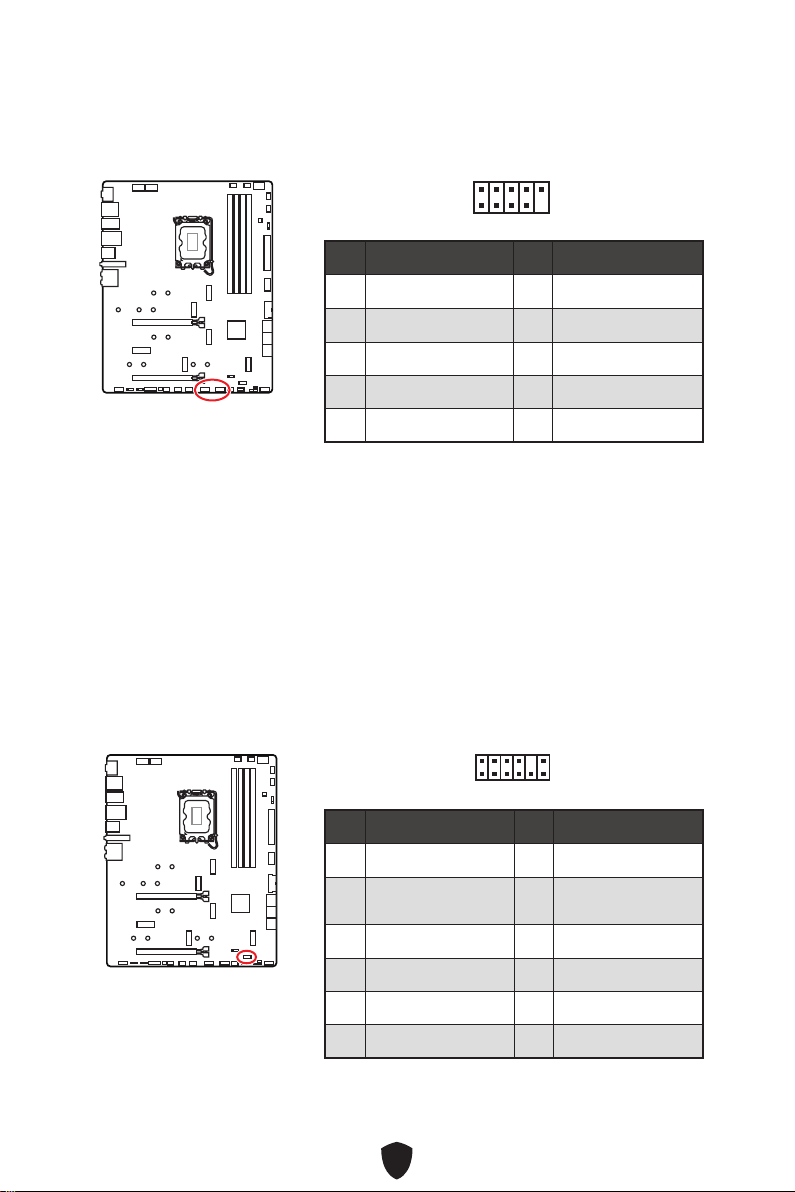
43
JUSB1~2: USB 2.0 Anschlüsse
Mit diesen Anschlüssen können Sie die USB 2.0 Anschlüsse auf dem Frontpanel
verbinden.
Wichtig
Bitte beachten Sie, dass Sie die mit VCC (Stromführende Leitung) und Ground
(Erdung) bezeichneten Pins korrekt verbinden müssen, ansonsten kann es zu
Schäden kommen.
Um ein iPad, iPhone und einen iPod über USB-Anschlüsse aufzuladen, installieren
Sie bitte die MSI® Center-Dienstprogramm.
JTPM1: TPM Anschluss
Dieser Anschluss wird für das TPM Modul (Trusted Platform Module) verwendet.
Weitere Informationen über den Einsatz des optionalen TPM Modules entnehmen Sie
bitte dem TPM Plattform Handbuch.
Pin Signalname Pin Signalname
1 VCC 2 VCC
3 USB0- 4 USB1-
5 USB0+ 6 USB1+
7 Ground 8 Ground
9 No Pin 10 NC
1
2 10
9
Pin Signalname Pin Signalname
1 SPI Power 2 SPI Chip Select
3
Master In Slave Out
(SPI Data)
4
Master Out Slave In
(SPI Data)
5 Reserved 6 SPI Clock
7 Ground 8 SPI Reset
9 Reserved 10 No Pin
11 Reserved 12 Interrupt Request
1
2 12
11
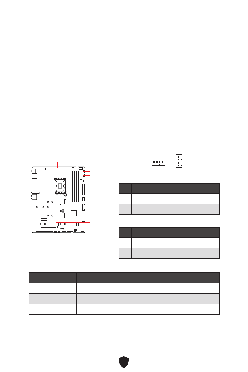
44
CPU_FAN1, PUMP_FAN1, SYS_FAN1~5:
Stromanschlüsse für Lüfter
Diese Anschlüsse können im PWM (Pulse Width Modulation) Modus
oder Spannungsmodus betrieben werden. Im PWM-Modus bieten die
Lüfteranschlüsse konstante 12V Ausgang und regeln die Lüftergeschwindigkeit
per Drehzahlsteuersignal. Im DC-Modus bestimmen die Lüfteranschlüsse
die Lüftergeschwindigkeit durch Ändern der Spannung. Der Auto-Modus der
Lüfteranschlüsse kann den PWM- und DC-Modus automatisch erfassen.
Sie können unter BIOS > HARDWARE MONITOR die Lüfterdrehzahl ändern. Damit
können Sie DC oder PWM auf Ihren Lüftermodus einstellen. Wählen Sie den Smart
Fan Mode, die Lüftergeschwindigkeit ändert sich entsprechend der CPU- oder
Systemtemperatur. Deaktivieren Sie den Smart Fan Mode, der Lüfter dreht sich mit
maximaler Geschwindigkeit.
Wichtig
Überprüfen Sie die ordnungsgemäße Funktion der Lüfter nach dem Umschalten des
PWM-/ DC-Modus.
CPU_FAN1
SYS_FAN2
SYS_FAN1
SYS_FAN3
PUMP_FAN1
SYS_FAN5
SYS_FAN4
1
Pin-Belegung des PWM-Modus
Pin Signalname Pin Signalname
1 Ground 2 +12V
3 Sense 4 Speed Control Signal
Pin-Belegung des DC-Modus
Pin Signalname Pin Signalname
1 Ground 2 Voltage Control
3 Sense 4 NC
Spezifikationen des Lüfteranschlusses
Anschluss Standard-lüftermodus Max. Strom Max. Leistung
CPU_FAN1 Auto Modus 2A 24W
PUMP_FAN1 PWM Modus 3A 36W
SYS_FAN1~5 DC Modus 1A 12W
1
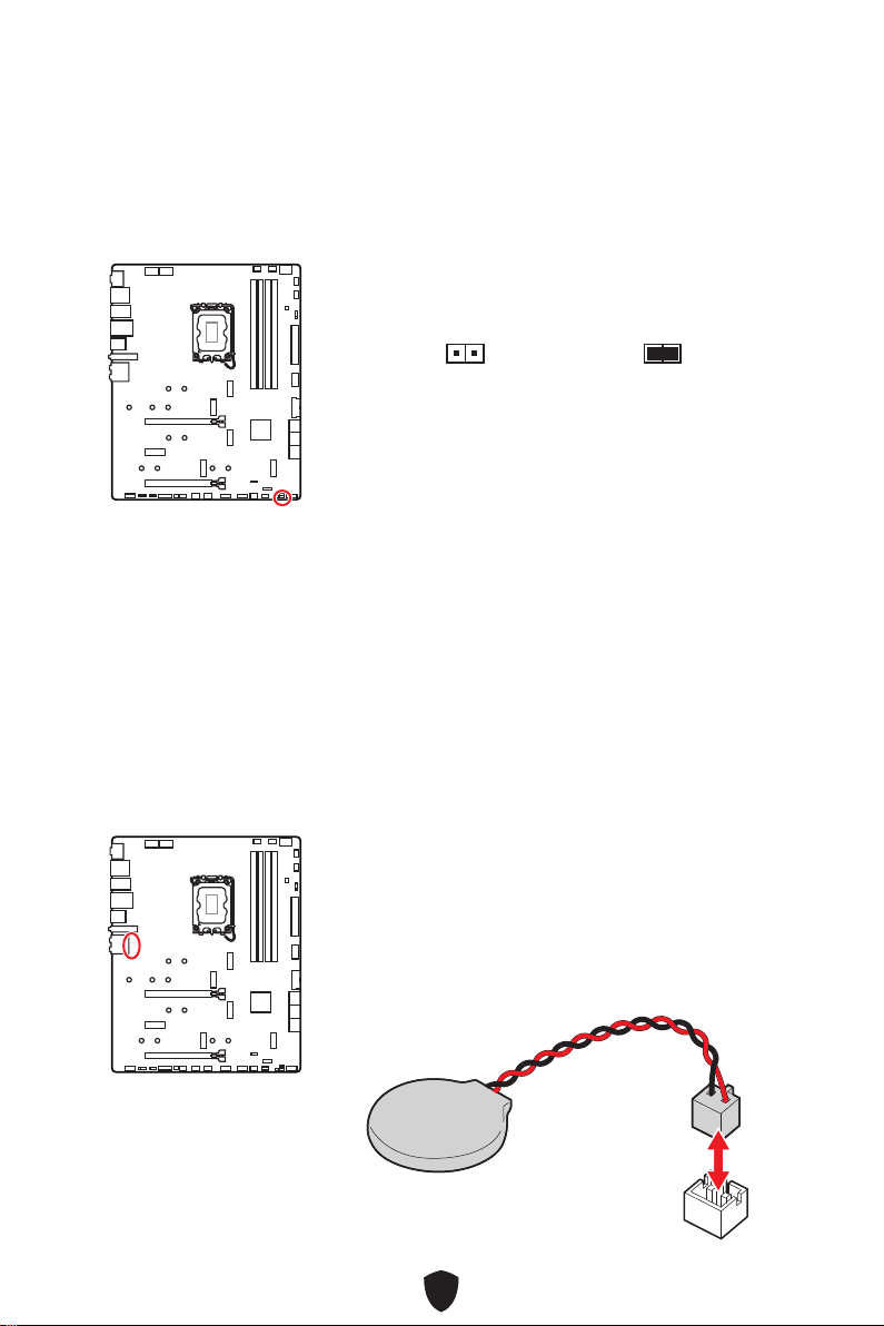
45
JBAT1: Clear CMOS Steckbrücke (Reset BIOS)
Der Onboard CMOS Speicher (RAM) wird durch eine externe Spannungsversorgung
durch eine Batterie auf dem Motherboard versorgt, um die Daten der
Systemkonfiguration zu speichern. Wenn Sie die Systemkonfiguration löschen wollen,
müssen Sie die Steckbrücke für kurze Zeit umsetzen.
Wenn die CMOS-Batterie leer ist, wird die Uhrzeit im BIOS zurückgesetzt und die
Daten der Systemkonfiguration gehen verloren. In diesem Fall müssen Sie die CMOS-
Batterie ersetzen.
Daten
beibehalten
(Standardwert)
CMOS-Daten
löschen/ Reset des
BIOS
Rücksetzen des BIOS auf Standardwerte
1. Schalten Sie den Computer ab und ziehen Sie das Netzkabel ab.
2. Verwenden Sie eine Steckbrücke, um JBAT1 für 5-10 Sekunden kurzzuschließen.
3. Entfernen Sie die Steckbrücke von JBAT1.
4. Stecken Sie das Kabel Ihres Computers in die Steckdose hinein und schalten Sie
den Computer ein.
Ersetzen der Batterie
1. Trennen Sie das Batteriekabel vom BAT1-Anschluss
und entfernen Sie die Batterie.
2. Schließen Sie die neue CR2032-Batterie mit Kabel an
den BAT1-Anschluss an.

46
Wichtig
Der JRGB Anschluss unterstützt bis zu 2 Metern 5050 RGB LED-Streifen (12V/G/
R/B) mit der maximalen Leistung von 3 A (12 V)
Schalten Sie die Stromversorgung aus und ziehen Sie das Netzkabel ab, bevor Sie
die RGB-LED-Streifen ein- und ausbauen.
Bitte verwenden Sie die MSI-Software zur Steuerung des LED-Leuchtstreifens.
JRGB1: RGB LED Anschluss
Mit dem JRGB Anschluss können Sie den 5050 RGB-LED-Streifen (12 V) anschließen.
1
G
R
B
JRGB Anschluss
JRGB Verlängerungskabel
5050 RGB LED Streifen 12V
RGB-LED-Streifen anschließen
1
1
G
R
B
JRGB Anschluss
System-Lüfter -Anschluss
RGB-LED-Lüfteranschluss
RGB LED Lüfter
Pin Signalname Pin Signalname
1 +12V 2 G
3 R 4 B
1
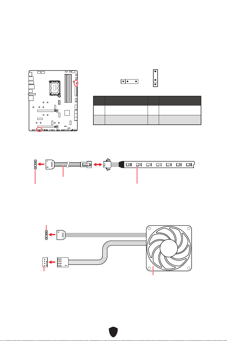
47
JARGB_V2_1~2: A-RAINBOW V2 (ARGB Gen2) LED
Anschlüsee
Mit den JARGB_V2-Anschlüssen können Sie die ARGB Gen2 und die ARGB-basierten
LED-Streifen anschließen. Der JARGB_V2-Anschluss unterstützt bis zu 240 einzeln
adressierbare RGB-LEDs mit einer maximalen Nennleistung von 3 A (5 V).
Pin Signalname Pin Signalname
1 +5V 2 Data
3 No Pin 4 Ground
1
1
1
1
1
D
+5V
JARGB_V2 Anschluss
JARGB_V2 Anschluss
System-Lüfter -Anschluss
JRAINBOW Verlängerungskabel
ARGB/ ARGB Gen2 LED-Streifen
Adressierbarer RGB-LED-Streifen anschließen
Adressierbarer RGB-LED-Lüfteranschluss
ARGB/ ARGB Gen2 LED-Lüfter
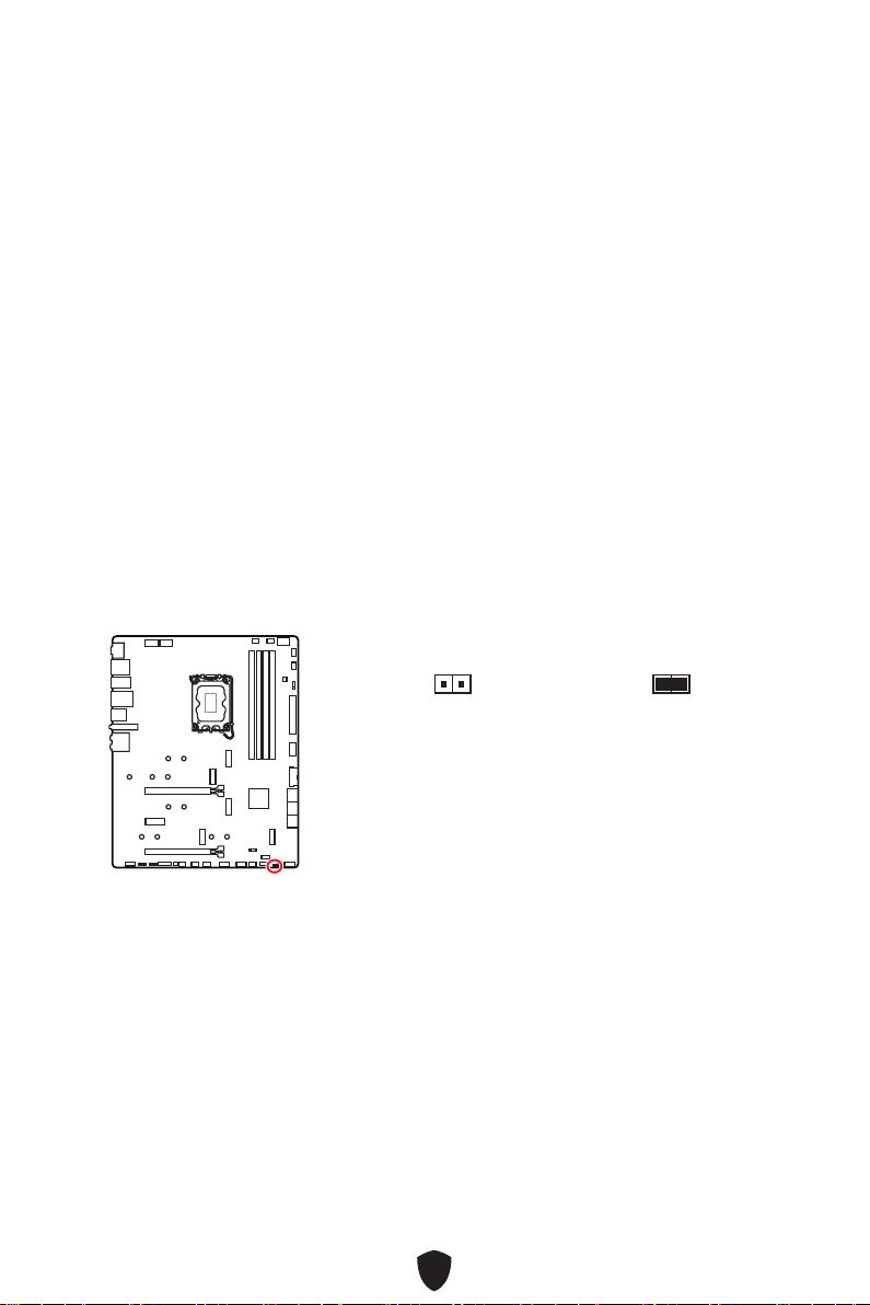
48
ACHTUNG
Schließen Sie nur passende LED-Streifen an. Der JRGB-Anschluss und der JARGB_
V2-Anschluss liefern unterschiedliche Spannungen, und das Anschließen des ARGB
5V LED-Streifens an den JRGB-Anschluss führt zu einer Beschädigung des LED-
Streifens.
Wichtig
Wenn Sie die ARGB Gen1- und ARGB Gen2-LED-Streifen an denselben Anschluss
anschließen, kann dies unter Umständen Probleme verursachen. Bitte verwenden
Sie ARGB Gen1 LED und ARGB Gen2 LED-Streifen nicht miteinander.
Es wird empfohlen, LED-Streifen mit der gleichen Spezifikation zu installieren, um
die besten Effekte zu erzielen.
Schalten Sie die Stromversorgung aus und ziehen Sie das Netzkabel ab, bevor Sie
die RGB-LED-Streifen ein- und ausbauen.
Bitte verwenden Sie die MSI-Software zur Steuerung des LED-Leuchtstreifens.
Normal
(Standardwert)
Booten Sie mit den
gespeicherten BIOS-
Einstellungen.
Aktiviert
Wenden Sie die BIOS-
Standardeinstellungen
und den niedrigeren
PCIe-Modus (von der
CPU) für den sicheren
Start an.
JOCFS1: Steckbrücke für sicheren Start
Diese Steckbrücke wird für den sicheren Start verwendet. Nach der Aktivierung
startet das System mit den Standardeinstellungen und dem niedrigeren PCIe-Modus
(von der CPU).
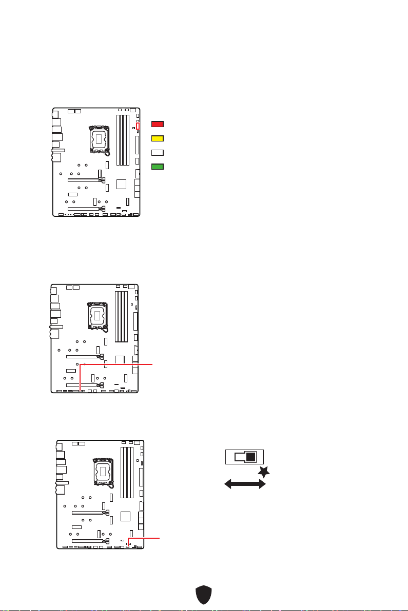
49
EZ DEBUG LED
Diese LEDs zeigen den Debug-Status des Motherboards an.
CPU - CPU wird nicht erkannt oder ist fehlerhaft.
DRAM - DRAM wird nicht erkannt oder ist fehlerhaft.
VGA - GPU wird nicht erkannt oder ist fehlerhaft
BOOT - Boot-Gerät wird nicht erkannt oder ist fehlerhaft.
Onboard LEDs
JPWRLED1 - LED Stromzufuhr
LED_SW1: EZ LED Steuerung
Mit diesem Schalter werden alle LEDs des Motherboards ein- und ausgeschaltet.
LED_SW1
LED_OFF
LED_EIN
(Standardwert)
JPWRLED1: LED Stromzufuhr
Dieser Anshcluss ermöglicht es dem Fachhändler die integrierten LED-Lichteffekte
zu zeigen.
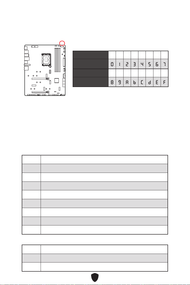
50
Debug-Code-LED
Die Debug-Code-LED-Anzeige zeigt den Fortschritt und das Fehlercode während und
nach dem POST-Vorgang an. Einzelheiten entnehmen Sie bitte der Debug-Code LED-
Tabelle.
Boot-Phasen
Sicherheit (SEC) – Low-Level-Initialisierung beim Start
Pre-EFI-Initialisierung (PEI) – Speicher-Initialisierung
Ausführungsumgebung des Treibers (DXE) – Primäre Hardware-Initialisierung
Auswahl des Boot-Gerätes (BDS) – Systemeinstellungen, Pre-OS Benutzer-Interface
& Auswahl eines Boot-Gerätes (CD/DVD, HDD, USB, Netzwerk, Gehäuse, …)
Debug-Code-LED-Tabelle
SEC-Fortschritt-Codes
01 Computerstart. Reset Typ-Erkennung (Soft/Hard-Reset)
02 AP-Initialisierung vor dem Mikrocode-Ladevorgang
03 AP-Initialisierung vor dem Mikrocode-Ladevorgang
04 PCH-Initialisierung vor dem Mikrocode- Ladevorgang
06 Mikrocode-Ladevorgang
07 Nach der Mikrocode-Ladung initialisiert die AP
08 AP-Initialisierung nach dem Mikrocode- Ladevorgang
09 PCH-Initialisierung nach dem Mikrocode- Ladevorgang
0B Cache-Initialisierung
SEC-Fehler-Codes
0C - 0D Reserviert für zukünftige AMI SEC Fehler-Codes
0E Der Microcode wurde nicht gefunden
0F Der Microcode wurde nicht geladen
Hexadezimalzeichen
Hexadecimal 0 1 2 3 4 5 6 7
LED-Anzeige
Hexadecimal 8 9 A B C D E F
LED-Anzeige
51
PEI-Fortschritt-Codes
10 PEI-Kern wird gestartet
11 Pre-Memory CPU-Initialisierung wird gestartet
12 - 14 Pre-Memory CPU-Initialisierung (CPU-spezifisch)
15 Pre-Memory System-Agent-Initialisierung wird gestartet
16 - 18 Pre-Memory System-Agent-Initialisierung (System-Agent spezifisch)
19 Pre-Memory PCH-Initialisierung wird gestartet
1A - 1C Pre-Memory PCH- Initialisierung (PCH-Modul spezifisch)
2B Speicher-Initialisierung. Speicher-Initialisierung. Programmierung des
Speicher-Timings
2C Speicher-Initialisierung. Speicher -Erfassung
2D Speicher-Initialisierung. Programmierung des Speicher-Timings
2E Speicher-Initialisierung. Konfiguration des Speichers
2F Speicher-Initialisierung (sonstige)
31 Speicher ist installiert
32 CPU Post-Memory-Initialisierung wird gestartet
33 CPU Post-Memory-Initialisierung. Cache-Initialisierung
34 CPU Post-Memory-Initialisierung. Application Processor (AP)
Initialisierung
35 CPU Post-Memory-Initialisierung. Boot Strap Prozessorauswahl (BSP)
36 CPU Post-Memory-Initialisierung. System Management Mode (SMM)
Initialisierung
37 Post-Memory System-Agent-Initialisierung wird gestartet
38 - 3A Post-Speicher-System-Agent Initialisierung (System Agent spezifisch)
3B Pre-Memory PCH-Initialisierung wird gestartet
3C - 3E Post-Memory PCH-Initialisierung wird gestartet
4F DXE IPL wird gestartet
52
PEI-Fehler-Codes
50 Die Speicher-Initialisierung ist fehlgeschlagen. Ungültiger Speichertyp
oder nicht kompatible Speichergeschwindigkeit
51 Die Speicher-Initialisierung ist fehlgeschlagen. Die SPD-Lesung ist
fehlgeschlagen
52 Die Speicher-Initialisierung ist fehlgeschlagen. Ungültige Speichergröße
oder nicht abgestimmte Speichermodule
53 Die Speicher-Initialisierung ist fehlgeschlagen. Kein nutzbarer Speicher
erkannt
54 Unspezifizierte Speicher-Initialisierungsfehler.
55 Speicher ist nicht installiert
56 Ungültiger CPU-Typ oder Geschwindigkeit
57 Inkompatibilität der CPU
58 Der CPU-Selbsttest ist fehlgeschlagen oder es liegt ein CPU-Cache-
Fehler vor
59 CPU Micro-Code wurde nicht gefunden oder das Updaten des Micro-
Codes ist fehlgeschlagen
5A Fehler in interner CPU
5B Reset-PPI ist nicht verfügbar
5C - 5F Reserviert für zukünftige AMI-Fehlercodes
DXE-Fortschritt-Codes
60 DXE Core wird gestartet
61 NVRAM-Initialisierung
62 Installation des PCH Runtime Services
63 CPU DXE-Initialisierung wird gestartet
64 - 67 CPU DXE-Initialisierung (CPU modulspezifisch)
68 PCI Host Bridge Initialisierung
69 System Agent DXE Initialisierung wird gestartet
6A System Agent DXE SMM Initialisierung wird gestartet
6B - 6F System Agent DXE Initialisierung (modulspezifischer System Agent)
53
70 PCH DXE Initialisierung wird gestartet
71 PCH DXE SMM Initialisierung wird gestartet
72 PCH-Geräte Initialisierung
73 - 77 PCH DXE Initialisierung (PCH modulspezifisch)
78 ACPI Modul Initialisierung
79 CSM Initialisierung
7A - 7F Reserviert für zukünftige AMI-DXE-Codes
90 Boot Device Selection (BDS) Phase wird gestartet
91 Treiber-Verbindung wird gestartet
92 PCI Bus Initialisierung wird gestartet
93 PCI Bus Hot Plug Controller Initialisierung
94 PCI Bus Enumeration 32
95 PCI Bus Request Resources
96 PCI Bus Assign Resources
97 Verbindung der Konsolen-Ausgangsgeräte
98 Verbindung der Konsolen-Eingangsgeräte
99 Super-IO-Initialisierung
9A USB-Initialisierung wird gestartet
9B USB-Rücksetzung
9C USB-Erkennung
9D USB-Aktivierung
9E/ 9F Reserviert für zukünftige AMI-Codes
A0 IDE Initialisierung wird gestartet
A1 IDE-Rücksetzung
A2 IDE-Erkennung
A3 IDE-Aktivierung
A4 SCSI Initialisierung wird gestartet
54
A5 SCSI-Rücksetzung
A6 SCSI-Erkennung
A7 SCSI-Aktivierung
A8 Bereite Kennwortüberprüfung vor
A9 Beginn der Einstellung
AB Warten auf Eingabe
AD Bereit für Boot-Event
AE Legacy Boot Event
AF Beendet das Boot-Services-Event
B0 Laufzeit stellt virtuelle MAP Start-Adresse ein
B1 Laufzeit stellt virtuelle MAP End-Adresse ein
B2 Legacy Option ROM Initialisierung
B3 System-Rücksetzung
B4 USB Hot-Plug
B5 PCI-Bus Hot-Plug
B6 NVRAM aufräumen
B7 Setzt die Konfiguration zurück (setzt die NVRAM-Einstellungen zurück)
B8 - BF Reserviert für zukünftige AMI-Codes
DXE-Fehler-Codes
D0 CPU-Initialisierungs-Fehler
D1 System-Agent-Initialisierungs-Fehler
D2 PCH-Initialisierungs-Fehler
D3 Einige der Architektur-Protokolle sind nicht verfügbar
D4 PCI-Ressourcenzuordnungsfehler. Keine ausreichenden Ressourcen
verfügbar.
D5 Kein Platz für Legacy-Option-ROM
D6 Kein Konsolen-Ausgangsgerät gefunden
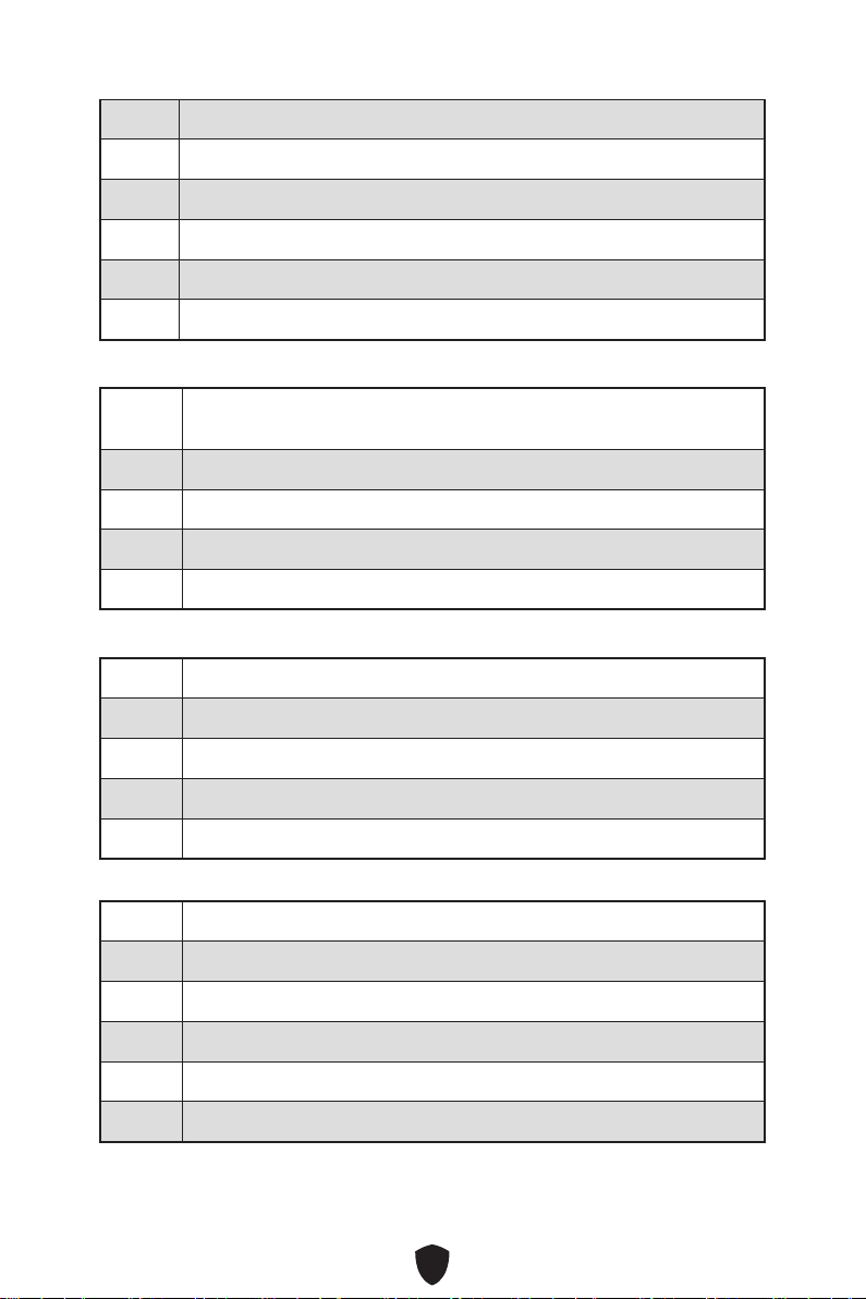
55
D7 Kein Konsolen-Eingangsgeräte gefunden
D8 Ungültiges Passwort
D9 Fehler beim Laden der Boot-Option (Load-Image gibt Fehler zurück)
DA Boot Option ist fehlgeschlagen (Start-Image gibt Fehler zurück)
DB Flash-Update ist fehlgeschlagen
DC Das Reset-Protokoll steht nicht zur Verfügung
S3-Wiederaufnahme-Fortschritt-Codes
E0 S3-Wiederaufnehmen wird gestartet (S3-Wiederaufnehmen-PPI wird von
DXE IPL aufgerufen)
E1 Führt das S3-Boot-Skript aus
E2 Veröffentlicht Video neu
E3 OS S3 Ruhezustand
E4 - E7 Reserviert für zukünftige AMI-Fortschrittscodes
S3 Wiederaufnahme Fehler-Codes
E8 Das S3-Wiederaufnehmen ist fehlgeschlagen
E9 Das S3-Wiederaufnehmen PPI wurde nicht gefunden
EA Boot-Skript-Fehler bei der S3-Wiederaufnehmen
EB S3 OS Ruhezustand-Fehler
EC - EF Reserviert für zukünftige AMI-Fehlercodes
Wiederherstellung Fortschritt-Codes
F0 Wiederherstellung ausgelöst durch die Firmware (Auto recovery)
F1 Wiederherstellung ausgelöst durch den Benutzer (Forced recovery)
F2 Der Wiederherstellungsprozess wurde gestartet
F3 Das Image der Wiederherstellung-Firmware wurde gefunden
F4 Das Image der Wiederherstellung-Firmware wurde geladen
F5 - F7 Reserviert für zukünftige AMI-Fortschrittscodes
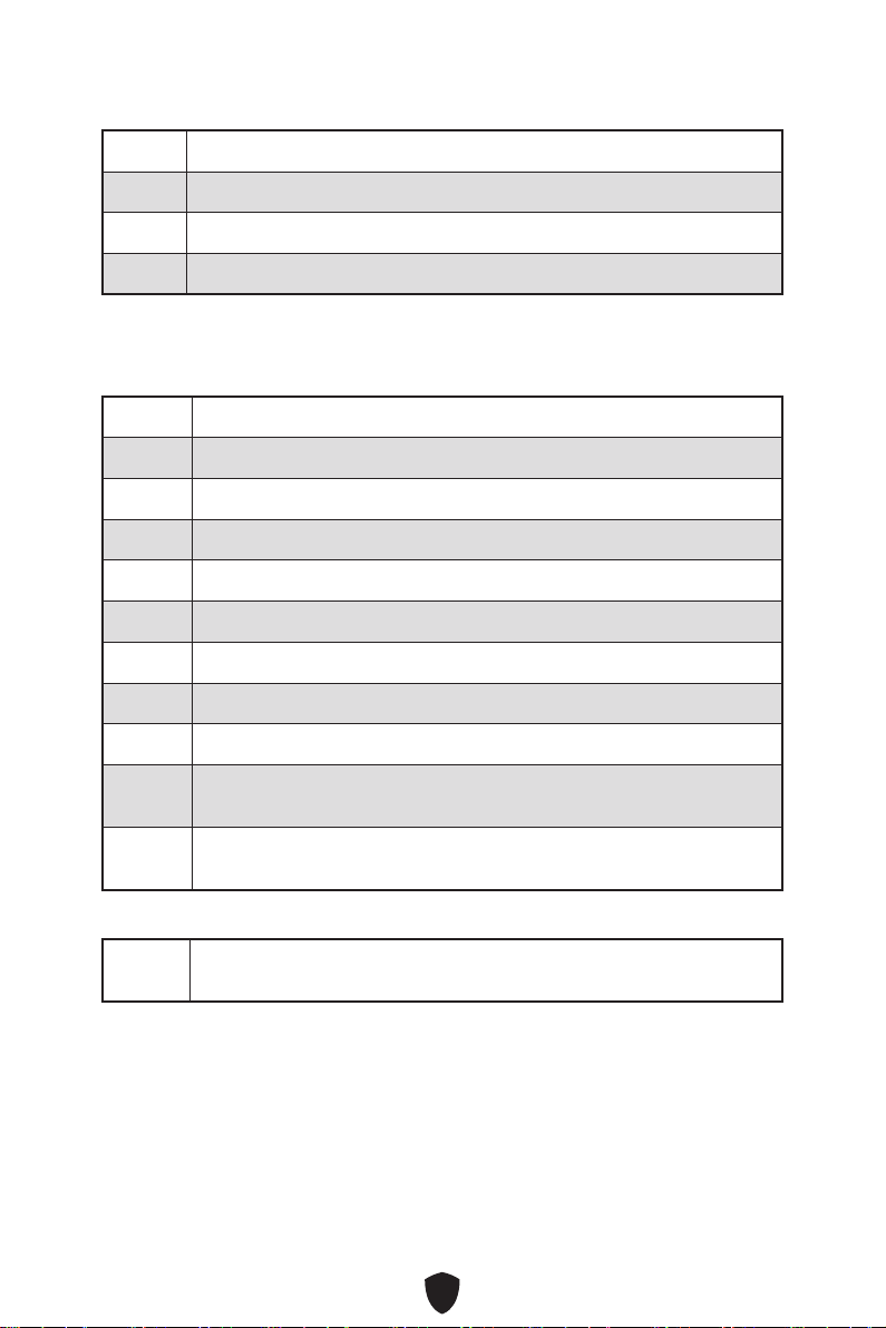
56
Wiederherstellung Fehler-Codes
F8 Wiederherstellung-PPI ist nicht verfügbar
F9 Wiederherstellung-Kapsel ist nicht gefunden
FA Ungültige Wiederherstellung-Kapsel
FB - FF Reserviert für zukünftige AMI-Fehlercodes
ACPI Status-Codes
Nach dem Start erscheinen die folgende Codes und versetzen das Betriebssystem in
den ACPI-Modus.
01 Das System geht in den Ruhezustand S1
02 Das System geht in den Ruhezustand S2
03 Das System geht in den Ruhezustand S3
04 Das System geht in den Ruhezustand S4
05 Das System geht in den Ruhezustand S5
10 Das System beendet den Ruhezustand S1
20 Das System beendet den Ruhezustand S2
30 Das System beendet den Ruhezustand S3
40 Das System beendet den Ruhezustand S4
AC Das System hat auf den ACPI-Modus umgestellt. Interrupt-Controller
ist im PIC-Modus
AA Das System hat auf den ACPI-Modus umgestellt. Interrupt-Controller
ist im APIC-Modus
CPU-Temperatur
00 - 99 Zeigt die aktuelle CPU-Temperatur an, sobald das System das
Betriebssystem vollständig geladen hat.

57
Installation von OS, Treibern & MSI Center
Laden Sie die neuesten Treiber und Dienstprogramme von www.msi.com herunter
und aktualisieren Sie sie.
Installation von Windows 10/ Windows 11
1. Schalten Sie den Computer ein.
2. Legen Sie die Windows 10/ Windows 11-Installations-Disk oder das USB-
Flashlaufwerk in das optisches Laufwerk.
3. Drücken Sie die Taste Restart auf dem Computergehäuse.
4. Drücken Sie die F11-Taste während des POST-Vorgangs (Power-On Self Test), um
das Bootmenu zu öffnen.
5. Wählen Sie die Windows 10/ Windows 11-Installations-Disk oder USB aus dem
Bootmenu.
6. Wenn eine entsprechende Meldung Press any key to boot from CD or DVD...
angezeigt wird, drücken Sie eine beliebige Taste Wenn diese Nachricht nicht
angezeigt wird, überspringen Sie bitte diesen Schritt.
7. Folgen Sie den Anweisungen auf dem Bildschirm, um das Dienstprogramm
„Windows 10/ Windows 11“ zu installieren.
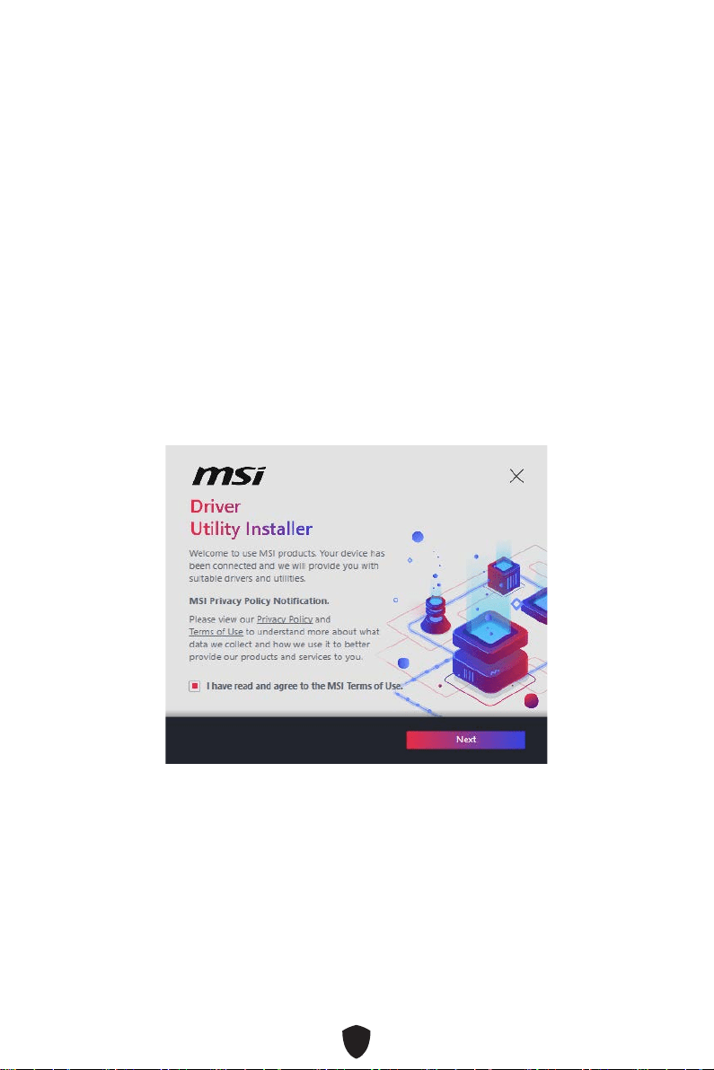
58
Installation von Treibern mit dem MSI Driver Utility
Installer
Wichtig
Einige neue Netzwerkchips wurden von Windows 10/Windows 11 nicht nativ
unterstützt. Es wird empfohlen, den LAN-Treiber zu installieren, bevor Sie die Treiber
mit dem MSI Driver Utility Installer installieren. Informationen zur Installation des
LAN-Treibers für Ihr Motherboard finden Sie unter: www.msi.com.
Das MSI DUI wird nur einmal angezeigt. Wenn Sie es während des Vorgangs
abbrechen oder schließen, lesen Sie bitte das Kapitel „Live Update“ im MSI Center-
Handbuch, um die Treiber zu installieren. Sie können auch zu www.msi.com gehen,
um Ihr Motherboard zu durchsuchen und die Treiber herunterzuladen.
Der MSI DUI (Driver Utility Installer) muss über das Internet installiert werden.
1. Starten Sie Ihren Computer mit Windows 10/ Windows 11.
2. Wählen Sie Start > Einstellungen > Windows-Update , und wählen Sie dann im
Menü „Nach Updates suchen“.
3. MSI Driver Utility Installer wird automatisch angezeigt.
4. Aktivieren Sie das Kontrollkästchen „Ich habe die MSI-Nutzungsbedingungen
gelesen und stimme ihnen zu“ und klicken Sie dann auf „Weiter“.

59
5. Aktivieren Sie das Kontrollkästchen „Alle auswählen“ in der unteren linken Ecke
und klicken Sie auf „Installieren“, um MSI Center und Treiber zu installieren. Der
Fortschritt der Installation wird am unteren Rand des Fensters angezeigt.
6. Nachdem die Installation erfolgreich ausgeführt wurde, klicken Sie auf
Fertigstellen.
60
Installieren von Treibern mit MSI USB-Laufwerk
1. Starten Sie Ihren Computer mit Windows 10/ Windows 11.
2. Legen Sie das MSI USB-Laufwerk am USB-Anschluss.
3. Sie können eine Disc-Image-Datei sehen, die Treiber und Dienstprogramme auf
dem USB-Laufwerk enthält. Doppelklicken Sie auf die Datei, um sie zu öffnen.
4. Führen Sie eine Anwendungsdatei namens DVDSetup aus.
5. Der Installer wird eine Liste aller benötigten Treiber auf der Treiber/ Software-
Registerkarte finden.
6. Klicken Sie auf Install in der rechten unteren Ecke des Fensters.
7. Die Treiber-Installation läuft. Wenn die Installation abgeschlossen ist, werden Sie
dazu aufgefordet, den Computer neu zu starten.
8. Klicken Sie zum Beenden auf OK.
9. Starten Sie Ihren Computer neu.
MSI Center
MSI Center ist eine Anwendung, mit der Sie die Spieleinstellungen einfach optimieren
und die Software zur Erstellung von Inhalten einstellen können. Außerdem können Sie
LED-Lichteffekte in PCs und anderen MSI-Produkten steuern und synchronisieren.
Mit MSI Center können Sie ideale Modi einstellen, die Systemleistung überwachen und
die Lüftergeschwindigkeit anpassen.
MSI Center Benutzerhandbuch
Wenn Sie weitere Informationen zu MSI Center wünschen, besuchen Sie
bitte
http://download.msi.com/manual/mb/MSICENTER.pdf
oder scannen Sie den QR-Code.
Wichtig
Die Funktionen können je nach Produkt variieren.

61
UEFI BIOS
Das MSI UEFI-BIOS ist mit der UEFI-Architektur (Unified Extensible Firmware
Interface) kompatibel. Das UEFI-BIOS hat viele neue Funktionen und besitzt Vorteile,
die das traditionelle BIOS nicht bieten kann. Es wird zukünftige PCs und Geräte, die
der UEFI-Firmware-Architektur entsprechen, vollständig unterstützen. Das MSI
UEFI-BIOS verwendet UEFI als Standard-Startmodus, um die Funktionen des neuen
Chipsatzes voll auszunutzen.
Wichtig
Der Begriff „BIOS“ bezieht sich in diesem Benutzerhandbuch auf das UEFI-BIOS,
sofern nicht anders angegeben.
Vorteile von UEFI
Schnelles Booten - UEFI kann das Betriebssystem direkt booten und den BIOS-
Selbsttestprozess speichern. Außerdem entfällt die Zeit, um während des POST in
den CSM-Modus zu wechseln.
Unterstützt Festplattenpartitionen, die größer als 2 TB sind.
Unterstützt mehr als 4 primäre Partitionen mit einer GUID-Partitionstabelle (GPT).
Unterstützt eine unbegrenzte Anzahl an Partitionen.
Unterstützt den vollen Funktionsumfang neuer Geräte – neue Geräte bieten
möglicherweise keine Abwärtskompatibilität.
Unterstützt sicheren Start – UEFI kann die Gültigkeit des Betriebssystems
überprüfen, um sicherzustellen, dass keine Malware den Startvorgang
beeinträchtigt.
Inkompatible UEFI-Fälle
32-Bit-Windows-Betriebssystem - Dieses Motherboard unterstützt nur das 64-Bit-
Windows 10/ Windows 11-Betriebssystem.
Ältere Grafikkarten - Das System erkennt Ihre Grafikkarte. Bei Erkennung einer
nicht kompatiblen Grafikkarte wird die Warnmeldung „Auf dieser Grafikkarte
wurde keine GOP-Unterstützung (Graphics Output Protocol) erkannt“ angezeigt.
Wichtig
Wir empfehlen Ihnen, eine GOP / UEFI-kompatible Grafikkarte zu nutzen oder eine
CPU mit integrierter Grafikeinheit zu verwenden, um eine normale Funktion des
Systems zu gewährleisten.
Wie überprüfe ich den BIOS-Modus?
1. Schalten Sie den Computer ein.
2. Während des BOOT-Vorgangs drücken Sie die Taste ENTF, wenn die Meldung
Press DEL key to enter Setup Menu, F11 to enter Boot Menu erscheint.
3. Nach dem Aufrufen des BIOS können Sie den BIOS-Modus oben auf dem
Bildschirm überprüfen.
BIOS Mode: UEFI

62
BIOS Setup
Die Standardeinstellungen bieten die optimale Leistung für die Systemstabilität unter
Normalbedingungen. Sie sollten immer die Standardeinstellungen behalten, um
mögliche Schäden des Systems oder Boot-Fehler zu vermeiden, außer Sie besitzen
ausreichende BIOS Kenntnisse.
Wichtig
BIOS Funktionen werden für eine bessere Systemleistung kontinuierlich
aktualisiert. Deswegen können die Beschreibungen leicht von der letzten Fassung
des BIOS abweichen und sollten demnach nur als Anhaltspunkte dienen. Für eine
Beschreibung der BIOS Funktionen rufen Sie die HELP Informationstafel aus.
Die BIOS-Bildschirme, -Optionen und -Einstellungen variieren je nach System.
Öffnen des BIOS Setups
Während des BOOT-Vorgangs drücken Sie die Taste ENTF, wenn die Meldung Press
DEL key to enter Setup Menu, F11 to enter Boot Menu erscheint.
Funktionstasten
F1: Allgemeine Hilfe
F2: Hinzufügen/Entfernen eines Favoritenpunkts
F3: Öffnen des Favoriten Menüs
F4: Öffnen des Menüs CPU-Spezifikationen
F5: Öffnen des Memory-Z Menüs
F6: Laden der ursprünglichen Setup-Standardwerte
F7: Wechselt zwischen dem Erweiterten-Modus und EZ-Modus
F8: OC-Profil wird vom USB-Stick geladen
F9: OC-Profil wird auf einem USB-Stick gespeichert
F10: Speichern oder Zurücksetzen der Änderungen*
F12: Macht einen Screenshot und speichert auf einen FAT/FAT32-USB-Laufwerk.
Strg+F: Öffnet die Suchseite
* Beim Drücken der F10 Taste wird das Fenster zum Speichern der Einstellungen
angezeigt. Wählen Sie Yes, um die Wahl zu bestätigen, oder No, um die derzeitige
Einstellung beizubehalten.
BIOS-Benutzerhandbuch
Wenn Sie weitere Anweisungen zur BIOS-Einrichtung wünschen, lesen Sie
bitte
https://download.msi.com/archive/mnu_exe/mb/Intel700BIOS.pdf
oder scannen Sie den QR-Code.
Wichtig
Die Funktionen können je nach Produkt variieren.
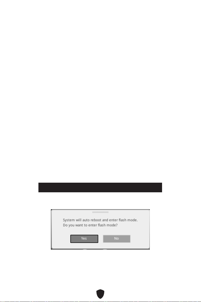
63
Reset des BIOS
Sie können die Werkseinstellung wieder herstellen, um bestimmte Probleme zu
lösen. Es gibt verschiedene Möglichkeiten, um das BIOS zurückzusetzen:
Öffnen Sie das BIOS und drücken Sie F6, um optimierten Einstellungen zu laden.
Schließen Sie die Clear CMOS Steckbrücke an das Motherboard an.
Drücken Sie die Clear CMOS Taste auf der Rückseite E/A des Panels.
Wichtig
Stellen Sie sicher, dass Ihr Computer ausgeschaltet ist, bevor Sie die CMOS-Daten
löschen. Bitte lesen Sie für Informationen zum BIOS-Reset im Bereich „Clear CMOS
Steckbrücke/ Taste“ nach.
Aktualisierung des BIOS
Aktualisierung des BIOS mit dem M-FLASH-Programm
Vorbereitung:
Laden Sie bitte die neueste BIOS Version, die dem Motherboard-Modell entspricht,
von der offiziellen MSI Website herunter. und speichern Sie die BIOS-Datei auf USB-
Flash-Laufwerk.
BIOS-Aktualisierungsschritte:
1. Wechseln Sie mit dem Multi-BIOS-Switch zum Ziel-BIOS-ROM. Überspringen Sie
diesen Schritt, wenn Ihr Motherboard diesen Schalter nicht hat.
2. Schließen das USB-Flashlaufwerk mit der BIOS-Datei an den Computer.
3. Bitte folgen Sie den nachfolgenden Schritten, um in den Blitz-Modus zu schalten.
• Beim Neustart drücken Sie während des POST-Vorgangs die Taste Ctrl + F5 und
klicken Sie auf Yes (Ja), tum das System neu zu starten.
Press <Ctrl+F5> to activate M-Flash for BIOS update.
• Beim Neustart drücken Sie während des POST-Vorgangs die Taste Del (Entf)
während des POST-Vorgangs die Taste. Klicken Sie die Taste M-FLASH und
klicken Sie auf Yes (Ja), um das System neu zu starten.
4. Wählen Sie die BIOS-Datei zur Durchführung des BIOS-Aktualisierungsprozesses
aus.
5. Klicken Sie auf Ja, wenn Sie dazu aufgefordert werden, um die Wiederherstellung
des BIOS zu starten.
6. Nachdem das Flashen des BIOS vollständig ist, startet das System automatisch
neu.

64
Aktualisierung des BIOS mit MSI Center
Vorbereitung:
Stellen Sie sicher, dass zuvor die LAN-Treiber installiert wurden und eine
Internetverbindung eingerichtet ist.
Bitte schließen Sie jegliche andere Anwendungssoftware, bevor Sie das BIOS
aktualisieren.
Schritte zur Aktualisierung des BIOS:
1. Installieren und starten Sie „MSI Center“ und gehen Sie zur Support-Seite.
2. Wählen Sie Live Update aus und klicken Sie auf die Schaltfläche Advance.
3. Wählen Sie die BIOS-Datei aus und klicken Sie auf das Install-Symbol.
4. Die Installationsanweisung wird angezeigt, klicken Sie daraufhin auf die
Schaltfläche Install.
5. Das System wird automatisch neu gestartet, um das BIOS zu aktualisieren.
6. Nachdem das Flashen des BIOS vollständig ist, startet das System automatisch
neu.
Aktualisierung des BIOS mit Flash BIOS Taste
1. Laden Sie bitte die neueste BIOS Version, die das Modell des Motherboards
entspricht, von der offiziellen MSI® Website.
2. Benennen die BIOS-Datei im MSI.ROM um und speichern Sie die Datei im Root-
Verzeichnis des USB 2.0-Speichermedien.
3. Verbinden Sie die Stromversorgung an dem CPU_PWR1 und ATX_PWR1-Stecker.
(Sie benötigen keine CPU und keinen Speicher zu installieren)
4. Stecken Sie das USB-Speichergerät, das die MSI.ROM-Datei enthält, in dem
Anschluss des Flash BIOS auf der Rückseite E/A des Panels ein.
5. Drücken Sie die Taste Flash BIOS, um das BIOS zu flashen, nun beginnt die Flash
BIOS LED zu blinken.
6. Nachdem das Flashen des BIOS vollständig ist, erlischt die Flash BIOS LED.

1
Table des matières
Démarrage rapide ........................................................................................................ 3
Caractéristiques ......................................................................................................... 15
Fonctions spéciales .................................................................................................... 20
Contenu ....................................................................................................................... 21
Connecteurs de panneau arrière .............................................................................. 22
Tableau explicatif de l’état de la LED du port LAN .............................................. 24
Connexion des prises audio ................................................................................. 24
Installation des antennes ..................................................................................... 26
Vue d’ensemble des composants ............................................................................. 27
Socket CPU ........................................................................................................... 28
Slots DIMM ............................................................................................................ 29
PCI_E1~3 : Slots d’extension PCIe ....................................................................... 30
M2_1~5 : Slots M.2 (Touche M) ............................................................................ 31
SATA5~8 et SATA_A1~A2 : Connecteurs SATA 6 Gb/s ......................................... 38
JTBT1 : Connecteur de carte additionnelle Thunderbolt .................................... 38
JAUD1 : Connecteur audio avant .......................................................................... 39
JFP1, JFP2 : Connecteurs de panneau avant ...................................................... 39
CPU_PWR1~2, ATX_PWR1 : Connecteurs d’alimentation ................................... 40
JCI1 : Connecteur d’intrusion châssis ................................................................. 41
JDASH1 : Connecteur du contrôleur de réglages ................................................ 41
JUSB4 : Connecteur de panneau avant USB 3.2 Gen 2x2 Type-C ...................... 42
JUSB3 : Connecteur USB 3.2 Gen 1 ..................................................................... 42
JUSB1~2 : Connecteurs USB 2.0 .......................................................................... 43
JTPM1 : Connecteur de module TPM ................................................................... 43
CPU_FAN1, PUMP_FAN1, SYS_FAN1~5 : Connecteurs de ventilateur .............. 44
JBAT1 : Cavalier Clear CMOS (Réinitialiser le BIOS) ........................................... 45
BAT1 : Pile CMOS.................................................................................................. 45
JRGB1 : Connecteur LED RGB ............................................................................. 46
JARGB_V2_1~2 : Connecteurs LED A-RAINBOW V2 (ARGB Gen2) ..................... 47
JOCFS1 : Cavalier de démarrage sécurisé .......................................................... 48
LED embarquées ........................................................................................................ 49
EZ Debug LED ....................................................................................................... 49
Français

2
JPWRLED1 : Indicateur LED de l’entrée d’alimentation ..................................... 49
LED_SW1 : Contrôle EZ LED ................................................................................ 49
Debug Code LED ................................................................................................... 50
Phase de démarrage ............................................................................................ 50
Tableau du Debug Code LED ................................................................................ 50
Installer OS, Pilotes et MSI Center ........................................................................... 57
Installer les pilotes avec MSI Driver Utility Installer ........................................... 58
MSI Center ............................................................................................................ 60
UEFI BIOS .................................................................................................................... 61
Configuration du BIOS .......................................................................................... 62
Réinitialiser le BIOS.............................................................................................. 63
Mettre le BIOS à jour ............................................................................................ 63

3
Démarrage rapide
Merci d’avoir acheté cette nouvelle carte mère MSI®. Cette section de démarrage
rapide fournit des explications sur son installation dans votre ordinateur. Certains
processus d’installations proposent également des démonstrations vidéo. Veuillez
visiter l’URL pour regarder la vidéo sur le navigateur Web de votre téléphone ou de
votre tablette. Vous pouvez également visiter l’URL en scannant le code QR.
Outils de préparation et composants
Intel® LGA1700 CPU
Ventilateur de processeur
LGA1700
Mémoire DDR5
Carte graphique
Disque dur SATA
Tournevis cruciforme
Châssis
Bloc d’alimentation
Un paquet de vis
Pâte thermique

4
Informations de sécurité
Les composants dans l’emballage peuvent être endommagés par des décharges
électrostatiques (ESD). Pour vous assurer de correctement monter votre ordinateur,
veuillez vous référer aux instructions ci-dessous.
Assurez-vous de bien connecter tous les composants. En cas de mauvaise
connexion, il se peut que l’ordinateur ne reconnaisse pas le composant et que le
démarrage échoue.
Veuillez tenir la carte mère par les bords pour éviter de toucher les composants
sensibles.
Il est recommandé de porter un bracelet antistatique lors de la manipulation de la
carte mère pour prévenir tout dommage. Si vous n’avez pas de bracelet antistatique,
touchez un objet métallique relié à la terre avant de manipuler la carte mère afin de
vous décharger de votre charge statique. Touchez régulièrement l’objet métallique
pendant toute la manipulation.
Tant que la carte mère n’est pas installée, conservez-la dans un récipient protégé
contre les ondes électrostatiques ou sur une couche antistatique.
Avant de démarrer l’ordinateur, vérifiez si toutes les vis et les composants
métalliques sont bien fixés sur la carte mère ou ailleurs dans le boîtier de
l’ordinateur.
Ne démarrez pas l’ordinateur avant d’avoir terminé l’installation. Ceci peut
endommager les composants ou vous blesser.
Si vous avez besoin d’aide pendant l’installation, veuillez consulter un technicien
informatique certifié.
Avant d’installer les composants d’ordinateur, veuillez toujours mettre hors tension
et débrancher le cordon d’alimentation.
Gardez ce manuel pour références futures.
Protégez ce manuel contre l’humidité.
Avant de brancher le bloc d’alimentation sur la sortie électrique, veuillez vous
assurer que la tension de la sortie électrique est bien égale à celle du bloc
d’alimentation.
Placez le cordon d’alimentation de façon à éviter que l’on marche dessus. Ne posez
rien sur le cordon d’alimentation.
Veuillez prêter attention à toutes les alertes et remarques indiquées sur la carte
mère.
Dans un cas comme ci-dessous, faites appel au service autorisé pour vérifier votre
carte mère :
• Un liquide a pénétré dans l’ordinateur.
• La carte mère a été exposée à l’humidité.
• La carte mère ne fonctionne pas comme indiqué dans les instructions.
• La carte mère est tombée par terre et a été endommagée.
• La carte mère est cassée.
Ne pas mettre la carte mère dans un environnement dont la température est
supérieure à 60 °C (140 °F) sous peine de l’endommager.

5
Avertissement pour l’installation des entretoises
Pour éviter d’endommager la carte mère, il est interdit d’installer des entretoises
inutiles entre le circuit de la carte mère et le boîtier de l’ordinateur. Les signes de
zone interdite (Keep Out Zone) sont marqués à l’arrière de la carte mère (comme
indiqué ci-dessous) pour servir d’avertissement à l’utilisateur.
Zone de protection
Une peinture protectrice est présente autour de chaque trou de vis pour éviter que les
pièces ne soient rayées.

6
Installation d’un processeur
https://youtu.be/KMf9oIDsGes
11
22
33
66
44
55
77
88
99

7
Installation de la mémoire DDR5
DIMMA2 DIMMA2
DIMMB2
DIMMA1
DIMMA2
DIMMB1
DIMMB2
https://youtu.be/XiNmkDNZcZk

8
HDD LED
RESET SW
Connexion du panneau avant
http://youtu.be/DPELIdVNZUI
JFP1
HDD LED
HDD LED -
HDD LED +
POWER LED -
POWER LED +
POWER LED
RESET SW
POWER SW
POWER LED+
POWER LED-
HDD LED
1
2 10
9
Power LED
Reserved
Power Switch
JFP1
Reset SwitchHDD LED

9
Installation de la carte mère
11
https://youtu.be/wWI6Qt51Wnc
Torque :
3 kgf·cm*
*3 kgf·cm
= 0.3 N·m
= 2.6 lbf·in
22

10
Connexion des connecteurs d’alimentation
http://youtu.be/gkDYyR_83I4
CPU_PWR1
CPU_PWR2
ATX_PWR1
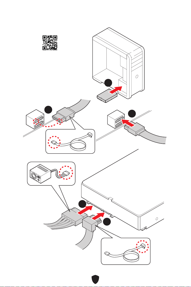
11
Installation des disques SATA
http://youtu.be/RZsMpqxythc
11
22
33
44
55

12
Installation d’une carte graphique
http://youtu.be/mG0GZpr9w_A
11
22
33
44
55
66

13
Connexion des périphériques

14
Allumer
44
33
11
22

15
Caractéristiques
CPU
Support des processeurs Intel® Core™ de 12ème et
13ème génération, Pentium® Gold et Celeron®*
Socket LGA1700
* Veuillez vous rendre sur le site www.msi.com pour obtenir la dernière liste
des modèles supportés à mesure que de nouveaux processeurs sont introduits
sur le marché.
Chipset Chipset Intel® Z790
Mémoire
4 x slots pour mémoire DDR5, support jusqu’à 128 Go*
Support 1R 5600 MHz (par JEDEC et POR)
Fréquence d’overclocking maximale :
• La fréquence maximale en mode 1DPC 1R monte
jusqu’à 7600+ MHz
• La fréquence maximale en mode 1DPC 2R monte
jusqu’à 6600+ MHz
• La fréquence maximale en mode 2DPC 1R monte
jusqu’à 6400+ MHz
• La fréquence maximale en mode 2DPC 2R monte
jusqu’à 5600+ MHz
Support Intel® XMP 3.0 OC
Support mémoire dual channel à double contrôleur
Support non-ECC, mémoire un-buffered
* Veuillez vous référer au site www.msi.com pour plus d’informations sur la
mémoire compatible.
Slots d’extension
2 x slots PCIe x16
• Slot PCI_E1 (depuis CPU)
• Support jusqu’à PCIe 5.0 x16*
• Slot PCI_E3 (depuis chipset Z790)
• Support jusqu’à PCIe 4.0 x4
1 x slot PCIe x1
• Slot PCI_E2 (depuis chipset Z790)
• Support jusqu’à PCIe 3.0 x1
* Le slot PCI_E1 fonctionne en mode x8 lorsqu’un SSD M.2 PCIe est installé dans
le slot M2_2.
Suite du tableau sur la page suivante

16
Suite du tableau sur la page précédente
Sorties vidéo
intégrées
1 x port HDMI™ 2.1 avec HDR, supportant une résolution
maximum de 4K 60 Hz*
/
**
* Disponible uniquement pour le processeur avec puce graphique intégrée.
** Les caractéristiques des cartes graphiques peuvent varier en fonction du
processeur installé.
Ports SATA
6 x ports SATA 6 Gb/s
• SATA5~8 (depuis chipset Z790)
• SATA_A1~A2 (depuis ASM1061)
Slots SSD M.2
5 x slots M.2 (Touche M)
• Slot M2_1 (depuis CPU)
• Support jusqu’à PCIe 4.0 x4
• Support des périphériques de stockage 2260/2280
• Slot M2_2 (depuis CPU)
• Support jusqu’à PCIe 5.0 x4
• Support des périphériques de stockage
2260/2280/22110
• Slot M2_3 (depuis chipset Z790)
• Support jusqu’à PCIe 4.0 x4
• Support des périphériques de stockage 2260/2280
• Slot M2_4 (depuis chipset Z790)
• Support jusqu’à PCIe 4.0 x4
• Support des périphériques de stockage 2260/2280
• Slot M2_5 (depuis chipset Z790)
• Support jusqu’à PCIe 4.0 x4
• Support jusqu’à SATA 6 Gb/s
• Support des périphériques de stockage 2260/2280
RAID
Support RAID 0, RAID 1, RAID 5 et RAID 10 pour les
périphériques de stockage SATA*
Support RAID 0, RAID 1, RAID 5 et RAID 10 pour les
périphériques de stockage M.2 NVMe
* SATA_A1~A2 ne supportent pas la fonction RAID.
Suite du tableau sur la page suivante

17
Suite du tableau sur la page précédente
Audio
Realtek® ALC4080 Codec
USB 7.1 audio haute performance
Support de la lecture jusqu’à 32 bits/384 kHz sur le
panneau avant.
Support sortie S/PDIF
LAN 1 x contrôleur Intel® 2.5Gbps LAN
Wi-Fi et Bluetooth®
Intel® Wi-Fi 6E
Le module sans-fil est pré-installé dans le slot M.2
(Touche E)
Support MU-MIMO TX/RX, 2,4 GHz / 5 GHz / 6 GHz* (160
MHz) jusqu’à 2,4 Gb/s
Support 802.11 a/b/g/n/ac/ax
Support Bluetooth® 5.3**, FIPS, FISMA
* La norme Wi-Fi 6E 6 GHz peut dépendre des réglementations de chaque pays
et sera disponible dans Windows 10 21H1 et Windows 11.
** La norme Bluetooth 5.3 sera disponible dans Windows 10 21H1 et Windows
11.
Connecteurs
d’alimentation
1 x connecteur d’alimentation principal ATX à 24 broches
2 x connecteurs d’alimentation 12 V à 8 broches
Connecteurs USB
internes
1 x port de panneau avant USB 3.2 Gen 2x2 20 Gb/s Type-C
(depuis chipset Z790)
1 x connecteur USB 3.2 Gen 1 5 Gb/s (depuis chipset Z790)
• Support de 2 autres ports USB 3.2 Gen 1 5 Gb/s
2 x connecteurs USB 2.0 (depuis Hub-GL850G)
• Support de 4 autres ports USB 2.0
Connecteurs de
ventilateur
1 x connecteur de ventilateur CPU à 4 broches
1 x connecteur de ventilateur à 4 broches pour la pompe
à eau
5 x connecteurs de ventilateur système à 4 broches
Suite du tableau sur la page suivante

18
Suite du tableau sur la page précédente
Connecteurs
système
1 x connecteur audio avant
2 x connecteurs de panneau système
1 x connecteur d’intrusion châssis
1 x connecteur de module TPM
1 x connecteur du contrôleur de réglages
1 x connecteur TBT (Support RTD3)
Cavaliers
1 x cavalier Clear CMOS
1 x cavalier de démarrage sécurisé
Fonctions LED
1 x interrupteur de commande EZ LED
1 x 2-Digit Debug Code LED
4 x EZ Debug LED
1 x connecteur LED RGB à 4 broches
2 x connecteurs LED A-RAINBOW V2 (ARGB Gen2) à 3
broches
Connecteurs sur le
panneau arrière
1 x bouton Clear CMOS
1 x bouton Flash BIOS
1 x bouton intelligent
2 x ports USB 3.2 Gen 1 5 Gb/s Type-A (depuis chipset
Z790)
1 x port HDMI™
6 x ports USB 3.2 Gen 2 10 Gb/s Type-A (depuis chipset
Z790 et Hub GL3590)
1 x prise LAN (RJ45)
1 x port USB 3.2 Gen 2 10 Gb/s Type-C (depuis chipset
Z790)
1 x port USB 3.2 Gen 2x2 20 Gb/s Type-C (depuis Asmedia
ASM3242)
2 x connecteurs d’antenne Wi-Fi
5 x prises audio
1 x connecteur de sortie S/PDIF optique
Contrôleur E/S Contrôleur NUVOTON NCT6687D-M
Suite du tableau sur la page suivante

19
Suite du tableau sur la page précédente
Moniteur système
Détection de la température du CPU, du système et du
chipset
Détection de la vitesse du ventilateur du CPU, du système
et de la pompe
Contrôle de la vitesse du ventilateur du CPU, du système
et de la pompe
Dimensions
Format ATX
30,5 cm x 24,4 cm (12” x 9,6”)
Fonctions BIOS
1 x flash 256 Mb
UEFI AMI BIOS
ACPI 6.4, SMBIOS 3.5
Multilingue
Logiciel
Pilotes
MSI Center
Intel Extreme Tuning Utility
MSI APP Player (BlueStacks)
CPU-Z MSI GAMING
Norton 360 Deluxe
AIDA64 Extreme - MSI Edition
Tile

20
Fonctions spéciales
MSI Center
• Gaming Mode
• Smart Priority
• Game Highlights
• Mystic Light
• Ambient Link
• Frozr AI Cooling
• User Scenario
• True Color
• Live Update
• Hardware Monitoring
• Super Charger
• Devices Speed Up
• Smart Image Finder
• MSI Companion
Caractéristiques du refroidissement
• Double-sided M.2 Shield Frozr
• Extended Heatsink Design Heat-pipe
• K7 MOSFET thermal pad / Extra
choke pad
• Fan headers (CPU + PUMP +
SYSTEM)
Performance
• Core Boost
• VRM Power Design (VCPU / VGT /
AUX)
• Dual CPU Power
• Memory Boost
• Lightning Gen 5 PCI-E / M.2 Slot
• Lightning Gen 4 PCI-E / M.2 Slot
• Front USB Type-C
• Server Grade PCB
• 2oz Copper thickened PCB
Pour le bricolage
• PCI-E Steel Armor
• Pre-installed I/O Shield
• Screwless M.2 Shield Frozr
• EZ M.2 Clips
• EZ DEBUG LED
• EZ LED Control
• Smart Button
• Bouton Flash BIOS
Audio
• Audio Boost 5
Support du rétroéclairage
• Mystic Light
• Mystic Light Extension (RGB)
• Mystic Light Extension (A-RAINBOW
V2)
• Ambient Link Support
BIOS
• Click BIOS 5

21
Contenu
Vérifiez tous les articles dans le carton d’emballage de votre carte mère. L’emballage
doit contenir :
Carte mère
• 1 x carte mère
Documentation
• 1 x guide d’installation rapide
• 1 x avis réglementaire de l’Union européenne
Application
• 1 x clé USB avec pilotes et utilitaires
Câble
• 2 x câbles SATA 6 Gb/s
• 1 x câble d’extension JRGB (1 à 2)
• 1 x câble d’extension JARGB
Accessoires
• 1 x set d’antenne Wi-Fi
• 4 x sets de clips EZ M.2 (1 set/paquet)
• 1 x autocollant de câble
Important
Il y a un fichier ISO dans la clé USB fournie. Veuillez ne pas le supprimer
accidentellement. Pour plus d’informations sur l’installation des pilotes, veuillez vous
référer au chapitre Installer le système d’exploitation, les pilotes et MSI Center.
Veuillez contacter votre revendeur si un des éléments ci-dessus est endommagé ou
manquant.—

22
Connecteurs de panneau arrière
Élément Description
1
Bouton Clear CMOS - Éteignez votre ordinateur. Appuyez sur le bouton
Clear CMOS pendant 5 à 10 secondes pour réinitialiser le BIOS aux
valeurs par défaut.
2
Port USB 3.2 Gen 1 5 Gb/s Type-A (depuis chipset Z790)
Port Flash BIOS
3 Port USB 3.2 Gen 1 5 Gb/s Type-A (depuis chipset Z790)
4 Ports USB 3.2 Gen 2 10 Gb/s Type-A (depuis chipset Z790)
5 Prise LAN (RJ45) 2,5 Gb/s
6 Connecteurs d’antenne Wi-Fi
7 Prises audio
8
Bouton Flash BIOS - Veuillez vous référer à la page 64 pour la mise à
jour du BIOS avec le bouton Flash BIOS.
11 77
88 101099 14141313
55 66
12121111
3322 44
23
Élément Description
9
Bouton intelligent - propose 4 fonctions. Veuillez vous référer au
manuel du BIOS pour plus de détails sur la sélection de la fonction de
bouton intelligent.
Réinitialiser (défaut) - appuyez sur le bouton intelligent pour
réinitialiser le système.
Mystic Light on/off - appuyez sur le bouton intelligent pour allumer/
éteindre toutes les LED embarquées. Le mode de fonction Mystic
Light on/off est indisponible lorsque l’interrupteur LED_SW1
(Contrôle EZ LED) est paramétré sur OFF.
Démarrage securisé - appuyez sur le bouton intelligent et
maintenez-le enfoncé pour démarrer le système simultanément en
mode de démarrage sécurisé. Le système démarrera par défaut et
abaissera le mode PCIe (depuis CPU).
Ventilateur Turbo - appuyez sur le bouton intelligent pour que tous
les ventilateurs fonctionnent à pleine vitesse ou à vitesse par défaut.
10
Port HDMI™
11 Ports USB 3.2 Gen 2 10 Gb/s Type-A (depuis Hub GL3590)
12 Port USB 3.2 Gen 2 10 Gb/s Type-C (depuis chipset Z790)
13 Port USB 3.2 Gen 2x2 20 Gb/s Type-C (depuis ASM3242)
14 Connecteur de sortie S/PDIF optique
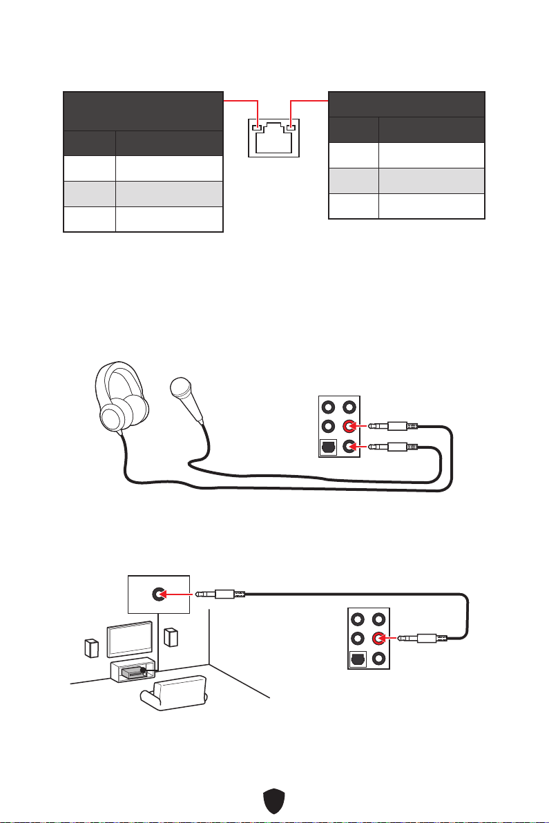
24
Tableau explicatif de l’état de la LED du port LAN
LED indiquant la connexion
et l’activité
État Description
Éteint Pas de connexion
Jaune Connexion correcte
Clignote Activité en cours
LED indiquant la vitesse
État Vitesse
Éteint 10 Mb/s
Vert 100/1000 Mb/s
Orange 2,5 Gb/s
Connexion des prises audio
Illustration de l’utilisation des ports audio dédiés au casque et au
microphone
Illustration de l’utilisation du port audio dédié aux haut-parleurs
AUDIO INPUT
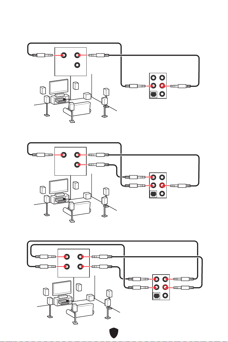
25
Illustration de l’utilisation des ports audio dédiés aux haut-
parleurs 7.1 canaux
Illustration de l’utilisation des ports audio dédiés aux haut-
parleurs 4 canaux
Illustration de l’utilisation des ports audio dédiés aux haut-
parleurs 5.1 canaux
AUDIO INPUT
Rear Front
Center/
Subwoofer
AUDIO INPUT
Rear Front
Center/
Subwoofer
AUDIO INPUT
Rear Front
Side Center/
Subwoofer

26
Installation des antennes
1. Combinez l’antenne avec la base.
2. Vissez fermement les antennes aux connecteurs d’antenne Wi-Fi comme indiqué
ci-dessous.
11
22
3. Placez les antennes le plus haut possible.

27
Vue d’ensemble des composants
CPU_FAN1
PUMP_FAN1
SYS_FAN5
SYS_FAN4
JARGB_V2_2
ATX_PWR1
JUSB4
JUSB3
Socket
processeur
CPU_PWR1
CPU_PWR2
DIMMA2
DIMMB1
DIMMB2
DIMMA1
JCI1
JFP1
JBAT1
JOCFS1
LED_SW1
SYS_FAN3
SYS_FAN2
SYS_FAN1
JDASH1
JPWRLED1
JTBT1
JARGB_V2_1
JRGB1
JAUD1
JUSB2
JUSB1
M2_5
M2_1
M2_2
M2_3
M2_4
PCI_E1
PCI_E2
PCI_E3
JFP2
JTPM1
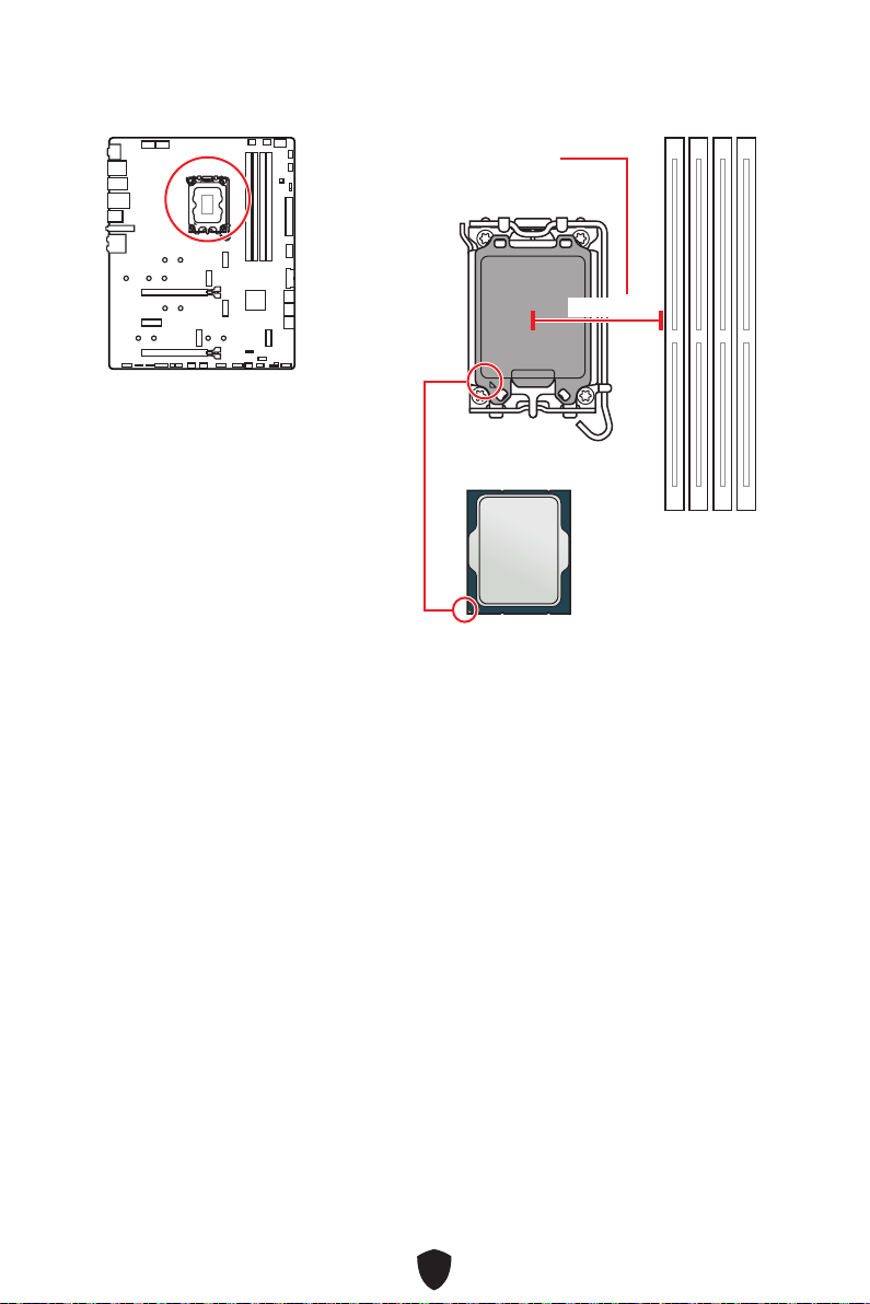
28
Important
Avant d’installer ou de retirer le processeur du socket, veillez à toujours débrancher
le câble d’alimentation de la prise électrique.
Veuillez garder le capot de protection du processeur après l’installation du
processeur. Selon les exigences de RMA (Return Merchandise Authorization), MSI
n’acceptera pas les cartes mère dont le capot de protection aura été retiré.
Lors de l’installation d’un processeur, n’oubliez pas d’installer un ventilateur
pour processeur. Un ventilateur de processeur est nécessaire pour protéger le
processeur contre la surchauffe et maintenir la stabilité du système.
Assurez-vous de l’étanchéité entre le ventilateur et le processeur avant de
démarrer votre système.
La surchauffe peut facilement endommager le processeur et la carte mère.
Assurez-vous toujours que le système de refroidissement fonctionne correctement
pour protéger le processeur de la surchauffe. Assurez-vous d’appliquer une couche
de pâte thermique (ou adhésif thermique) entre le processeur et le système de
refroidissement afin d’améliorer la dissipation de la chaleur.
Quand le processeur n’est pas installé, protégez toujours les broches du socket
CPU avec le couvercle dédié.
Si vous avez achetez un processeur indépendamment du ventilateur, veuillez vous
référer à la documentation dans le paquet du ventilateur pour plus d’informations
concernant l’installation.
Cette carte mère supporte l’overclocking. Néanmoins, veuillez vous assurer que vos
composants soient capables de tolérer l’overclocking. Prenez note que l’utilisation
au-delà des caractéristiques du constructeur n’est pas recommandée. MSI® ne
garantit pas les dommages et risques causés par les utilisations non prévues dans
les spécifications du produit.
Socket CPU
Présentation du socket
LGA1700
Sur le socket LGA1700, vous
remarquerez quatre encoches et un
triangle doré servant d’indicateurs pour
placer le processeur dans la bonne
position. Le triangle doré correspond à
la broche 1 du processeur.
Distance entre le centre du CPU
et le slot DIMM le plus proche.
50,85 mm

29
Slots DIMM
DIMMA1 DIMMB1
Canal A Canal B
DIMMA2 DIMMB2
Installation recommandée de module mémoire
Important
Veillez à toujours insérer un module de mémoire dans le slot DIMMA2 en premier.
Pour garantir la stabilité du système au mode de double canal, assurez-vous
d’installer les modules de mémoire du même type, du même nombre et de la même
densité.
Certaines mémoires peuvent fonctionner à une fréquence réduite par rapport à
la valeur indiquée lors de l’overclocking car la fréquence d’opération de mémoire
dépend du Serial Presence Detect (SPD). Rendez-vous sur le BIOS et choisissez la
fonction DRAM Frequency pour régler la fréquence de mémoire si vous voulez faire
fonctionner la mémoire à la fréquence indiquée ou à une fréquence plus élevée.
Il est recommandé d’utiliser un système de refroidissement qui sera capable de
refroidir toutes les barrettes mémoire et d’offrir de bonnes performances lors d’un
overclocking.
La stabilité et la compatibilité du module de mémoire lors de l’overclocking
dépendent du processeur et des périphériques installés.
Veuillez vous référer au site www.msi.com pour plus d’informations sur la mémoire
compatible.
DIMMA2 DIMMA2
DIMMB2
DIMMA1
DIMMA2
DIMMB1
DIMMB2

30
PCI_E1~3 : Slots d’extension PCIe
PCI_E1 : PCIe 5.0 x16 (depuis CPU)
PCI_E2 : PCIe 3.0 x1 (depuis chipset Z790)
PCI_E3 : PCIe 4.0 x4 (depuis chipset Z790)
Important
Si vous installez une carte graphique lourde, il vous faut utiliser un outil comme
la barre de support MSI pour supporter son poids et pour éviter la déformation du
slot.
Si vous choisissez d’installer une seule carte d’extension PCIe x16, nous vous
recommandons d’utiliser le slot PCI_E1 pour profiter de performances optimales.
Veillez à toujours mettre l’ordinateur hors tension et à débrancher le cordon
d’alimentation avant d’installer les cartes d’extension. Référez-vous à la
documentation des cartes pour vérifier si un composant ou un logiciel doit être
modifié.
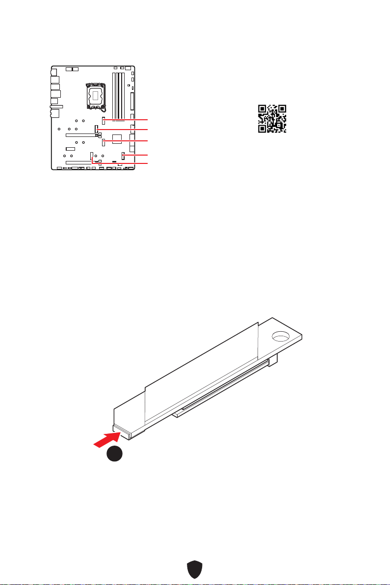
31
M2_1~5 : Slots M.2 (Touche M)
M2_1
M2_2
M2_4
M2_5
M2_3
Important
La technologie Intel® RST supporte uniquement un SSD M.2 PCIe avec une mémoire
ROM UEFI.
Si votre SSD M.2 dispose de son propre système de dissipation de chaleur, retirez
le plaque M.2 ou le cube en caoutchouc dan le slot M.2 avant d’installer le SSD M.2.
Veuillez ne pas réinstaller le dissipateur fourni avec votre carte mère.
Installation du module M.2 dans le slot M2_1
1. Appuyez sur le bouton de fin de la plaque Screwless M.2 Shield Frozr et
maintenez-le enfoncé.
11
https://youtu.be/J88vcXeLido
Regardez la vidéo pour savoir
comment installer le SSD M.2 avec la
plaque Scressless M.2 Shield Frozr.

32
2. Soulevez légèrement l’extrémité de la plaque Screwless M.2 Shield Frozr et
déplacez-la vers l’avant pour retirer la plaque.
22
3. Retirez le film de protection du pad thermique M.2 de la plaque M.2.
33
4. Si vous installez un SSD 2260, retirez la vis de la plaque M.2, puis installez le kit de
clips EZ M.2 fourni sur la plaque M.2. Ignorez cette étape si vous installez un SSD
2280.
44
SSD 2260

33
5. Insérez votre SSD M.2 dans le slot M.2 à un angle de 30 degrés.
6. Faites pivoter le clip EZ M.2 pour fixer le SSD M.2.
30º30º
30º30º
SSD 2280
SSD 2260
66
66
55
55
7. Retirez le film de protection du pad thermique sous la plaque Screwless M.2 Shield
Frozr.
8. Alignez les tenons sous la plaque Screwless M.2 Shield Frozr sur les encoches,
puis remettez la plaque en place.
9. Appuyez sur l’extrémité de la plaque Screwless M.2 Shield Frozr pour la verrouiller
complètement.
99
88
77

34
Installation du module M.2 dans le slot M2_2
1. Desserrez les vis de la plaque M2_1 SHIELD FROZR et enlevez la plaque.
11
11
2. Retirez le film de protection du pad thermique M.2 de la plaque M.2.
22
3. Retirez ou échangez les vis selon la longueur du SSD. Ignorez cette étape si vous
installez un SSD 2280.
33
33
SSD 22110
SSD 2260

35
4. Insérez votre SSD M.2 dans le slot M.2 à un angle de 30 degrés.
5. Faites pivoter le clip EZ M.2 pour fixer le SSD M.2.
30º30º
30º30º
SSD 22110
SSD 2280
SSD 2260
44
44
55
55
6. Retirez le film de protection du pad thermique sous la plaque M.2 Shield Frozr.
7. Remettez la plaque M.2 SHIELD FROZR en place et fixez-la.
66
77
77

36
Installation du module M.2 dans les slots M2_3/M2_4/M2_5
1. Desserrez les vis de la plaque M.2 SHIELD FROZR.
11
11
11
11
2. Retirez le film de protection du pad thermique M.2 de la plaque M.2.
22
3. Si vous installez un SSD 2260, retirez la vis de la plaque M.2, puis installez le kit de
clips EZ M.2 fourni sur la plaque M.2. Ignorez cette étape si vous installez un SSD
2280.
33
SSD 2260

37
4. Insérez votre SSD M.2 dans le slot M.2 à un angle de 30 degrés.
5. Faites pivoter le clip EZ M.2 pour fixer le SSD M.2.
30º30º
30º30º
SSD 2280
SSD 2260
55
44
44
55
6. Retirez le film de protection du pad thermique sous la plaque M.2 Shield Frozr.
7. Remettez la plaque M.2 Shield Frozr en place et fixez-la.
66
77
77 77
77
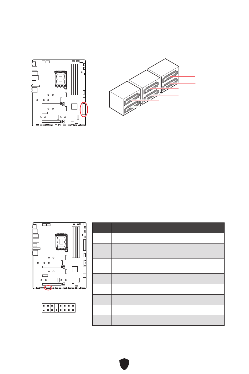
38
SATA5~8 et SATA_A1~A2 : Connecteurs SATA 6 Gb/s
Ces connecteurs utilisent une interface SATA 6 Gb/s. Chaque connecteur peut être
relié à un appareil SATA.
SATA5
SATA7
SATA_A1
SATA6
SATA8
SATA_A2
Important
Veuillez ne pas plier les câbles SATA à 90° car cela pourrait entraîner une perte de
données pendant la transmission.
Les câbles SATA disposent de prises identiques sur chaque côté. Néanmoins, il est
recommandé de connecter la prise plate sur la carte mère pour un gain d’espace.
JTBT1 : Connecteur de carte additionnelle Thunderbolt
Ce connecteur vous permet de relier une carte additionnelle Thunderbolt E/S.
1
2 16
15
Broche Nom de signal Broche Nom de signal
1 TBT_FORCE_PWR 2 TBT_S0IX_ENTRY_REQ
3
TBT_CIO_PLUG_
EVENT#
4 TBT_S0IX_ENTRY_ACK
5 SLP_S3#_TBT 6
TBT_PSON_
OVERRIDE_N
7 SLP_S5#_TBT 8 No Pin
9 Ground 10 SMBCLK_VSB
11 DG_PEWAKE# 12 SMBDATA_VSB
13 TBT_RTD3_PWR_EN 14 Ground
15 TBT_CARD_DET_R# 16 PD_IRQ#
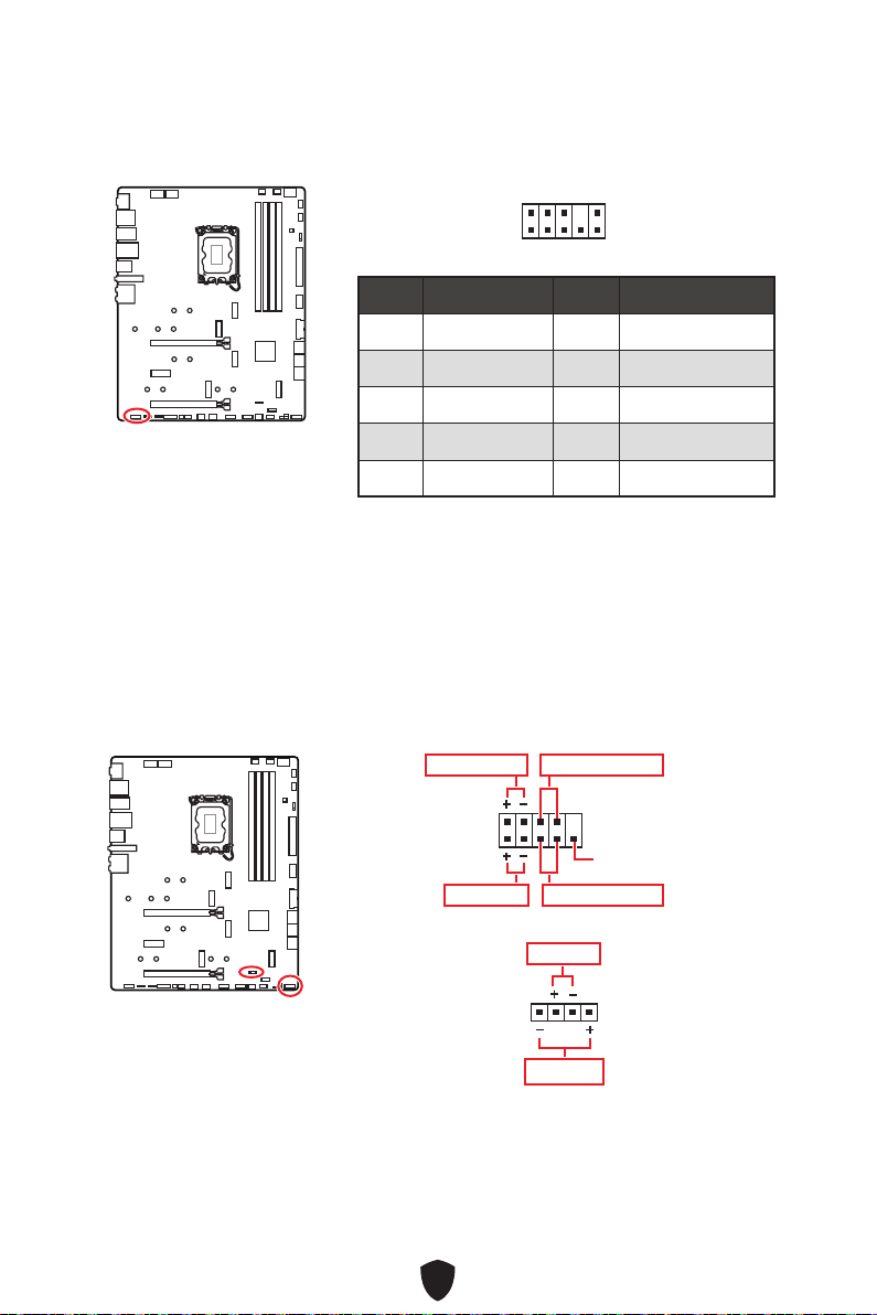
39
JAUD1 : Connecteur audio avant
Ce connecteur se lie aux prises audio du panneau avant.
1
2 10
9
Broche Nom de signal Broche Nom de signal
1 MIC L 2 Ground
3 MIC R 4 NC
5 Head Phone R 6 MIC Detection
7 SENSE_SEND 8 No Pin
9 Head Phone L 10 Head Phone Detection
JFP1, JFP2 : Connecteurs de panneau avant
Le connecteur JFP1 contrôle la mise sous tension, la réinitialisation de l’alimentation
et les LED du boîtier/châssis de votre PC. Les connecteurs Power Switch et Reset
Switch vous permettent de connecter le bouton d’alimentation et le bouton de
réinitialisation. Le connecteur Power LED se connecte à l’indicateur LED du boîtier du
PC et le connecteur HDD LED indique l’activité du disque dur. Le connecteur JFP2 est
destiné au buzzer et au haut-parleur. Pour connecter les câbles du boîtier du PC aux
bonnes broches, veuillez vous référer aux images suivantes ci-dessous.
1
2 10
9
Power LED
Reserved
Power Switch
JFP1
Reset SwitchHDD LED
1
JFP2
Buzzer
Speaker
Important
Veuillez noter que les connecteurs Power LED et HDD LED disposent d’un pôle négatif
et d’un pôle positif. Vous devez donc connecter le câble aux pôles positifs et négatifs
correspondants de la carte mère. Dans le cas contraire, les LED ne fonctionneront
pas correctement.

40
Important
Veuillez vous assurer que tous les câbles d’alimentation sont branchés aux
connecteurs adéquats afin de garantir une opération stable de la carte mère.
CPU_PWR1~2, ATX_PWR1 : Connecteurs d’alimentation
Ces connecteurs vous permettent de relier une alimentation ATX.
CPU_PWR1~2
Broche Nom de signal Broche Nom de signal
1 Ground 2 Ground
3 Ground 4 Ground
5 +12V 6 +12V
7 +12V 8 +12V
ATX_PWR1
Broche Nom de signal Broche Nom de signal
1 +3.3V 2 +3.3V
3 Ground 4 +5V
5 Ground 6 +5V
7 Ground 8 PWR OK
9 5VSB 10 +12V
11 +12V 12 +3.3V
13 +3.3V 14 -12V
15 Ground 16 PS-ON#
17 Ground 18 Ground
19 Ground 20 Res
21 +5V 22 +5V
23 +5V 24 Ground
5
4 1
8
CPU_PWR1~2
24
131
12
ATX_PWR1
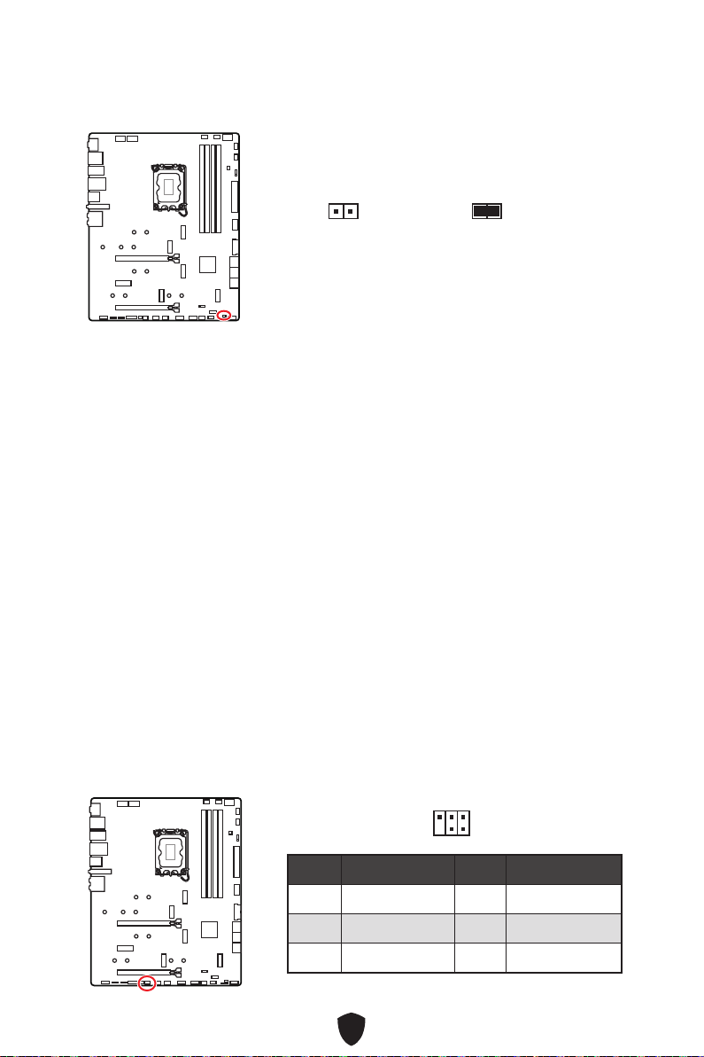
41
JCI1 : Connecteur d’intrusion châssis
Ce connecteur est relié à un câble d’interrupteur d’intrusion châssis.
Normal
(défaut)
Commencer l’activité
d’intrusion châssis
Utilisation du détecteur d’intrusion châssis
1. Reliez le connecteur JCI1 à l’interrupteur ou au capteur d’intrusion châssis situé
sur le boîtier du PC.
2. Fermez le couvercle du boîtier.
3. Allez dans BIOS > SETTINGS (Réglages) > Security (Sécurité) > Chassis Intrusion
Configuration (Configuration d’intrusion châssis).
4. Réglez Chassis Intrusion (Intrusion châssis) sur Enabled (Activé).
5. Appuyez sur F10 pour sauvegarder et quitter. Ensuite appuyez sur la touche Enter
(Entrée) pour choisir Yes (Oui).
6. Désormais, si le boîtier du PC est ouvert quand l’ordinateur est allumé, vous
recevrez un message d’avertissement à l’écran.
Réinitialisation de l’avertissement d’intrusion châssis
1. Allez dans BIOS > SETTINGS (Réglages) > Security (Sécurité) > Chassis Intrusion
Configuration (Configuration d’intrusion châssis).
2. Réglez Chassis Intrusion (Intrusion châssis) sur Reset (Réinitialiser).
3. Appuyez sur F10 pour sauvegarder et quitter. Ensuite appuyez sur la touche Entrée
pour choisir Yes (Oui).
JDASH1 : Connecteur du contrôleur de réglages
Ce connecteur est utilisé pour connecter un contrôleur de réglage (selon modèle).
Broche Nom de signal Broche Nom de signal
1 No Pin 2 NC
3
MCU_SMB_SCL_M
4 MCU_SMB_SDA_M
5 VCC5 6 Ground
1
2
5
6
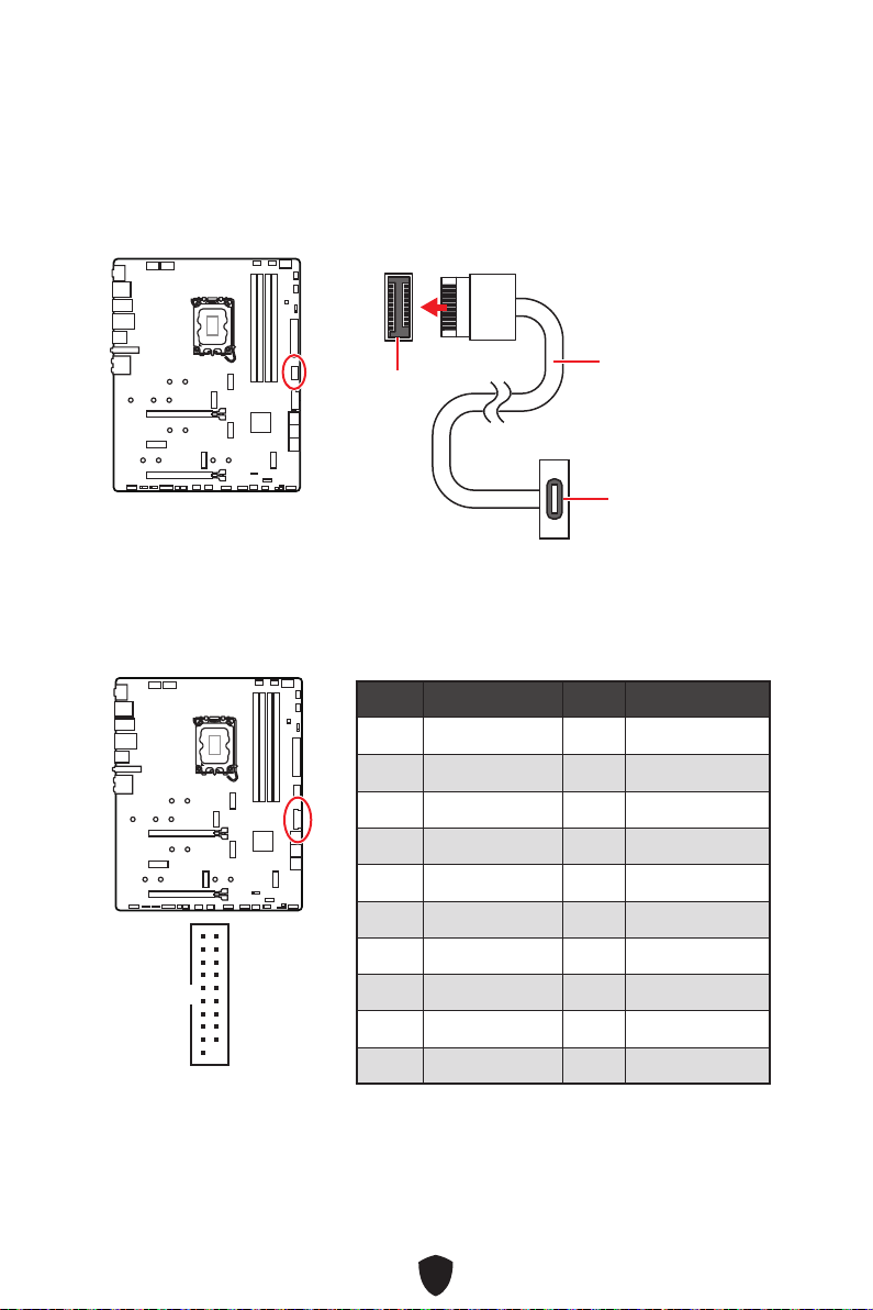
42
JUSB3 : Connecteur USB 3.2 Gen 1
Ce connecteur vous permet de relier un port USB 3.2 Gen 1 5 Gb/s sur le panneau
avant.
Important
Notez que les câbles d’alimentation et de terre doivent être branchés correctement
afin d’éviter d’endommager la carte.
JUSB4 : Connecteur de panneau avant USB 3.2 Gen 2x2
Type-C
Ce connecteur vous permet de relier un connecteur USB 3.2 Gen 2x2 20 Gb/s Type-C
sur le panneau avant. Pour plus de sécurité, ce connecteur a été conçu pour offrir une
excellente robustesse. Quand vous connectez le câble, assurez-vous de le brancher
dans le bon sens.
JUSB4
Câble USB Type-C
Port USB Type-C
sur le panneau
avant
Broche Nom de signal Broche Nom de signal
1 Power 2 USB3_RX_DN
3 USB3_RX_DP 4 Ground
5 USB3_TX_C_DN 6 USB3_TX_C_DP
7 Ground 8 USB2.0-
9 USB2.0+ 10 Ground
11 USB2.0+ 12 USB2.0-
13 Ground 14 USB3_TX_C_DP
15 USB3_TX_C_DN 16 Ground
17 USB3_RX_DP 18 USB3_RX_DN
19 Power 20 No Pin
1
10 11
20

43
JUSB1~2 : Connecteurs USB 2.0
Ces connecteurs vous permettent de relier des ports USB 2.0 sur le panneau avant.
Important
Notez que les broches VCC et Terre doivent être branchées correctement afin
d’éviter tout dommage sur la carte mère.
Pour recharger votre iPad, iPhone et iPod par l’intermédiaire d’un port USB, veuillez
installer l’utilitaire MSI Center.
JTPM1 : Connecteur de module TPM
Ce connecteur est relié à un module TPM (Trusted Platform Module). Veuillez vous
référer au manuel du module TPM pour plus d’informations.
Broche Nom de signal Broche Nom de signal
1 VCC 2 VCC
3 USB0- 4 USB1-
5 USB0+ 6 USB1+
7 Ground 8 Ground
9 No Pin 10 NC
1
2 10
9
Broche Nom de signal Broche Nom de signal
1 SPI Power 2 SPI Chip Select
3
Master In Slave Out
(SPI Data)
4
Master Out Slave In
(SPI Data)
5 Reserved 6 SPI Clock
7 Ground 8 SPI Reset
9 Reserved 10 No Pin
11 Reserved 12 Interrupt Request
1
2 12
11

44
CPU_FAN1, PUMP_FAN1, SYS_FAN1~5 : Connecteurs
de ventilateur
Les connecteurs de ventilateur peuvent être utilisés en mode PWM (Pulse Width
Modulation) et en mode DC. En mode PWM, les connecteurs fournissent une sortie
de 12 V constante et ajustent la vitesse du ventilateur avec un signal de contrôle de
vitesse. En mode DC, les connecteurs contrôlent la vitesse du ventilateur en modifiant
la tension. Le mode automatique détectera automatiquement le type de ventilateur
utilisé.
Vous pouvez contrôler les ventilateurs dans le panneau BIOS > HARDWARE MONITOR.
Il vous permet de régler DC ou PWM selon votre type de ventilateur. Si vous cochez
le Mode ventilateur intelligent, la vitesse du ventilateur changera en fonction de la
température du processeur ou du système. Si vous décochez le Mode ventilateur
intelligent, le ventilateur tournera à la vitesse maximale.
Important
Veuillez vous assurer que les ventilateurs fonctionnent correctement après avoir
basculé entre les modes PWM et DC.
CPU_FAN1
SYS_FAN2
SYS_FAN1
SYS_FAN3
PUMP_FAN1
SYS_FAN5
SYS_FAN4
1
Définition des broches en mode PWM
Broche Nom de signal Broche Nom de signal
1 Ground 2 +12V
3 Sense 4 Speed Control Signal
Définition des broches en mode DC
Broche Nom de signal Broche Nom de signal
1 Ground 2 Voltage Control
3 Sense 4 NC
Caractéristiques du connecteur de ventilateur
Connecteur
Mode ventilateur par
défaut
Courant maximum Puissance maximum
CPU_FAN1 Mode Auto 2 A 24 W
PUMP_FAN1 Mode PWM 3 A 36 W
SYS_FAN1~5 Mode DC 1 A 12 W
1
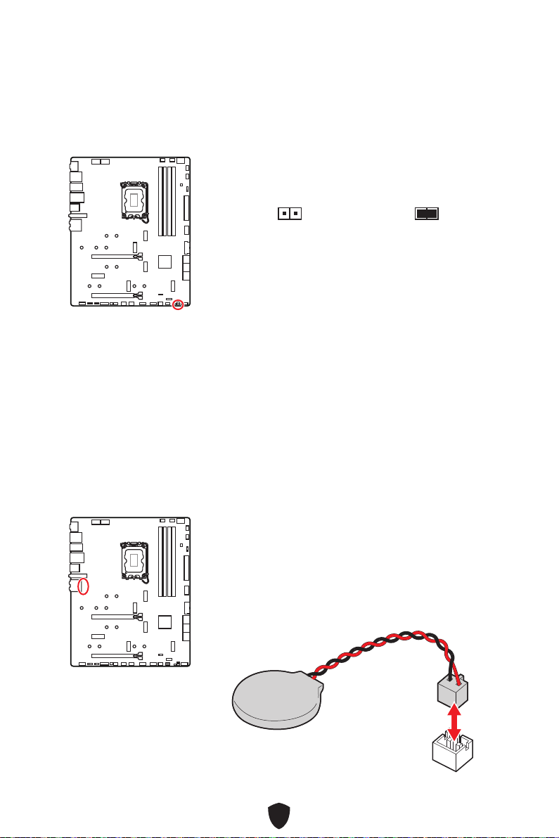
45
JBAT1 : Cavalier Clear CMOS (Réinitialiser le BIOS)
Une mémoire CMOS est intégrée et est alimentée en externe par une batterie située
sur la carte mère afin de conserver les données de configuration système. Si vous
souhaitez effacer la configuration du système, réglez le cavalier pour effacer la
mémoire CMOS.
BAT1 : Pile CMOS
Si la pile CMOS est déchargée, l’heure dans le BIOS sera réinitialisée et les données
de configuration du système seront perdues. Dans ce cas, vous devez remplacer la
pile CMOS.
Conserver
les données
(défaut)
Effacer le CMOS/
Réinitialiser le BIOS
Réinitialiser le BIOS aux valeurs par défaut
1. Éteignez l’ordinateur et débranchez le câble d’alimentation.
2. Utilisez un couvercle de cavalier pour fermer JBAT1 pendant 5 à 10 secondes.
3. Enlevez le couvercle de cavalier du JBAT1.
4. Branchez de nouveau le câble d’alimentation à votre ordinateur et allumez-le.
Remplacement de la pile CMOS
1. Débranchez le câble de la pile du connecteur BAT1 et
retirez la pile.
2. Connectez la nouvelle pile CR2032 avec le câble au
connecteur BAT1.
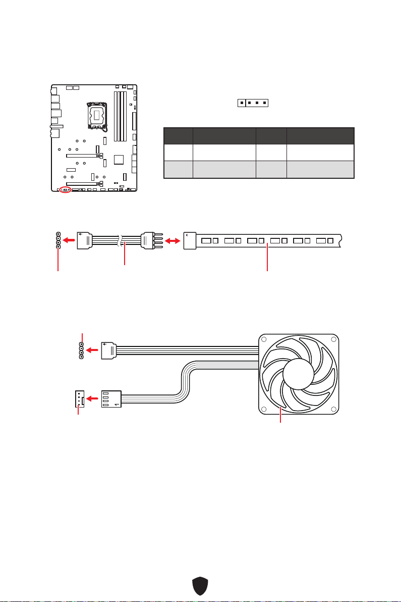
46
Important
Le connecteur JRGB supporte des rubans LED RGB (12 V/G/R/B) de type 5050 d’une
longueur de 2 mètres maximum avec une puissance nominale maximale de 3 A (12 V).
Avant d’installer ou de retirer le ruban LED RGB, veillez à toujours éteindre
l’alimentation et à débrancher le câble d’alimentation de la prise électrique.
Veuillez utiliser un logiciel MSI dédié pour contrôler le ruban d’extension LED.
JRGB1 : Connecteur LED RGB
Le connecteur JRGB vous permet de connecter un ruban LED RGB de type 5050 12 V.
1
G
R
B
Connecteur JRGB
Câble d’extension JRGB
Ruban LED RGB de type 5050 12 V
Connexion du ruban LED RGB
1
1
G
R
B
Connecteur JRGB
Connecteur de ventilateur système
Connexion du ventilateur LED RGB
Ventilateur LED RGB
Broche Nom de signal Broche Nom de signal
1 +12V 2 G
3 R 4 B
1

47
JARGB_V2_1~2 : Connecteurs LED A-RAINBOW V2 (ARGB
Gen2)
Les connecteurs JARGB_V2 vous permettent de connecter les rubans LED ARGB
Gen2 et ARGB. Le connecteur JARGB_V2 supporte jusqu’à 240 LED RGB adressables
individuellement avec une puissance nominale maximale de 3 A (5 V).
Broche Nom de signal Broche Nom de signal
1 +5V 2 Data
3 No Pin 4 Ground
1
1
1
1
1
D
+5V
Connecteur JARGB_V2
Connecteur JARGB_V2
Connecteur de ventilateur système
Câble d’extension JARGB
Ruban LED ARGB/ARGB Gen2
Connexion du ruban LED RGB adressable
Connexion du ventilateur LED RGB adressable
Ventilateur LED ARGB/ARGB Gen2

48
Attention
Faites attention à bien connecter le bon type de ruban LED. Le connecteur JRGB et le
connecteur JARGB_V2 fournissent des tensions différentes. La connexion d’un ruban
LED ARGB 5 V au connecteur JRGB peut endommager le ruban.
Important
Si vous connectez les rubans LED ARGB Gen1 et ARGB Gen2 au même connecteur,
cela peut entraîner des problèmes. Ne mélangez pas les rubans LED ARGB Gen1 et
ARGB Gen2.
Afin d’obtenir les meilleurs effets, nous vous recommandons fortement d’installer
des rubans LED proposant les mêmes caractéristiques.
Avant d’installer ou de retirer le ruban LED RGB adressable, veillez à toujours
éteindre l’alimentation et à débrancher le câble d’alimentation de la prise
électrique.
Veuillez utiliser un logiciel MSI dédié pour contrôler le ruban d’extension LED.
Normal
(défaut)
Démarrez avec les
paramètres BIOS
enregistrés.
Activé
Appliquer les
paramètres par défaut
du BIOS et le mode
PCIe inférieur (depuis
CPU) pour le démarrage
sécurisé.
JOCFS1 : Cavalier de démarrage sécurisé
Ce cavalier est utilisé pour le démarrage sécurisé. Une fois activé, le système
démarrera avec les paramètres par défaut et le mode PCIe inférieur (depuis CPU).
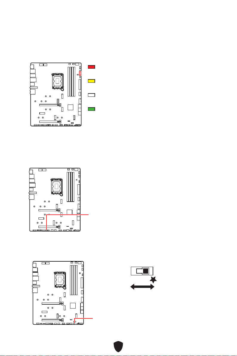
49
EZ Debug LED
Ces LEDs indiquent l’état de débogage de la carte mère.
CPU - indique que le CPU n’est pas détecté ou que
son initialisation a échoué.
DRAM - indique que la mémoire DRAM n’est pas
détectée ou que son initialisation a échoué.
VGA - Indique que les périphériques GPU ne sont pas
détectés ou que leur initialisation a échoué.
BOOT - indique que le périphérique de démarrage
n’est pas détecté ou que son initialisation a
échoué.
LED embarquées
JPWRLED1 : Indicateur LED de l’entrée d’alimentation
Ce connecteur est utilisé par les revendeurs pour faire une démonstration des effets
de lumière des indicateurs LED.
JPWRLED1 - Indicateur LED de l’entrée d’alimentation
LED_SW1 : Contrôle EZ LED
Cet interrupteur est utilisé pour allumer et éteindre toutes les LED de la carte mère.
LED_SW1
LED_OFF
LED_ON
(Défaut)
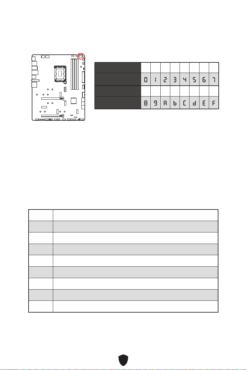
50
Debug Code LED
Le Debug Code LED affiche la progression et les codes d’erreur pendant et après le
POST. Veuillez vous référer au tableau du Debug Code LED pour plus de détails.
Phase de démarrage
Sécurité (SEC) - initialisation de très bas niveau
Initialisation Pre-EFI (PEI) – initialisation de la mémoire
Environnement d’exécution des pilotes (DXE) – initialisation du matériel principal
Sélection du périphérique de démarrage (BDS) – la configuration du système,
l’interface d’utilisateur de pré-OS et la sélection d’un périphérique amorçable (CD/
DVD, disque dur, USB, réseau, interface système, etc.)
Tableau du Debug Code LED
Codes de progression SEC
01 Sous tension. Détection du type de réinitialisation (soft/hard)
02 Initialisation AP avant chargement du microcode
03 Initialisation de l’agent système avant chargement du microcode
04 Initialisation PCH avant chargement du microcode
06 Chargement du microcode
07 Initialisation AP après chargement du microcode
08 Initialisation de l’agent système après chargement du microcode
09 Initialisation PCH après chargement du microcode
0B Initialisation du cache
Tableau des caractères hexadécimaux
Hexadécimaux 0 1 2 3 4 5 6 7
Affichage LED
Hexadécimaux 8 9 A B C D E F
Affichage LED
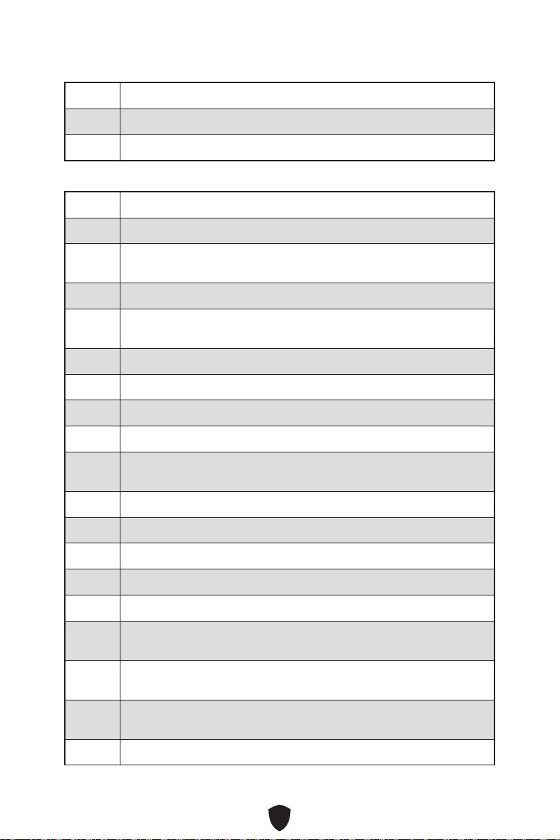
51
Codes d’erreur SEC
0C - 0D Réservé aux futurs codes d’erreur AMI SEC
0E Microcode introuvable
0F Microcode non chargé
Codes de progression PEI
10 Le cœur PEI est lancé
11 Initialisation de la pré-mémoire du processeur est lancée
12 - 14 Initialisation de la pré-mémoire du processeur (module processeur
spécifique)
15 Initialisation de la pré-mémoire de l’agent système est lancée
16 - 18 Initialisation de la pré-mémoire de l’agent système (module agent
système spécifique)
19 Initialisation de la pré-mémoire du PCH est lancée
1A - 1C Initialisation de la pré-mémoire du PCH (module PCH spécifique)
2B Initialisation de la mémoire. Lecture des données SPD
2C Initialisation de la mémoire. Détection de présence de la mémoire
2D Initialisation de la mémoire. Information sur la programmation de
synchronisation de la mémoire
2E Initialisation de la mémoire. Configuration de la mémoire
2F Initialisation de la mémoire (autre)
31 Mémoire installée
32 Initialisation de la post-mémoire du processeur est lancée
33 Initialisation de la post-mémoire du processeur. Initialisation du cache
34 Initialisation de la post-mémoire du processeur. Initialisation du ou des
processeurs d’application (AP)
35 Initialisation de la post-mémoire du processeur. Sélection du
processeur d’amorçage (BSP)
36 Initialisation de la post-mémoire du processeur. Initialisation du mode
de gestion du système (SMM)
37 Initialisation de la post-mémoire de l’agent système est lancée
52
38 - 3A Initialisation de la post-mémoire de l’agent système (module agent
système spécifique)
3B Initialisation de la post-mémoire du PCH est lancée
3C - 3E Initialisation de la post-mémoire du PCH (module PCH spécifique)
4F DXE IPL est lancé
Codes d’erreur PEI
50 Erreur d’initialisation de la mémoire. Type de mémoire invalide ou
vitesse de mémoire incompatible
51 Erreur d’initialisation de la mémoire. La lecture du SPD a échoué
52 Erreur d’initialisation de la mémoire. Taille de mémoire invalide ou
modules de mémoire incompatibles
53 Erreur d’initialisation de la mémoire. Aucune mémoire utilisable n’est
détectée
54 Erreur d’initialisation de la mémoire non spécifiée
55 Mémoire non installée
56 Type de processeur ou vitesse invalide
57 Le processeur ne correspond pas
58 Echec de l’auto-test du processeur ou possibilité d’erreur du cache du
processeur
59 Le microcode du processeur est introuvable ou la mise à jour du
microcode a échoué
5A Erreur du processeur interne
5B La réinitialisation PPI n’est pas disponible
5C - 5F Réservé aux futurs codes d’erreur AMI
Codes de progression DXE
60 Le cœur DXE est lancé
61 Initialisation NVRAM
62 Installation des services d’exécution du PCH
63 Initialisation du processeur DXE est lancée
64 - 67 Initialisation du processeur DXE (module processeur spécifique)

53
68 Initialisation du pont hôte PCI
69 Initialisation de l’agent système DXE est lancée
6A Initialisation de l’agent système DXE SMM est lancée
6B - 6F Initialisation de l’agent système DXE (module agent système spécifique)
70 Initialisation du PCH DXE est lancée
71 Initialisation du PCH DXE SMM est lancée
72 Initialisation des périphériques du PCH
73 - 77 Initialisation du PCH DXE (module PCH spécifique)
78 Initialisation du module ACPI
79 Initialisation CSM
7A - 7F Réservé aux futurs codes AMI DXE
90 La phase de sélection du périphérique de démarrage (BDS) est lancée
91 La connexion du pilote est lancée
92 Initialisation du bus PCI est lancée
93 Initialisation du contrôleur de branchement à chaud du bus PCI
94 Enumération du bus PCI 32
95 Demande des ressources du bus PCI
96 Distribution des ressources du bus PCI
97 Connexion du périphérique de sortie de console
98 Connexion du périphérique d’entrée de console
99 Initialisation Super IO
9A Initialisation USB est lancée
9B Réinitialisation USB
9C Détection USB
9D Activer USB
9E - 9F Réservé aux futurs codes AMI
A0 Initialisation IDE est lancée
54
A1 Réinitialisation IDE
A2 Détection IDE
A3 Activer IDE
A4 Initialisation SCSI est lancée
A5 Réinitialisation SCSI
A6 Détection SCSI
A7 Activer SCSI
A8 Configuration de vérification du mot de passe
A9 Démarrage de la configuration
AB Configuration de l’attente d’entrée
AD Evénement Prêt à démarrer
AE Evénement de démarrage du mode Legacy Boot (Démarrage hérité)
AF Quitter l’événement des services de démarrage
B0 Début de temps de définition d’adresse virtuelle MAP
B1 Fin de temps de définition d’adresse virtuelle MAP
B2 Initialisation des options Legacy de la mémoire ROM
B3 Réinitialisation du système
B4 Branchement à chaud de la USB
B5 Branchement à chaud du bus PCI
B6 Nettoyage de la NVRAM
B7 Réinitialisation de la configuration (réinitialisation des paramètres
NVRAM)
B8 - BF Réservé aux futurs codes AMI
Codes d’erreur DXE
D0 Erreur d’initialisation du processeur
D1 Erreur d’initialisation de l’agent système
D2 Erreur d’initialisation du PCH
55
D3 Certains protocoles architecturaux ne sont pas disponibles
D4 Erreur d’allocation des ressources PCI. Manque de ressources
D5 Aucun espace pour les options Legacy de la mémoire ROM
D6 Aucun périphérique de sortie de console n’est trouvé
D7 Aucun périphérique d’entrée de console n’est trouvé
D8 Mot de passe invalide
D9 Erreur lors du chargement de l’option de démarrage (erreur LoadImage)
DA Echec de l’option de démarrage (erreur StartImage)
DB Echec de la mise à jour du flash
DC Le protocole de réinitialisation n’est pas disponible
Codes de progression de reprise S3
E0 La reprise S3 est lancée (le PPI de reprise S3 est appelé par le DXE IPL)
E1 Exécution du Boot Script S3
E2 Reposter la vidéo
E3 Appel du vecteur d’éveil S3 du système d’exploitation
E4 - E7 Réservé aux futurs codes de prograssion AMI
Codes d’erreur de reprise S3
E8 Echec de reprise S3
E9 Reprise S3 PPI introuvable
EA Erreur de script de reprise démarrage S3
EB Erreur de réveil du système d’exploitation S3
EC - EF Réservé aux futurs codes d’erreur AMI
Codes de progression de la récupération
F0 Condition de récupération déclenchée par le firmware (récupération
automatique)
F1 Condition de récupération déclenchée par l’utilisateur (récupération
forcée)
56
F2 Le processus de récupération est lancé
F3 L’image de la récupération du firmware est trouvée
F4 L’image de la récupération du firmware est chargée
F5 - F7 Réservé aux futurs codes de prograssion AMI
Codes d’erreur de récupération
F8 La récupération PPI n’est pas disponible
F9 La capsule de récupération est introuvable
FA Capsule de récupération invalide
FB - FF Réservé aux futurs codes d’erreur AMI
Codes d’état ACPI
Les codes suivants apparaissent après le démarrage et après l’entrée du système
d’exploitation en mode ACPI.
01 Le système entre en état de veille S1
02 Le système entre en état de veille S2
03 Le système entre en état de veille S3
04 Le système entre en état de veille S4
05 Le système entre en état de veille S5
10 Le système sort de l’état de mode veille S1
20 Le système sort de l’état de mode veille S2
30 Le système sort de l’état de mode veille S3
40 Le système sort de l’état de mode veille S4
AC Le système est passé en mode ACPI. Le contrôleur d’interruption est en
mode PIC.
AA Le système est passé en mode ACPI. Le contrôleur d’interruption est en
mode APIC.
Température du processeur
00 - 99 Affiche la température du processeur après le démarrage complet du
système d’exploitation.

57
Installer OS, Pilotes et MSI Center
Veuillez vous référer au site www.msi.com pour télécharger et mettre à jour les
derniers utilitaires et pilotes.
Installer Windows 10/Windows 11
1. Allumez l’ordinateur.
2. Insérez le disque ou la clé USB d’installation de Windows 10/Windows 11 dans
votre ordinateur.
3. Appuyez sur le bouton Redémarrer (Restart) du boîtier de l’ordinateur.
4. Appuyez sur la touche F11 pendant le POST (Power-On Self Test) du système pour
entrer dans le menu de démarrage.
5. Choisissez le disque ou la clé USB d’installation de Windows 10/Windows 11 dans
le menu de démarrage.
6. Appuyez sur n’importe quelle touche lorsqu’apparaît le message [Appuyez sur
n’importe quelle touche pour démarrer du CD ou du DVD] (Press any key to boot
from CD or DVD). Sinon, veuillez ignorer cette étape.
7. Suivez les instructions à l’écran pour installer Windows 10/Windows 11.
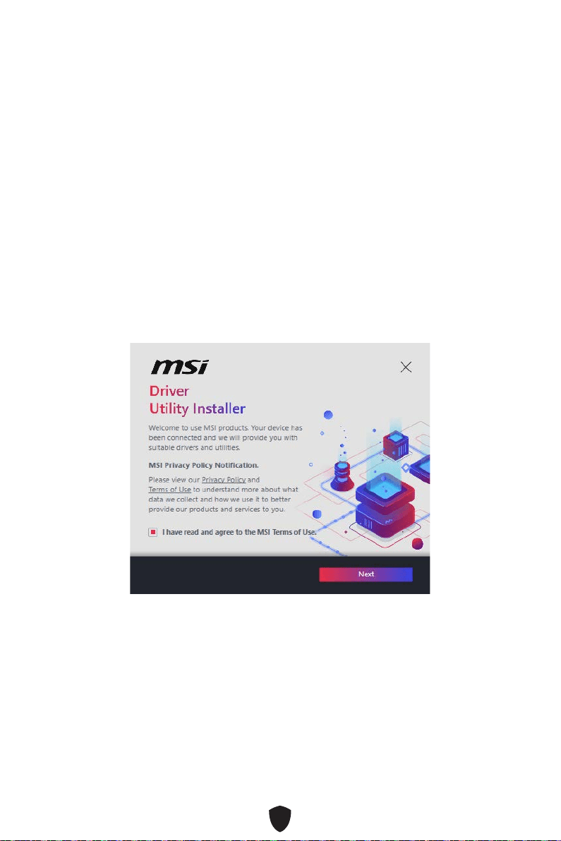
58
Installer les pilotes avec MSI Driver Utility Installer
Important
Certaines nouvelles puces réseau ne sont pas prises en charge par Windows 10/
Windows 11. Il est recommandé d’installer le pilote LAN avant d’installer les pilotes
avec MSI Driver Utility Installer. Veuillez vous référer au site www.msi.com pour
installer le pilote LAN adapté à votre carte mère.
Le MSI Driver Utility Installer n’apparaîtra qu’une seule fois. Si vous l’annulez ou
le fermez pendant le processus, veuillez vous référer au chapitre Live Update du
manuel MSI Center pour installer les pilotes. Vous pouvez également vous rendre
sur le site www.msi.com pour rechercher votre carte mère et télécharger les
pilotes.
MSI Driver Utility Installer doit être installé via Internet.
1. Allumez l’ordinateur sous Windows 10/Windows 11.
2. Sélectionnez Démarrer (Start) > Paramètres (Settings) > Windows Update, puis
sélectionnez Rechercher les mises à jour.
3. MSI Driver Utility Installer apparaîtra automatiquement.
4. Cochez la case J’ai lu et j’accepte les conditions d’utilisation de MSI (I have read
and agree to the MSI Terms of Use), puis cliquez sur Suivant (Next).
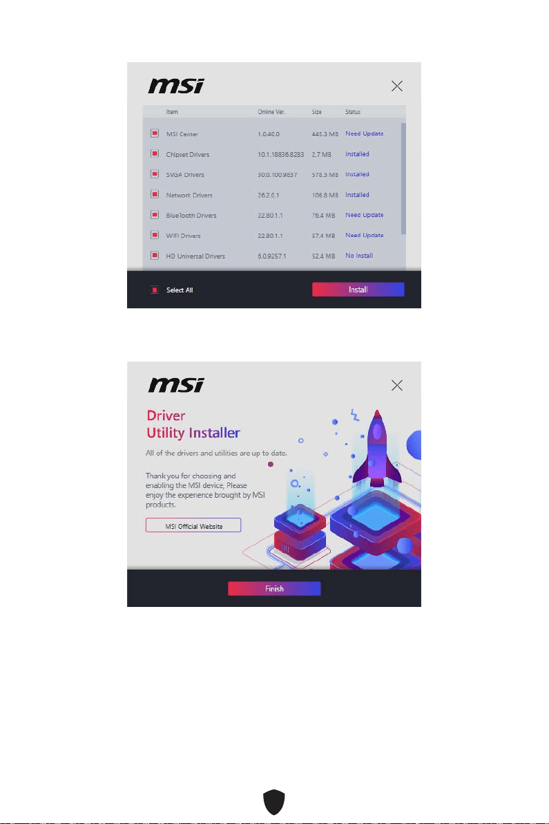
59
5. Cochez la case Sélectionner tout (Select All) dans le coin inférieur gauche
et cliquez sur Installer (Install) pour installer MSI Center et les pilotes. La
progression de l’installation sera affichée en bas.
6. Une fois la progression terminée, cliquez sur Terminer (Finish).
60
Installer les pilotes avec la clé USB MSI
1. Allumez l’ordinateur sous Windows 10/Windows 11.
2. Insérez la clé USB MSI dans le port USB.
3. Vous pouvez voir un fichier d’image disque contenant des pilotes et des utilitaires
sur la clé USB. Double-cliquez sur le fichier pour l’ouvrir.
4. Exécutez un fichier d’application nommé DVDSetup.
5. L’outil d’installation trouvera et listera tous les pilotes dont vous avez besoin dans
l’onglet Pilotes/Logiciels (Drivers/Software).
6. Cliquez sur le bouton Installer (Install) dans le coin inférieur droit de la fenêtre.
7. L’installation des pilotes commence. Une fois terminée, il vous sera demandé de
redémarrer.
8. Cliquez sur le bouton OK pour terminer.
9. Redémarrez votre ordinateur.
MSI Center
MSI Center est une application qui vous aide à optimiser facilement les paramètres
de jeu et à utiliser les logiciels de création de contenu de manière intuitive. Elle vous
permet également de contrôler et de synchroniser les effets de lumière LED sur les
PC et autres produits MSI. Avec MSI Center, vous pouvez personnaliser les modes
selon vos envies, surveiller les performances du système et régler la vitesse du
ventilateur.
Guide d’utilisation de MSI Center
Si vous souhaitez en savoir plus sur MSI Center, veuillez vous référer au
fichier
http://download.msi.com/manual/mb/MSICENTER.pdf
ou scannez le code QR pour y accéder.
Important
Les fonctions peuvent varier en fonction du produit que vous possédez.

61
UEFI BIOS
Le BIOS UEFI de MSI est compatible avec l’architecture UEFI (Unified Extensible
Firmware Interface). Le BIOS UEFI présente de nombreuses nouvelles fonctionnalités
et avantages qui ne sont pas proposés par le BIOS traditionnel. Le BIOS UEFI est ainsi
voué à totalement remplacer le BIOS traditionnel à l’avenir. Le BIOS UEFI de MSI
utilise UEFI comme mode de démarrage par défaut pour profiter au maximum des
capacités du nouveau chipset.
Important
Dans ce guide d’utilisation, le terme BIOS se réfère au BIOS UEFI, sauf indication
contraire.
Avantages de l’UEFI
Démarrage rapide - L’UEFI peut démarrer directement le système d’exploitation
et enregistrer le processus d’autotest du BIOS. Il élimine également le temps à
attendre pour passer en mode CSM pendant le POST.
Prend en charge des partitions de disque dur supérieures à 2 To.
Prend en charge plus de 4 partitions principales avec une table de partition GUID
(GPT).
Prend en charge un nombre illimité de partitions.
Prend en charge toutes les capacités de nouveaux appareils - les nouveaux
appareils peuvent ne pas fournir de compatibilité descendante.
Prend en charge le démarrage sécurisé - L’UEFI peut vérifier la validité du système
d’exploitation pour s’assurer qu’aucun malware ne perturbe le processus de
démarrage.
Cas d’incompatibilité avec l’UEFI
Système d’exploitation Windows 32 bits - cette carte mère supporte uniquement le
système d’exploitation Windows 10/Windows 11 64 bits.
Carte graphique ancienne - le système détectera votre carte graphique. Si vous
utilisez des cartes graphiques plus anciennes, un message d’avertissement peut
apparaître Il n’y a pas de support GOP (Graphics Output Protocol) détecté sur cette
carte graphique.
Important
Nous vous recommandons de remplacer votre carte graphique par un modèle
compatible GOP/UEFI ou d’utiliser un processeur avec puce graphique intégrée pour
profiter d’un fonctionnement normal.
Comment vérifier le mode BIOS ?
1. Allumez votre ordinateur.
2. Pendant le démarrage, lorsqu’apparaît le message Press DEL key to enter Setup
Menu, F11 to enter Boot Menu sur l’écran, veuillez appuyer sur la touche Suppr.
3. Après être entré dans le BIOS, vous pouvez vérifier le Mode BIOS en haut de
l’écran.
BIOS Mode: UEFI

62
Configuration du BIOS
Les réglages par défaut fournissent une performance optimale pour la stabilité du
système en conditions normales. Veillez à toujours garder les réglages par défaut
pour éviter d’endommager le système ou tout problème au démarrage, sauf si vous
êtes familier avec le BIOS.
Important
Le BIOS est constamment mis à jour afin d’offrir de meilleures performances du
système. Par conséquent, la description peut différer selon la version du BIOS
utilisée et n’est donc donnée qu’à titre de référence. Vous pouvez aussi vous référer
à l’onglet Help (Aide) pour obtenir la description de l’élément du BIOS.
Les écrans, les options et les paramètres du BIOS peuvent varier selon votre
système.
Entrer dans la configuration du BIOS
Pendant le démarrage, lorsqu’apparaît le message Press DEL key to enter Setup
Menu, F11 to enter Boot Menu sur l’écran, veuillez appuyer sur la touche Suppr.
Touches de fonction
F1 : Liste d’aide générale
F2 : Ajouter ou supprimer un élément favori
F3 : Entrer dans le menu Favoris
F4 : Entrer dans le menu caractéristiques du processeur
F5 : Entrer dans le menu Memory-Z
F6 : Charger les réglages par défaut
F7 : Alterner entre le mode avancé et le mode simplifié
F8 : Charger le profil d’overclocking
F9 : Sauvegarder le profil d’overclocking
F10 : Sauvegarder les modifications et réinitialiser*
F12 : Prendre une capture d’écran et la conserver dans la clé USB (au format
FAT/FAT32 uniquement)
Ctrl+F : Entrer dans la page de recherche
* Lorsque vous appuyez sur F10, une fenêtre de confirmation apparaît et fournit
l’information de modification. Choisissez entre Oui et Non pour confirmer.
Guide d’utilisation du BIOS
Si vous souhaitez en savoir plus sur la configuration du BIOS, veuillez vous
référer au fichier
https://download.msi.com/archive/mnu_exe/mb/Intel700BIOSfr.pdf
ou scannez le code QR pour y accéder.
Important
Les fonctions peuvent varier en fonction du produit que vous possédez.
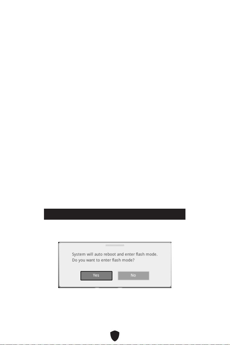
63
Réinitialiser le BIOS
Il se peut que vous ayez besoin de récupérer les réglages BIOS par défaut pour
résoudre des problèmes. Pour réinitialiser les réglages du BIOS, veuillez suivre l’une
des méthodes suivantes :
Allez dans le BIOS et appuyez sur F6 pour charger les réglages par défaut.
Court-circuitez le cavalier Clear CMOS sur la carte mère.
Appuyez sur le bouton Clear CMOS sur le panneau E/S arrière.
Important
Assurez-vous que l’ordinateur est éteint avant d’effacer les données CMOS. Veuillez
vous référer à la section cavalier/bouton Clear CMOS pour en savoir plus sur la
réinitialisation du BIOS.
Mettre le BIOS à jour
Mettre le BIOS à jour avec M-FLASH
Avant la mise à jour :
Veuillez télécharger la dernière version du BIOS compatible à votre carte mère sur le
site MSI. Ensuite, veuillez sauvegarder le profil BIOS sur la clé USB.
Mettre le BIOS à jour :
1. Accédez au BIOS ROM voulu avec le commutateur Multi-BIOS. Ignorez cette étape
si votre carte mère ne possède pas ce commutateur.
2. Insérez la clé USB contenant le fichier de mise à jour au port USB.
3. Veuillez vous référer aux méthodes suivantes pour passer en mode flash.
• Redémarrez et appuyez sur la touche Ctrl + F5 pendant le processus de POST et
cliquez sur Oui pour redémarrer le système.
Press <Ctrl+F5> to activate M-Flash for BIOS update.
• Redémarrez et appuyez sur la touche Del pendant le processus de POST pour
entrer dans le BIOS. Cliquez sur le bouton M-FLASH et cliquez sur Oui pour
redémarrer le système.
4. Choisissez un profil BIOS pour commencer la mise à jour du BIOS.
5. Lorsque vous y êtes invité, cliquez sur Oui pour lancer la restauration du BIOS.
6. Une fois la mise à jour terminée, le système redémarrera automatiquement.

64
Mettre le BIOS à jour avec MSI Center
Avant la mise à jour :
Assurez-vous que le lecteur LAN est bien installé et que l’ordinateur est
correctement connecté à internet.
Veuillez désactiver tous les autres logiciels d’application avant de mettre à jour le
BIOS.
Mettre le BIOS à jour :
1. Installez et lancez MSI Center et accédez à la page Support.
2. Choisissez Live Update et cliquez sur le bouton Avancé.
3. Choisissez le profil BIOS et cliquez sur le bouton Installer.
4. Le rappel d’installation apparaît. Cliquez ensuite sur le bouton Installer.
5. Le système redémarrera automatiquement pour la mise à jour du BIOS.
6. Une fois la mise à jour terminée, le système redémarrera automatiquement.
Mettre le BIOS à jour avec Bouton Flash BIOS
1. Veuillez télécharger la dernière version du BIOS compatible à votre carte mère sur
le site MSI®.
2. Renommez le profil BIOS en MSI.ROM et enregistrez-le à la racine de la clé USB.
3. Connectez l’alimentation aux connecteurs CPU_PWR1 et ATX_PWR1. (Pas besoin
d’installer le processeur et la mémoire.)
4. Branchez la clé USB contenant le fichier MSI.ROM au Port Flash BIOS situé sur le
panneau E/S arrière.
5. Appuyez sur le Bouton Flash BIOS pour flasher le BIOS. Le voyant LED
commencera alors à clignoter.
6. Une fois le processus terminé, la LED s’éteint.

1
........................................................................... 3
.................................................................................. 15
........................................................................................... 20
.................................................................................................... 21
.......................................................................................... 22
....................................................... 24
............................................................................ 24
................................................................................................. 26
............................................................................ 27
........................................................................................... 28
......................................................................................................... 29
................................................................... 30
......................................................................... 31
................................................. 38
....................... 38
............................................................ 39
............................................................ 39
................................................... 40
........................................................... 41
.......................................................... 41
......................... 42
............................................................................. 42
................................................................................ 43
............................................................................... 43
.................... 44
..................................... 45
....................................................................................... 45
..................................................................................... 46
............................ 47
............................................................ 48
......................................................................................... 49
...................................................................................... 49

2
................................................. 49
........................ 49
............................................................................ 50
..................................................................................................... 50
................................................................................. 50
................................................................. 57
........................... 58
MSI Center ............................................................................................................ 60
UEFI BIOS .................................................................................................................... 61
.................................................................................................... 62
........................................................................................................... 63
................................................................................................. 63

3

4
•
•
•
•
•
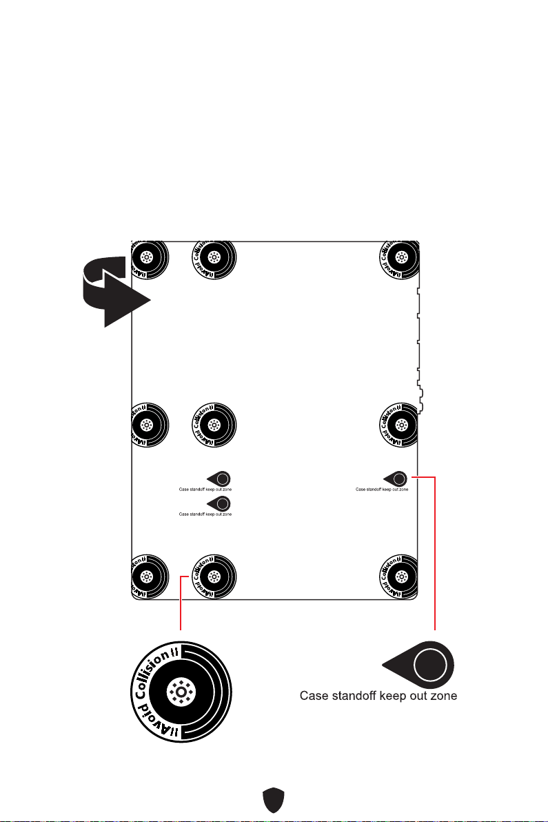
5
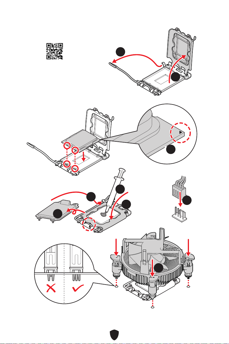
6
https://youtu.be/KMf9oIDsGes
11
22
33
66
44
55
77
88
99

7
DIMMA2 DIMMA2
DIMMB2
DIMMA1
DIMMA2
DIMMB1
DIMMB2
https://youtu.be/XiNmkDNZcZk

8
HDD LED
RESET SW
http://youtu.be/DPELIdVNZUI
JFP1
HDD LED
HDD LED -
HDD LED +
POWER LED -
POWER LED +
POWER LED
RESET SW
POWER SW
POWER LED+
POWER LED-
HDD LED
1
2 10
9
Power LED
Reserved
Power Switch
JFP1
Reset SwitchHDD LED

9
11
https://youtu.be/wWI6Qt51Wnc
22
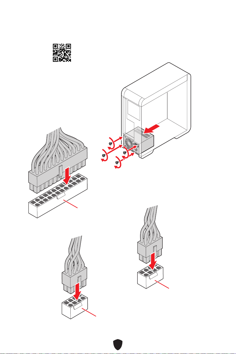
10
http://youtu.be/gkDYyR_83I4
CPU_PWR1
CPU_PWR2
ATX_PWR1

11
http://youtu.be/RZsMpqxythc
11
22
33
44
55

12
http://youtu.be/mG0GZpr9w_A
11
22
33
44
55
66

13

14
44
33
11
22

15
Intel® Z790
•
•
•
•
Channel
•
•
•
•
•
•

16
/
**
•
•
•
•
•
•
•
•
•
•
•
•
•
•
•
•
•
•
RAID
Realtek® ALC4080 Codec

17
LAN
Intel® Wi-Fi 6E
Windows 11.
USB
•
•

18
LED
ASMedia ASM3242)
NUVOTON NCT6687D-M
UEFI AMI BIOS
ACPI 6.4, SMBIOS 3.5

19
MSI Center
Intel Extreme Tuning Utility
MSI APP Player (BlueStacks)
CPU-Z MSI GAMING
Norton 360 Deluxe
AIDA64 Extreme - MSI Edition
Tile

20
MSI Center
• Gaming Mode
• Smart Priority
• Game Highlights
• Mystic Light
• Ambient Link
• Frozr AI Cooling
• User Scenario
• True Color
• Live Update
• Hardware Monitoring
• Super Charger
• Devices Speed Up
• Smart Image Finder
• MSI Companion
• Double-sided M.2 Shield Frozr
• Extended Heatsink Design Heat-pipe
•
•
SYSTEM)
• Core Boost
• VRM Power Design (VCPU / VGT /
AUX)
• Dual CPU Power
• Memory Boost
•
•
•
• Server Grade PCB
• 2oz Copper thickened PCB
• PCI-E Steel Armor
•
• Screwless M.2 Shield Frozr
•
•
•
•
•
• Audio Boost 5
• Mystic Light
• Mystic Light Extension (RGB)
• Mystic Light Extension (A-RAINBOW
V2)
• Ambient Link
BIOS
• Click BIOS 5

21
•
•
•
•
•
•
•
•
•
•
.
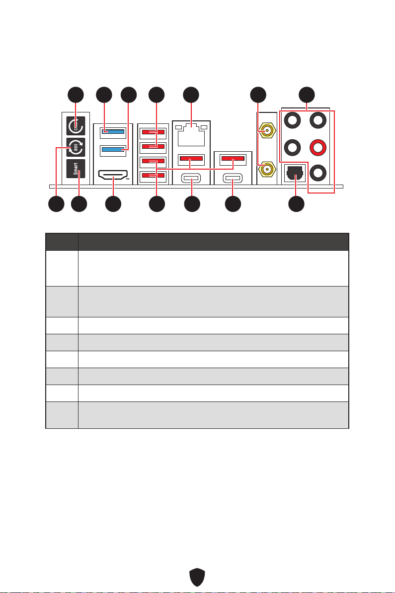
22
1
2
3
4
5
6
7
8
11 77
88 101099 14141313
55 66
12121111
3322 44
23
9
Mystic Light
.
Safe Boot
Turbo Fan
10
11
12
13
14

24
AUDIO INPUT

25
AUDIO INPUT
Rear Front
Center/
Subwoofer
AUDIO INPUT
Rear Front
Center/
Subwoofer
AUDIO INPUT
Rear Front
Side Center/
Subwoofer

26
1.
2.
11
22
3.

27
CPU_FAN1
PUMP_FAN1
SYS_FAN5
SYS_FAN4
JARGB_V2_2
ATX_PWR1
JUSB4
JUSB3
CPU_PWR1
CPU_PWR2
DIMMA2
DIMMB1
DIMMB2
DIMMA1
JCI1
JFP1
JBAT1
JOCFS1
LED_SW1
SYS_FAN3
SYS_FAN2
SYS_FAN1
JDASH1
JPWRLED1
JTBT1
JARGB_V2_1
JRGB1
JAUD1
JUSB2
JUSB1
M2_5
M2_1
M2_2
M2_3
M2_4
PCI_E1
PCI_E2
PCI_E3
JFP2
JTPM1

28

29
DIMMA1 DIMMB1
DIMMA2 DIMMB2
DIMMA2.
DRAM Frequency
DIMMA2 DIMMA2
DIMMB2
DIMMA1
DIMMA2
DIMMB1
DIMMB2

30
PCI_E1
PCI_E2
PCI_E3
MSI Graphics Card Bolster
PCI_E1.
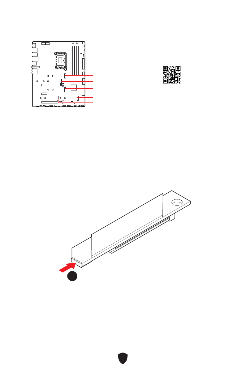
31
M2_1
M2_2
M2_4
M2_5
M2_3
1.
Shield Frozr.
11
https://youtu.be/J88vcXeLido
Screwless M.2 Shield Frozr.

32
2.
22
3.
33
4.
44
2260 SSD

33
5.
6.
30º30º
30º30º
2280 SSD
2260 SSD
66
66
55
55
7.
Shield Frozr.
8.
9.
99
88
77

34
1.
11
11
2.
22
3.
33
33
22110 SSD
2260 SSD
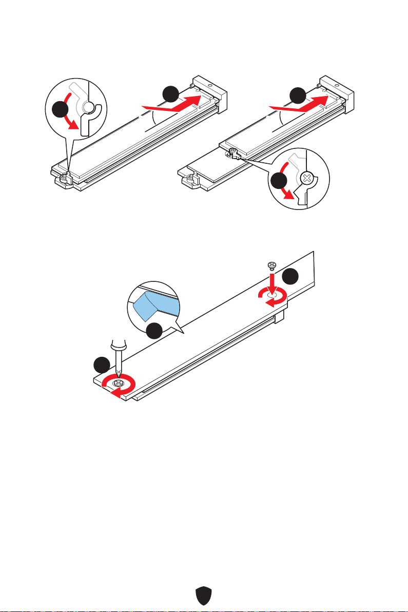
35
4.
5.
30º30º
30º30º
22110 SSD
2280 SSD
2260 SSD
44
44
55
55
6.
7.
66
77
77

36
1.
11
11
11
11
2.
22
3.
33
2260 SSD

37
4.
5.
30º30º
30º30º
2280 SSD
2260 SSD
55
44
44
55
6.
7.
66
77
77 77
77
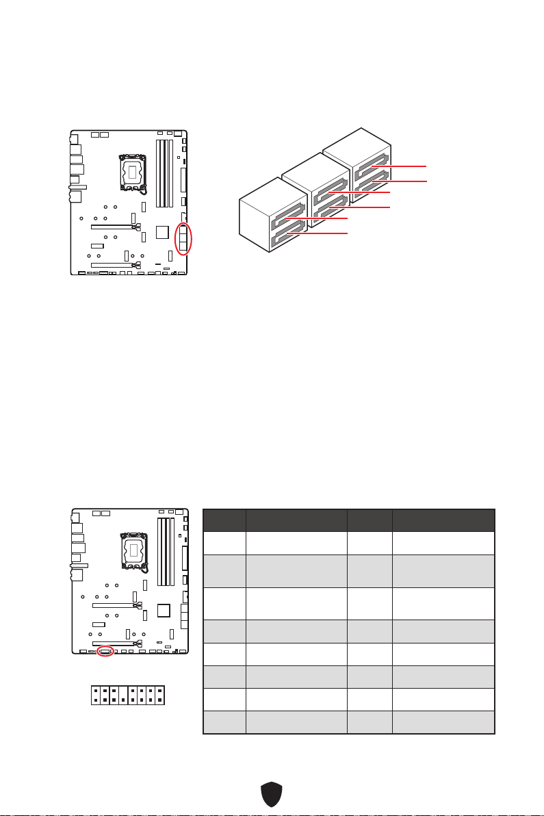
38
SATA5
SATA7
SATA_A1
SATA6
SATA8
SATA_A2
Thunderbolt
Thunderbolt.
1
2 16
15
1 TBT_FORCE_PWR 2 TBT_S0IX_ENTRY_REQ
3
TBT_CIO_PLUG_
EVENT#
4 TBT_S0IX_ENTRY_ACK
5 SLP_S3#_TBT 6
TBT_PSON_
OVERRIDE_N
7 SLP_S5#_TBT 8 No Pin
9 Ground 10 SMBCLK_VSB
11 DG_PEWAKE# 12 SMBDATA_VSB
13 TBT_RTD3_PWR_EN 14 Ground
15 TBT_CARD_DET_R# 16 PD_IRQ#
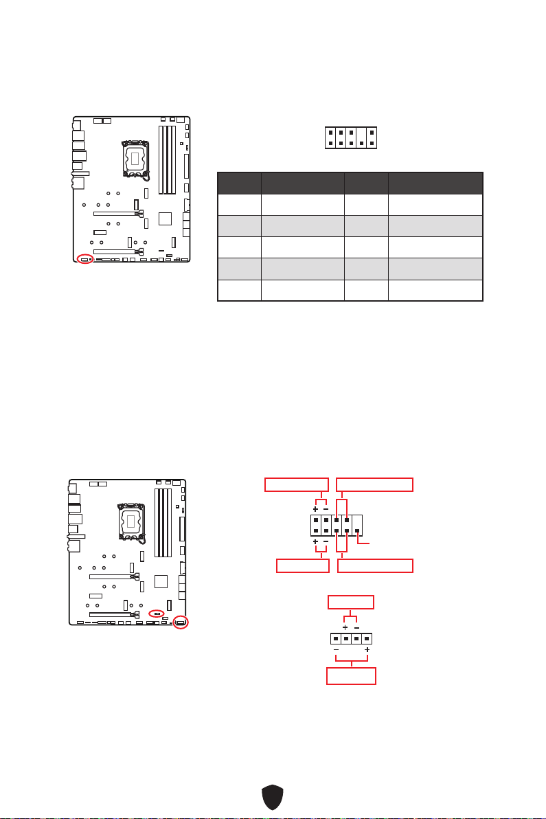
39
1
2 10
9
1 MIC L 2 Ground
3 MIC R 4 NC
5 Head Phone R 6 MIC Detection
7 SENSE_SEND 8 No Pin
9 Head Phone L 10 Head Phone Detection
1
2 10
9
Power LED
Reserved
Power Switch
JFP1
Reset SwitchHDD LED
1
JFP2
Buzzer
Speaker
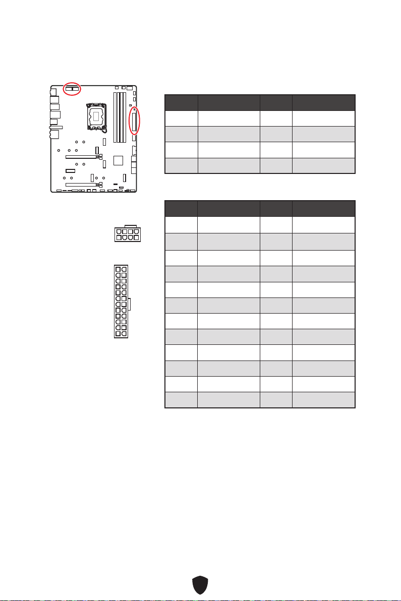
40
CPU_PWR1~2
1 Ground 2 Ground
3 Ground 4 Ground
5 +12V 6 +12V
7 +12V 8 +12V
ATX_PWR1
1 +3.3V 2 +3.3V
3 Ground 4 +5V
5 Ground 6 +5V
7 Ground 8 PWR OK
9 5VSB 10 +12V
11 +12V 12 +3.3V
13 +3.3V 14 -12V
15 Ground 16 PS-ON#
17 Ground 18 Ground
19 Ground 20 Res
21 +5V 22 +5V
23 +5V 24 Ground
5
4 1
8
CPU_PWR1~2
24
131
12
ATX_PWR1

41
1. JCI1.
2.
3. BIOS > SETTINGS > Security > Chassis Intrusion Configuration.
4. Chassis IntrusionEnabled.
5. F10
EnterYes.
6.
1. BIOS > SETTINGS > Security > Chassis Intrusion Configuration.
2. Chassis Intrusion, Reset.
3. F10
EnterYes.
1 No Pin 2 NC
3
MCU_SMB_SCL_M
4 MCU_SMB_SDA_M
5 VCC5 6 Ground
1
2
5
6
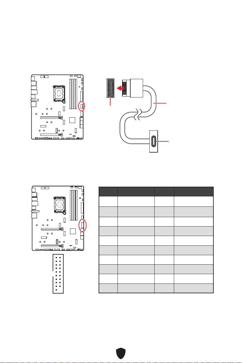
42
JUSB4
1 Power 2 USB3_RX_DN
3 USB3_RX_DP 4 Ground
5 USB3_TX_C_DN 6 USB3_TX_C_DP
7 Ground 8 USB2.0-
9 USB2.0+ 10 Ground
11 USB2.0+ 12 USB2.0-
13 Ground 14 USB3_TX_C_DP
15 USB3_TX_C_DN 16 Ground
17 USB3_RX_DP 18 USB3_RX_DN
19 Power 20 No Pin
1
10 11
20
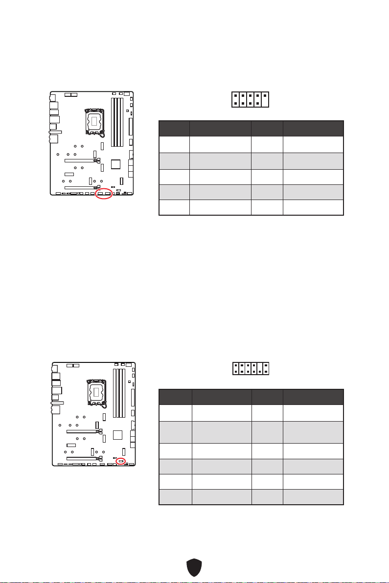
43
1 VCC 2 VCC
3 USB0- 4 USB1-
5 USB0+ 6 USB1+
7 Ground 8 Ground
9 No Pin 10 NC
1
2 10
9
1 SPI Power 2 SPI Chip Select
3
Master In Slave Out
(SPI Data)
4
Master Out Slave In
(SPI Data)
5 Reserved 6 SPI Clock
7 Ground 8 SPI Reset
9 Reserved 10 No Pin
11 Reserved 12 Interrupt Request
1
2 12
11
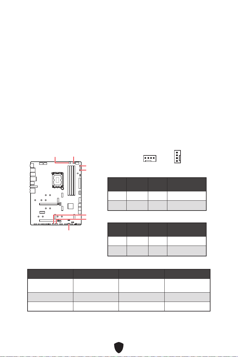
44
BIOS > HARDWARE MONITOR
Smart
Fan Mode
CPU_FAN1
SYS_FAN2
SYS_FAN1
SYS_FAN3
PUMP_FAN1
SYS_FAN5
SYS_FAN4
1 Ground 2 +12V
3 Sense 4 Speed Control Signal
1 Ground 2 Voltage Control
3 Sense 4 NC
CPU_FAN1
2A
PUMP_FAN1
SYS_FAN1~5
1
1

45
1.
2. JBAT1
3. JBAT1.
4.
1.
2.

46
1
G
R
B
JRGB
1
1
G
R
B
1 +12V 2 G
3 R 4 B
1

47
1 +5V 2 Data
3 No Pin 4 Ground
1
1
1
1
1
D
+5V
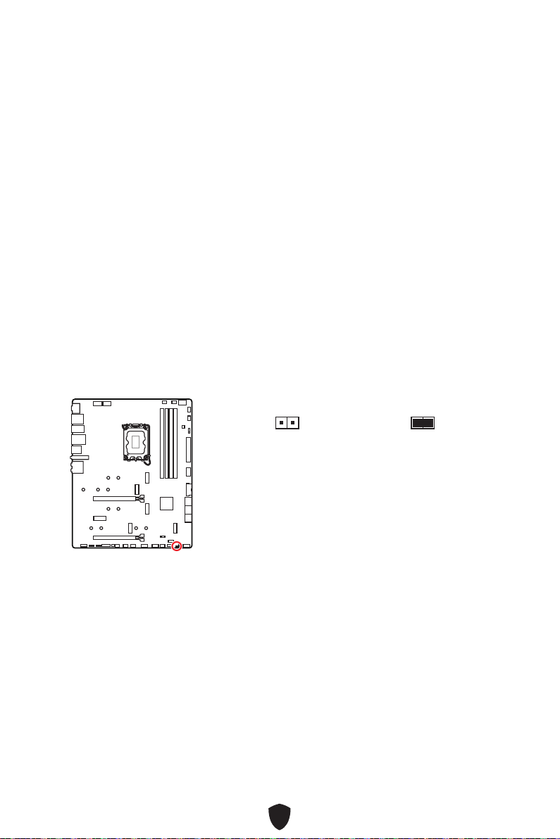
48
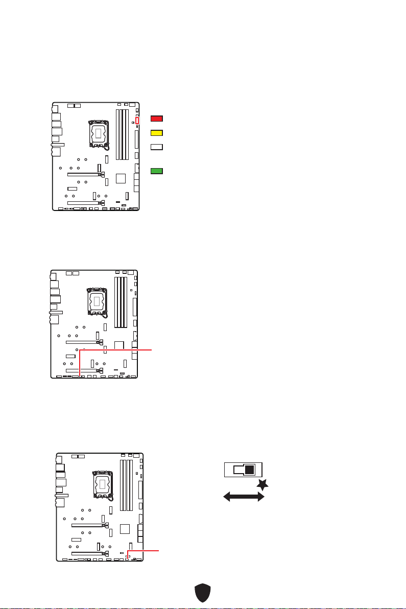
49
CPU
DRAM
VGA
BOOT
LED_SW1
LED_OFF
LED_ON
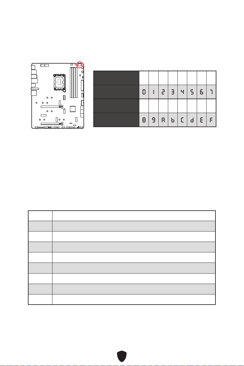
50
Security (SEC)
Pre-EFI Initialization (PEI)
Driver Execution Environment (DXE)
Boot Device Selection (BDS)
01
02
03
04
06
07
08
09
0B
0 1 2 3 4 5 6 7
8 9 A B C D E F
51
0C - 0D
SEC
0E
0F
10
11
12 - 14
15
16 - 18
System Agent)
19
1A - 1C
2B
2C
2D
2E
2F
31
32
33
34
Processor(s) (AP)
35
36
Management Mode (SMM)
37
Agent
38 - 3A
52
3B
3C - 3E
4F
50
51
52
53
54
55
56
57
58
59
5A
5B
5C - 5F
60
61
62
63
64 - 67
68
69
6A

53
6B - 6F
70
71
72
73 - 77
78
79
7A - 7F
90
(BDS)
91
92
93
94 PCI Bus Enumeration 32
95 PCI Bus Request Resources
96 PCI Bus Assign Resources
97
98
99
9A
9B USB Reset
9C USB Detect
9D USB Enable
9E - 9F
A0
A1 IDE Reset
A2 IDE Detect
A3 IDE Enable
A4
A5 SCSI Reset
54
A6 SCSI Detect
A7 SCSI Enable
A8
A9
AB
AD
AE
AF
B0
B1
B2
B3 System Reset
B4 USB hot plug
B5 PCI bus hot plug
B6
B7
B8 - BF
D0
D1
D2
D3
D4
D5
D6
D7
D8
D9
DA
55
DB
DC
E0
E1
E2
E3 OS S3 wake vector call
E4 - E7
E8
E9
EA
EB
EC - EF
F0
F1
F2
F3
F4
F5 - F7
F8
F9
FA
FB - FF
56
01
02
03
04
05
10
20
30
40
AC
PIC.
AA
APIC.
00 - 99

57
1.
2.
3. Restart
4. F11
5.
6. Press any key
to boot from CD or DVD...
7.

58
Installer
1.
2.
3.
4.

59
5.
6.
60
1.
2.
3.
4. DVDSetup.
5.
Drivers/Software.
6. Install
7.
8. OK
9.
MSI Center
http://download.msi.com/manual/mb/MSICENTER.pdf

61
UEFI BIOS
UEFI
There is no GOP
(Graphics Output protocol) support detected in this graphics card
1.
2. DeletePress DEL
key to enter Setup Menu, F11 to enter Boot Menu
3.
UEFI

62
HELP.
DeletePress DEL key to
enter Setup Menu, F11 to enter Boot Menu
F1:
F2:
F3:
F4:
F5:
F6:
F7:
F8:
F9:
F10:
F12:
Ctrl+F:
https://download.msi.com/archive/mnu_exe/mb/Intel700BIOSru.pdf

63
F6
1.
2.
3.
• Ctrl+F5
Yes
Press <Ctrl+F5> to activate M-Flash for BIOS update.
• Del
M-FLASH
4.
5. Yes
6.

64
1. Support.
2. Live UpdateAdvance.
3. Install.
4. Install.
5.
6.
1.
2.
3. CPU_PWR1ATX_PWR1
4.
5. Flash BIOS
6.

1
............................................................................................................ 3
.............................................................................................................................. 15
........................................................................................................... 20
....................................................................................................... 21
.............................................................................................. 22
........................................................................................... 24
...................................................................................... 24
............................................................................................... 26
................................................................................................ 27
........................................................................................................... 28
........................................................................................................ 29
................................................................................. 30
................................................................................ 31
................................................ 38
........................................................... 38
................................................................... 39
................................................................. 39
......................................................... 40
..................................................................... 41
................................................. 41
.................................. 42
......................................................................... 42
............................................................................... 43
........................................................................ 43
................................. 44
..................................................... 45
........................................................................................ 45
................................................................................. 46
........................... 47
.............................................................................. 48
............................................................................................................ 49
EZ Debug LED ....................................................................................................... 49

2
.................................................................................... 49
............................................................................ 49
................................................................................................ 50
........................................................................................................ 50
..................................................................................... 50
......................................................57
..................................... 58
MSI Center ............................................................................................................ 60
UEFI BIOS .................................................................................................................... 61
........................................................................................................... 62
...................................................................................................... 63
........................................................................................ 63

3
Intel® LGA1700 CPU

4
•
•
•
•
•

5

6
https://youtu.be/KMf9oIDsGes
11
22
33
66
44
55
77
88
99
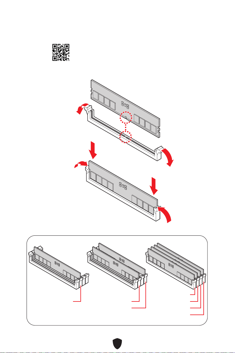
7
DIMMA2 DIMMA2
DIMMB2
DIMMA1
DIMMA2
DIMMB1
DIMMB2
https://youtu.be/XiNmkDNZcZk

8
HDD LED
RESET SW
http://youtu.be/DPELIdVNZUI
JFP1
HDD LED
HDD LED -
HDD LED +
POWER LED -
POWER LED +
POWER LED
RESET SW
POWER SW
POWER LED+
POWER LED-
HDD LED
1
2 10
9
Power LED
Reserved
Power Switch
JFP1
Reset SwitchHDD LED

9
11
https://youtu.be/wWI6Qt51Wnc
3 kgf·cm*
*3 kgf·cm
= 0.3 N·m
= 2.6 lbf·in
22

10
http://youtu.be/gkDYyR_83I4
CPU_PWR1
CPU_PWR2
ATX_PWR1

11
http://youtu.be/RZsMpqxythc
11
22
33
44
55

12
http://youtu.be/mG0GZpr9w_A
11
22
33
44
55
66

13

14
44
33
11
22

15
CPU
•
•
•
•
•
•
•
•
•
•
/
**
•
•

16
•
•
•
•
•
•
•
•
•
•
•
•
•
•
•
•
RAID
LAN
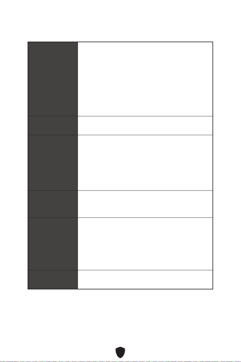
17
Wi-Fi & Bluetooth®
Intel® Wi-Fi 6E
•
•

18
2-Digit Debug Code LED x1
EZ Debug LED x4
12 in. x 9.6 in. (30.5 cm x 24.4 cm)
UEFI AMI BIOS
ACPI 6.4, SMBIOS 3.5

19
MSI Center
Intel Extreme Tuning Utility
MSI APP Player (BlueStacks)
CPU-Z MSI GAMING
Norton 360 Deluxe
AIDA64 Extreme - MSI Edition
Tile

20
MSI Center
• Gaming Mode
• Smart Priority
• Game Highlights
• Mystic Light
• Ambient Link
• Frozr AI Cooling
• User Scenario
• True Color
• Live Update
• Hardware Monitoring
• Super Charger
• Devices Speed Up
• Smart Image Finder
• MSI Companion
• Double-sided M.2 Shield Frozr
•
•
•
SYSTEM)
• Core Boost
•
•
• Memory Boost
•
•
•
•
•
• PCI-E Steel Armor
•
• Screwless M.2 Shield Frozr
•
• EZ DEBUG LED
•
•
•
• Audio Boost 5
• Mystic Light
•
•
• Ambient Link
BIOS
• Click BIOS 5

21
•
•
•
•
•
•
•
•
•
•

22
1
2
3
4
5
6
7
8
11 77
88 101099 14141313
55 66
12121111
3322 44
23
9
10
11
12
13
14
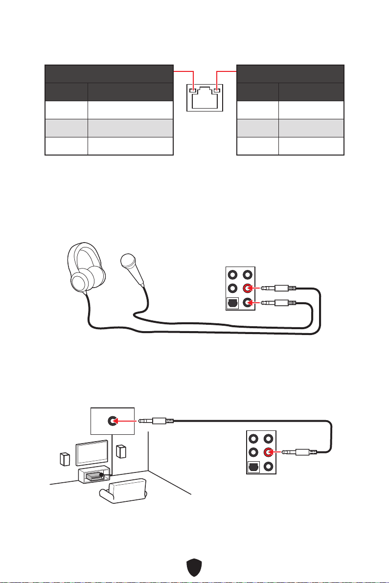
24
Off
Off 10 Mbps
100/1000 Mbps
2.5 Gbps
AUDIO INPUT

25
AUDIO INPUT
Rear Front
Center/
Subwoofer
AUDIO INPUT
Rear Front
Center/
Subwoofer
AUDIO INPUT
Rear Front
Side Center/
Subwoofer
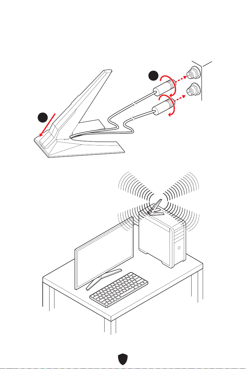
26
1.
2.
11
22
3.
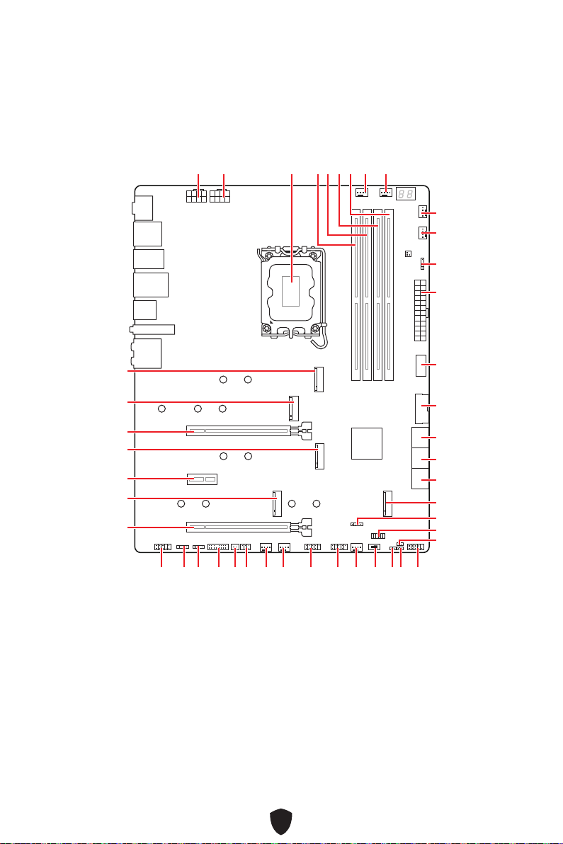
27
CPU_FAN1
PUMP_FAN1
SYS_FAN5
SYS_FAN4
JARGB_V2_2
ATX_PWR1
JUSB4
JUSB3
CPU_PWR1
CPU_PWR2
DIMMA2
DIMMB1
DIMMB2
DIMMA1
JCI1
JFP1
JBAT1
JOCFS1
LED_SW1
SYS_FAN3
SYS_FAN2
SYS_FAN1
JDASH1
JPWRLED1
JTBT1
JARGB_V2_1
JRGB1
JAUD1
JUSB2
JUSB1
M2_5
M2_1
M2_2
M2_3
M2_4
PCI_E1
PCI_E2
PCI_E3
JFP2
JTPM1

28
4
50.85 mm

29
DIMMA1 DIMMB1
DIMMA2 DIMMB2
DIMMA2
DRAM Frequency
DIMMA2 DIMMA2
DIMMB2
DIMMA1
DIMMA2
DIMMB1
DIMMB2

30
PCI_E1
PCI_E2
PCI_E3
MSI Graphics Card Bolster
PCI_E1

31
M2_1
M2_2
M2_4
M2_5
M2_3
1.
11
https://youtu.be/J88vcXeLido
Screwless M.2 Shield Frozr
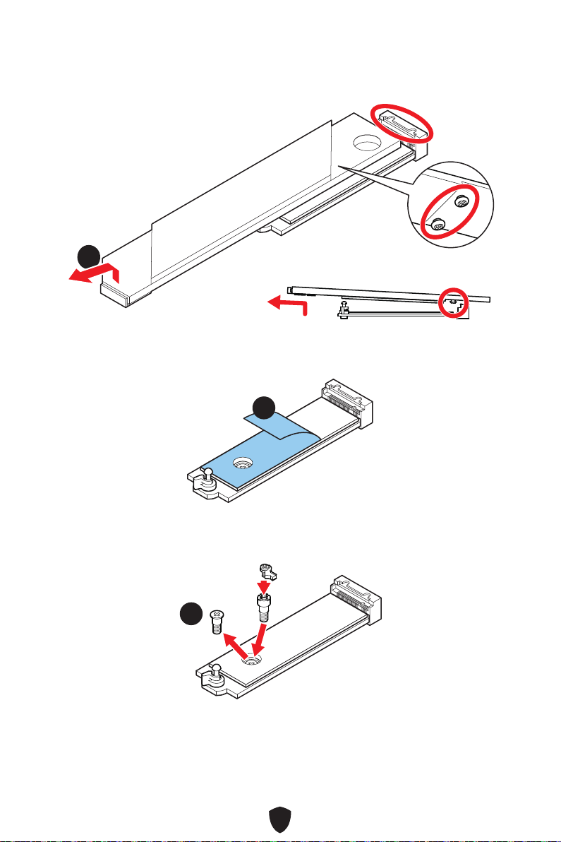
32
2.
22
3.
33
4.
44
2260 SSD
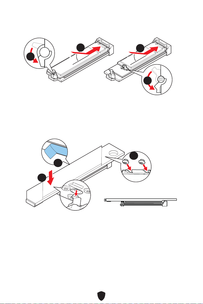
33
5.
6.
30º30º
30º30º
2280 SSD
2260 SSD
66
66
55
55
7.
8.
9.
99
88
77

34
1.
11
11
2.
22
3.
33
33
22110 SSD
2260 SSD

35
4.
5.
30º30º
30º30º
22110 SSD
2280 SSD
2260 SSD
44
44
55
55
6.
7.
66
77
77
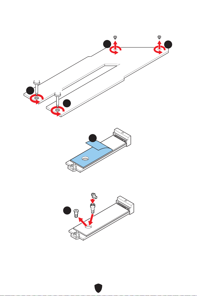
36
1.
11
11
11
11
2.
22
3.
33
2260 SSD
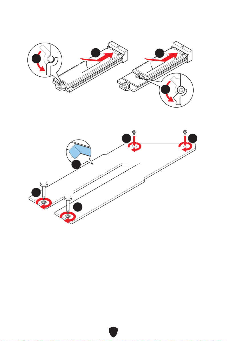
37
4.
5.
30º30º
30º30º
2280 SSD
2260 SSD
55
44
44
55
6.
7.
66
77
77 77
77

38
SATA5
SATA7
SATA_A1
SATA6
SATA8
SATA_A2
1
2 16
15
1 TBT_FORCE_PWR 2 TBT_S0IX_ENTRY_REQ
3
TBT_CIO_PLUG_
EVENT#
4 TBT_S0IX_ENTRY_ACK
5 SLP_S3#_TBT 6
TBT_PSON_
OVERRIDE_N
7 SLP_S5#_TBT 8 No Pin
9 Ground 10 SMBCLK_VSB
11 DG_PEWAKE# 12 SMBDATA_VSB
13 TBT_RTD3_PWR_EN 14 Ground
15 TBT_CARD_DET_R# 16 PD_IRQ#

39
1
2 10
9
1 MIC L 2 Ground
3 MIC R 4 NC
5 Head Phone R 6 MIC Detection
7 SENSE_SEND 8 No Pin
9 Head Phone L 10 Head Phone Detection
1
2 10
9
Power LED
Reserved
Power Switch
JFP1
Reset SwitchHDD LED
1
JFP2
Buzzer
Speaker

40
CPU_PWR1~2
1 Ground 2 Ground
3 Ground 4 Ground
5 +12V 6 +12V
7 +12V 8 +12V
ATX_PWR1
1 +3.3V 2 +3.3V
3 Ground 4 +5V
5 Ground 6 +5V
7 Ground 8 PWR OK
9 5VSB 10 +12V
11 +12V 12 +3.3V
13 +3.3V 14 -12V
15 Ground 16 PS-ON#
17 Ground 18 Ground
19 Ground 20 Res
21 +5V 22 +5V
23 +5V 24 Ground
5
4 1
8
CPU_PWR1~2
24
131
12
ATX_PWR1
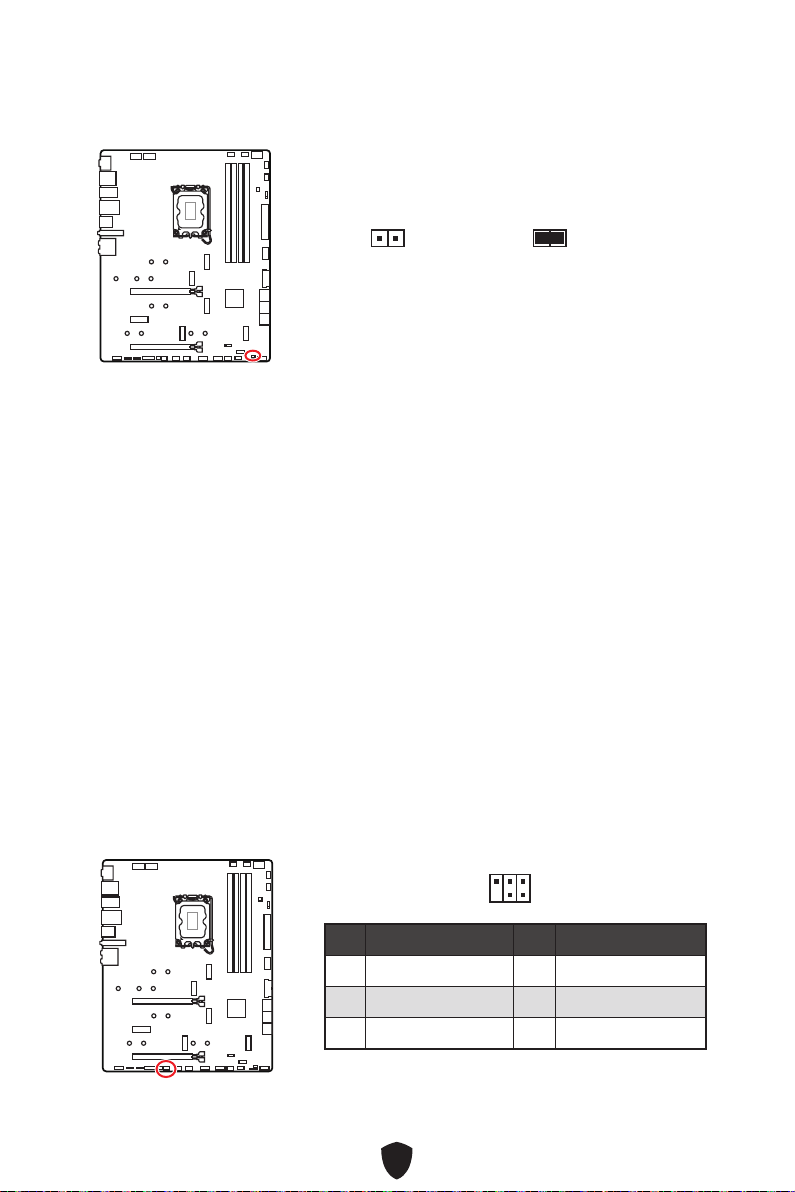
41
1. JCI1
2.
3. BIOS > SETTINGS > Security > Chassis Intrusion Configuration
4. Chassis IntrusionEnabled
5. F10Enter
Yes
6.
1. BIOS > SETTINGS > Security > Chassis Intrusion Configuration
2. Chassis IntrusionReset
3. F10
Yes
1 No Pin 2 NC
3
MCU_SMB_SCL_M
4 MCU_SMB_SDA_M
5 VCC5 6 Ground
1
2
5
6
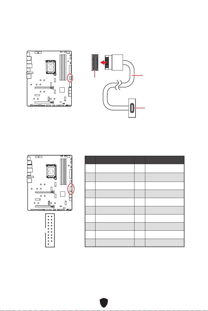
42
JUSB4
1 Power 2 USB3_RX_DN
3 USB3_RX_DP 4 Ground
5 USB3_TX_C_DN 6 USB3_TX_C_DP
7 Ground 8 USB2.0-
9 USB2.0+ 10 Ground
11 USB2.0+ 12 USB2.0-
13 Ground 14 USB3_TX_C_DP
15 USB3_TX_C_DN 16 Ground
17 USB3_RX_DP 18 USB3_RX_DN
19 Power 20 No Pin
1
10 11
20

43
1 VCC 2 VCC
3 USB0- 4 USB1-
5 USB0+ 6 USB1+
7 Ground 8 Ground
9 No Pin 10 NC
1
2 10
9
1 SPI Power 2 SPI Chip Select
3
Master In Slave Out
(SPI Data)
4
Master Out Slave In
(SPI Data)
5 Reserved 6 SPI Clock
7 Ground 8 SPI Reset
9 Reserved 10 No Pin
11 Reserved 12 Interrupt Request
1
2 12
11
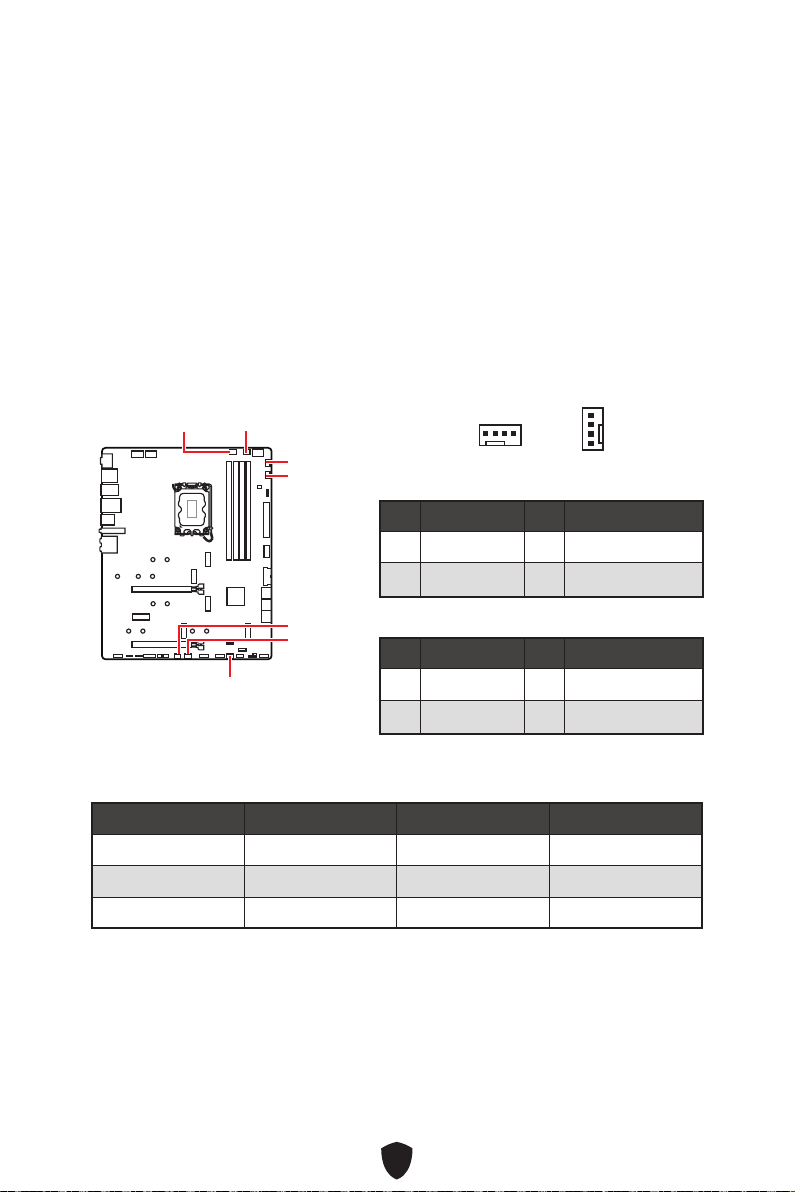
44
BIOS> HARDWARE MONITOR
CPU_FAN1
SYS_FAN2
SYS_FAN1
SYS_FAN3
PUMP_FAN1
SYS_FAN5
SYS_FAN4
1 Ground 2 +12V
3 Sense 4 Speed Control Signal
1 Ground 2 Voltage Control
3 Sense 4 NC
CPU_FAN1 2A 24W
PUMP_FAN1 3A 36W
SYS_FAN1~5 1A 12W
1
1
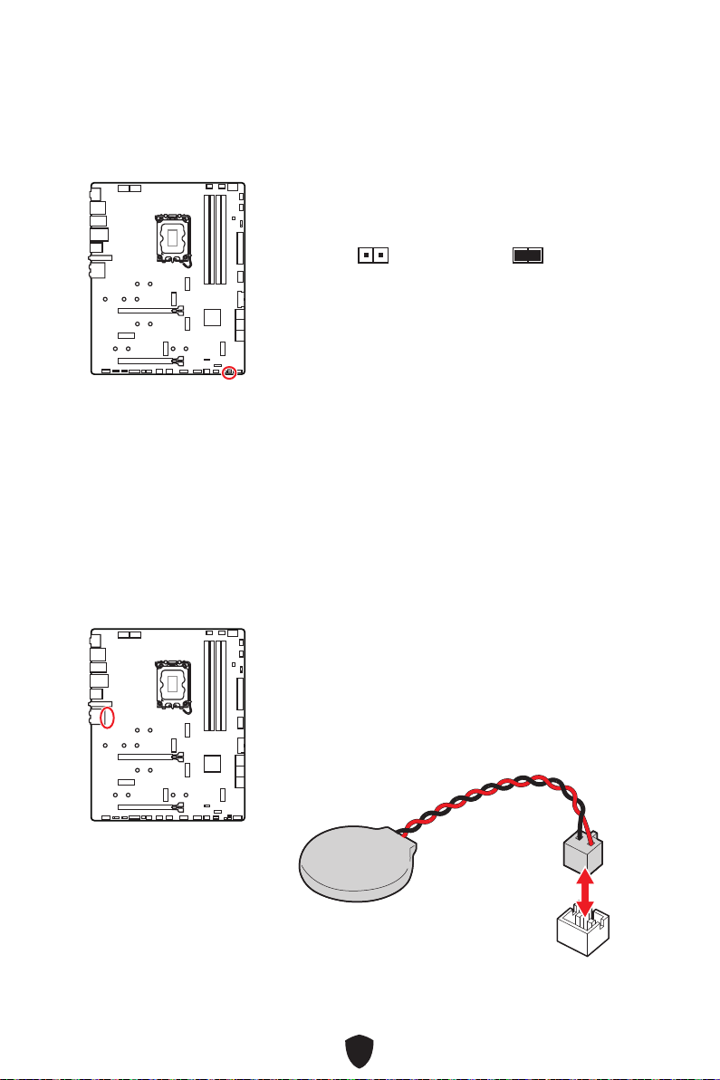
45
1.
2. JBAT1
3. JBAT1
4.
1.
2.

46
1
G
R
B
1
1
G
R
B
1 +12V 2 G
3 R 4 B
1

47
1 +5V 2 Data
3 No Pin 4 Ground
1
1
1
1
1
D
+5V
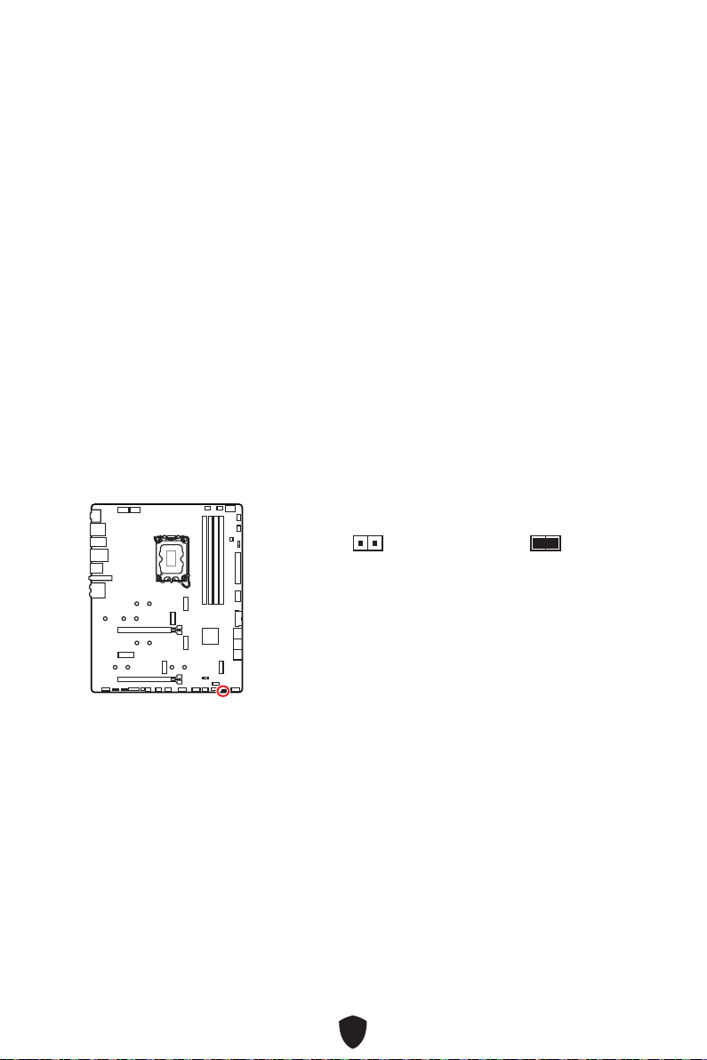
48
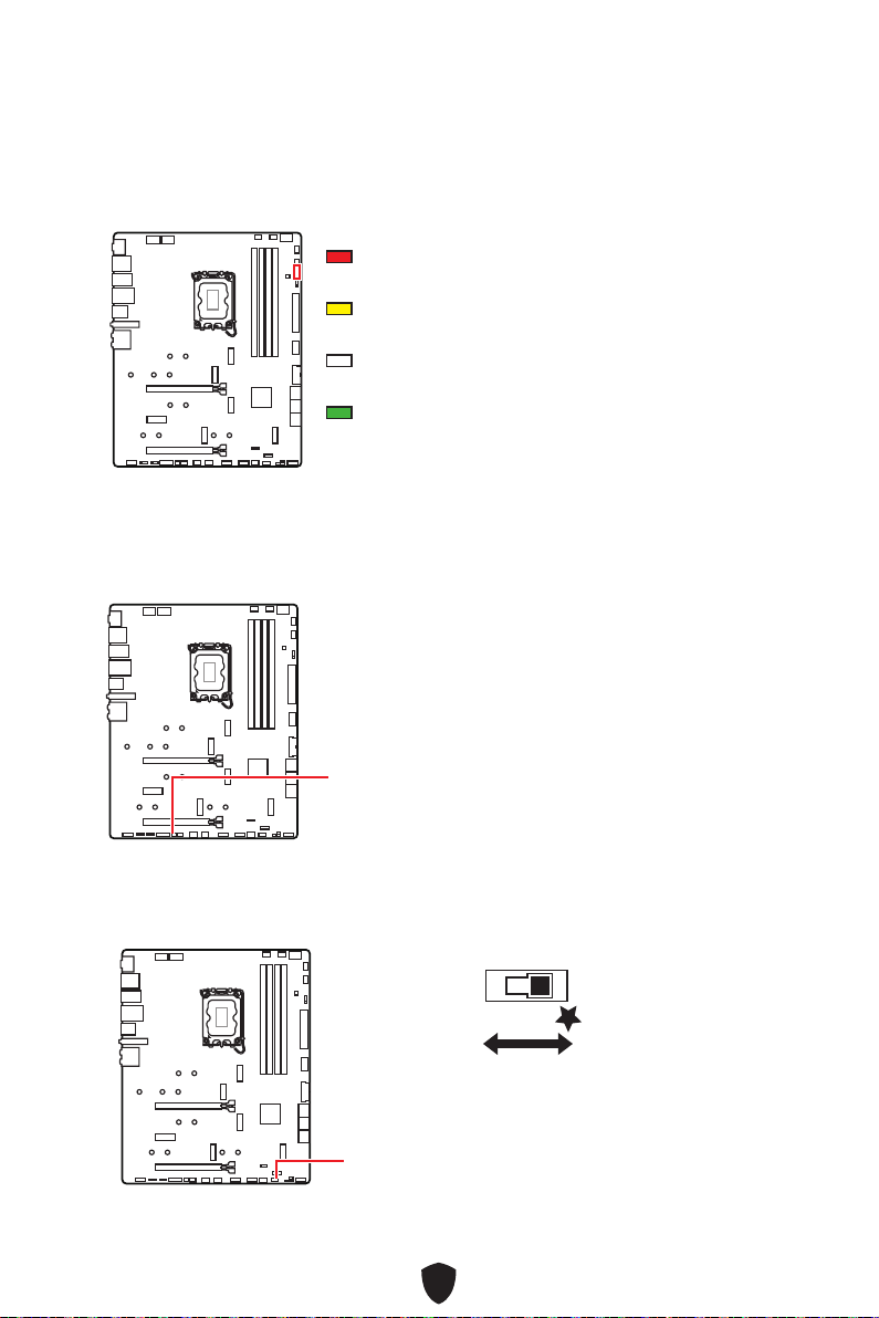
49
EZ Debug LED
CPU
DRAM
VGA
BOOT
LED_SW1
LED_OFF
LED_ON

50
Security (SEC)
Pre-EFI Initialization (PEI)
Driver Execution Environment (DXE)
Boot Device Selection (BDS)
01
02
03
04
06
07
08
09
0B
0C - 0D
0E
0F
0 1 2 3 4 5 6 7
8 9 A B C D E F
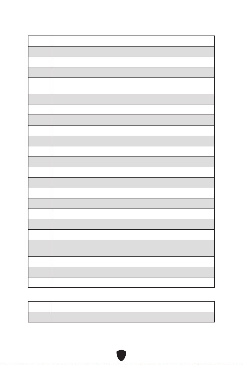
51
10
11
12 - 14
15
16 - 18
19
1A - 1C
2B
2C
2D
2E
2F
31
32
33
34
35
36
37
38 - 3A
3B
3C - 3E
4F
50
51
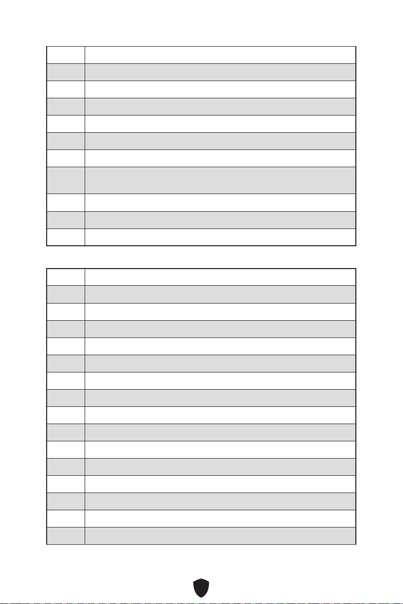
52
52
53
54
55
56
57
58
59
5A
5B
5C - 5F
60
61
62
63
64 - 67
68
69
6A
6B - 6F
70
71
72
73 - 77
78
79
7A - 7F

53
90
91
92
93
94
95
96
97
98
99
9A
9B
9C
9D
9E -9F
A0
A1
A2
A3
A4
A5
A6
A7
A8
A9
AB
AD
AE
AF

54
B0
B1
B2
B3
B4
B5
B6
B7
B8 - BF
D0
D1
D2
D3
D4
D5
D6
D7
D8
D9
DA
DB
DC
E0
E1
E2
E3

55
E4 - E7
E8
E9
EA
EB
EC - EF
F0
F1
F2
F3
F4
F5 - F7
F8
F9
FA
FB - FF
01
02
03
04
05
10
20

56
30
40
AC
AA
00 - 99

57
1.
2.
3. Restart
4. F11
5.
6. Press any key to boot from CD or DVD...
7.
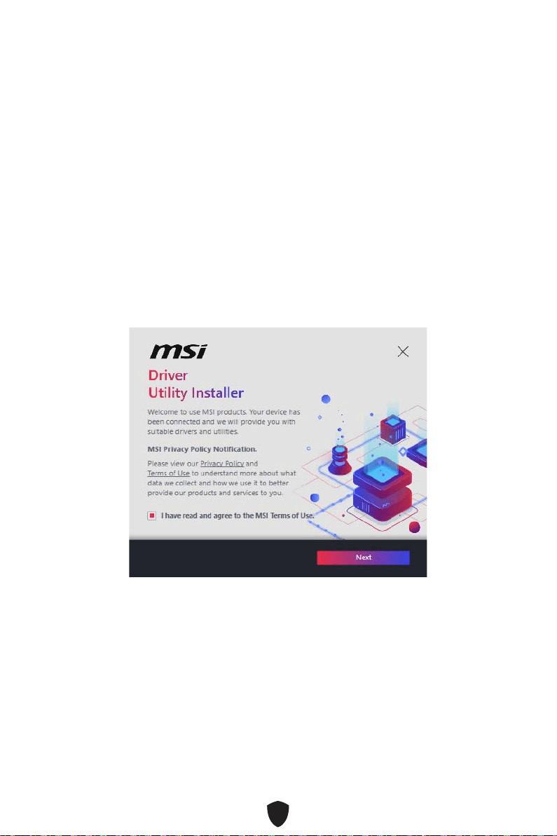
58
1.
2.
3.
4.

59
5.
6.
60
1.
2.
3. Disc Image file
4. DVDSetup
5.
6. Install
7.
8. OK
9.
MSI Center
http://download.msi.com/manual/mb/MSICENTER.pdf

61
UEFI BIOS
1.
2. Press DEL key to enter Setup Menu, F11 to enter Boot Menu
Delete
3.
BIOS Mode: UEFI

62
HELP
Press DEL key to enter Setup Menu, F11 to enter Boot Menu
Delete
F1
F2
F3
F4
F5
F6
F7
F8
F9
F10
F12:
Ctrl+F:
https://download.msi.com/archive/mnu_exe/mb/Intel700BIOSjp.pdf
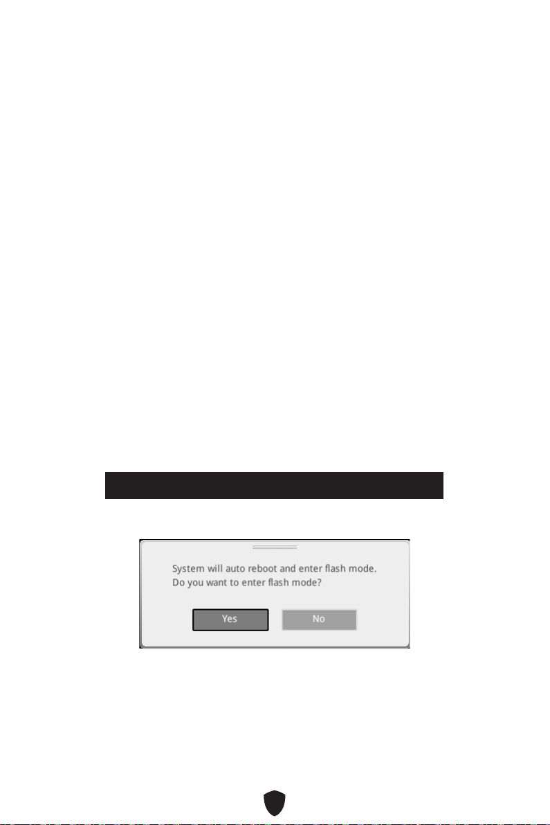
63
F6
1.
2.
3.
• Ctrl + F5
Press <Ctrl+F5> to activate M-Flash for BIOS update.
• DeleteM-FLASH
4.
5. Yes
6.

64
1. Support
2. Live UpdateAdvanced
3. Install
4.
5.
6.
1.
2.
3. CPU_PWR1ATX_PWR1
4.
5.
6.

1
..........................................................................................................3
...................................................................................................................15
...........................................................................................................20
........................................................................................................21
................................................................................................22
........................................................................................ 24
........................................................................................................ 24
...................................................................................................... 26
........................................................................................................27
............................................................................................................... 28
............................................................................................................. 29
..................................................................................... 30
..................................................................................... 31
...................................................... 38
.......................................................................... 38
.................................................................................... 39
................................................................................ 39
............................................................... 40
........................................................................................... 41
............................................................................... 41
.............................................. 42
............................................................................... 42
..................................................................................... 43
....................................................................................... 43
............................................. 44
............................................................... 45
.............................................................................................. 45
....................................................................................... 46
................................. 47
......................................................................................... 48
........................................................................................................49
....................................................................................................... 49

2
................................................................................... 49
..................................................................................... 49
..................................................................................................... 50
............................................................................................................ 50
............................................................................................... 50
................................................................57
................................................... 58
MSI Center ............................................................................................................ 60
UEFI BIOS .........................................................................................................61
.............................................................................................. 62
............................................................................................................... 63
........................................................................................................ 63

3
LGA1700 CPU Fan

4
•
•
•
•
•

5

6
https://youtu.be/KMf9oIDsGes
11
22
33
66
44
55
77
88
99

7
DIMMA2 DIMMA2
DIMMB2
DIMMA1
DIMMA2
DIMMB1
DIMMB2
https://youtu.be/XiNmkDNZcZk

8
HDD LED
RESET SW
http://youtu.be/DPELIdVNZUI
JFP1
HDD LED
HDD LED -
HDD LED +
POWER LED -
POWER LED +
POWER LED
RESET SW
POWER SW
POWER LED+
POWER LED-
HDD LED
1
2 10
9
Reserved
JFP1
HDD LED

9
11
https://youtu.be/wWI6Qt51Wnc
3 kgf·cm*
*3 kgf·cm
= 0.3 N·m
= 2.6 lbf·in
22

10
http://youtu.be/gkDYyR_83I4
CPU_PWR1
CPU_PWR2
ATX_PWR1

11
http://youtu.be/RZsMpqxythc
11
22
33
44
55

12
http://youtu.be/mG0GZpr9w_A
11
22
33
44
55
66

13
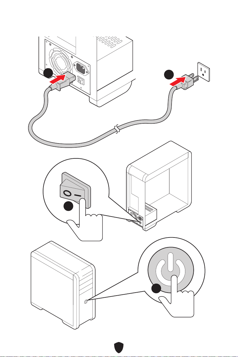
14
44
33
11
22

15
CPU
•
•
•
•
•
•
•
•
•
•
•
• SATA_A1~A2 (ASM1061)

16
•
•
•
•
•
•
•
•
•
•
•
•
•
•
•
•
RAID
LAN

17
•
•

18
Hub)
ASM3242)
12 in. x 9.6 in. (30.5 cm x 24.4 cm)
1x 256 Mb flash
UEFI AMI BIOS
ACPI 6.4, SMBIOS 3.5

19
MSI Center
Norton 360 Deluxe

20
MSI Center
•
•
•
•
• Ambient Link
•
•
• True Color
•
•
•
•
•
•
•
•
•
•
•
•
•
•
•
•
•
•
• 2oz Copper thickened PCB
•
•
•
•
•
•
•
•
•
•
•
•
V2)
• Ambient Link Support
BIOS
•

21
•
•
•
•
•
•
•
•
•
•
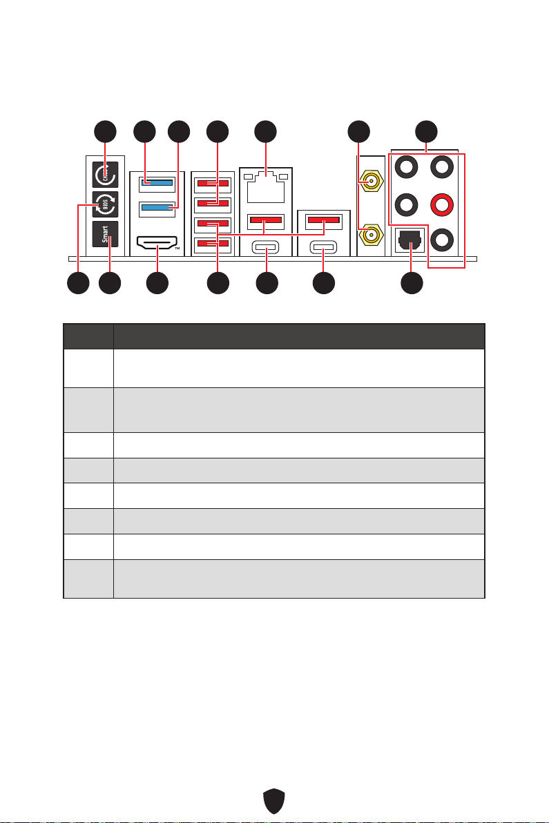
22
1
2
3
4
5
6
7
8
11 77
88 101099 14141313
55 66
12121111
3322 44

23
9
10
11
12
13
14
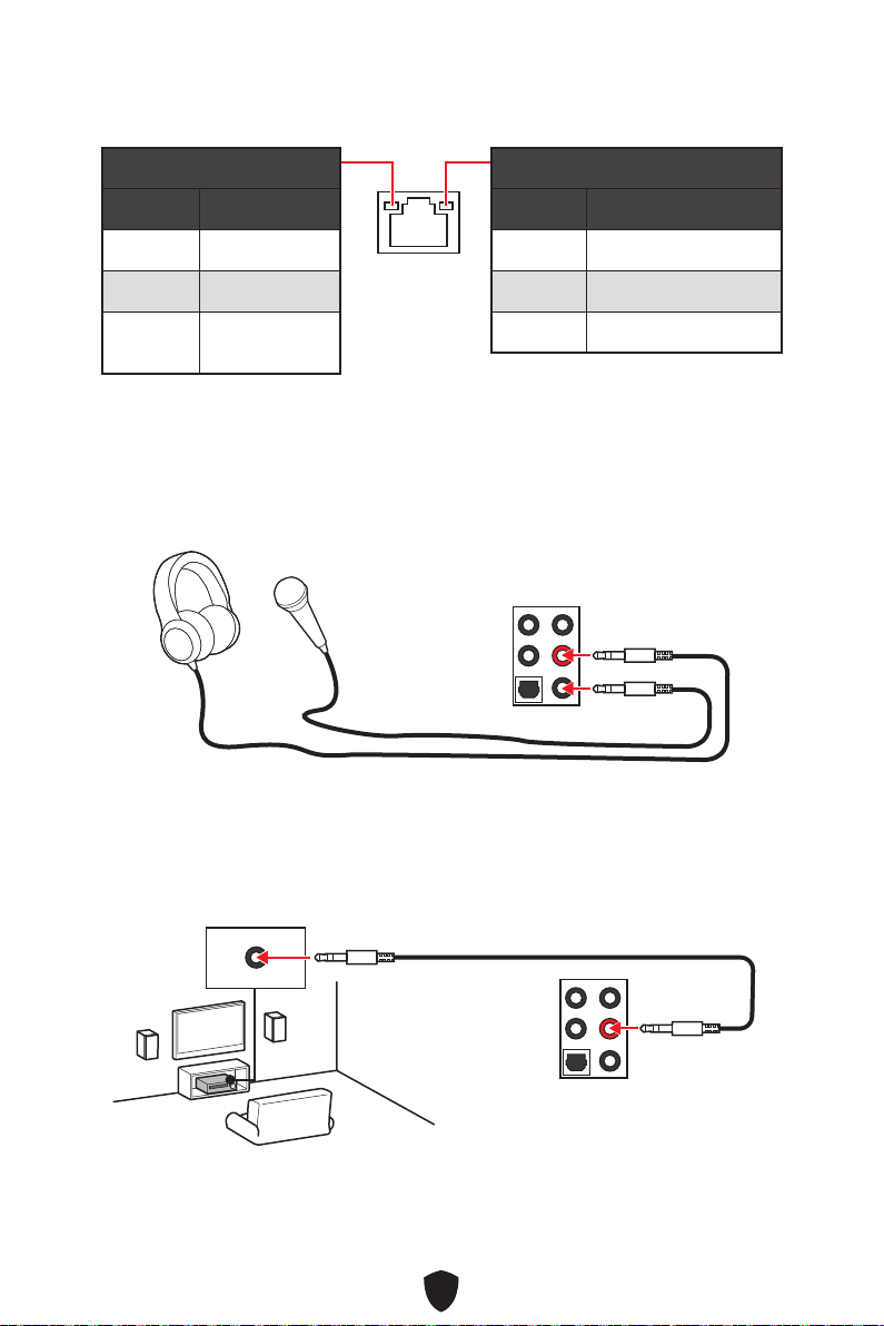
24
10 Mbps
100/1000 Mbps
2.5 Gbps
AUDIO INPUT

25
AUDIO INPUT
Rear Front
Center/
Subwoofer
AUDIO INPUT
Rear Front
Center/
Subwoofer
AUDIO INPUT
Rear Front
Side Center/
Subwoofer

26
1.
2.
11
22
3.

27
CPU_FAN1
PUMP_FAN1
SYS_FAN5
SYS_FAN4
JARGB_V2_2
ATX_PWR1
JUSB4
JUSB3
CPU_PWR1
CPU_PWR2
DIMMA2
DIMMB1
DIMMB2
DIMMA1
JCI1
JFP1
JBAT1
JOCFS1
LED_SW1
SYS_FAN3
SYS_FAN2
SYS_FAN1
JDASH1
JPWRLED1
JTBT1
JARGB_V2_1
JRGB1
JAUD1
JUSB2
JUSB1
M2_5
M2_1
M2_2
M2_3
M2_4
PCI_E1
PCI_E2
PCI_E3
JFP2
JTPM1

28
50.85 mm

29
DIMMA1 DIMMB1
DIMMA2 DIMMB2
DIMMA2
DRAM Frequency
DIMMA2 DIMMA2
DIMMB2
DIMMA1
DIMMA2
DIMMB1
DIMMB2

30
PCI_E1: PCIe 5.0 x16 (CPU)
PCI_E2
PCI_E3
PCI_E1

31
M2_1
M2_2
M2_4
M2_5
M2_3
1.
11
https://youtu.be/J88vcXeLido

32
2.
22
3.
33
4.
44
2260 SSD
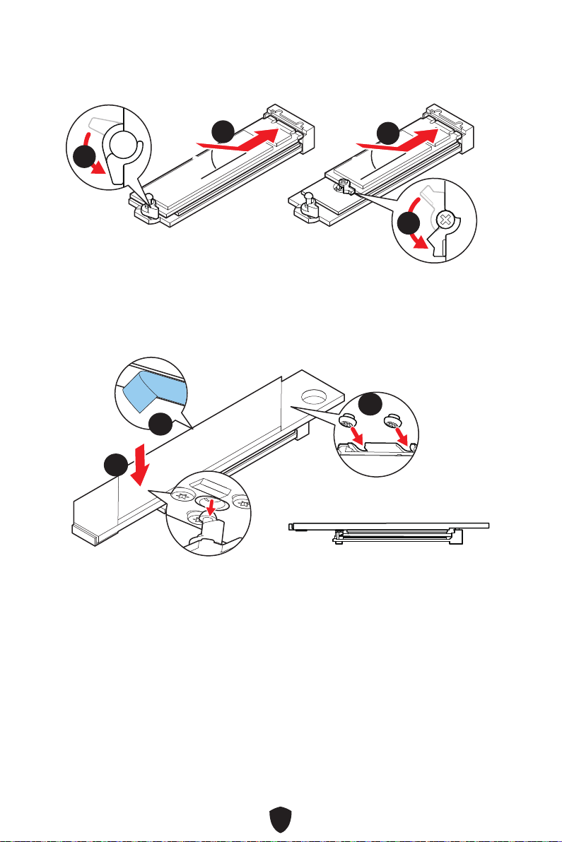
33
5.
6.
30º30º
30º30º
2280 SSD
2260 SSD
66
66
55
55
7.
8.
9.
99
88
77
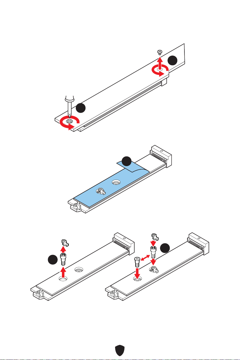
34
1.
11
11
2.
22
3.
33
33
22110 SSD
2260 SSD

35
4.
5.
30º30º
30º30º
22110 SSD
2280 SSD
2260 SSD
44
44
55
55
6.
7.
66
77
77

36
1.
11
11
11
11
2.
22
3.
33
2260 SSD

37
4.
5.
30º30º
30º30º
2280 SSD
2260 SSD
55
44
44
55
6.
7.
66
77
77 77
77
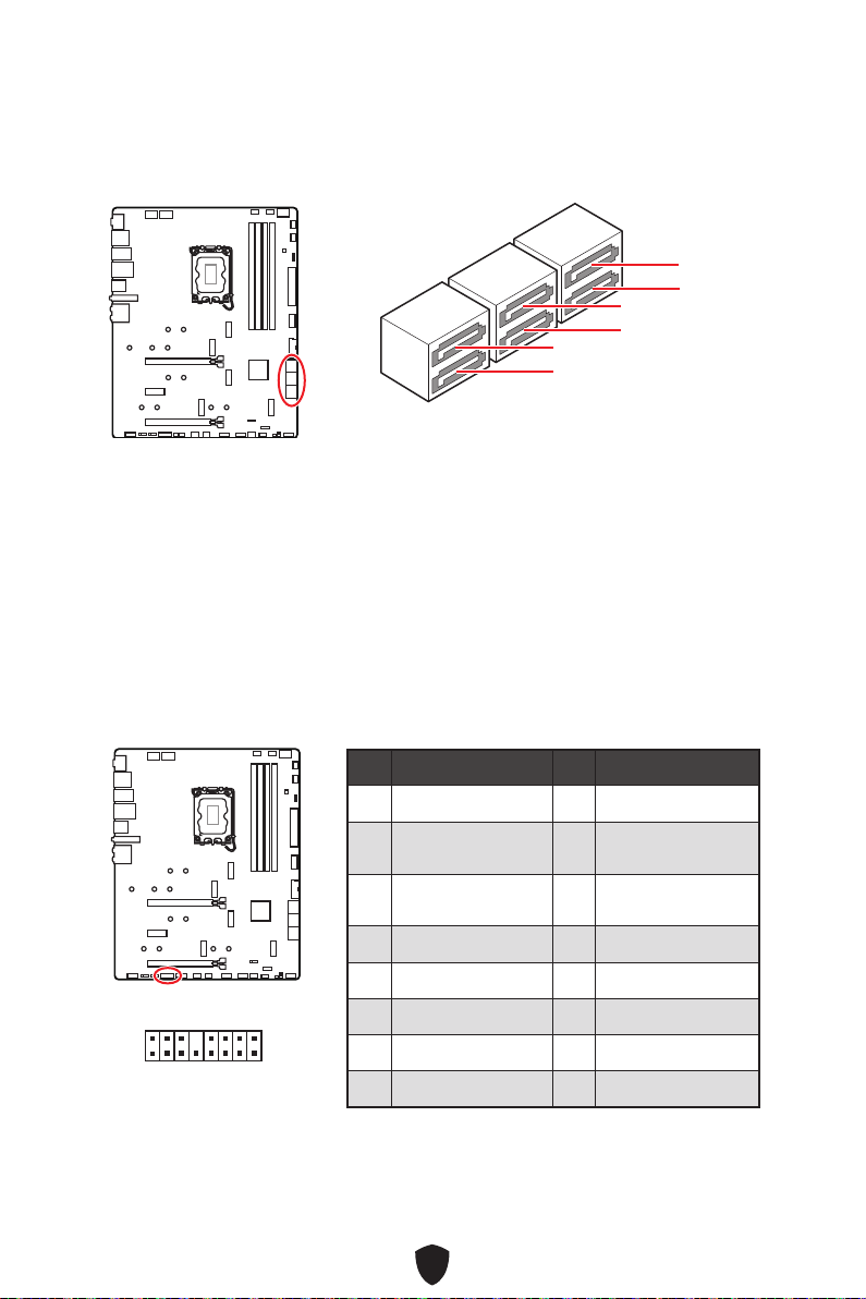
38
SATA5
SATA7
SATA_A1
SATA6
SATA8
SATA_A2
1
2 16
15
1 TBT_FORCE_PWR 2 TBT_S0IX_ENTRY_REQ
3
TBT_CIO_PLUG_
EVENT#
4 TBT_S0IX_ENTRY_ACK
5 SLP_S3#_TBT 6
TBT_PSON_
OVERRIDE_N
7 SLP_S5#_TBT 8 No Pin
9 Ground 10 SMBCLK_VSB
11 DG_PEWAKE# 12 SMBDATA_VSB
13 TBT_RTD3_PWR_EN 14 Ground
15 TBT_CARD_DET_R# 16 PD_IRQ#

39
1
2 10
9
1 MIC L 2 Ground
3 MIC R 4 NC
5 Head Phone R 6 MIC Detection
7 SENSE_SEND 8 No Pin
9 Head Phone L 10 Head Phone Detection
1
2 10
9
Reserved
JFP1
HDD LED
1
JFP2

40
CPU_PWR1~2
1 Ground 2 Ground
3 Ground 4 Ground
5 +12V 6 +12V
7 +12V 8 +12V
ATX_PWR1
1 +3.3V 2 +3.3V
3 Ground 4 +5V
5 Ground 6 +5V
7 Ground 8 PWR OK
9 5VSB 10 +12V
11 +12V 12 +3.3V
13 +3.3V 14 -12V
15 Ground 16 PS-ON#
17 Ground 18 Ground
19 Ground 20 Res
21 +5V 22 +5V
23 +5V 24 Ground
5
4 1
8
CPU_PWR1~2
24
131
12
ATX_PWR1
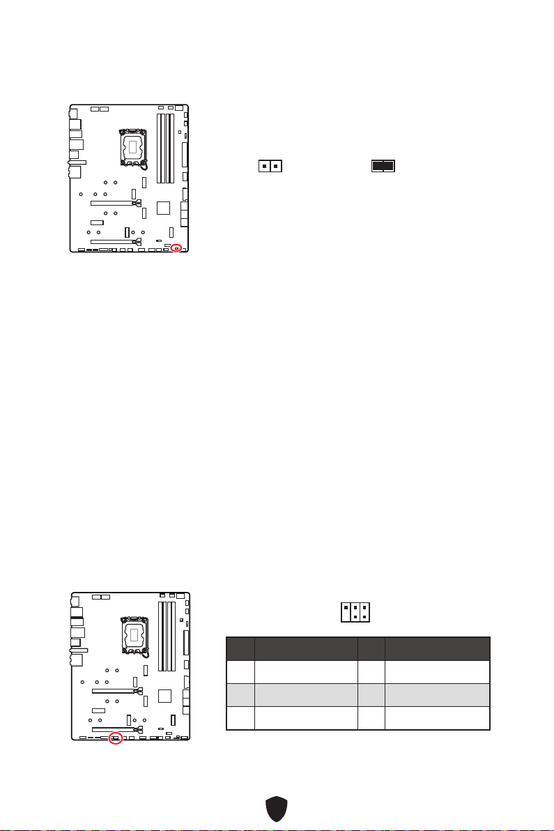
41
1. JCI1
2.
3. BIOS > SETTINGS > Security > Chassis Intrusion Configuration
4.
5. F10Yes
6.
1. BIOS > SETTINGS > Security > Chassis Intrusion Configuration
2.
3. F10Yes
1 No Pin 2 NC
3
MCU_SMB_SCL_M
4 MCU_SMB_SDA_M
5 VCC5 6 Ground
1
2
5
6
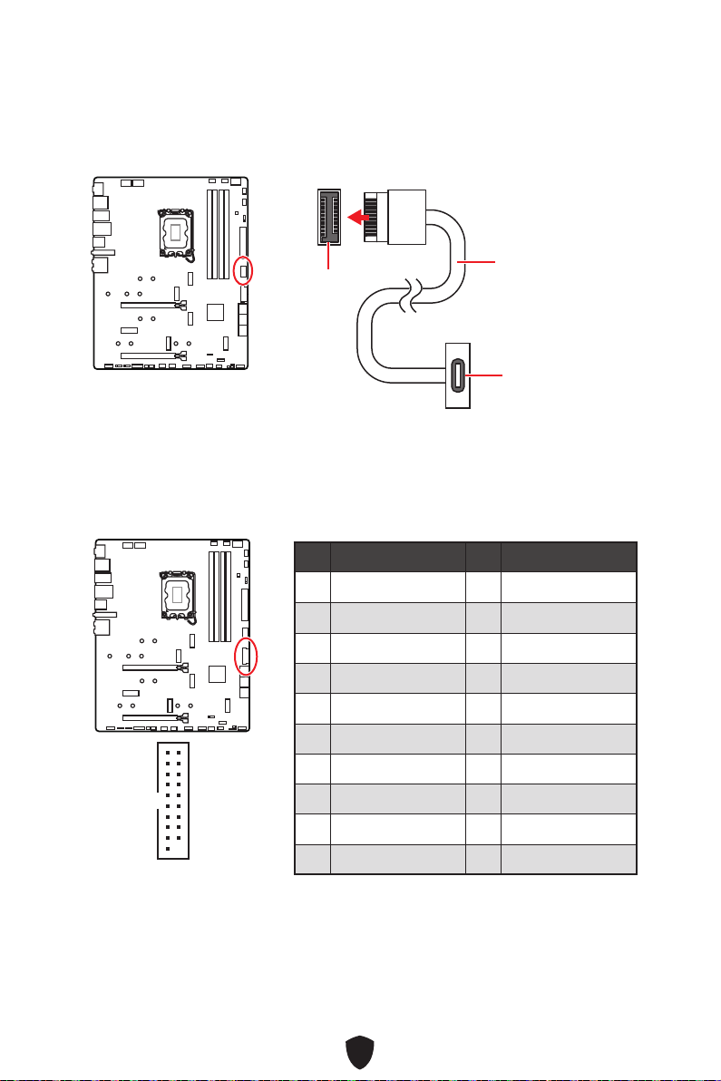
42
JUSB4
1 Power 2 USB3_RX_DN
3 USB3_RX_DP 4 Ground
5 USB3_TX_C_DN 6 USB3_TX_C_DP
7 Ground 8 USB2.0-
9 USB2.0+ 10 Ground
11 USB2.0+ 12 USB2.0-
13 Ground 14 USB3_TX_C_DP
15 USB3_TX_C_DN 16 Ground
17 USB3_RX_DP 18 USB3_RX_DN
19 Power 20 No Pin
1
10 11
20

43
1 VCC 2 VCC
3 USB0- 4 USB1-
5 USB0+ 6 USB1+
7 Ground 8 Ground
9 No Pin 10 NC
1
2 10
9
1 SPI Power 2 SPI Chip Select
3
Master In Slave Out
(SPI Data)
4
Master Out Slave In
(SPI Data)
5 Reserved 6 SPI Clock
7 Ground 8 SPI Reset
9 Reserved 10 No Pin
11 Reserved 12 Interrupt Request
1
2 12
11
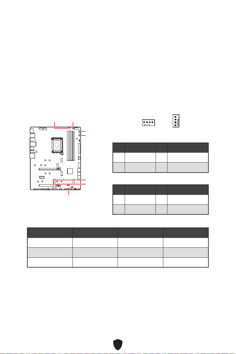
44
BIOS> HARDWARE MONITOR
CPU_FAN1
SYS_FAN2
SYS_FAN1
SYS_FAN3
PUMP_FAN1
SYS_FAN5
SYS_FAN4
1 Ground 2 +12V
3 Sense 4 Speed Control Signal
1 Ground 2 Voltage Control
3 Sense 4 NC
CPU_FAN1 2A 24W
PUMP_FAN1 3A 36W
SYS_FAN1~5 1A 12W
1
1

45
1.
2. JBAT1
3. JBAT1
4.
1.
2.

46
1
G
R
B
1
1
G
R
B
1 +12V 2 G
3 R 4 B
1
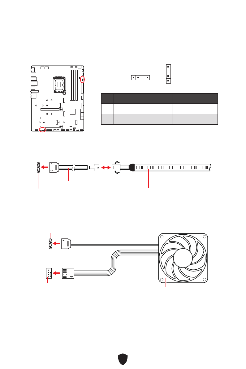
47
1 +5V 2 Data
3 No Pin 4 Ground
1
1
1
1
1
D
+5V

48
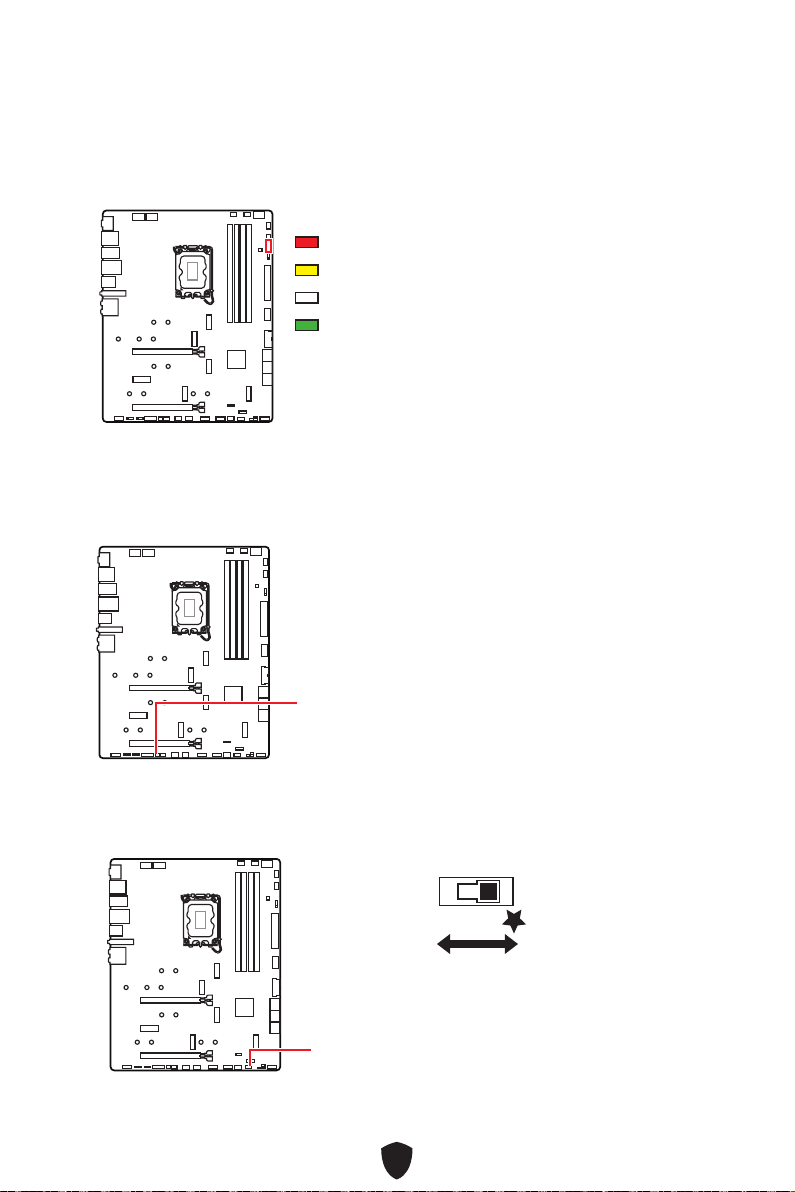
49
CPU
DRAM
VGA
BOOT
LED_SW1

50
Pre-EFI Initialization (PEI)
Driver Execution Environment (DXE)
Boot Device Selection (BDS)
(CD/DVD, HDD, USB, Network, Shell, …)
01
02
03
04
06
07
08
09
0B
0C - 0D
0E
0F
0 1 2 3 4 5 6 7
8 9 A B C D E F
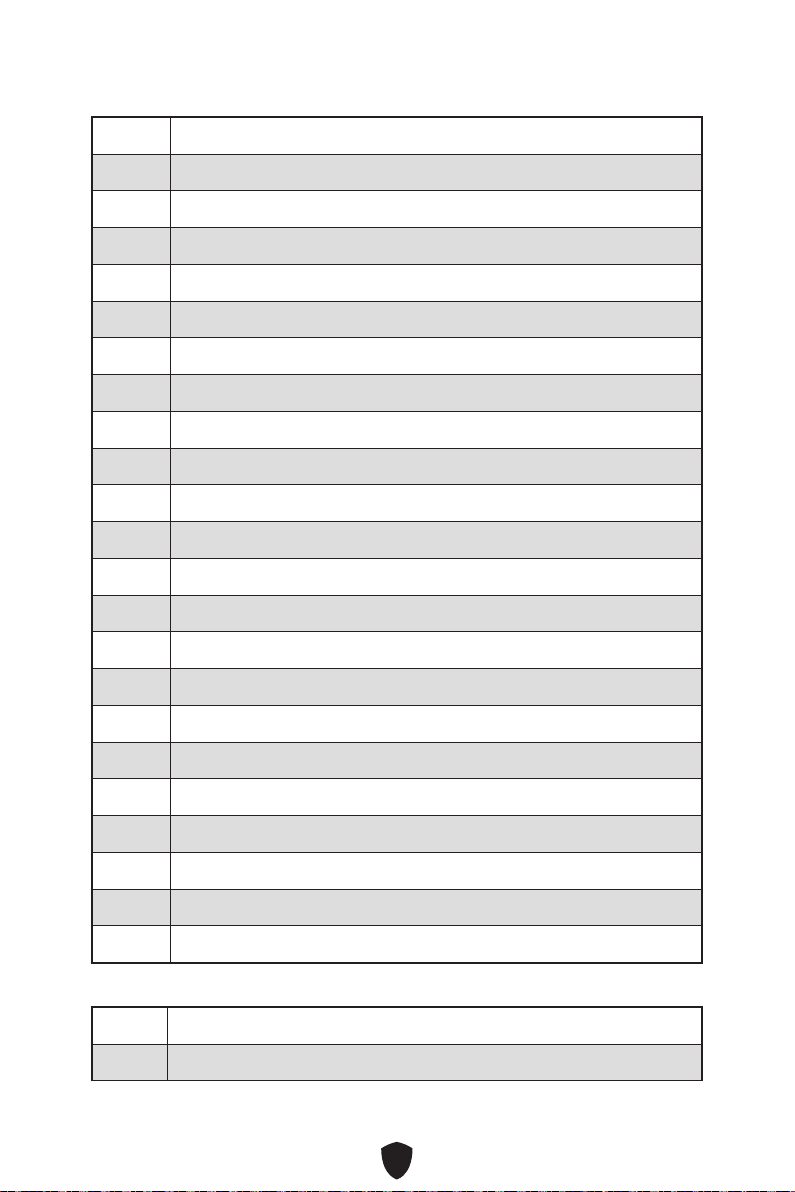
51
10
11
12 - 14
15
16 - 18
19
1A - 1C
2B
2C
2D
2E
2F
31
32
33
34
35
36
37
38 - 3A
3B
3C - 3E
4F
50
51
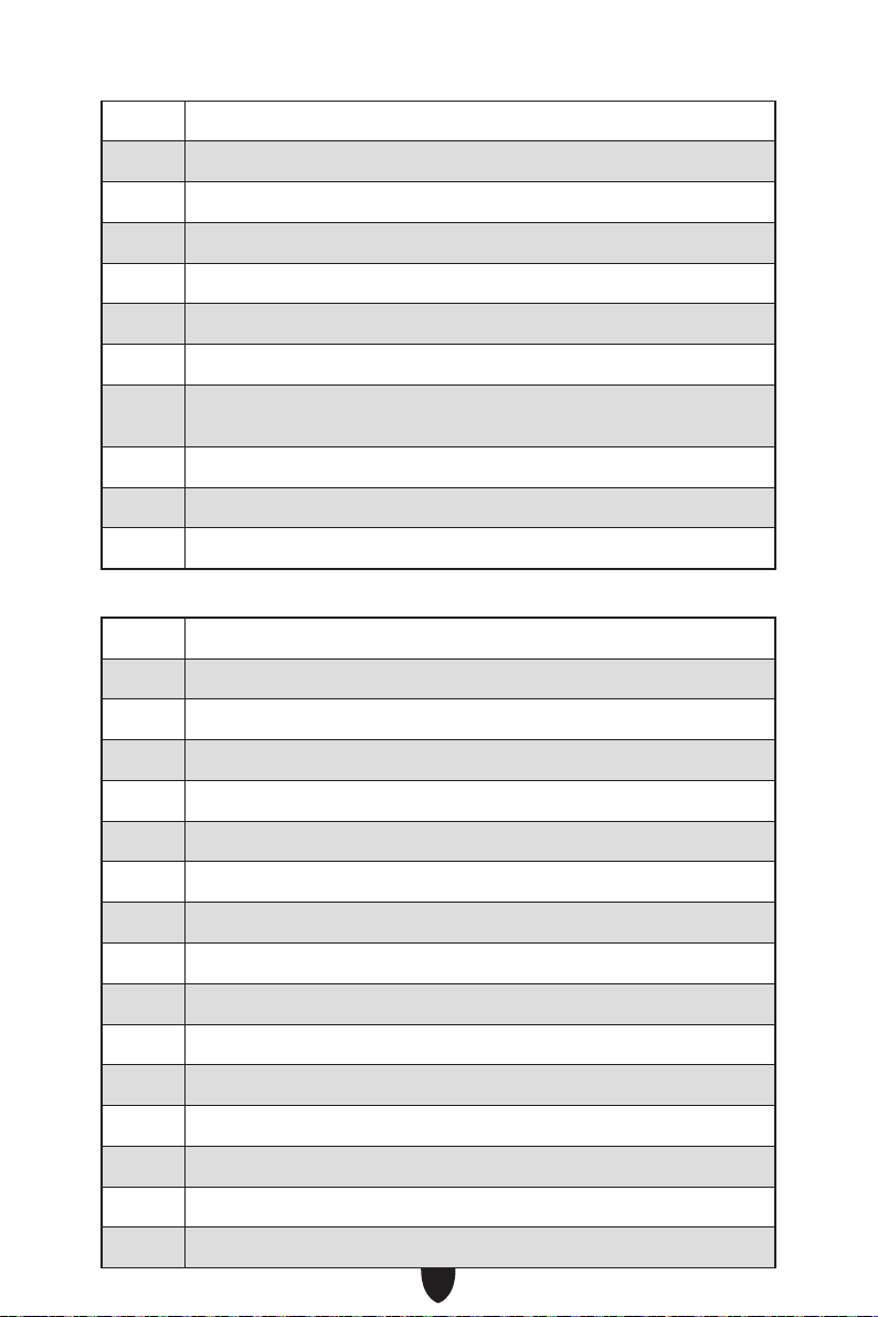
52
52
53
54
55
56
57
58
59
5A
5B
5C - 5F
60
61
62
63
64 - 67
68
69
6A
6B - 6F
70
71
72
73 - 77
78
79
7A - 7F

53
90
91
92
93
94 PCI Bus Enumeration 32
95
96
97
98
99
9A
9B
9C
9D
9E - 9F
A0
A1
A2
A3
A4
A5
A6
A7
A8
A9
AB
AD
AE
AF
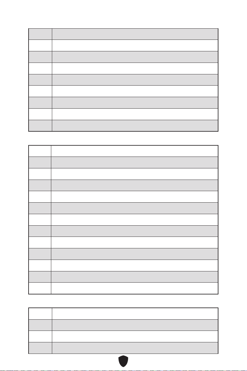
54
B0
B1
B2
B3
B4
B5
B6 Clean-up of NVRAM
B7
B8 - BF
D0
D1
D2
D3
D4
D5
D6
D7
D8
D9
DA
DB
DC
E0
E1
E2
E3 OS S3 wake vector call
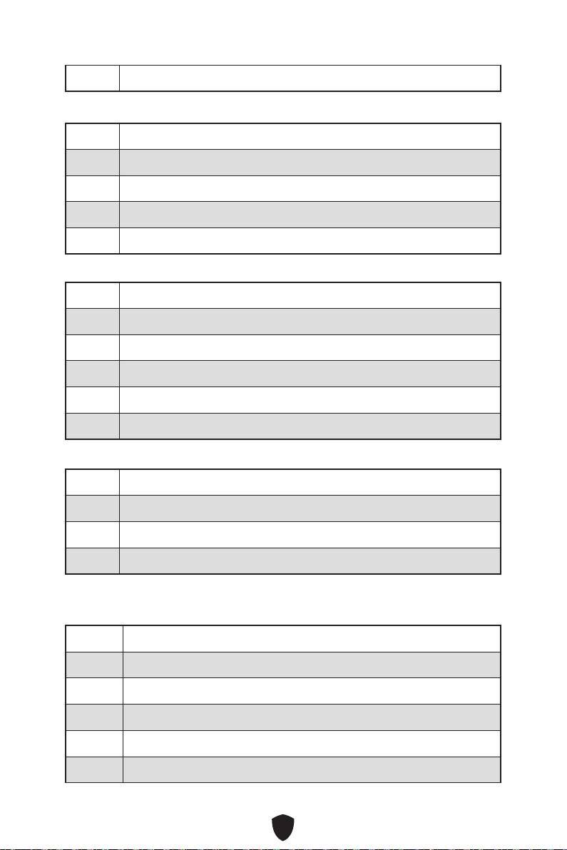
55
E4 - E7
E8
E9
EA
EB
EC - EF
F0
F1
F2
F3
F4
F5 - F7
F8
F9
FA
FB - FF
01
02
03
04
05
10

56
20
30
40
AC
AA
00 - 99

57
1.
2.
3. Restart
4. F11
5.
6. Press any key to boot from CD or DVD...
7.
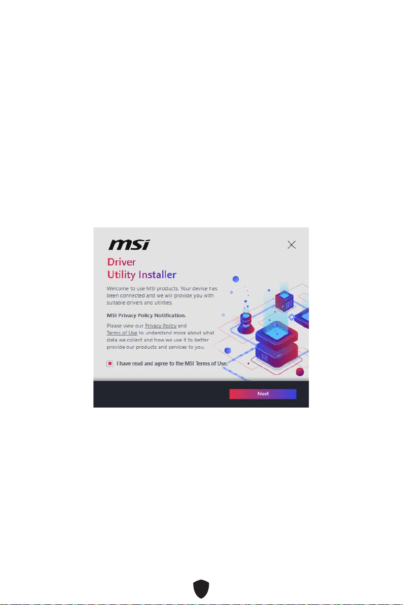
58
1.
2.
3.
4.

59
5. Select All Install
6. Finish
60
1.
2.
3.
4. DVDSetup
5. Drivers/Software
6. Install
7.
8. OK
9.
MSI Center
http://download.msi.com/manual/mb/MSICENTER.pdf

61
UEFI BIOS
1.
2.
3.
BIOS Mode: UEFI

62
F1:
F2:
F3:
F4:
F5:
F6:
F7:
F8:
F9:
F10:
F12:
Ctrl+F:
https://download.msi.com/archive/mnu_exe/mb/Intel700BIOSkr.pdf
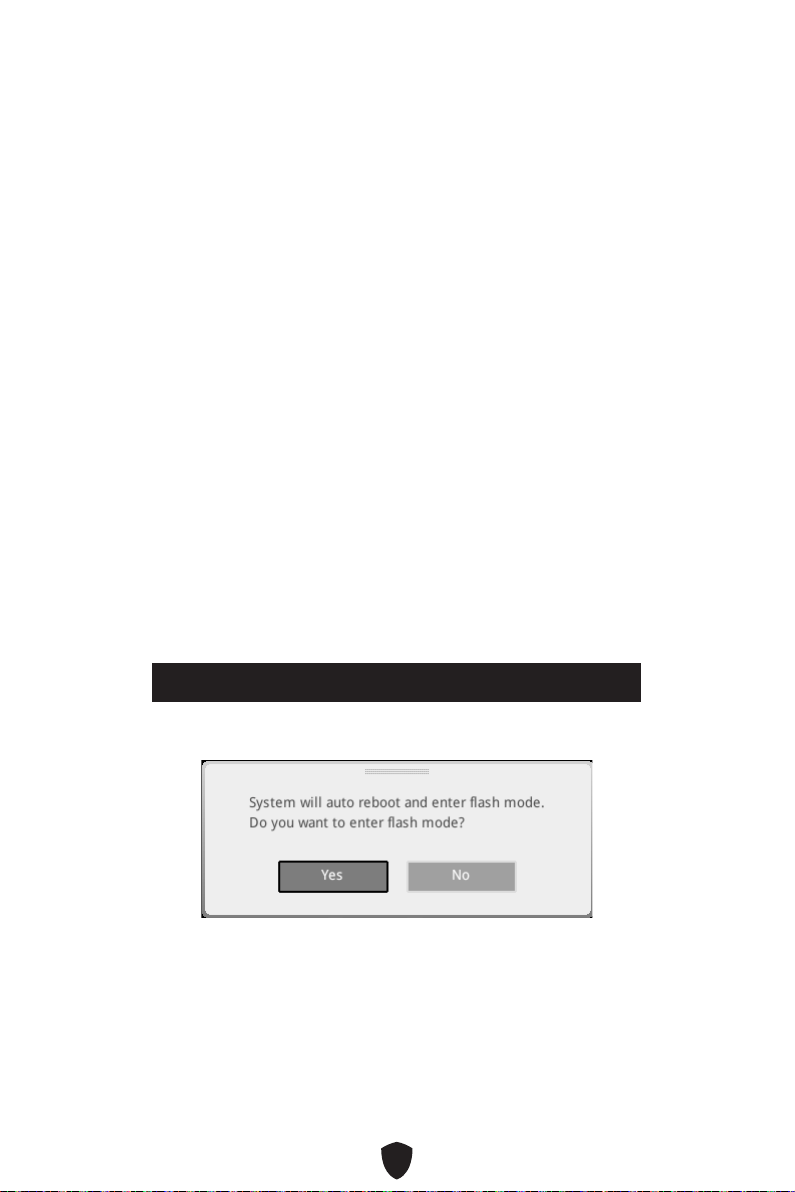
63
F6
1.
2.
3.
• Ctrl + F5
Press <Ctrl+F5> to activate M-Flash for BIOS update.
• DelM-FLASH
4.
5. Yes
6.

64
1. Support
2. Live UpdateAdvance
3. Install
4.
5.
6.
1.
2.
3. CPU_PWR1ATX_PWR1
4.
5.
6.

1
........................................................................................................................ 3
.............................................................................................................................. 15
...................................................................................................................... 20
...................................................................................................................... 21
.............................................................................................................. 22
.................................................................................... 24
............................................................................................. 24
................................................................................................................ 26
...................................................................................................................... 27
............................................................................................................... 28
............................................................................................................ 29
..................................................................................... 30
...................................................................................... 31
......................................................... 38
JTBT1: Thunderbolt Add-on Card Connector ...................................................... 38
........................................................................................... 39
................................................................................... 39
.................................................................. 40
............................................................................................... 41
..................................................................................... 41
................................................... 42
.................................................................................. 42
........................................................................................ 43
.......................................................................................... 43
...................................... 44
............................................................ 45
................................................................................................. 45
.......................................................................................... 46
.................................... 47
......................................................................................... 48

2
......................................................................................................... 49
................................................................................................... 49
................................................................................... 49
............................................................................. 49
........................................................................................................ 50
................................................................................................................ 50
................................................................................................... 50
.................................................................... 57
................................................. 58
MSI Center ............................................................................................................ 60
UEFI BIOS .................................................................................................................... 61
.............................................................................................................. 62
.............................................................................................................. 63
.............................................................................................................. 63

3
Intel® LGA1700 CPU

4
•
•
•
•
•
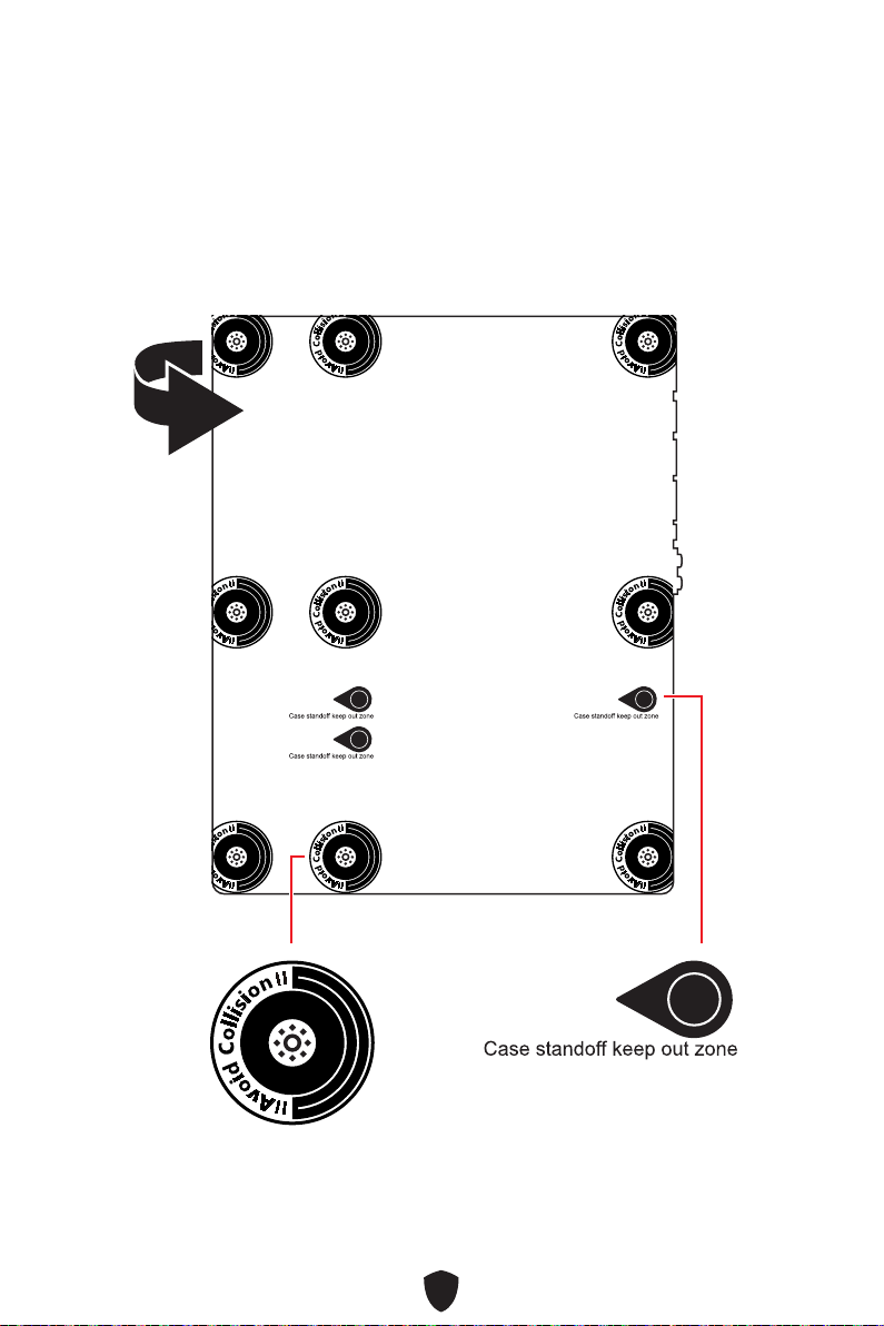
5

6
https://youtu.be/KMf9oIDsGes
11
22
33
66
44
55
77
88
99

7
DIMMA2 DIMMA2
DIMMB2
DIMMA1
DIMMA2
DIMMB1
DIMMB2
https://youtu.be/XiNmkDNZcZk

8
HDD LED
RESET SW
http://youtu.be/DPELIdVNZUI
JFP1
HDD LED
HDD LED -
HDD LED +
POWER LED -
POWER LED +
POWER LED
RESET SW
POWER SW
POWER LED+
POWER LED-
HDD LED
1
2 10
9
Power LED
Reserved
Power Switch
JFP1
Reset SwitchHDD LED

9
11
https://youtu.be/wWI6Qt51Wnc
3 kgf·cm*
*3 kgf·cm
= 0.3 N·m
= 2.6 lbf·in
22

10
http://youtu.be/gkDYyR_83I4
CPU_PWR1
CPU_PWR2
ATX_PWR1
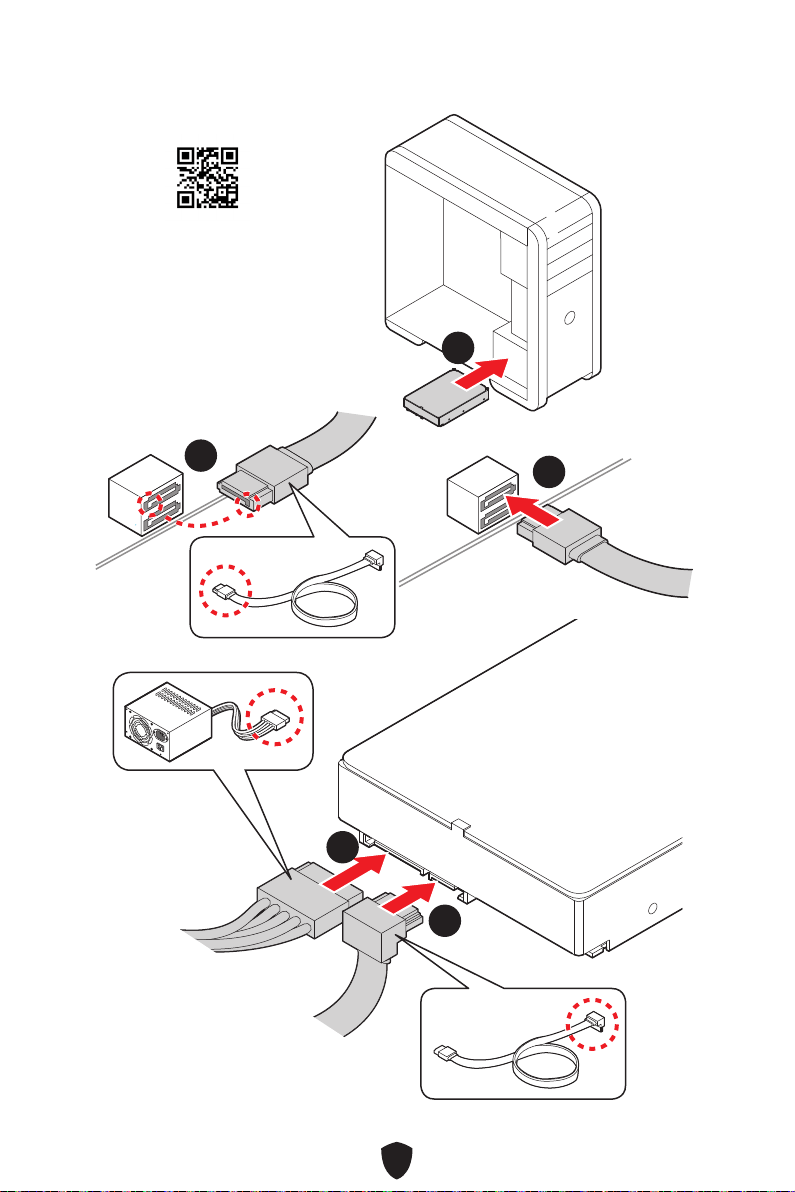
11
http://youtu.be/RZsMpqxythc
11
22
33
44
55

12
http://youtu.be/mG0GZpr9w_A
11
22
33
44
55
66

13

14
44
33
11
22

15
•
•
•
•
•
•
•
•
•
•
60Hz*
/
**
•
•

16
•
•
•
•
•
•
•
•
•
•
•
•
•
•
•
•
RAID
10*
RAID 10

17
Bluetooth®
Intel® Wi-Fi 6E
•
•

18
Asmedia ASM3242)
ATX
UEFI AMI BIOS

19
MSI Center
Intel Extreme Tuning Utility
MSI APP Player (BlueStacks)
CPU-Z MSI GAMING
Norton 360 Deluxe
Tile

20
MSI Center
• Gaming Mode
• Smart Priority
• Game Highlights
• Mystic Light
• Ambient Link
• Frozr AI Cooling
• User Scenario
• True Color
• Live Update
•
• Super Charger
• Devices Speed Up
• Smart Image Finder
• MSI Companion
•
•
•
•
•
•
•
• Memory Boost
•
•
•
•
•
•
•
•
•
•
•
•
•
• Audio Boost 5
RGB Support
• Mystic Light
•
•
• Ambient Link Support
BIOS
•

21
•
•
•
•
•
•
•
•
•
•
MSI Center

22
1
2
3
4
5
6
7
8
11 77
88 101099 14141313
55 66
12121111
3322 44
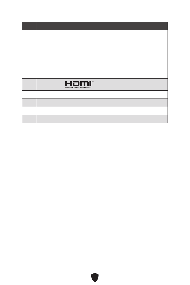
23
9
Turbo Fan
10
11
12
13
14

24
10 Mbps
100/ 1000 Mbps
2.5 Gbps
AUDIO INPUT
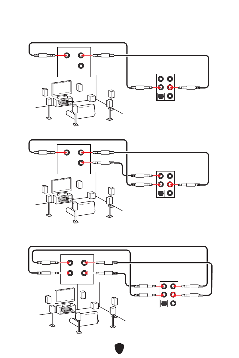
25
AUDIO INPUT
Rear Front
Center/
Subwoofer
AUDIO INPUT
Rear Front
Center/
Subwoofer
AUDIO INPUT
Rear Front
Side Center/
Subwoofer

26
1.
2.
11
22
3.

27
CPU_FAN1
PUMP_FAN1
SYS_FAN5
SYS_FAN4
JARGB_V2_2
ATX_PWR1
JUSB4
JUSB3
CPU_PWR1
CPU_PWR2
DIMMA2
DIMMB1
DIMMB2
DIMMA1
JCI1
JFP1
JBAT1
JOCFS1
LED_SW1
SYS_FAN3
SYS_FAN2
SYS_FAN1
JDASH1
JPWRLED1
JTBT1
JARGB_V2_1
JRGB1
JAUD1
JUSB2
JUSB1
M2_5
M2_1
M2_2
M2_3
M2_4
PCI_E1
PCI_E2
PCI_E3
JFP2
JTPM1

28
50.85 mm

29
DIMMA1 DIMMB1
DIMMA2 DIMMB2
DIMMA2
DRAM Frequency
DIMMA2 DIMMA2
DIMMB2
DIMMA1
DIMMA2
DIMMB1
DIMMB2

30
PCI_E1
PCI_E2
PCI_E3
PCI_E1
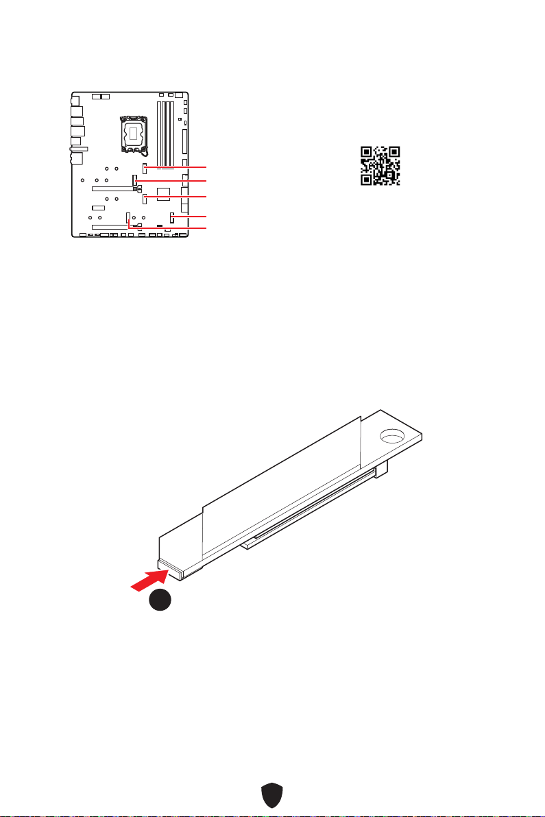
31
M2_1
M2_2
M2_4
M2_5
M2_3
1.
11
https://youtu.be/J88vcXeLido
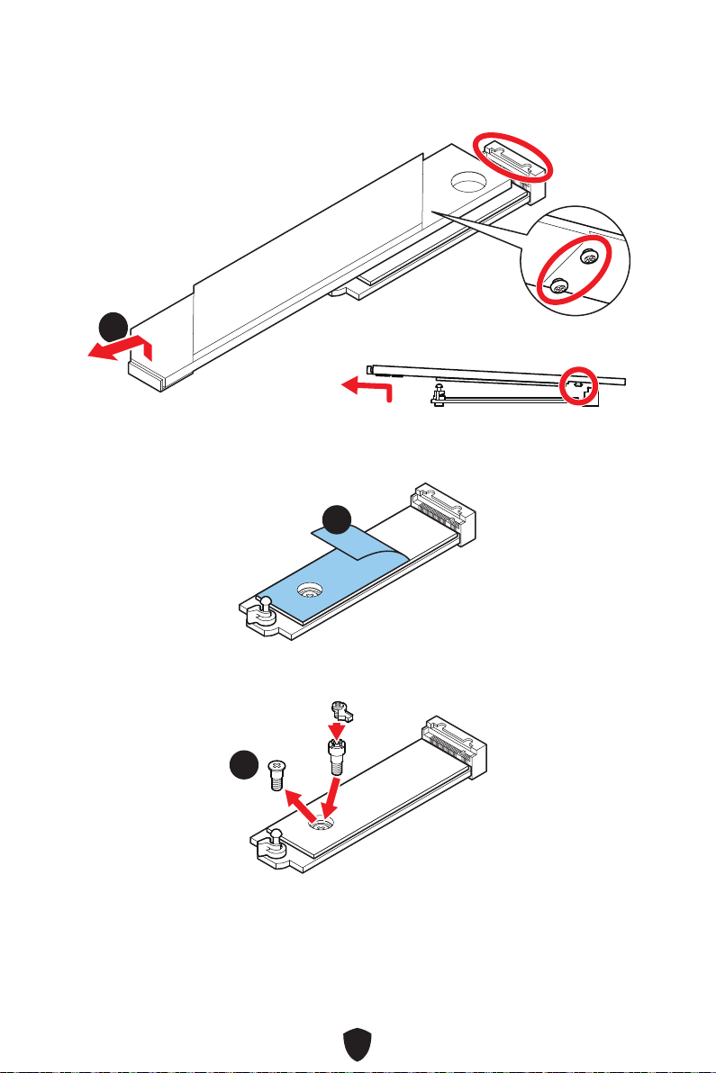
32
2.
22
3.
33
4.
44
2260 SSD
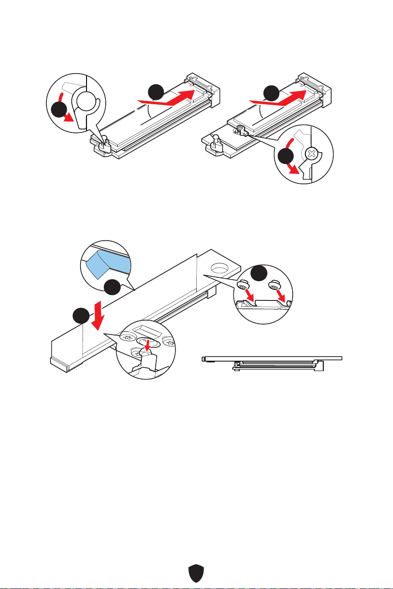
33
5.
6.
30º30º
30º30º
2280 SSD
2260 SSD
66
66
55
55
7.
8.
9.
99
88
77
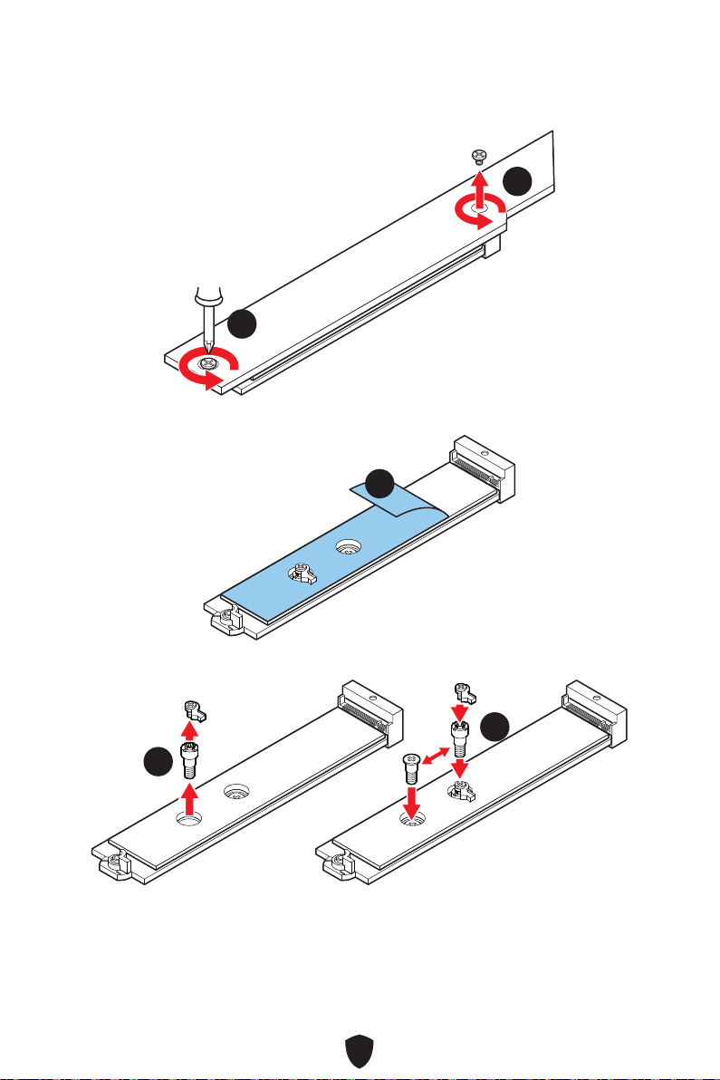
34
1.
11
11
2.
22
3.
33
33
22110 SSD
2260 SSD

35
4.
5.
30º30º
30º30º
22110 SSD
2280 SSD
2260 SSD
44
44
55
55
6.
7.
66
77
77
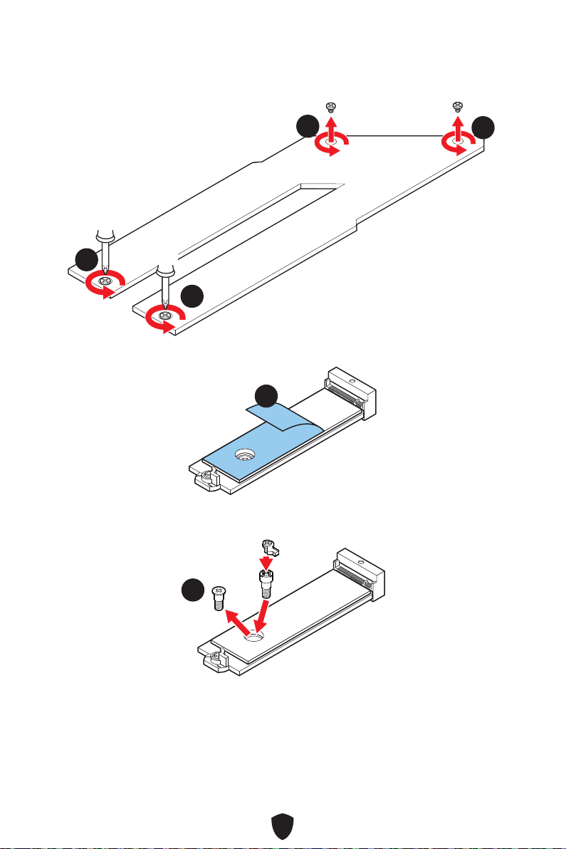
36
1.
11
11
11
11
2.
22
3.
33
2260 SSD

37
4.
5.
30º30º
30º30º
2280 SSD
2260 SSD
55
44
44
55
6.
7.
66
77
77 77
77
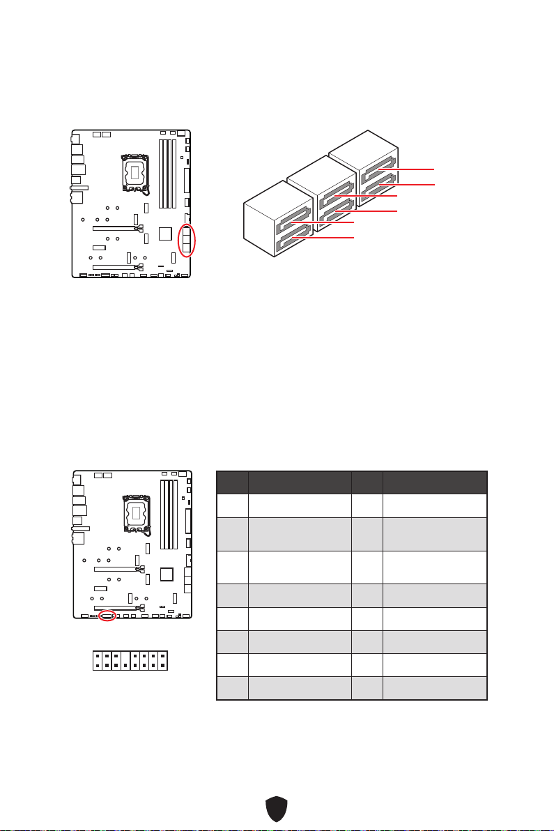
38
SATA5
SATA7
SATA_A1
SATA6
SATA8
SATA_A2
JTBT1: Thunderbolt Add-on Card Connector
This connector allows you to connect the add-on Thunderbolt I/O card.
1
2 16
15
1 TBT_FORCE_PWR 2 TBT_S0IX_ENTRY_REQ
3
TBT_CIO_PLUG_
EVENT#
4 TBT_S0IX_ENTRY_ACK
5 SLP_S3#_TBT 6
TBT_PSON_
OVERRIDE_N
7 SLP_S5#_TBT 8 No Pin
9 Ground 10 SMBCLK_VSB
11 DG_PEWAKE# 12 SMBDATA_VSB
13 TBT_RTD3_PWR_EN 14 Ground
15 TBT_CARD_DET_R# 16 PD_IRQ#

39
1
2 10
9
1 MIC L 2 Ground
3 MIC R 4 NC
5 Head Phone R 6 MIC Detection
7 SENSE_SEND 8 No Pin
9 Head Phone L 10 Head Phone Detection
1
2 10
9
Power LED
Reserved
Power Switch
JFP1
Reset SwitchHDD LED
1
JFP2
Buzzer
Speaker

40
CPU_PWR1~2
1 Ground 2 Ground
3 Ground 4 Ground
5 +12V 6 +12V
7 +12V 8 +12V
ATX_PWR1
1 +3.3V 2 +3.3V
3 Ground 4 +5V
5 Ground 6 +5V
7 Ground 8 PWR OK
9 5VSB 10 +12V
11 +12V 12 +3.3V
13 +3.3V 14 -12V
15 Ground 16 PS-ON#
17 Ground 18 Ground
19 Ground 20 Res
21 +5V 22 +5V
23 +5V 24 Ground
5
4 1
8
CPU_PWR1~2
24
131
12
ATX_PWR1
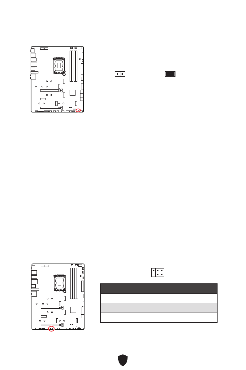
41
1. JCI1
2.
3. BIOS > SETTINGS > Security > Chassis Intrusion Configuration
4. Chassis IntrusionEnabled
5. F10Enter
6.
1. BIOS > SETTINGS > Security > Chassis Intrusion Configuration
2. Chassis IntrusionReset
3. F10
1 No Pin 2 NC
3
MCU_SMB_SCL_M
4 MCU_SMB_SDA_M
5 VCC5 6 Ground
1
2
5
6
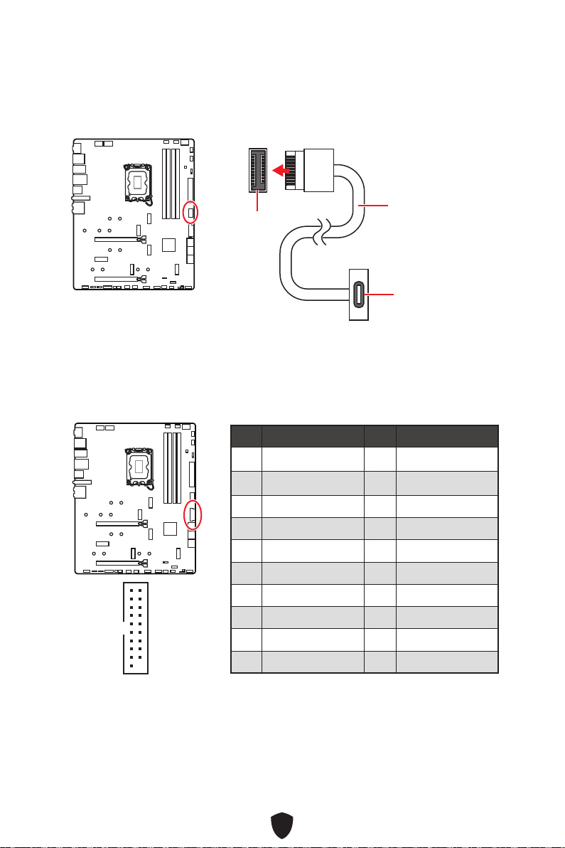
42
JUSB4
1 Power 2 USB3_RX_DN
3 USB3_RX_DP 4 Ground
5 USB3_TX_C_DN 6 USB3_TX_C_DP
7 Ground 8 USB2.0-
9 USB2.0+ 10 Ground
11 USB2.0+ 12 USB2.0-
13 Ground 14 USB3_TX_C_DP
15 USB3_TX_C_DN 16 Ground
17 USB3_RX_DP 18 USB3_RX_DN
19 Power 20 No Pin
1
10 11
20

43
1 VCC 2 VCC
3 USB0- 4 USB1-
5 USB0+ 6 USB1+
7 Ground 8 Ground
9 No Pin 10 NC
1
2 10
9
1 SPI Power 2 SPI Chip Select
3
Master In Slave Out
(SPI Data)
4
Master Out Slave In
(SPI Data)
5 Reserved 6 SPI Clock
7 Ground 8 SPI Reset
9 Reserved 10 No Pin
11 Reserved 12 Interrupt Request
1
2 12
11
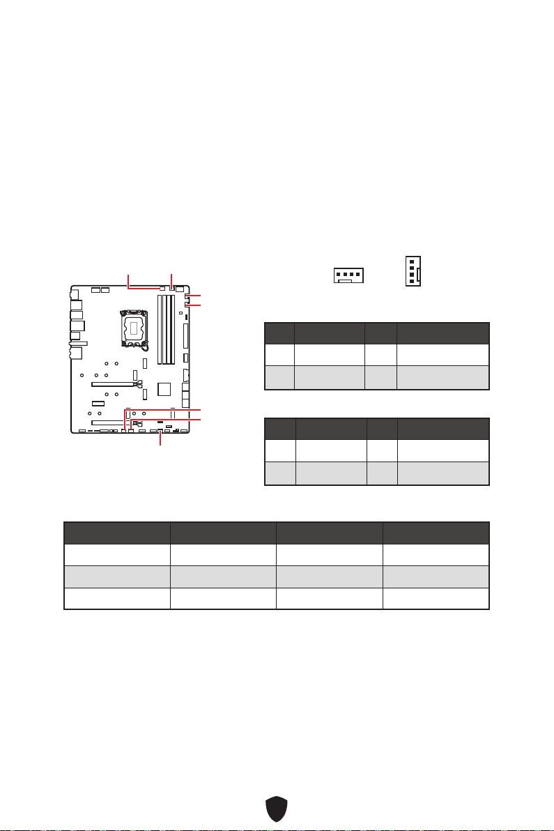
44
BIOS > HARDWARE MONITOR
CPU_FAN1
SYS_FAN2
SYS_FAN1
SYS_FAN3
PUMP_FAN1
SYS_FAN5
SYS_FAN4
1 Ground 2 +12V
3 Sense 4 Speed Control Signal
1 Ground 2 Voltage Control
3 Sense 4 NC
CPU_FAN1 2A 24W
PUMP_FAN1 3A 36W
SYS_FAN1~5 1A 12W
1
1

45
1.
2. JBAT1
3. JBAT1
4.
1.
2.

46
1
G
R
B
1
1
G
R
B
1 +12V 2 G
3 R 4 B
1

47
1 +5V 2 Data
3 No Pin 4 Ground
1
1
1
1
1
D
+5V

48

49
CPU
DRAM
VGA
BOOT
LED_SW1
LED_OFF
LED_ON

50
Security (SEC)
Pre-EFI Initialization (PEI)
Driver Execution Environment (DXE)
Boot Device Selection (BDS)
01
02
03
04
06
07
08
09
0B
0C - 0D
0E
0F
0 1 2 3 4 5 6 7
8 9 A B C D E F
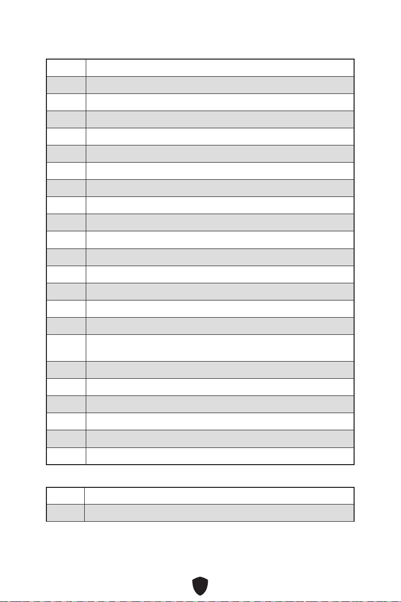
51
10
11
12 - 14
15
16 - 18
19
1A - 1C
2B
2C
2D
2E
2F
31
32
33
34
35
36
37
38 - 3A
3B
3C - 3E
4F
50
51
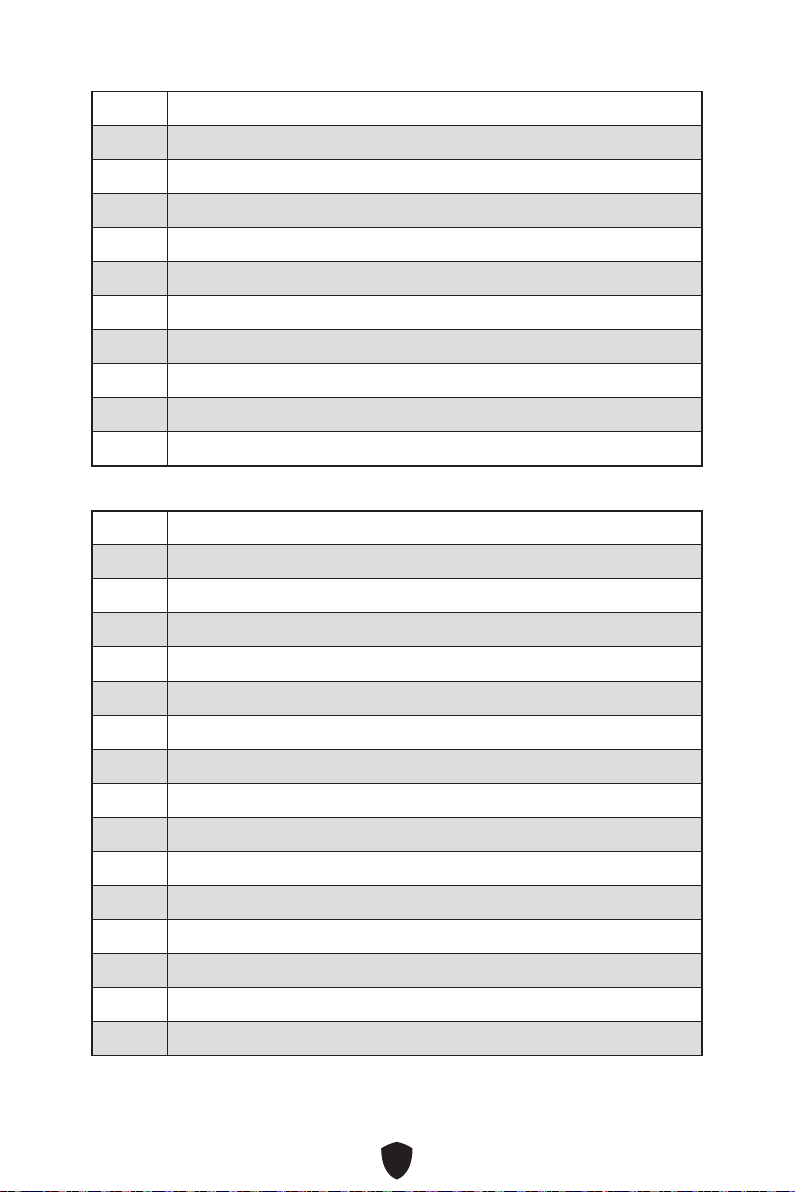
52
52
53
54
55
56
57
58
59
5A
5B
5C - 5F
60
61
62
63
64 - 67
68
69
6A
6B - 6F
70
71
72
73 - 77
78
79
7A - 7F

53
90
91
92
93
94
95
96
97
98
99
9A
9B USB Reset
9C
9D
9E -9F
A0
A1 IDE Reset
A2
A3
A4
A5 SCSI Reset
A6
A7
A8
A9
AB
AD
AE
AF

54
B0
B1
B2
B3
B4
B5
B6
B7
B8 - BF
D0
D1
D2
D3
D4
D5
D6
D7
D8
D9
DA
DB
DC
E0
E1
E2
E3
55
E4 - E7
E8
E9
EA
EB
EC - EF
F0
F1
F2
F3
F4
F5 - F7
F8
F9
FA
FB - FF
01
02
03
04
05
10
20

56
30
40
AC
AA
00 - 99

57
1.
2.
3.
4. F11
5.
6. Press any key to boot from CD or DVD...
7.
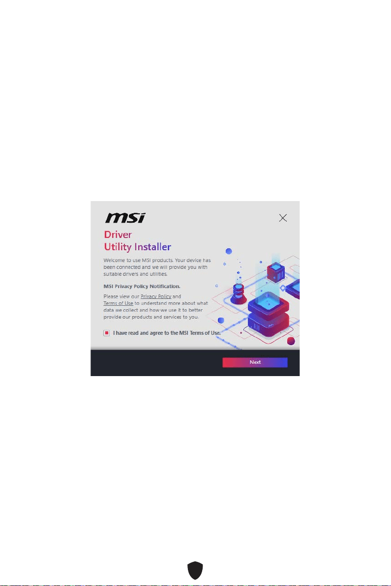
58
1.
2.
3.
4.

59
5.
6.
60
1.
2.
3.
4. DVDSetup
5.
6.
7.
8.
9.
MSI Center
http://download.msi.com/manual/mb/MSICENTERCT.pdf

61
UEFI BIOS
There is no GOP (Graphics Output protocol) support detected in this graphics card.
1.
2. Delete
3.
BIOS Mode: UEFI

62
HELP
Delete
F1:
F2:
F3:
F4:
F5:
F6:
F7:
F8:
F9:
F10:
F12:
Ctrl+F:
https://download.msi.com/archive/mnu_exe/mb/Intel700BIOStc.pdf

63
F6
1.
2.
3.
• Ctrl + F5
Press <Ctrl+F5> to activate M-Flash for BIOS update.
• DelM-FLASH
4.
5. Yes
6.

64
1. Support
2. Live UpdateAdvance
3. Install
4.
5.
6.
1.
2.
3. CPU_PWR1ATX_PWR1
4.
5.
6.

1
........................................................................................................................ 3
.............................................................................................................................. 15
...................................................................................................................... 20
.................................................................................................................. 21
.............................................................................................................. 22
........................................................................................... 24
........................................................................................................ 24
................................................................................................................ 26
...................................................................................................................... 27
............................................................................................................... 28
............................................................................................................ 29
..................................................................................... 30
...................................................................................... 31
......................................................... 38
.......................................................................... 38
........................................................................................... 39
.................................................................................... 39
.................................................................. 40
........................................................................................ 41
.................................................................................... 41
................................................... 42
.................................................................................. 42
........................................................................................ 43
.......................................................................................... 43
............................................. 44
.................................................................... 45
................................................................................................. 45
.......................................................................................... 46
.................................... 47
......................................................................................... 48
................................................................................................................. 49
................................................................................................... 49

2
................................................................................... 49
................................................................................. 49
................................................................................................... 50
................................................................................................................ 50
............................................................................................... 50
.................................................................... 57
.................................................... 58
MSI Center ............................................................................................................ 60
UEFI BIOS .................................................................................................................... 61
.............................................................................................................. 62
.............................................................................................................. 63
.............................................................................................................. 63

3
Intel® LGA1700 CPU

4
•
•
•
•
•
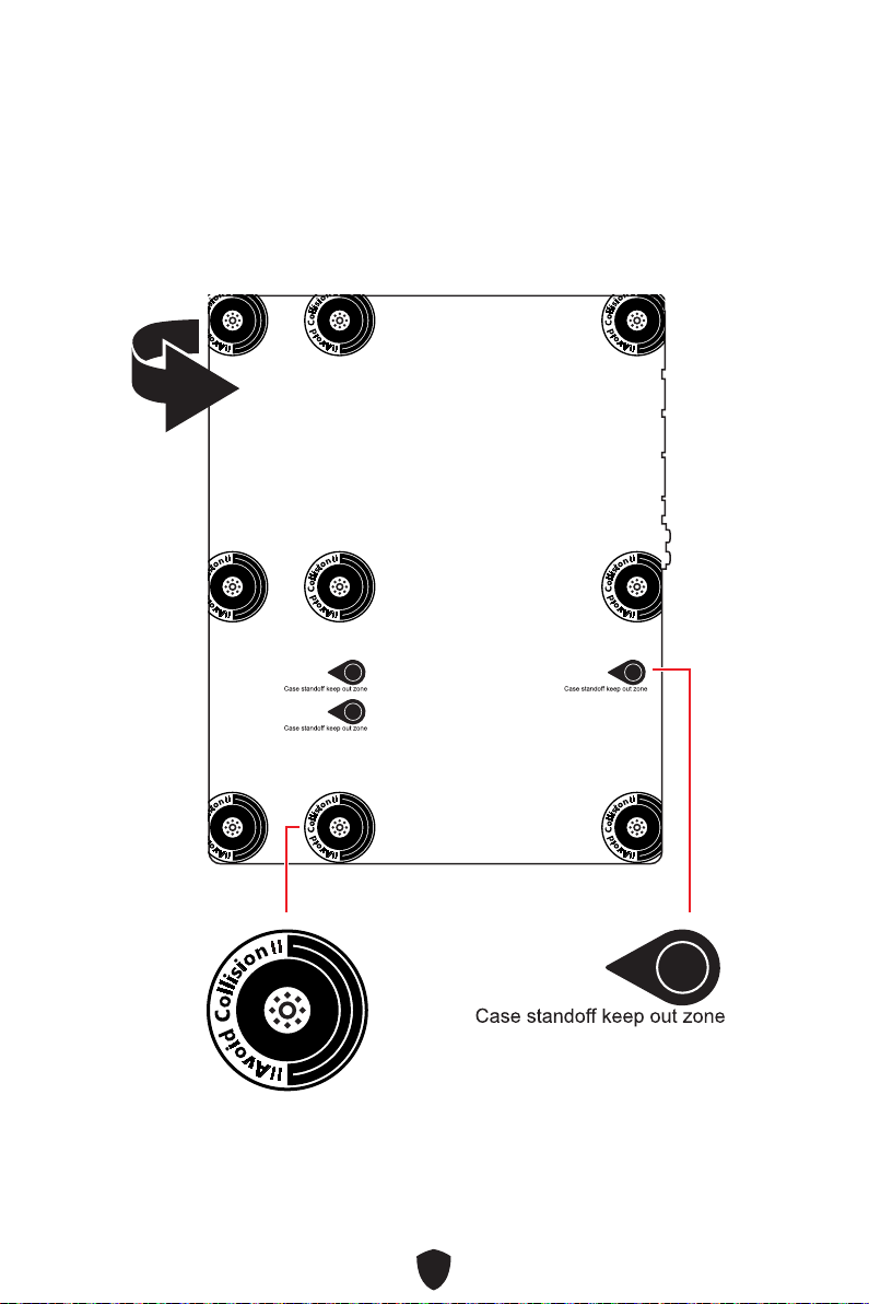
5

6
11
22
33
66
44
55
77
88
99
https://v.youku.com/v_show/
id_XNTE5NDQwNDY2NA==.html

7
DIMMA2 DIMMA2
DIMMB2
DIMMA1
DIMMA2
DIMMB1
DIMMB2
https://v.youku.com/v_show/id_
XNTE5NTg0NDM4NA==.html

8
HDD LED
RESET SW
JFP1
HDD LED
HDD LED -
HDD LED +
POWER LED -
POWER LED +
POWER LED
RESET SW
POWER SW
POWER LED+
POWER LED-
HDD LED
1
2 10
9
Power LED
Reserved
Power Switch
JFP1
Reset SwitchHDD LED
http://v.youku.com/v_show/id_
XNjcyMTczMzM2.html
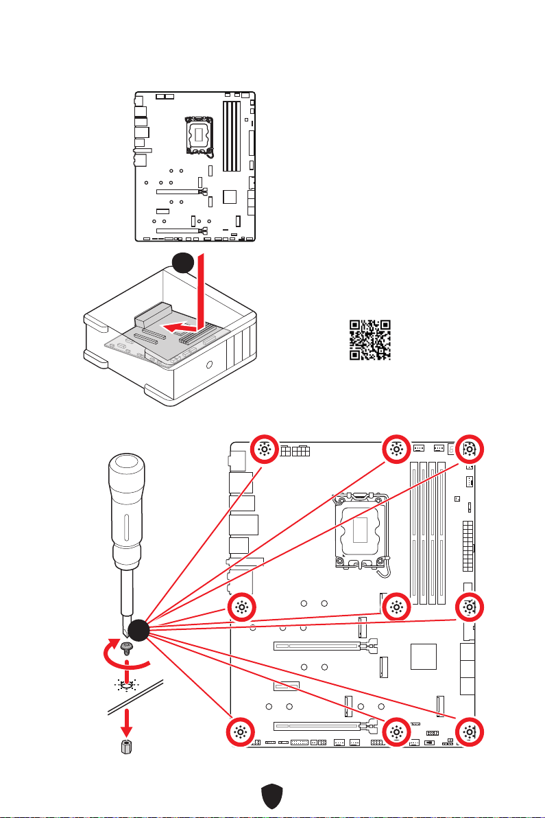
9
11
3 kgf·cm*
*3 kgf·cm
= 0.3 N·m
= 2.6 lbf·in
22
https://v.youku.com/v_show/id_
XNDUwMDUyNTkwOA==.html
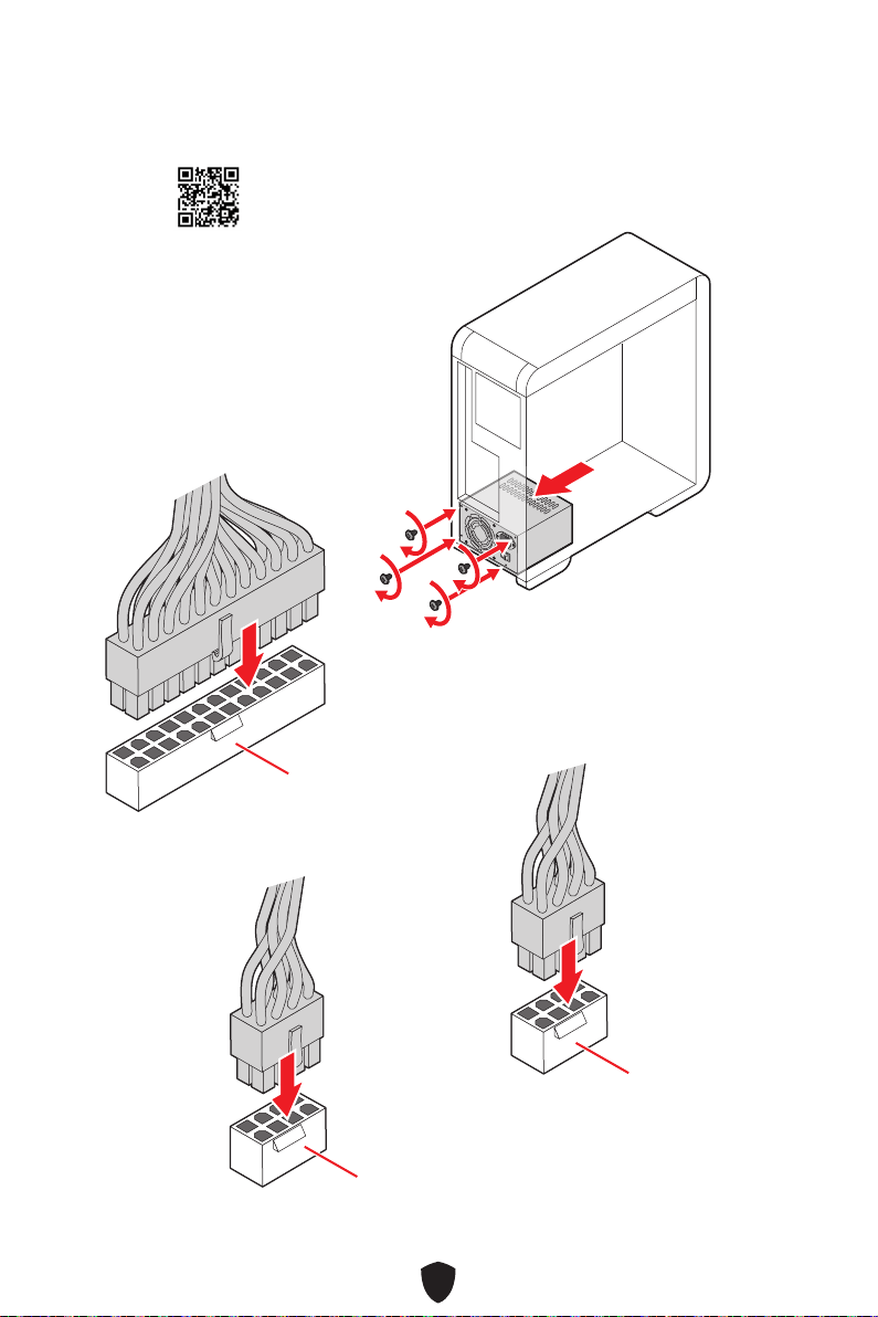
10
CPU_PWR1
CPU_PWR2
ATX_PWR1
http://v.youku.com/v_show/
id_XNDkzODU0MDQw.html
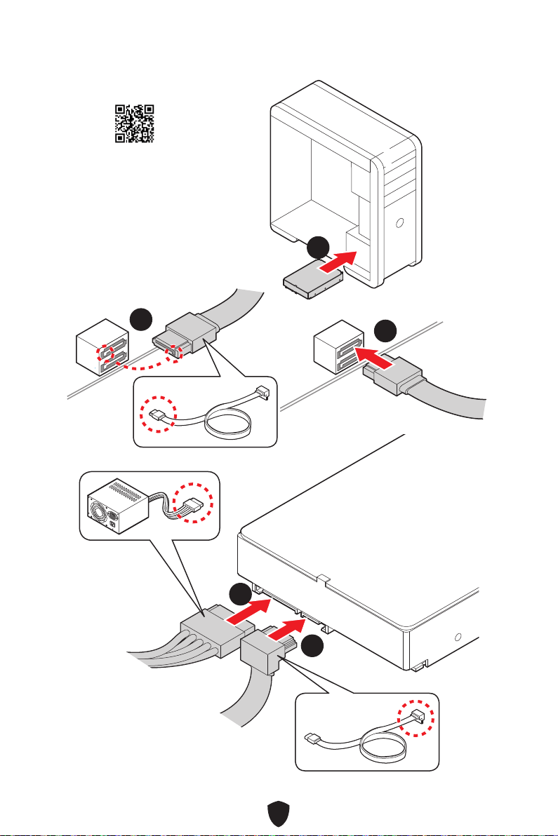
11
11
22
33
44
55
http://v.youku.com/v_show/
id_XNDkzODU5MTky.html
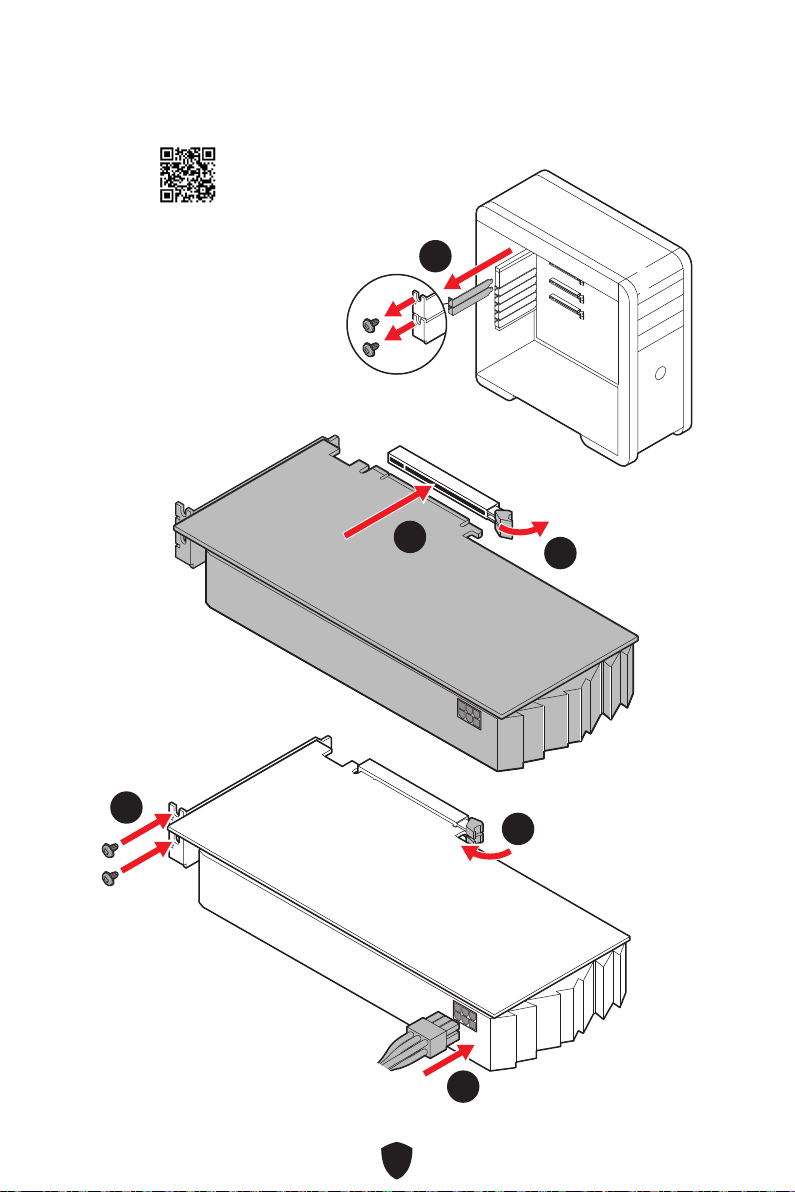
12
11
22
33
44
55
66
http://v.youku.com/v_show/id_
XNDkyOTc3MzQ4.html

13

14
44
33
11
22

15
CPU
•
•
•
•
•
•
•
•
•
•
60Hz*
/
**
•
•

16
•
•
•
•
•
•
•
•
•
•
•
•
•
•
•
•
RAID
10*
RAID 10
LAN

17
Intel® Wi-Fi 6E
•
•
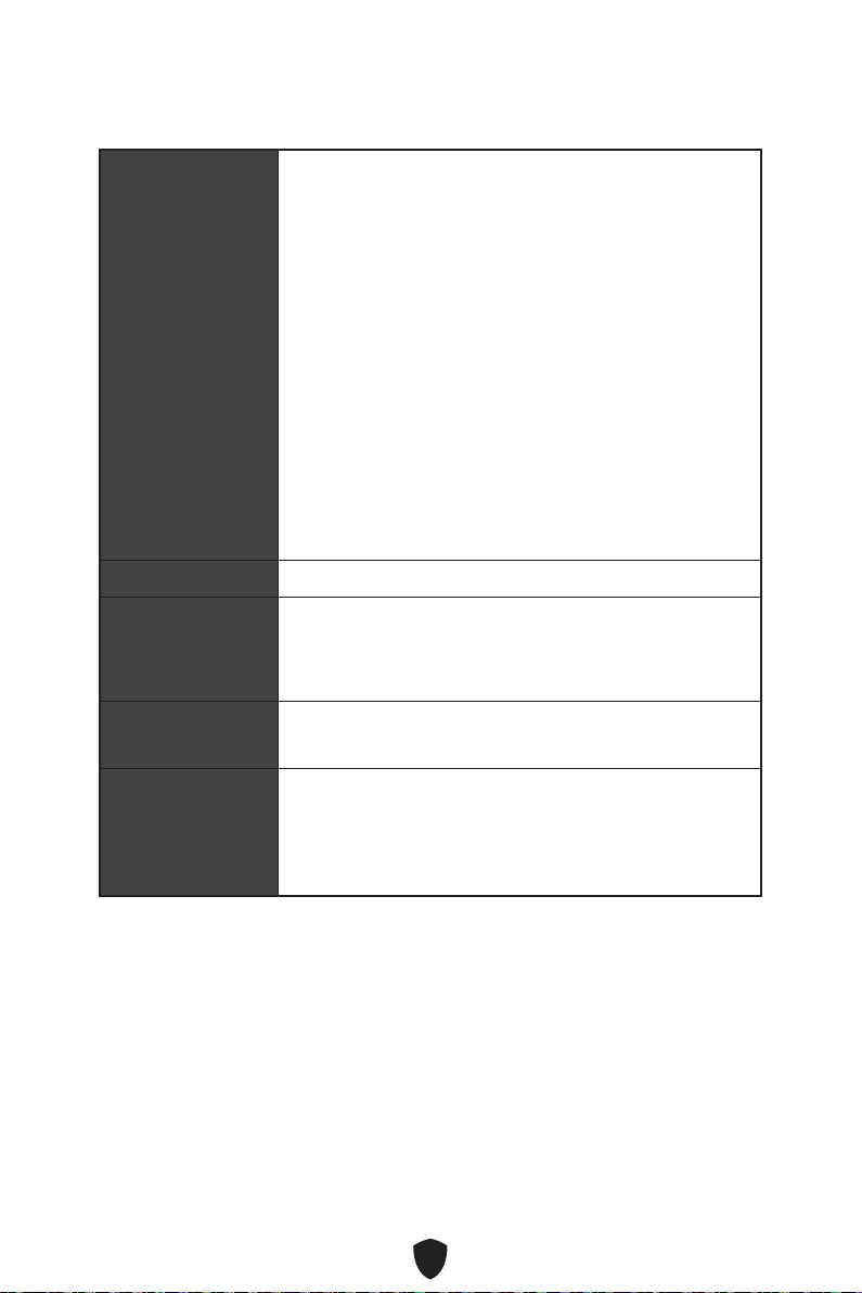
18
ASM3242)
UEFI AMI BIOS
ACPI 6.4, SMBIOS 3.5

19
MSI Center
Norton 360 Deluxe
Tile

20
MSI Center
•
•
•
•
•
•
•
• True Color
• Live Update
•
•
•
•
• MSI Companion
•
•
•
•
•
•
•
•
•
•
•
•
•
DIY Friendly
•
•
•
•
•
•
•
•
•
•
•
•
•
BIOS
•

21
•
•
•
•
•
•
•
•
•
•
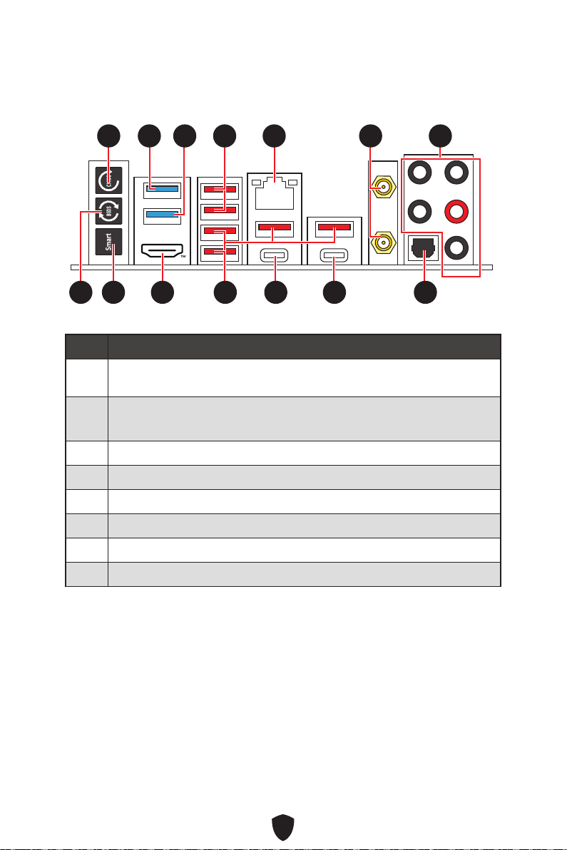
22
1
2
3
4
5
6
7
8
11 77
88 101099 14141313
55 66
12121111
3322 44

23
9
10
11
12
13
14

24
Mbps
AUDIO INPUT
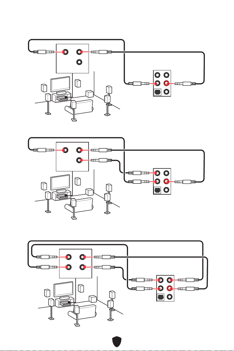
25
AUDIO INPUT
Rear Front
Center/
Subwoofer
AUDIO INPUT
Rear Front
Center/
Subwoofer
AUDIO INPUT
Rear Front
Side Center/
Subwoofer

26
1.
2.
11
22
3.

27
CPU_FAN1
PUMP_FAN1
SYS_FAN5
SYS_FAN4
JARGB_V2_2
ATX_PWR1
JUSB4
JUSB3
CPU_PWR1
CPU_PWR2
DIMMA2
DIMMB1
DIMMB2
DIMMA1
JCI1
JFP1
JBAT1
JOCFS1
LED_SW1
SYS_FAN3
SYS_FAN2
SYS_FAN1
JDASH1
JPWRLED1
JTBT1
JARGB_V2_1
JRGB1
JAUD1
JUSB2
JUSB1
M2_5
M2_1
M2_2
M2_3
M2_4
PCI_E1
PCI_E2
PCI_E3
JFP2
JTPM1
28

29
DIMMA1 DIMMB1
DIMMA2 DIMMB2
DIMMA2
DRAM Frequency
DIMMA2 DIMMA2
DIMMB2
DIMMA1
DIMMA2
DIMMB1
DIMMB2
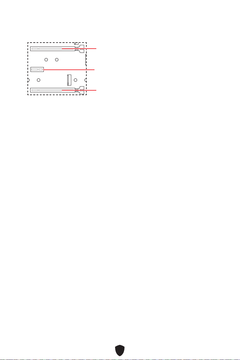
30
PCI_E1
PCI_E2
PCI_E3
PCI_E1
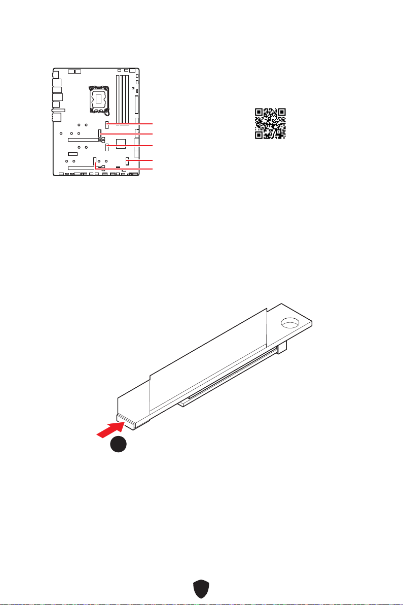
31
M2_1
M2_2
M2_4
M2_5
M2_3
1.
11
https://v.youku.com/v_show/
id_XNTg5NjQxOTcyNA==.html
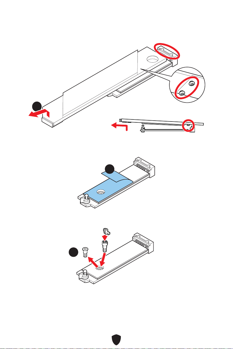
32
2.
22
3.
33
4.
44

33
5.
6.
30º30º
30º30º
66
66
55
55
7.
8.
9.
99
88
77

34
1.
11
11
2.
22
3.
33
33

35
4.
5.
30º30º
30º30º
44
44
55
55
6.
7.
66
77
77
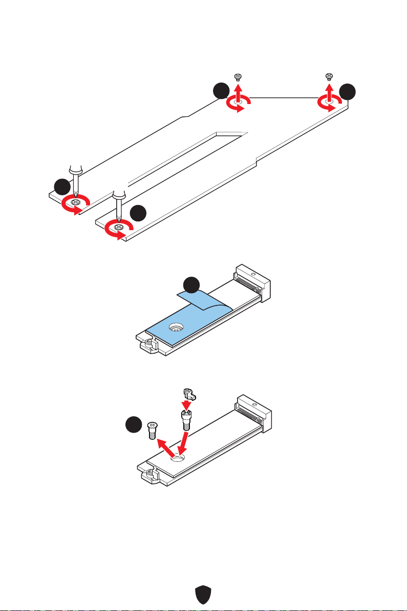
36
1.
11
11
11
11
2.
22
3.
33
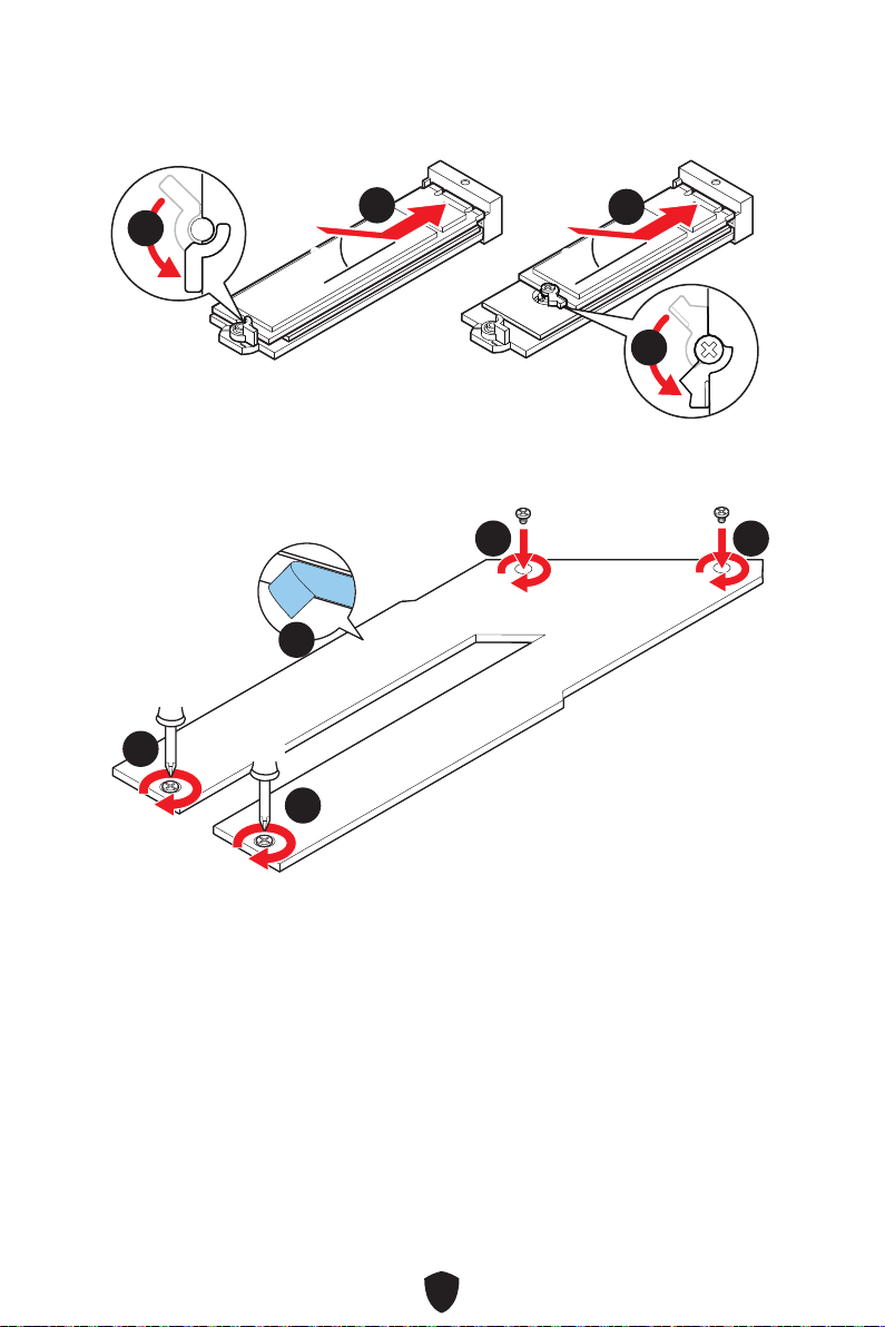
37
4.
5.
30º30º
30º30º
55
44
44
55
6.
7.
66
77
77 77
77
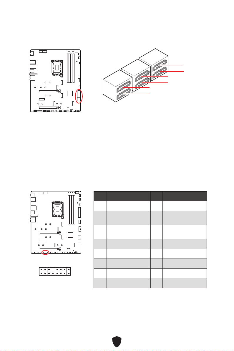
38
SATA5
SATA7
SATA_A1
SATA6
SATA8
SATA_A2
1
2 16
15
1 TBT_FORCE_PWR 2 TBT_S0IX_ENTRY_REQ
3
TBT_CIO_PLUG_
EVENT#
4 TBT_S0IX_ENTRY_ACK
5 SLP_S3#_TBT 6
TBT_PSON_
OVERRIDE_N
7 SLP_S5#_TBT 8 No Pin
9 Ground 10 SMBCLK_VSB
11 DG_PEWAKE# 12 SMBDATA_VSB
13 TBT_RTD3_PWR_EN 14 Ground
15 TBT_CARD_DET_R# 16 PD_IRQ#

39
1
2 10
9
1 MIC L 2 Ground
3 MIC R 4 NC
5 Head Phone R 6 MIC Detection
7 SENSE_SEND 8 No Pin
9 Head Phone L 10 Head Phone Detection
1
2 10
9
Power LED
Reserved
Power Switch
JFP1
Reset SwitchHDD LED
1
JFP2
Buzzer
Speaker

40
CPU_PWR1~2
1 Ground 2 Ground
3 Ground 4 Ground
5 +12V 6 +12V
7 +12V 8 +12V
ATX_PWR1
1 +3.3V 2 +3.3V
3 Ground 4 +5V
5 Ground 6 +5V
7 Ground 8 PWR OK
9 5VSB 10 +12V
11 +12V 12 +3.3V
13 +3.3V 14 -12V
15 Ground 16 PS-ON#
17 Ground 18 Ground
19 Ground 20 Res
21 +5V 22 +5V
23 +5V 24 Ground
5
4 1
8
CPU_PWR1~2
24
131
12
ATX_PWR1
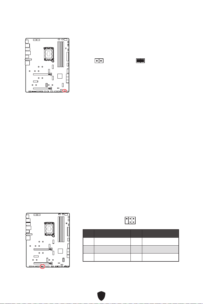
41
1. JCI1
2.
3. BIOS > SETTINGS > Security > Chassis Intrusion Configuration
4. Chassis IntrusionEnabled
5. F10EnterYes
6.
1. BIOS > SETTINGS > Security > Chassis Intrusion Configuration
2. Chassis IntrusionReset
3. F10EnterYes
1 No Pin 2 NC
3
MCU_SMB_SCL_M
4 MCU_SMB_SDA_M
5 VCC5 6 Ground
1
2
5
6
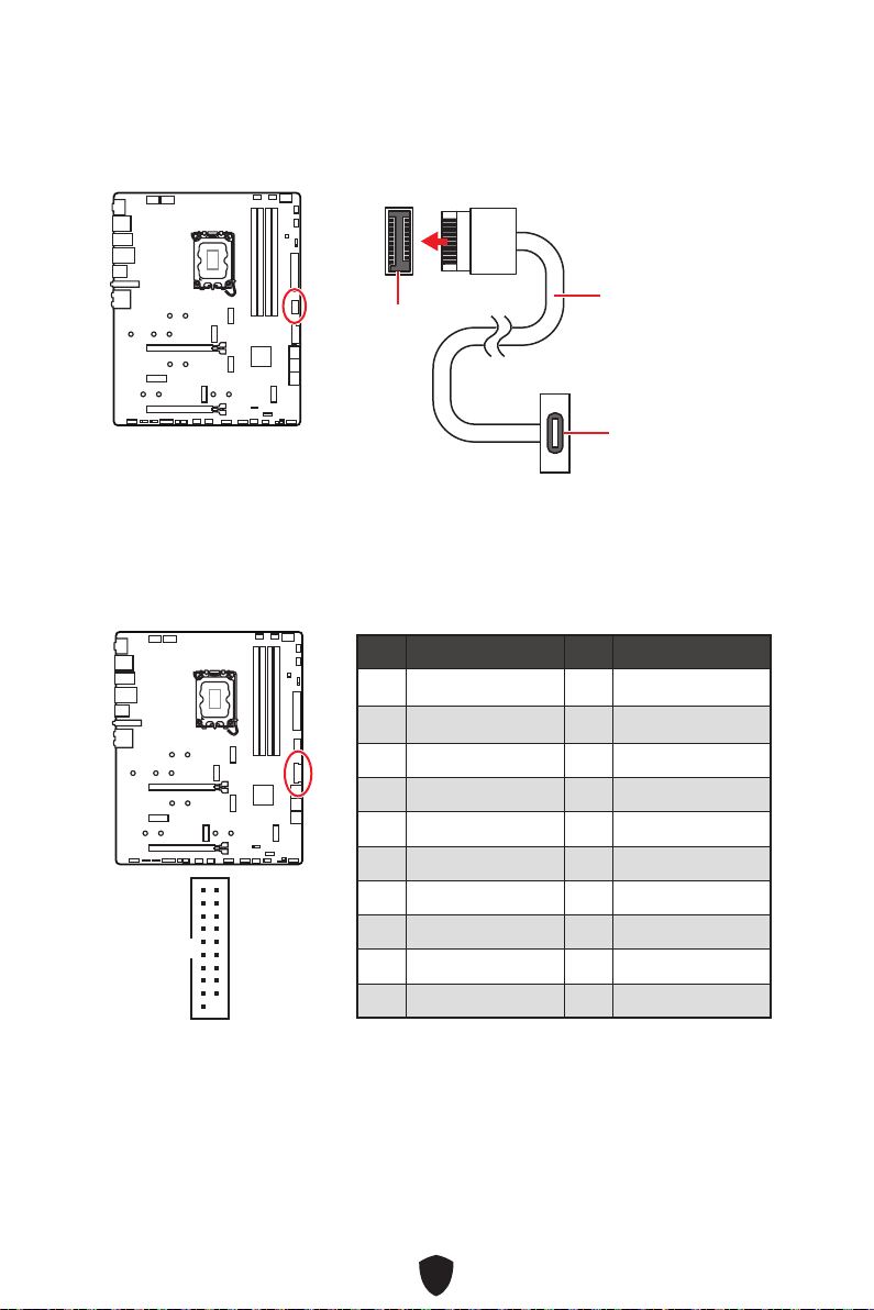
42
JUSB4
1 Power 2 USB3_RX_DN
3 USB3_RX_DP 4 Ground
5 USB3_TX_C_DN 6 USB3_TX_C_DP
7 Ground 8 USB2.0-
9 USB2.0+ 10 Ground
11 USB2.0+ 12 USB2.0-
13 Ground 14 USB3_TX_C_DP
15 USB3_TX_C_DN 16 Ground
17 USB3_RX_DP 18 USB3_RX_DN
19 Power 20 No Pin
1
10 11
20
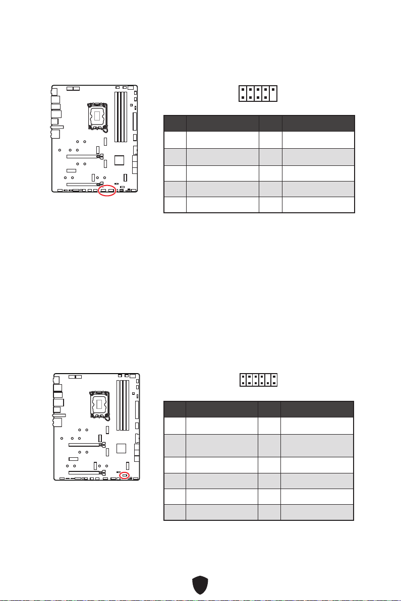
43
1 VCC 2 VCC
3 USB0- 4 USB1-
5 USB0+ 6 USB1+
7 Ground 8 Ground
9 No Pin 10 NC
1
2 10
9
1 SPI Power 2 SPI Chip Select
3
Master In Slave Out
(SPI Data)
4
Master Out Slave In
(SPI Data)
5 Reserved 6 SPI Clock
7 Ground 8 SPI Reset
9 Reserved 10 No Pin
11 Reserved 12 Interrupt Request
1
2 12
11
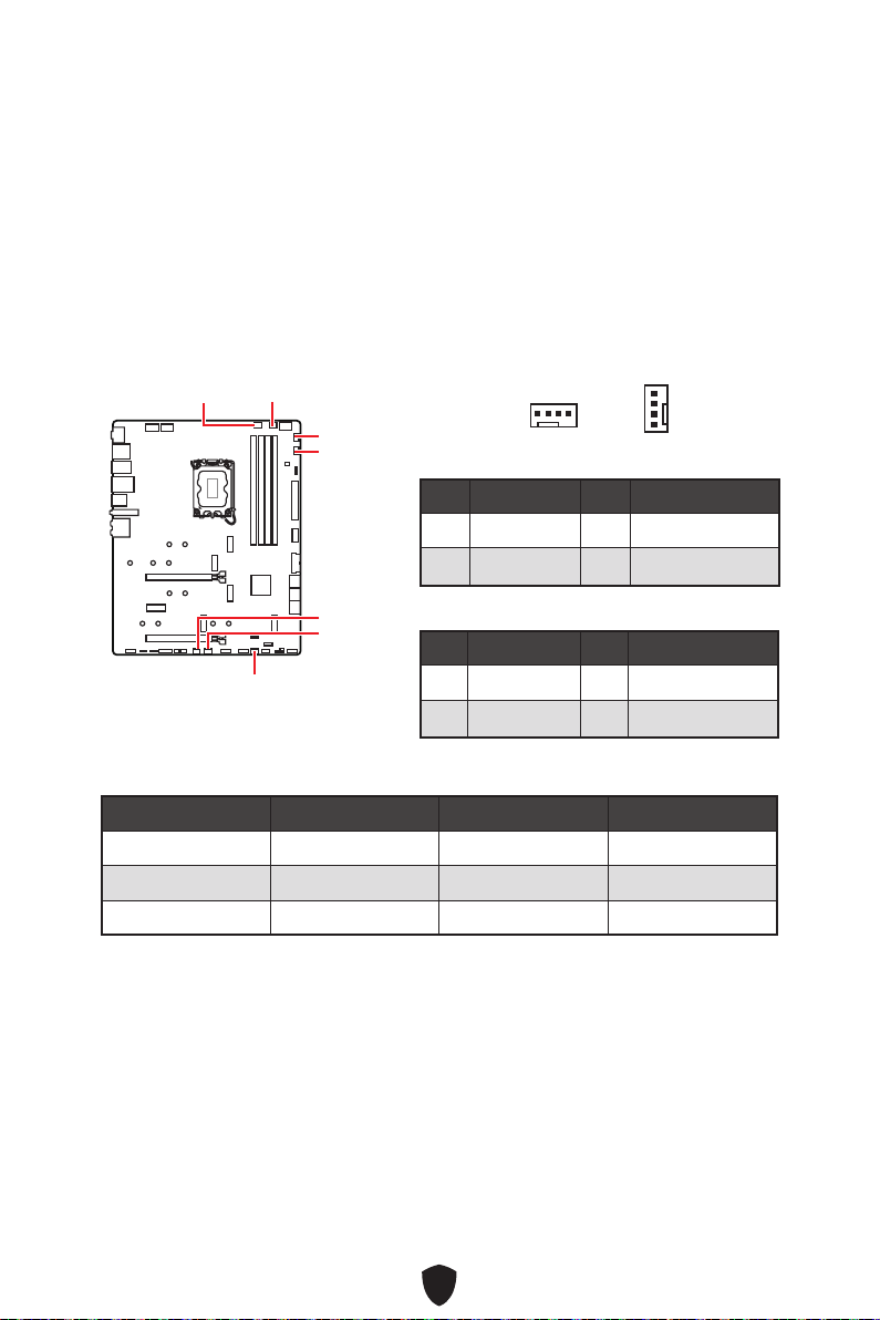
44
BIOS> HARDWARE MONITOR
Smart Fan Mode
Smart Fan Mode
CPU_FAN1
SYS_FAN2
SYS_FAN1
SYS_FAN3
PUMP_FAN1
SYS_FAN5
SYS_FAN4
1 Ground 2 +12V
3 Sense 4 Speed Control Signal
1 Ground 2 Voltage Control
3 Sense 4 NC
CPU_FAN1 2A 24W
PUMP_FAN1 3A 36W
SYS_FAN1~5 1A 12W
1
1
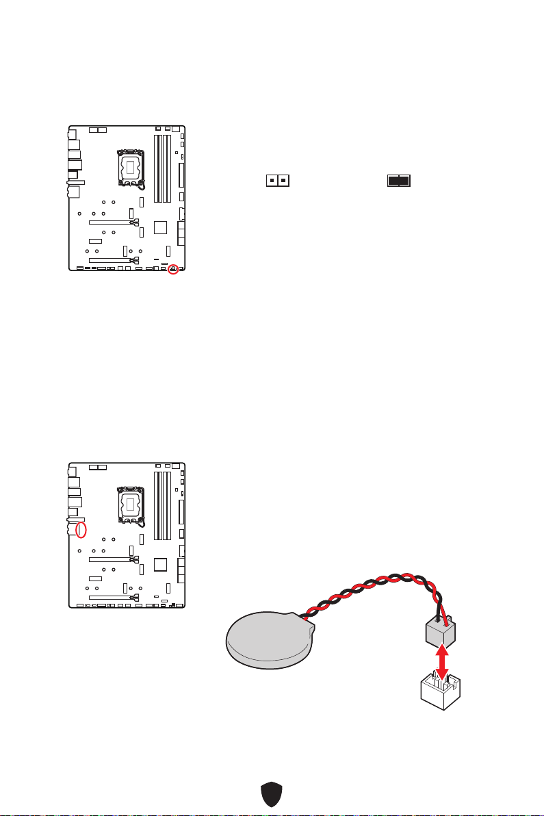
45
1.
2. JBAT1
3. JBAT1
4.
1.
2.
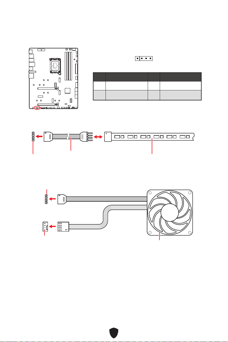
46
1
G
R
B
1
1
G
R
B
1 +12V 2 G
3 R 4 B
1
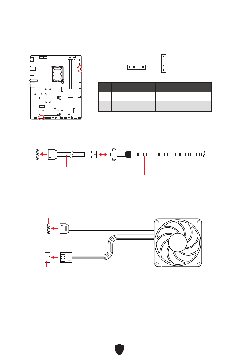
47
1 +5V 2 Data
3 No Pin 4 Ground
1
1
1
1
1
D
+5V
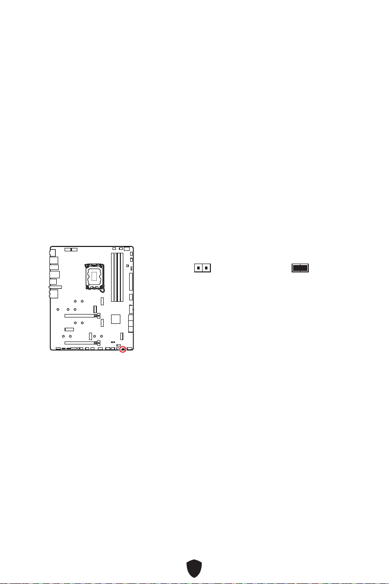
48

49
CPU
DRAM
VGA
BOOT
LED_SW1
LED_OFF
LED_ON
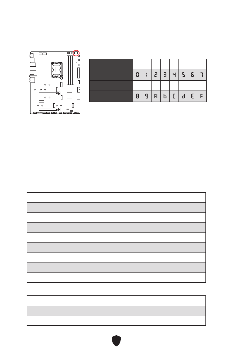
50
01
02
03
04
06
07
08
09
0B
0C - 0D
0E
0F
0 1 2 3 4 5 6 7
8 9 A B C D E F
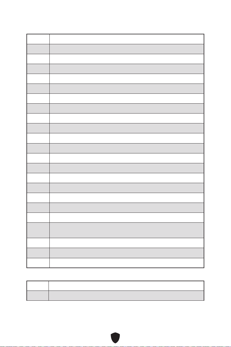
51
10
11
12 - 14
15
16 - 18
19
1A - 1C
2B
2C
2D
2E
2F
31
32
33
34
35
36
37
38 - 3A
3B
3C - 3E
4F
50
51

52
52
53
54
55
56
57
58
59
5A
5B
5C - 5F
60
61
62
63
64 - 67
68
69
6A
6B - 6F
70
71
72
73 - 77
78
79
7A - 7F

53
90
91
92
93
94
95
96
97
98
99
9A
9B
9C
9D
9E -9F
A0
A1
A2
A3
A4
A5
A6
A7
A8
A9
AB
AD
AE
AF

54
B0
B1
B2
B3
B4
B5
B6
B7
B8 - BF
D0
D1
D2
D3
D4
D5
D6
D7
D8
D9
DA
DB
DC
E0
E1
E2
E3

55
E4 - E7
E8
E9
EA
EB
EC - EF
F0
F1
F2
F3
F4
F5 - F7
F8
F9
FA
FB - FF
01
02
03
04
05
10
20

56
30
40
AC
AA
00 - 99

57
1.
2.
3. Restart
4. F11
5.
6. Press any key to boot from CD or DVD...
7.

58
1.
2.
3.
4.

59
5.
6.

60
1.
2.
3. Disc Image file
4. DVDSetup
5. Drivers/Software
6. Install
7.
8. OK
9.
MSI Center

61
UEFI BIOS
There is no GOP (Graphics Output protocol) support detected in this graphics
card
1.
2. Press DEL key to enter Setup Menu, F11 to enter
Boot MenuDelete
3. BIOS
UEFI

62
Press DEL key to enter Setup Menu, F11 to enter Boot
MenuDelete
F1:
F2:
F3:
F4:
F5:
F6:
F7:
F8:
F9:
F10:
F12:
Ctrl+F:
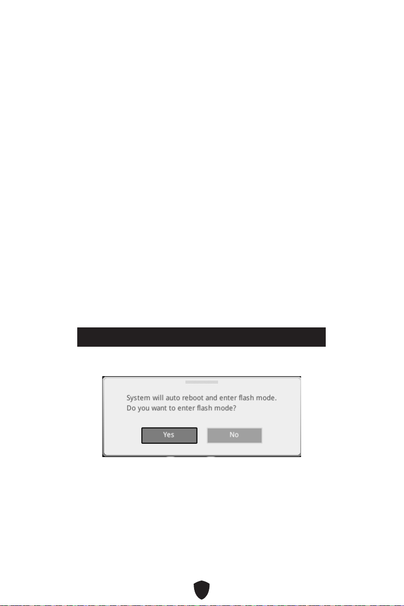
63
F6
1.
2.
3.
• Ctrl + F5
Press <Ctrl+F5> to activate M-Flash for BIOS update.
• DelM-FLASH
4.
5. Yes
6.

64
1. Support
2. Live UpdateAdvanced
3. Install
4.
5.
6.
1.
2.
3. CPU_PWR1 ATX_PWR1
4.
5.
6.
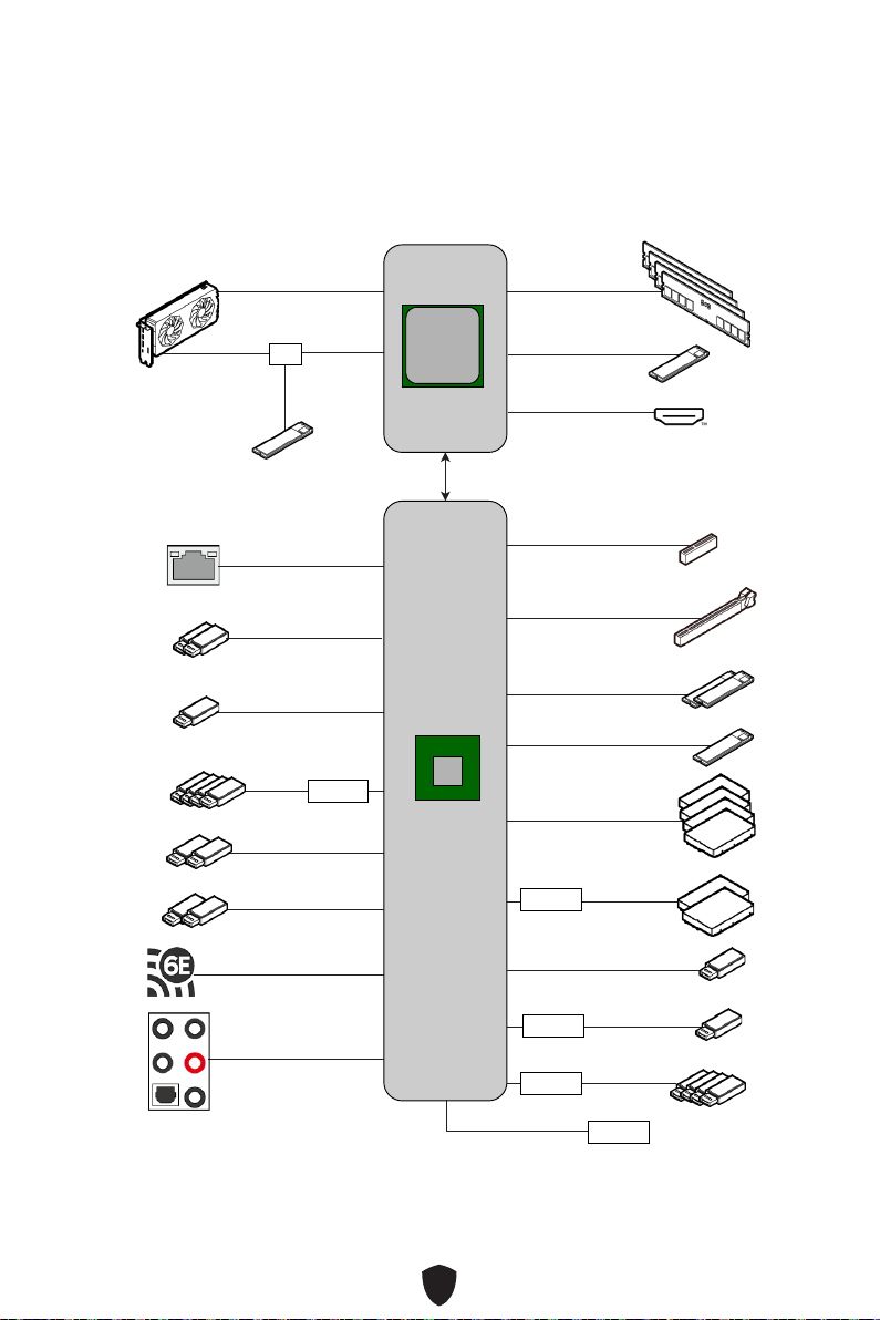
i
Block Diagram
MPG Z790 CARBON WIFI
PCI_E1
PCIe 5.0x16
DDR5
DIMM A1/A2
DIMM B1/B2
GEN4 x4 M.2_1
(PCIe Only)
GEN4 x4 M.2_3/ M.2_4
(PCIe Only)
USB3.2 Gen2x2 20Gbps
(Type-C)
USB3.2 Gen2 10Gbps
(Type-A)
Intel 2.5Gbps
SATA_5_6_7_8
SATA_A1_A2
ASM1061
WiFi 6E
PCH
HD Audio
ALC4080
CPU
DMI x8
PCIe 5.0 X8
PCIe 5.0 X8
GEN5 x4 M.2_2
(PCIe Only)
MUX
GEN4 x4 M.2_5
(PCIe + SATA)
ASM3242
USB3.2 Gen1 5Gbps
(Type-A)
GL3590
USB3.2 Gen2 10Gbps
(Type-A)
USB3.2 Gen2 10Gbps
(Type-C)
GL850
USB2.0
(Front Type-A)
USB3.2 Gen2x2 20Gbps
(Front Type-C)
USB3.2 Gen1 5Gbps
(Front Type-A)
PCI_E2
PCIe 3.0x 1
PCI_E3
PCIe 4.0x 4
SPI
HDMI™ 2.1
(4K@60Hz)

ii
Regulatory Notices
FCC-B Radio Frequency Interference Statement
This equipment has been tested and found to comply with the limits
for a Class B digital device, pursuant to part 15 of the FCC rules. These
limits are designed to provide reasonable protection against harmful
interference in a residential installation. This equipment generates,
uses and radiates radio frequency energy, and, if not installed and
used in accordance with the instructions, may cause harmful interference to radio
communications. However, there is no guarantee that interference will not occur in a
particular installation. If this equipment does cause harmful interference to radio or
television reception, which can be determined by turning the equipment off and on, the
user is encouraged to try to correct the interference by one or more of the following
measures:
Reorient or relocate the receiving antenna.
Increase the separation between the equipment and receiver.
Connect the equipment into an outlet on a circuit different from that to which the
receiver is connected.
NOTE
The changes or modifications not expressly approved by the party responsible for
compliance could void the user’s authority to operate the equipment.
Shield interface cables and AC power cord, if any, must be used in order to comply
with the emission limits.
FCC Conditions
This device complies with part 15 of the FCC Rules. Operation is subject to the
following two conditions:
This device may not cause harmful interference.
This device must accept any interference received, including interference that may
cause undesired operation.
MSI Computer Corp.
901 Canada Court, City of Industry, CA 91748, USA
(626)913-0828
www.msi.com

iii
CE Conformity
Products bearing the CE marking comply with one or more of the
following EU Directives as may be applicable:
RED 2014/53/EU
Low Voltage Directive 2014/35/EU
EMC Directive 2014/30/EU
RoHS Directive 2011/65/EU
ErP Directive 2009/125/EC
Compliance with these directives is assessed using applicable European Harmonized
Standards.
The point of contact for regulatory matters is MSI-Europe: Eindhoven 5706 5692 ER
Son.
Products with Radio Functionality (EMF)
This product incorporates a radio transmitting and receiving device. For computers
in normal use, a separation distance of 20 cm ensures that radio frequency exposure
levels comply with EU requirements. Products designed to be operated at closer
proximities, such as tablet computers, comply with applicable EU requirements in
typical operating positions. Products can be operated without maintaining a separation
distance unless otherwise indicated in instructions specific to the product.
Restrictions for Products with Radio Functionality
CAUTION: IEEE 802.11x wireless LAN with 5.15~5.35 GHz frequency
band is restricted for indoor use only in all European Union member
states, EFTA (Iceland, Norway, Liechtenstein), and most other European
countries (e.g., Switzerland, Turkey, Republic of Serbia). Using this WLAN
application outdoors might lead to interference issues with existing radio
services.
Radio frequency bands and maximum power levels
Features: Wi-Fi 6E, BT
Frequency Range: 2.4 GHz: 2400~2485MHz; 5 GHz: 5150~5350MHz,
5470~5725MHz, 5725~5850MHz; 6 GHz: 5955~6415MHz
Max Power Level: 2.4 GHz: 20dBm; 5 GHz: 23dBm; 6 GHz: 23dBm

iv
Wireless Radio Use
This device is restricted to indoor use when operating in the 2.4GHz, 5GHz, 6GHz
frequency band.
Cet appareil doit être utilisé à l’intérieur.
Compliance Statement of Innovation, Science and
Economic Development Canada (ISED)
This device complies with with Innovation, Science and Economic Development
Canada’s licence-exempt RSS(s). Operation is subject to the following two conditions:
(1) this device may not cause interference, and (2) this device must accept any
interference, including interference that may cause undesired operation of the device.
Operation in the band 5150-5250 MHz is only for indoor use to reduce the potential for
harmful interference to co-channel mobile satellite systems.
CAN ICES-003(B)/NMB-003(B)
Australia and New Zealand notice
This equipment incorporates a radio transmitting and receiving device. In normal use,
a separation distance of 20 cm ensures that radio frequency exposure levels comply
with the Australian and New Zealand Standards.
VCCI-B
R-R-MSI-10-7D89
v
Battery Information
European Union:
Batteries, battery packs, and accumulators should not be disposed of as
unsorted household waste. Please use the public collection system to
return, recycle, or treat them in compliance with the local regulations.
BSMI:
For better environmental protection, waste batteries should be collected
separately for recycling or special disposal.
California, USA:
The button cell battery may contain perchlorate material and requires
special handling when recycled or disposed of in California.
For further information please visit:
http://www.dtsc.ca.gov/hazardouswaste/perchlorate/
CAUTION: There is a risk of explosion, if battery is incorrectly replaced. Replace only
with the same or equivalent type recommended by the manufacturer.
Chemical Substances Information
In compliance with chemical substances regulations, such as the EU REACH
Regulation (Regulation EC No. 1907/2006 of the European Parliament and the
Council), MSI provides the information of chemical substances in products at:
https://csr.msi.com/global/index
Environmental Policy
The product has been designed to enable proper reuse of parts and
recycling and should not be thrown away at its end of life.
Users should contact the local authorized point of collection for recycling
and disposing of their end-of-life products.
Visit the MSI website and locate a nearby distributor for further recycling
information.
Users may also reach us at [email protected] for information regarding proper
Disposal, Take-back, Recycling, and Disassembly of MSI products.
WEEE (Waste Electrical and Electronic Equipment)
Statement
ENGLISH
To protect the global environment and as an environmentalist, MSI must
remind you that...
Under the European Union (“EU”) Directive on Waste Electrical and
Electronic Equipment, Directive 2002/96/EC, which takes effect on August
13, 2005, products of “electrical and electronic equipment” cannot be

vi
discarded as municipal wastes anymore, and manufacturers of covered electronic
equipment will be obligated to take back such products at the end of their useful life.
MSI will comply with the product take back requirements at the end of life of MSI-
branded products that are sold into the EU. You can return these products to local
collection points.
DEUTSCH
Hinweis von MSI zur Erhaltung und Schutz unserer Umwelt
Gemäß der Richtlinie 2002/96/EG über Elektro- und Elektronik-Altgeräte dürfen
Elektro- und Elektronik-Altgeräte nicht mehr als kommunale Abfälle entsorgt
werden. MSI hat europaweit verschiedene Sammel- und Recyclingunternehmen
beauftragt, die in die Europäische Union in Verkehr gebrachten Produkte, am Ende
seines Lebenszyklus zurückzunehmen. Bitte entsorgen Sie dieses Produkt zum
gegebenen Zeitpunkt ausschliesslich an einer lokalen Altgerätesammelstelle in Ihrer
Nähe.
FRANÇAIS
En tant qu’écologiste et afin de protéger l’environnement, MSI tient à rappeler ceci...
Au sujet de la directive européenne (EU) relative aux déchets des équipement
électriques et électroniques, directive 2002/96/EC, prenant effet le 13 août 2005,
que les produits électriques et électroniques ne peuvent être déposés dans les
décharges ou tout simplement mis à la poubelle. Les fabricants de ces équipements
seront obligés de récupérer certains produits en fin de vie. MSI prendra en compte
cette exigence relative au retour des produits en fin de vie au sein de la communauté
européenne. Par conséquent vous pouvez retourner localement ces matériels dans
les points de collecte.
ESPAÑOL
MSI como empresa comprometida con la protección del medio ambiente, recomienda:
Bajo la directiva 2002/96/EC de la Unión Europea en materia de desechos y/o
equipos electrónicos, con fecha de rigor desde el 13 de agosto de 2005, los productos
clasificados como “eléctricos y equipos electrónicos” no pueden ser depositados en
los contenedores habituales de su municipio, los fabricantes de equipos electrónicos,
están obligados a hacerse cargo de dichos productos al termino de su período de vida.
MSI estará comprometido con los términos de recogida de sus productos vendidos en

vii
la Unión Europea al final de su periodo de vida. Usted debe depositar estos productos
en el punto limpio establecido por el ayuntamiento de su localidad o entregar a una
empresa autorizada para la recogida de estos residuos.
NEDERLANDS
Om het milieu te beschermen, wil MSI u eraan herinneren dat….
De richtlijn van de Europese Unie (EU) met betrekking tot Vervuiling van Electrische
en Electronische producten (2002/96/EC), die op 13 Augustus 2005 in zal gaan kunnen
niet meer beschouwd worden als vervuiling. Fabrikanten van dit soort producten
worden verplicht om producten retour te nemen aan het eind van hun levenscyclus.
MSI zal overeenkomstig de richtlijn handelen voor de producten die de merknaam MSI
dragen en verkocht zijn in de EU. Deze goederen kunnen geretourneerd worden op
lokale inzamelingspunten.
SRPSKI
sredini, MSI mora da vas podesti da…
Direktiva 2002/96/EC, koja stupa na snagu od 13. Avgusta 2005, proizvodi koji spadaju
kojima je istekao vek trajanja, koji imaju MSI oznaku i koji su prodati u EU. Ove
POLSKI
produktów elektrycznych i elektronicznych (Dyrektywa 2002/96/EC), która wchodzi w
wyznaczonych punktach zbiorczych.
TÜRKÇE
2002/96/EC platné od 13. srpna 2005 je zakázáno likvidovat “elektrické a elektronické

viii
MAGYAR
az MSI emlékezteti Önt, hogy ...
elektronikus berendezések hulladékairól szóló 2002/96/EK irányelve szerint az
hulladékként, és az ilyen elektronikus berendezések gyártói kötelessé válnak az
ilyen termékek visszavételére azok hasznos élettartama végén. Az MSI betartja
a termékvisszavétellel kapcsolatos követelményeket az MSI márkanév alatt az
EU-n belül értékesített termékek esetében, azok élettartamának végén. Az ilyen
ITALIANO
Per proteggere l’ambiente, MSI, da sempre amica della natura, ti ricorda che….
In base alla Direttiva dell’Unione Europea (EU) sullo Smaltimento dei Materiali
Elettrici ed Elettronici, Direttiva 2002/96/EC in vigore dal 13 Agosto 2005, prodotti
appartenenti alla categoria dei Materiali Elettrici ed Elettronici non possono più
essere eliminati come rifiuti municipali: i produttori di detti materiali saranno obbligati
a ritirare ogni prodotto alla fine del suo ciclo di vita. MSI si adeguerà a tale Direttiva
ritirando tutti i prodotti marchiati MSI che sono stati venduti all’interno dell’Unione
Europea alla fine del loro ciclo di vita. È possibile portare i prodotti nel più vicino punto
di raccolta
https://csr.msi.com/tw/Japan-JIS-C-0950-Material-Declarations
India RoHS
This product complies with the “India E-waste (Management and Handling) Rule 2011”
and prohibits use of lead, mercury, hexavalent chromium, polybrominated biphenyls
or polybrominated diphenyl ethers in concentrations exceeding 0.1 weight % and 0.01
weight % for cadmium, except for the exemptions set in Schedule 2 of the Rule.
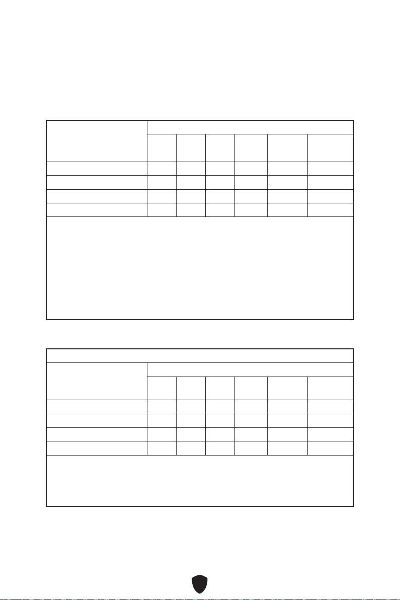
ix
(Pb)
(Hg)
(Cd)
(Cr(VI))
(PBB)
(PBDE)
(Pb)
(Hg)
(Cd)
(Cr
+6
)
(PBB)
(PBDE)
x
Copyright and Trademarks Notice
Copyright © Micro-Star Int’l Co., Ltd. All rights reserved. The MSI
logo used is a registered trademark of Micro-Star Int’l Co., Ltd. All
other marks and names mentioned may be trademarks of their respective owners. No
warranty as to accuracy or completeness is expressed or implied. MSI reserves the
right to make changes to this document without prior notice.
Technical Support
If a problem arises with your system and no solution can be obtained from the user
guide, please contact your place of purchase or local distributor. Alternatively, please
try the following help resources for further guidance.
Visit the MSI website for technical guide, BIOS updates, driver updates, and other
information: http://www.msi.com
Register your product at: http://register.msi.com
Revision History
Version 1.0, 2022/10, First release.