Loading ...
Loading ...
Loading ...
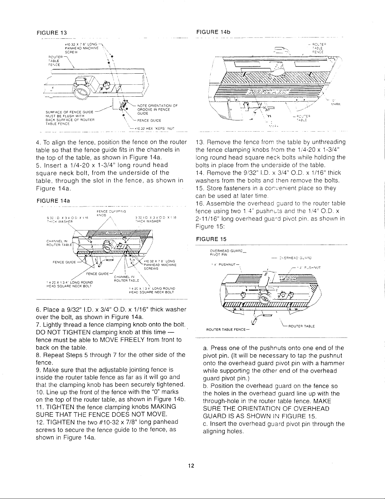
FIGURE 13
\,/
NOTE ORIENTATION OF
,O GROOVE IN FENCE
SURFACE OF FENCE GUfDE " \, GUIDE
MUST BE FLUSH WITH _ \_
BACK SURFACE OF ROUTER ' '_ FENCE GUIDE
TABLE FENCE
_'10 32 HEX 'KEPS NUT
FIGURE 14b
-- RCLTE q
--- "P:i / FENCE
4. To align the fence, position the fence on the router
table so that the fence guide fits in the channels in
the top of the table, as shown in Figure 14a.
5. Insert a 1/4-20 x 1-3/4" long round head
square neck bolt, from the underside of the
table, through the slot in the fence, as shown in
Figure 14a.
FIGURE 14a
F El'ICE C L_ !,lPrNO
KNOB
9,32 :D X34OD Xll£ _321D X34OD Xt:6
TH!CK WASHER THICK WASHER
",, X
, \ '
E:U'DEJ 11" SCREWS
CHANNEL 154
4 20 X 13 4- LONG ROUND ROUTER TABLE '_\
HEAD SQUARE NECK BOLT
x
i 4 2c x t 3 4 LONG ROUND
HEAD SQUARE NECK BOLT
6. Place a 9/32" !.D. x 3/4" O.D. x 1/16" thick washer
over the bolt, as shown in Figure 14a.
7. Lightly thread a fence clamping knob onto the bolt.
DO NOT TIGHTEN clamping knob at this time --
fence must be able to MOVE FREELY from front to
back on the table.
8. Repeat Steps 5 through 7 for the other side of the
fence.
9. Make sure that the adjustable jointing fence is
inside the router table fence as far as it will go and
that the clamping knob has been securely tightened•
10. Line up the front of the fence with the "0" marks
on the top of the router table, as shown in Figure 14b.
11. TIGHTEN the fence clamping knobs MAKING
SURE THAT THE FENCE DOES N©T MOVE.
12. TIGHTEN the two #10-32 x 7/8" long panhead
screws to secure the fence guide to the fence, as
shown in Figure 14a.
13. Remove the fence from the table by unthreading
the fence clamping knobs from the 1/4-20 x 1-3/4"
long round head square neck bolts while holding the
bolts in place from the underside of the table.
14. Remove the 9!32" I.D. x 3/4" O.D. x 1/16" thick
washers from the bolts and then remove the bolts.
15. Store fasteners in a cor:venient place so they
can be used at later time.
16. Assemble the overhead guard to the router table
fence using two 14" pushnLts and the 1/4" O,D. x
2-11/16" long overhead guard pivot pin, as shown in
Figure 15:
FIGURE 15
OVERHEAD GUARD
PP,IOT PIN
-- D'.ERHEAD GL'_=D
• 4 PUSHNUT--
t
l_ '_'_ ROUTER TABLE
ROUTER TABLE FENCE--
a. Press one of the pushnuts onto one end of the
pivot pin. (It will be necessary to tap the pushnut
onto the overhead guard pivot pin with a hammer
while supporting the other end of the overhead
guard pivot pin.)
b. Position the overhead guard on the fence so
the holes in the overhead guard line up with the
through-hole in the router table fence• MAKE
SURE THE ORIENTATION OF OVERHEAD
GUARD ISAS SHOWN IN FIGURE 15.
c. Insert the overhead guard pivot pin through the
aligning holes.
12
Loading ...
Loading ...
Loading ...