Loading ...
Loading ...
Loading ...
18.Checkthattheextenstonsareparallelandeven
with.orslightlybelow,the topof thetable.
19.[A }[,,_ WARNINGj In nocasearetheextensions
to be higherthan.orabove,thetopof thetabletop
orelsetheymayinterferewiththeworkpieceduring
routing.Thiscouldcausea conditionthatcanresult
in possibleseriousinjury.
20.Iftheextensionsarehigherand/ornotparallel.
thenloosenthefastenersholdingtheextensionsto
thebracesandto thetabietop.andrepositionthem
untiltheyare parallel.
2I. SECURELYTIGHTENALLFASTENERSAGAIN.
22.Todoublecheck,slidea flatpieceofwoodalong
topoftheroutertablein alldirections.Makesure
thattheedgeof thewoodmovesfreelywithoutcon-
tactingtheedgesofthe extensions.
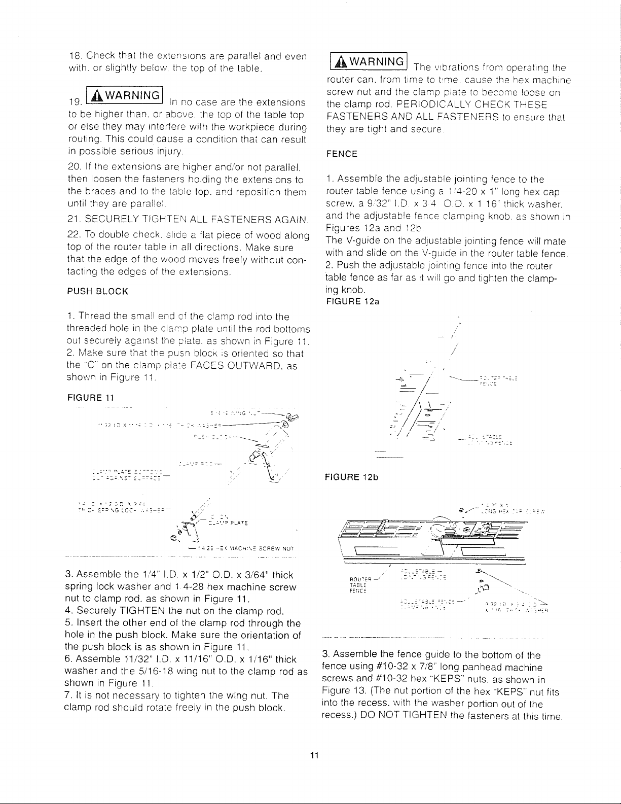
PUSHBLOCK
1.Threadthesmallendoftheclamprodintothe
threadedholein theclampplateuntiltherodbottoms
outsecurelyagainsttheplate,asshownin Figure11.
2. Makesurethatthepushblockis orientedso that
the'C ontheclampplateFACESOUTWARD,as
shownin Figure1t.
FIGURE 11
"'22!DX:'": 27 ' "'4 -- --< .'.a3--_-=__'_
2_-". '= -*':._.TE -2--2".'£ ,..
Z-- :_-" NST -:_:::EE
T_ C- _='_ ",G LQC* .'._-S-E:-- ,,,<,;
t4 2_. -E'( MACH:X-_- SCREW NUT
3. Assemble the 1,/4'. I.D. x 1/2" O.D. x 3/64" thick
spring lock washer and 1 4-28 hex machine screw
nut to clamp rod. as shown in Figure 11.
4. Securely TIGHTEN the nut on the clamp rod.
5. Insert the other end of the clamp rod through the
hole in the push block. Make sure the orientation of
the push block is as shown in Figure 11.
6. Assemble 11/32" I.D. x 11/16" O.D. x 1/16" thick
washer and the 5/16-18 wing nut to the clamp rod as
shown in Figure 11.
7. It is not necessary to tighten the wing nut. The
clamp rod should rotate freely in the push block.
{,_WARNING The v{brations from operating the
router can, from time to t_me. cause the hex machine
screw nut and the clamp plate to become loose on
the clamp rod. PERIODICALLY CHECK THESE
FASTENERS AND ALL FASTENERS to ensure that
they are tight and secure
FENCE
1. Assemble the adjustable jointing fence to the
router table fence using a 1'4-20 x 1" long hex cap
screw, a 9'32" I.D x 34 O.D. x 1 16" thick washer.
and the adjustab!e fence clamping knob. as shown in
Figures 12a and 12b
The V-guide on the adjustable jointing fence will mate
with and slide on the V-guide in the router table fence.
2. Push the adjustable jointing fence into the router
table fence as far as _twill go and tighten the clamp-
ing knob.
FIGURE 12a
/
/
'&_-7
a7. _-a_LE
FIGURE 12b
"z2CX:
', \ ,,' \ ,
/
_' _Z'.-'.S =£',7B o- _"_,ROU*_Eq
TABLE _
FEr;CE L >_
[-:'.'= ',G -',i-
' ' _B 7_ Z" .'.ZB"_ER
3, Assemble the fence guide to the bottom of the
fence using #10-32 x 7/8" long panhead machine
screws and #10-32 hex "KEPS" nuts. as shown in
Figure 13. (The nut portion of the hex "KEPS" nut fits
into the recess, with the washer portion out of the
recess.) DO NOT TIGHTEN the fasteners at this time.
11
Loading ...
Loading ...
Loading ...