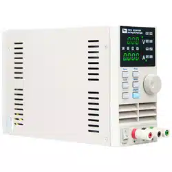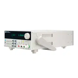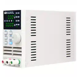
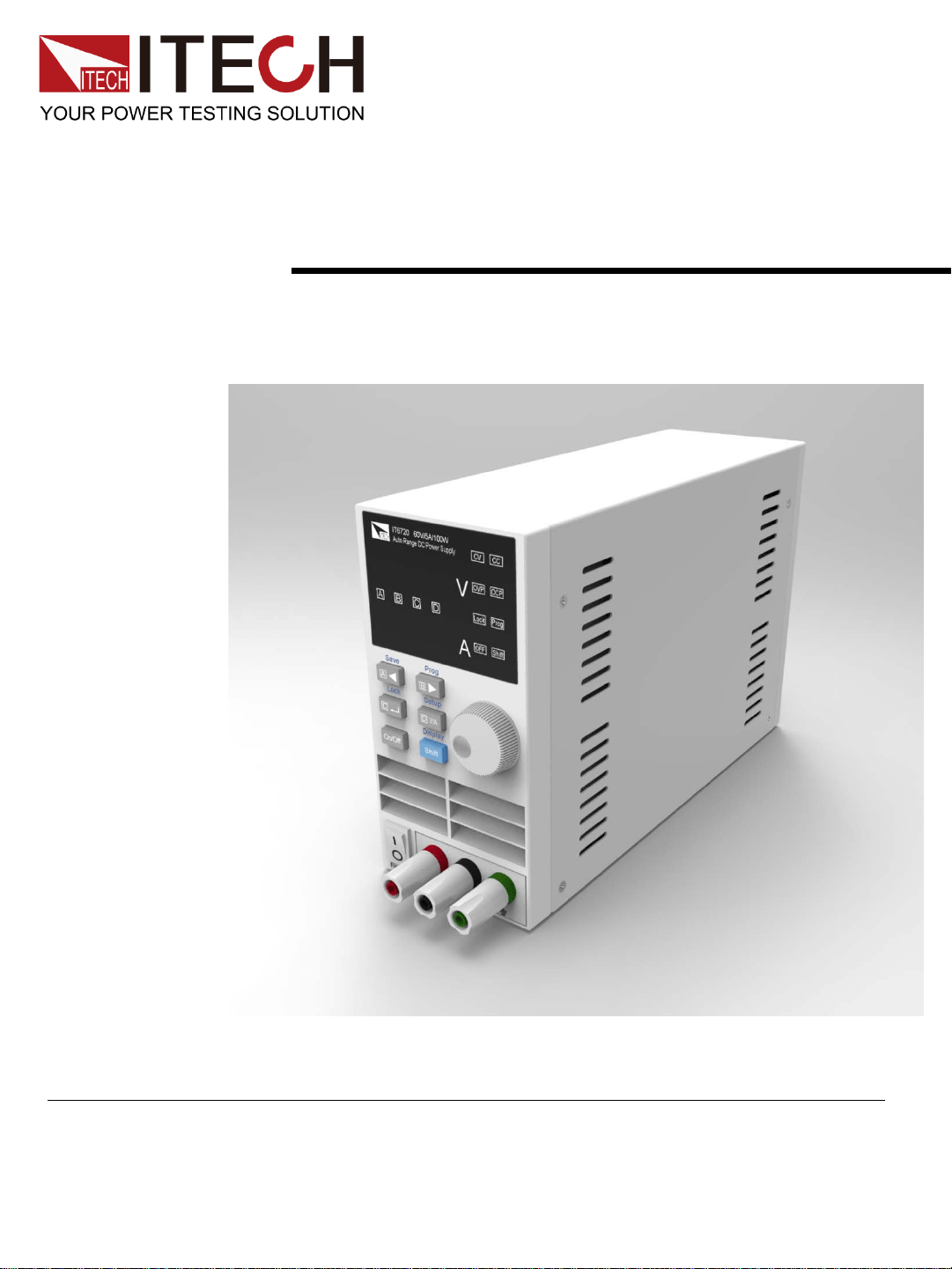
Digital Control Power Supply
User ’s Manual
IT6700
Models IT6720/IT6721
Copyright ©ITECH Electronic Co., Ltd.

Safety Regulations
To avoid electrical shock, do not open the cabinet. Refer servicing
to qualified personnel only.
To avoid injuries, always disconnect power, discharge circuits, and
remove external voltage sources before touching components.
KEEP AWAY FROM LIVE CIRCUITS.
We cannot accept responsibility for any direct or indirect financial
damage or loss of profit that might occur when using the power
supply.
The instrument chassis and cover must be connected to an
electrical ground.
WARNING
We certify that this product met its published specifications at
time of shipment from the factory.
Certification
Notice
The information contained in this document is subject to change
without notice.
Warranty
This hardware product is warranted against defects in material and
workmanship for a period of ONE year from date of delivery. IT6700
power supply for use with a hardware product and when properly
installed on that hardware product, are warranted not to fail to
execute their programming instructions due to defects in material
and workmanship for a period of 90 days from date of delivery.
During the warranty period our company will either repair or replace
products which prove to be defective. Our company does not
warranty that the operation for the software firmware or hardware
shall be uninterrupted or error free. For warranty service, with the
exception of warranty options, this product must be returned to a
service facility designated by our company. Customer shall prepay
shipping charges by (and shall pay all duty and taxes) for products
returned to our place for warranty service. Our company shall pay
for return of products to Customer.
Compliance Statements
The ITECH product you have purchased is subject to Directive
2002/96/EC of the European Parliament and the Council of the
European Union on waste electrical and electronic equipment
(WEEE) and, in jurisdictions adopting that Directive, is marked
as being put on the market after August 13, 2005, and should not
be disposed of as unsorted municipal waste. Please utilize your
local WEEE collection facilities in the disposition of this product
and otherwise observe all applicable requirements.
Disposal of Old Electrical & Electronic Equipment (Applicable in the
European Union and other European countries with separate collection
systems)
Connect it to safety earth ground using the wire recommended in
the user’s manual.
High voltage danger
The symbol on an instrument indicates that the user should refer
to the operating
instructions located in the manual.
Safety Symbols
The foregoing warranty shall not apply to defects resulting from improper
or inadequate maintenance by the customer, customer-supplied software or
interfacing, unauthorized
modification or misuse, operation outside of the environmental
specifications for the product, or improper site preparation and
maintenance.
Limitation of Warranty
About IT6700
With widest voltage and current range, IT6700 digital DC power
supplies are applied in many fields.
Take IT6720 for example, with max power 100W and output
adjustable in 60V/5A, auto control voltage/current slew rate, power
rate up to three times rapid than other similar products, a unit can
replace three models (60V*1.6A/ 32V*3A/ 20V*5A), reduce your
repeat investment.
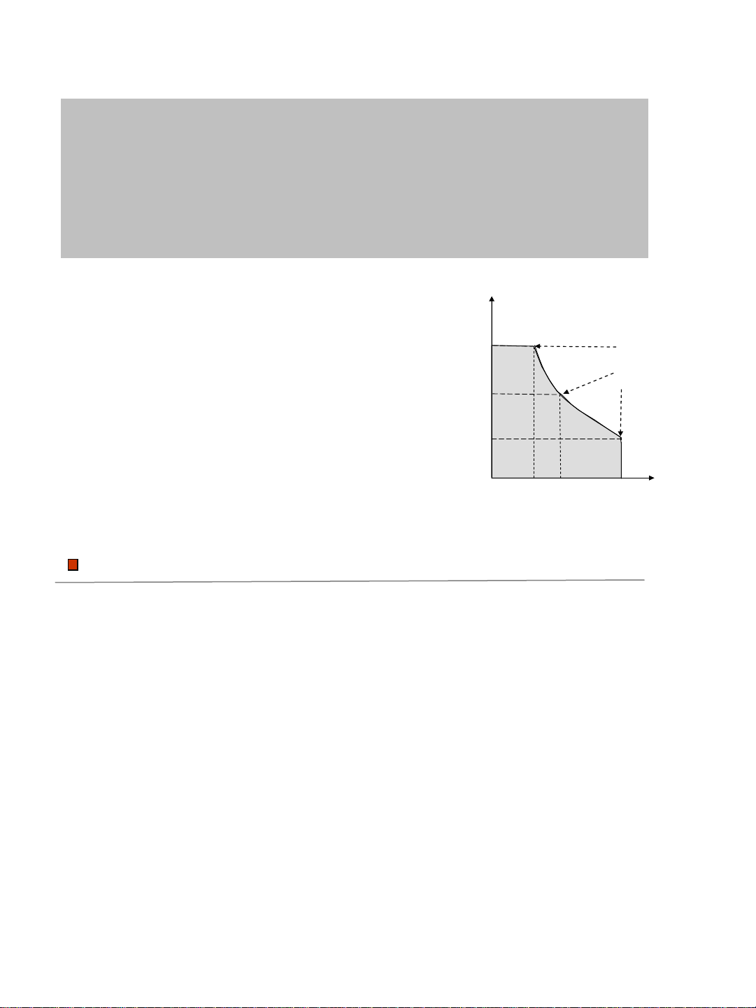
IT6720 output curve
1
2 3 4 5
20
40
60
I
V
Power
100%
When you set the output voltage as 60V,
because the max power of IT6720 is 100W,
so the max output current is 100W/60V=1.6A.
When you change the output voltage to 30V,
the output current is 100W/30V=3.2A.
Calculate according to the above way when
the output voltage is 20V, the output current
should be 5A, but as the max rating current
of IT6720 is 8A, so the final max output
current is 5A.
Example:
Function
Fully digital control
High resolution 10mV/1mA in Full range
Low ripple and noise
Software calibration
Bright and easy to read display (VFD)
Constant current and constant voltage output
Selectable remote control keypads
High reliability OVP/OCP/OTP protection
Output on/off control
Best performance /price ratio
Storage for 4*100 preset voltage and current output
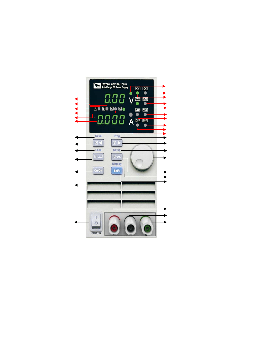
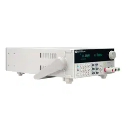
Panel Layout
Voltage / Current Selector + Memory D Button
Memory mode(Shift)
Current setup Indicator
Output +
Output
–
Ground
Rotary Encoder
Main Power ON/OFF
Output ON/OFF Button
Voltage Value
Current Value
Step A + Memory A
StepC + MemoryC
StepB + MemoryB
StepD + MemoryD
Output OFF Indicator
Shift Indicator
Keyboard Lock Indicator
Memory mode Indicator
OVP Indicator
OCP Indicator
CV mode Indicator
CC mode Indicator
Voltage setup Indicator
Left arrow + Memory A Button
Right arrow + Memory B Button
Enter + Memory C Button
Shift Button
Setup Display (Shift)
Function Setup (Shift)
Keyboard (Shift)
Memory save (Shift)
Air flow input
Quick Start
V
A
IT6720 60V/5A/100W
Auto Range DC Power Supply
CV CC
OVP OCP
OFF
Shift
Lock
Prog
ITECH
A
B
C
D
Confirm whether the power supply has been destroyed in transportation, if there is
any flaw, please contact the vender.
Confirm whether the AC input voltage of IT6700 comply with the standards of your
country or region.
Note: If switching input voltage, operate through the back panel switch
(110V/220V).
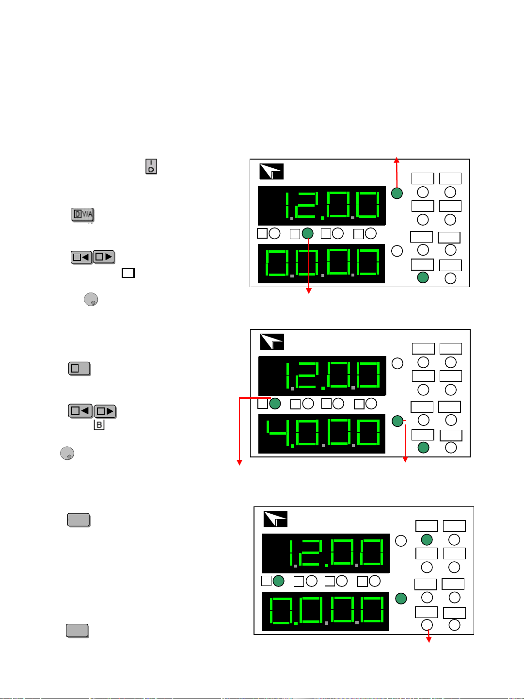
Setting the current
Check out
Press to light up the voltage setup
indicator B. It means IT6700 is in
voltage set mode, shown as fig 1.
Preset voltage
Press light up the voltage
setup indicator . Now the voltage
will rise/decline 1V once you rotary
the knob . Set the voltage to 12V.
AA
BB
Step indicator B
Press to light up the current setup
indicator A. IT6700 is in current set
mode, shown as fig 1.
D
V/A
D
V/A
Press to adjust the setup
indicator to . Now the current will
rise/decline 1V once you rotary the
knob . Set the current to 4A.
B
AA
BB
V
A
IT6720 60V/5A/100W
Auto Range DC Power Supply
CV CC
OVP OCP
OFF
Shift
Lock
Prog
ITECH
A
B
C
D
Preset current indicator
Step indicator A
Enable output
V
A
IT6720 60V/5A/100W
Auto Range DC Power Supply
CV CC
OVP OCP
OFF
Shift
Lock
Prog
ITECH
A
B
C
D
Output off indicator
Press to enable the IT6700 output.
Voltage and current settings will be wink
for three seconds,and after that , the
display value of numerical display will
change from the set value to actual
measured voltage and current value.
On/OffOn/Off
On/OffOn/Off
Power off lights will be turned off which
means the power is in output state.
Press again, you will shut power
supply’s output.
After the check of the above matters,
power on by press
Setting the voltage
The power supply usually displays the actual voltage and current values.
When you want to check the preset voltage and current values, the unit will
display automatically settings, press twice, the settings will be
displayed for three seconds.
Check the set voltage and current value
Step value for Cursor Position
A
B
C
D
Cursor position
Step voltage
Step current
------
1V
0.1V
0.01V
1A
0.1A
0.01A
0.001A
Key lock function
OVP function
OCP function
This function can prevent error operation by unauthorized person.
Press , after the was lit on, press ,
will be lit on, which means all keys on the panel except
and . Repeat above operation, key lock function will be
disabled.
V
A
IT6720 60V/5A/100W
Auto Range DC Power Supply
CV CC
OVP OCP
OFF
Shift
Lock
Prog
ITECH
A
B
C
D
Press , and press for
three seconds, now the panel
displays OVP, shown as fig 4.
ShiftShift
D
V/A
D
V/A
Use and to set OVP
value.
AA
BB
OVP voltage value
V
A
IT6720 60V/5A/100W
Auto Range DC Power Supply
CV CC
OVP OCP
OFF
Shift
Lock
Prog
ITECH
A
B
C
D
OCP current value
Press to enter into OCP
setting interface after setting OVP
value, use and to
set the OCP value.
CC
AA
BB
If the OVP and OCP settings are lower
than the actual voltage/current value, the
output of power supply will be turned off.
The default settings of IT6720 are
OVP=61V, OCP=5.1A;IT6721 OVP=61V,
OCP=8.1A.
NOTE
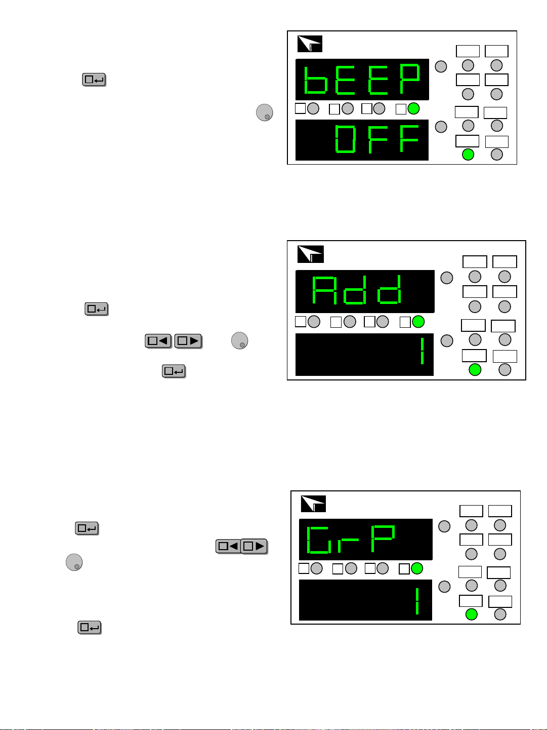
Store group setting (GRP)
V
A
IT6720 60V/5A/100W
Auto Range DC Power Supply
CV CC
OVP OCP
OFF
Shift
Lock
Prog
ITECH
A
B
C
D
Press to enter into GRP interface
after setting the OCP value, use
and to select store group.
CC
AA
BB
IT6700 allows customers to store 100
groups with A/B/C/D four set value for every
group.
Press to confirm the chosen
group and end the setup mode.
CC
Key sound (BEEP)
Press to enter the BEEP setting
Interface after finished the OCP setting,
select the ON/OFF state with the knob .
ON indicates there is key sound,
OFF means no.
CC
V
A
IT6720 60V/5A/100W
Auto Range DC Power Supply
CV CC
OVP OCP
OFF
Shift
Lock
Prog
ITECH
A
B
C
D
Power address (ADD)
Press to enter the ADD setting
interface after finishing the BEEP
setting, select the and
to enter store address setting. ADD
range: 0~30,press to confirm。
V
A
IT6720 60V/5A/100W
Auto Range DC Power Supply
CV CC
OVP OCP
OFF
Shift
Lock
Prog
ITECH
A
B
C
D
CC
AA
BB
CC
3: Check whether the indicators are lit on, if so, please reset
according to the mentioned OVP/OCP/OCP means.
If the outputs is disabled:
1: Check whether voltage and current settings are zero, if so, reset voltage
and current value.
2: Check whether the indicator is lit on, if so, press to enable the
outputs.
OFF
OVP
OCP
If the keypad is disabled, check whether the indicator is lit on, if
so, unlock the keypads as the above means.
Lock
On/OffOn/Off
Faulty disposal
When the power supply is on recall operation, that means all you can recall the
parameters from the store group. Press any key of to
recall the stored parameter.
When the power supply is on recall operation are disabled,
they only can be used with key. Press , and press to exit recall
function.CC
Press and , the indicator will be lit on, which means that
IT6720working in the shortcuts mode. Press any key in ,
recall the preset voltage/current value which has been stored.
Recall operation
In the normal working mode, set the voltage/current value to be stored.
Press and , now the Cursor will wink together. Press
any key in to save it.
Store operation
ShiftShift
A
B
C
D
AA
CC
BB
D
V/A
D
V/A
AA
ShiftShift
BB
Prog
AA
CC
BB
D
V/A
D
V/A
AA
CC
BB
D
V/A
D
V/A
AA
CC
BB
D
V/A
D
V/A
ShiftShift
ShiftShift
BB
Battery charging protection
Pay attention to the positive and negative terminals when connecting the
battery. If the battery is connected reversely to the power supply, it will
result in damage to the power supply.
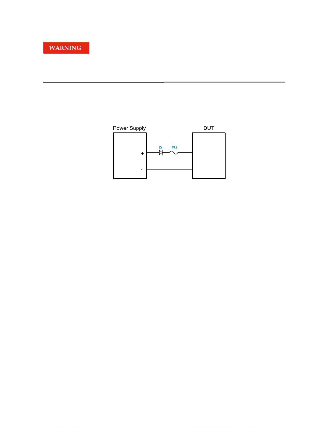
When using the power supply to charge the battery, a diode and a fuse must be
connected in series with the output as shown in the following figure to protect the
circuit . The detailed methodology is shown as follows.
The role of the diode and the fuse in the above figure is described as below.
The role of the diode is to block any reverse voltage and current flow to the
battery to protect the power supply and prevent the internal parts from damage.
The series diode can also avoid the condition that the battery discharges due
to the internal resistive load of the power supply in the power-off or output-off
state.
When selecting the diode, the user should consider the following notes.
The current capacity of the diode should be 110% of the rating current of the
battery at least. When setting the input voltage of the battery, the user need to
consider the threshold voltage of the diode. The typical threshold voltage of a
silicon diode is 0.6 V to 0.7 V. The reverse breakdown voltage of the diode
should be more than twice the rating voltage of the battery. The user also need
to consider the power of the diode and add a heat sink when necessary
The role of the fuse is to interrupt the current by melting the metal wire in it
when the current rises to a certain value, thereby protecting the circuit.
When selecting the fuse, the user should consider the following notes. The
rating current of the fuse should be 150% to 200% of the maximum current of
the battery and be less than 150% of the maximum output current of the power
supply.
Specifications
Output Rating Voltage
Current
Specifications IT6720
Load Regulation
Voltage
Current
Line Regulation
Voltage
Current
0~60V
<0.01%+3mV
<0.01%+3mA
<0.01%+3mV
<0.1%+3mA
0~5A
Specs
Power 100W
Programming Accuracy Voltage
Current
<0.05%+10mV
<0.2%+2mA
Read back Accuracy
Voltage
Current
Ripple
Current
Voltage
<0.05%+10mV
<0.1%+2mA
<2.0mV rms
<5mA rms
Dimension
88*175*282(mm)
W*H*D
Weight
Net
<2.5Kg
0~60V
0~8A
180W
<0.01%+5mV
<0.01%+5mA
<0.01%+5mV
<0.1%+5mA
<0.05%+10mV
<0.3%+5mA
<0.05%+10mV
<0.3%+5mA
<5.0mV rms
<8mA rms
88*175*282(mm)
<3.5Kg
IT6721
Maximum input
apparent power
300VA 700VA
Contact US
Thank you for purchasing ITECH products. If you have any doubt about this product, please
contact us as follow.
1. Please refer to the CD-ROM of related user’s manual in package.
2. Click www.itechate.com
or scan the right two-dimension code
to visit the ITECH website.
3. Send E-mail to fae@itech.sh or dial the service hot-line in China: 4006025000
4. Select the most convenient contact method for further consultancy.