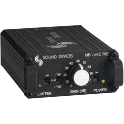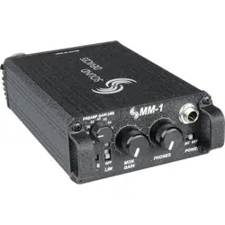
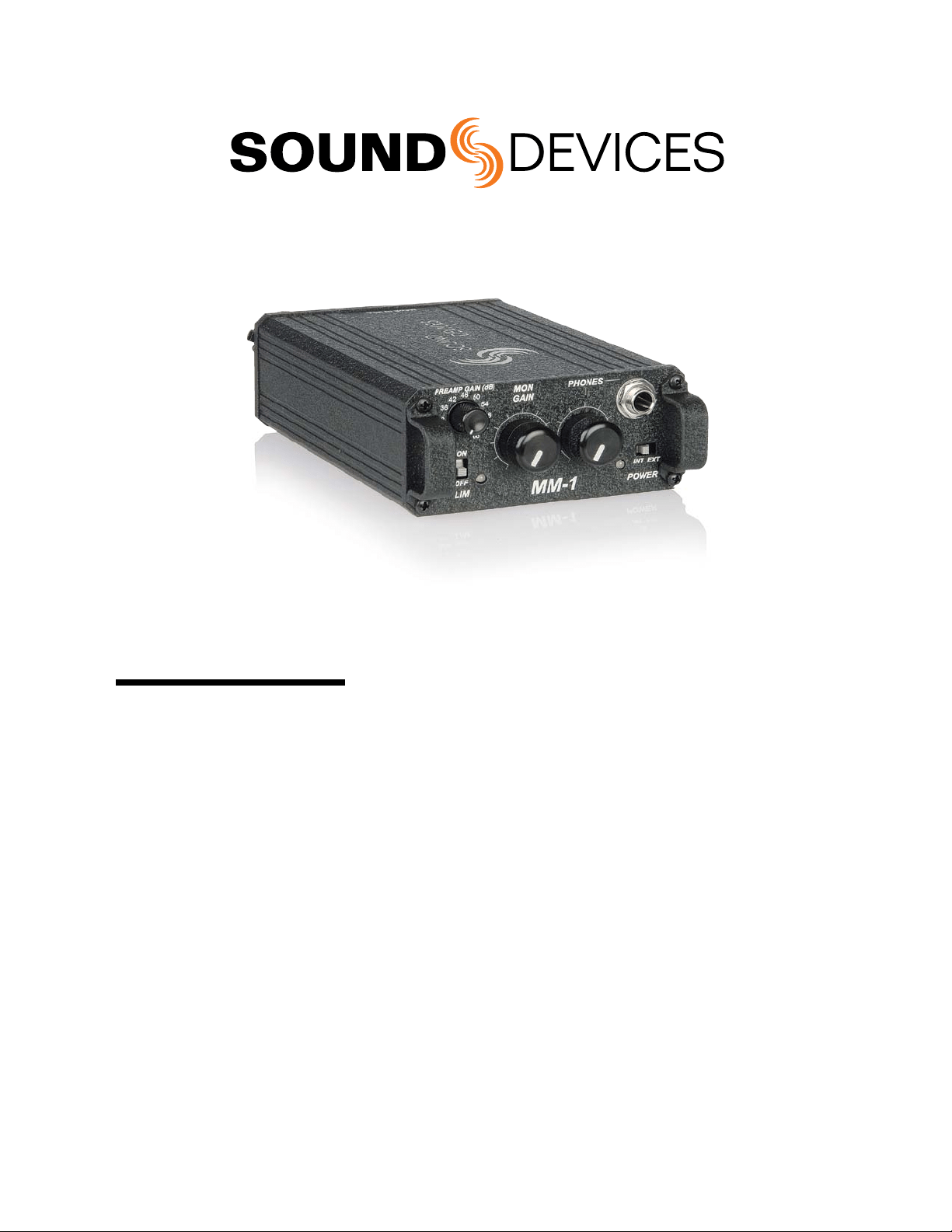
MM-1
Microphone Preamplifier
with Headphone Monitor
User Guide and Technical Information
Sound Devices, LLC
E7556 State Rd. 23/33 • Reedsburg, WI • USA
+1 (608) 524-0625 • fax: +1 (608) 524-0655
Toll-Free: (800) 505-0625
www.sounddevices.com
suppor[email protected]

MM-1 User Guide and Technical Information
2
Features and specifications are subject to change. Visit www.sounddevices.com for the latest documentation.
General Description
Sound Devices MM-1 combines a high-performance microphone preamplifier with a flexible
headphone monitor.
The full-featured, transformer-balanced microphone preamp produces low-noise, low-distortion
gain at all switch positions. Its dual-stage limiter and high-pass filter prevent occasional signal
extremes from overloading down-stream equipment.
The MM-1 is at home in a range of applications—film sound (boom operators), high-definition
television production, corporate/industrial environments, radio/television announce booths, and
music production. With its headphone monitoring function the MM-1 is a benefit in applications
where communications channels and mix-minus feeds need to be monitored in headphones. The
user can monitor both microphone audio and external audio sources in headphones with level
control.
The MM-1 is designed for durability. Its extruded aluminum chassis, rugged end panels, machined
knobs, and panel mounted connectors assure reliable mechanical operation.
Features
High Performance Microphone Preamplifier
• Maximumof66dBofgain,inelevendiscretestepsforaccurate,repeatablegainsettings.
• Dynamicrangeexceeding120dB
• 10Hzto50kHzaudiobandwidth.
• HighimmunitytoRFinterferenceduetotransformers,RFltering,andall-metalconstruction
• Highcurrentlineoutputdrivercapableofdrivingverylongcableruns.
• PremiumLundahlinputtransformerwithsuperiorsonicqualityandfreedomfrominterferenceprob-
lems.
• Extendedrangepeaklimiterviadualopto-isolatorsmakespreampliervirtually“unclippable”.
• Selectable48-volt/12-voltphantompoweror12-voltT-powerforcondensermicrophones.
• High-passlterwithtwoselectablecornerfrequencies,80and160Hz,6dBperoctave.
Headphone Monitoring
• Headphonemonitoringofmicrophoneaudio,externalmonitoraudio,oramixofboth.
• Monitorinputacceptsbalancedorunbalancedmonoline-levelinputson1/4-inchtip-ring-sleeveconnec-
tor.
• SeparatelevelcontrolofMonitorgainandoverallheadphonegain.
• SplitearfunctionviaDIPswitches.
Portable
• Internalbatterypower(two-AA)forconvenient,lowcostpower.
• Excellentbatterylifewithalkalineorlithiumprimarycells.
• External5–17VDCpowering(plugincluded).
Durable Mechanical Construction
• Highstrengthaluminumchassiswithstandspunishingeldconditions.
• Panel-mountedconnectorsforstrengthandreliability.
• Easyaccessbatterycompartmentforquickbatterychanges.
• Durablebeltclipandendpanels.
MM-1 User Guide and Technical Information
3
Specications
Gain: (Mic to Line)
0 dB to 66 dB input to output, switch selectable
Gain Accuracy (Mic - Line)
+0.6, –0.1 dB with reference to front panel gain markings
(150 ohm source, 100k ohm load impedances)
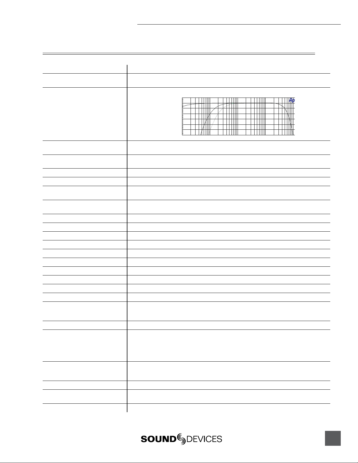
Frequency Response
(Mic - Line)
20 Hz –20 kHz, +0.1, -0.5 dB, –1 dB at 50 kHz (relative to 1 kHz level with 150 ohm source)
MM-1 Frequency
Response
-- w/80 Hz HP
·· w/160 Hz HP
-6
+1
-5
-4
-3
-2
-1
+0
d
B
u
10 100k20 50 100 200 500 1k 2k 5k 10k 20k 50k
Hz
Equivalent Input Noise: (Mic)
–126 dBu (–128 dBV) maximum
(150 ohm source, flat weighting, 22 Hz – 22 kHz bandwidth gain setting 36 dB or greater)
Output Clipping Level: (Line)
+22 dBu minimum with 100k ohm load
+20 dBu minimum with 600 ohm load
Input Clipping Level: (Mic)
+4 dBu minimum at the 0 or +18 dB gain setting
Dynamic Range: (Mic to Line)
122 dB minimum at the +18 dB gain setting
THD + Noise:
.05% maximum (from 50 Hz – 22 kHz @ +4 dBu output level, 22 Hz – 22 kHz filter bandwidth,
+46 dB gain setting
Common Mode Rejection Ratio:
100 dB minimum at 80 Hz
60 dB minimum at 10 kHz
Input (Mic):
Transformer-balanced, 2k ohm input impedance
Input: (Monitor)
Electronically-balanced, 22k ohm input impedance
Output: (Line)
Transformer-balanced, 130 ohm output impedance
Headphone Output Impedance:
Unbalanced, 200 ohms
Frequency Response: (Monitor In)
10 Hz – 50 kHz, ±0.5 dB, gain at 50 %
Frequency Response (headphones):
10 Hz – 50 kHz, ±0.5 dB, gain at 50%
Input Clipping Level: (Monitor In)
Greater than +30 dBu
High-Pass Filter:
80 Hz or 160 Hz (switch selectable), 6 dB per octave
Phantom Power:
12 V or 48 V (switch selectable), will supply 10 mA per DIN 45 596 specification
T-Power:
12 V via 180 ohm resistors, will supply 10 mA
Limiter:
Limits to +17 dBu output level, 10:1 limiting ratio
5 ms attack time, 100 ms release time
Amber/Red LED indicates limiting/clipping
Internal Voltage Rails:
±15 V, regulated
Power:
Internal: 2 x AA batteries
External: 5–17 VDC via threaded coaxial jack, (5.5 mm outer diameter, 2.1 mm inner diameter),
pin positive, sleeve negative.
Voltages above 17 VDC cause no damage to unit but will open an internal poly fuse. Poly fuse will
reset when voltage is removed.
Polarity:
All inputs to all outputs are non-inverting
XLR – pin-2 = hot, pin-3 = cold, pin-1 is ground
TRS – Tip = hot, ring = cold, sleeve = ground
Weight: (unit only)
0.64 kg, 1.42 lbs.
Dimensions: (unit only)
49 mm x 95 mm x 166 mm (h x w x d)
(1.95” x 3.75” x 6.55”)
Included Accessories:
Mating DC coaxial power connector, 4 rubber feet
MM-1 User Guide and Technical Information
4
Features and specifications are subject to change. Visit www.sounddevices.com for the latest documentation.
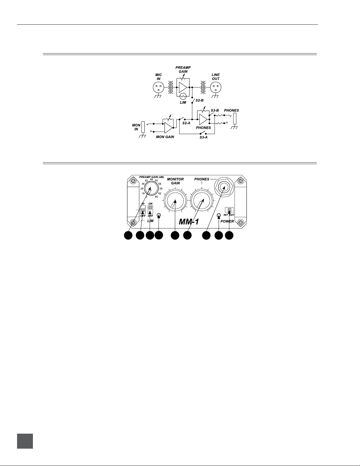
Block Diagram
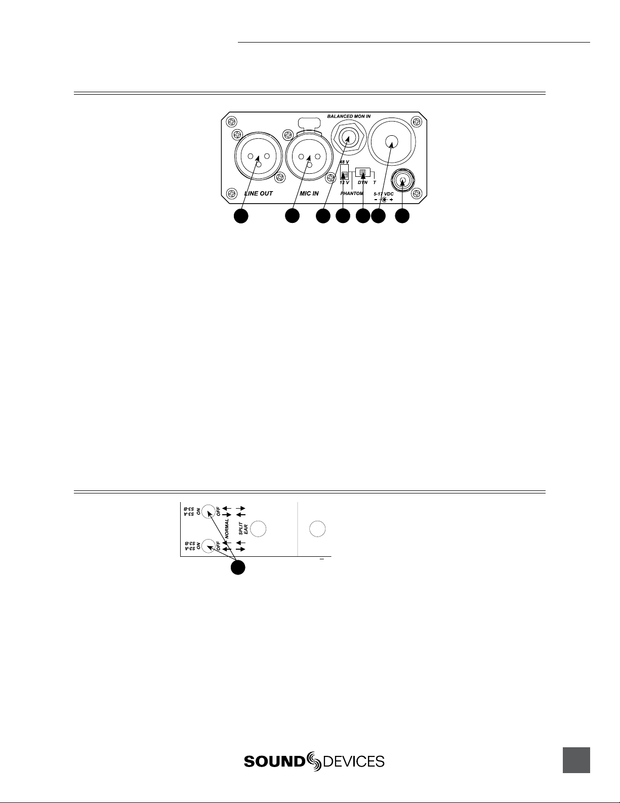
Front Panel Controls and Connectors
1
6
7
2
3
4
5
8
9
1) Preamp Gain Switch (Rotary)
Selects the amount of gain from input to
output, adjustable in 11 increments.
2) High-Pass Filter Switch
Three-positionswitchinsertsan80Hz
or160Hzcornerfrequencylter,6dB
per octave. Off position removes the
filter from the signal path.
3) Limiter Switch
Activatesthepeaklimiter.Limitsto+17
dBuoutput.
4) Limiter/Peak LED
Bi-colorLEDilluminatesredat3dB
below clipping; illuminates amber to
indicate limiter activity.
5) Monitor In Gain
ControlsthelevelofMonitorInput
signal.
6) Phones Gain
Controlstheoverallheadphonemonitor
level of both preamp audio and monitor
audio.
7) Headphone Connector
1/4-inchTRSmonoheadphoneoutput;
microphone audio and/or monitor
audio in headphones.
8) Power LED
Bi-colorLEDilluminatesgreenwhen
the unit is powered and changes to
red when approximately four hours of
battery life remain.
9) Power Switch
Selects the power source for the unit,
eitherInternal(battery)orExternal
power.
MM-1 User Guide and Technical Information
5
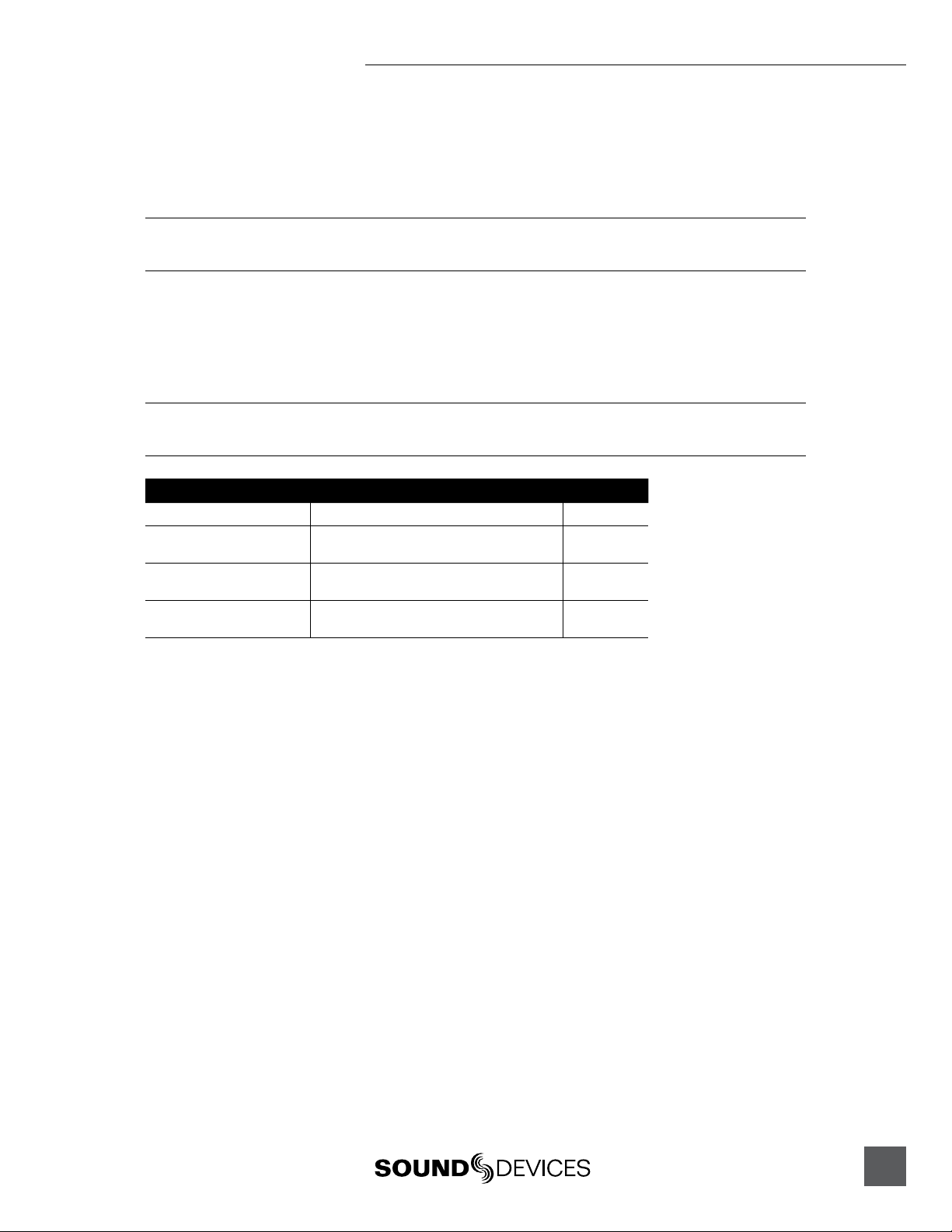
Back Panel Controls and Connectors
1
2
6
3
4
75
1) Line Out
Transformer-balanced line-level output.
+22dBupeakoutputlevel.
2) Mic In
Transformer-balancedXLRinputaccepts
microphone level signals.
3) Balanced Monitor Input
Active-balanced¼-inchconnector
accepts balanced or unbalanced line
levelsignalsfrom-10dButo+24dBu.
4) Phantom Voltage Switch
Selectsphantomvoltagesbetween48V
or12Vformicpowering.
5) Microphone Power Switch
Three-position switch selects Phantom
power,T-power(12Volts),ornopower
(DYN position).
WARNING:DonotuseT-powering
with phantom powered or dynamic
microphones(see“Microphone
Powering”).
6) Battery Compartment
RequirestwoAAbatteriesforoperation.
Insertpositive(+)endofbatteryrst
7) External DC Input Connector
Accepts5–17VDC,
pin(+),sleeve(–)..
Bottom Panel Switches
1
The bottom panel switches are
accessible when the belt clip is
removed. Use a 1/16-inch allen-
head wrench.
1) DIP Switches
The“SplitEar”settingallowsthea
signal to be sent to the left headphone
earpiece and a monitor signal to be sent
totherightearpiece.Also,S2-Bcan
mute the mic audio to the headphones.

MM-1 User Guide and Technical Information
6
Features and specifications are subject to change. Visit www.sounddevices.com for the latest documentation.
Operational Notes
Transformers
The isolation characteristics of transformers are superior to any other balancing technique,
particularly for the adverse and uncontrolled environments of field production. Transformers
provide galvanic isolation from the driving source, meaning there is no direct electrical connection.
Signalsare“transformed”magnetically.BothtransformersintheMM-1usepremiummagneticcore
material to achieve high signal handling capability (especially at low frequencies) while keeping
distortiontoaminimum.Becauseoftheirinherentlyhighcommonmodeimpedance,transformers
are unrivaled by any other type of input for common-mode noise rejection.
BoththemicrophoneinputandlineoutputoftheMM-1canbebalancedorunbalancedwithout
problems. When unbalancing (either input or output) ground pin 3 to pin 1. There is no change in
gain with an unbalanced connection into or out of the MM-1.
Microphone Powering
Microphonesrequiringphantompowershouldusethelowestvoltageacceptabletomaximize
batterylife.Mostelectret-condensermicrophonescanoperateonphantomvoltagesfrom11-52volts.
Thereistypicallynoperformancebenettousing48-volt;therefore12-voltphantomisappropriate.
Somemicrophoneswhichrequire48-voltphantomwillnotoperate,ormayoperatewithlower
headroomandincreaseddistortionat12volts;thereforeuse48-voltphantom.Consultyour
microphone documentation for the appropriate voltage.
Dynamicmicrophonesdonotrequirephantompower.Aproperlyconnectedbalanced,dynamic
microphone will not be affected by the presence of phantom power nor will it draw any current.
However, it is good practice to turn phantom power off if the microphone cable is suspect. Poor or
incorrectly wired microphone cable can cause audible artifacts in the microphone signal. (Phantom is
an excellent cable tester.)
T-powering is a specific powering topology needed only for T-powered microphones. T-power
electricallyis12voltsappliedtopin2withrespecttopin3oftheXLRconnector.Becauseofthe
voltage differential of T-power, it is incompatible with dynamic or phantom powered microphones
and can permanently damage dynamic and phantom powered mics.
High-Pass Filter
The two positions of the high-pass filter (low-cut) in the MM-1 are useful for removing excess low
frequencyenergyintheaudiosignals.The80Hzpositionisappropriatewhenrecordinggeneral
speech,music,andambientsound.The160Hzpositionisusefultoenhancespeechclarity.Thehigh
passlterisasinglepoledesign,6dBperoctave.
Whenpossible,attempttoequalizeatthesoundsourcewithmicrophoneselection,useofa
windscreen,microphoneplacement,andonboardmicrophoneltering.Ahigh-passlteronthe
microphone and a high-pass filter on the MM-1 will give an additive effect, increasing the slope of
the filter.
Limiter
The MM-1 has a built-in peak responding limiter which can be turned on or off by the front panel
switch. The MM-1 limiter is two separate limiters circuits activated by the one switch; the first limiter
keepstheinputgainstagefromclipping,andthesecondlimiterlimitstheoutputto+17dBu.The
twolimitersenabletheMM-1tolimitinexcessof50dB,meaningthatitisverydifculttoclipthe
unit,nomatterthegainsetting.TheLimiterLEDonthefrontpanelilluminatesamberinproportion
to the amount of limiting.
MM-1 User Guide and Technical Information
7
Headphone Monitoring
With headphones connected to the front panel headphone jack the MM-1 can be used to monitor
either microphone audio, monitor audio, or a mix of both signals. The Phones level controls the
overallheadphonevolume.TheMonitorGainadjuststhelevelofthemonitorinputsignal.
The MM-1 is capable of driving headphones to dangerously high levels. Take precautions to prevent
hearing damage.
Battery Life
Several factors affect battery life, including battery chemistry, ambient temperature of operation,
microphonepowering,andheadphonedrivelevels.Experimentationisrecommendedtodetermine
battery life for each individual setup.
Nickel-cadmium batteries are not recommended in the MM-1. These batteries have low energy per cell
versus other types and provide very short operation.
Battery Type Operational Characteristics Battery Life
Duracell AA MN 1500 powered, idle 20 hrs.
Duracell AA MN 1500 dynamic microphone, +4 dBu output, 75
ohm headphones at moderate level
14 hrs.
Duracell AA MN 1500 condenser microphone (48V), 75 ohm head-
phones at high levels
8 hrs.
2000 mAh NiMH AA dynamic microphone, +4 dBu output, 75
ohm headphones at moderate level
17 hrs.
(Test conditions: 70º F)
MM-1 User Guide and Technical Information
8
Features and specifications are subject to change. Visit www.sounddevices.com for the latest documentation.
Application Notes
Line Driving/Mic Checking
Audiofromremotemicrophoneslocatedmorethan100metersfromamixingconsoleimprovewhen
sendinglinelevelsignalstothemixposition.Longcablerunsatmicrophonelevelaremoreprone
to noise and interference than line level signals. Phantom voltages can also drop over long cable
runs—resulting in problems at the microphone. The MM-1 can be used to step microphone signals
to line level, provide power to microphones, transformer-isolate grounds, and to verify microphone
audio in headphones.
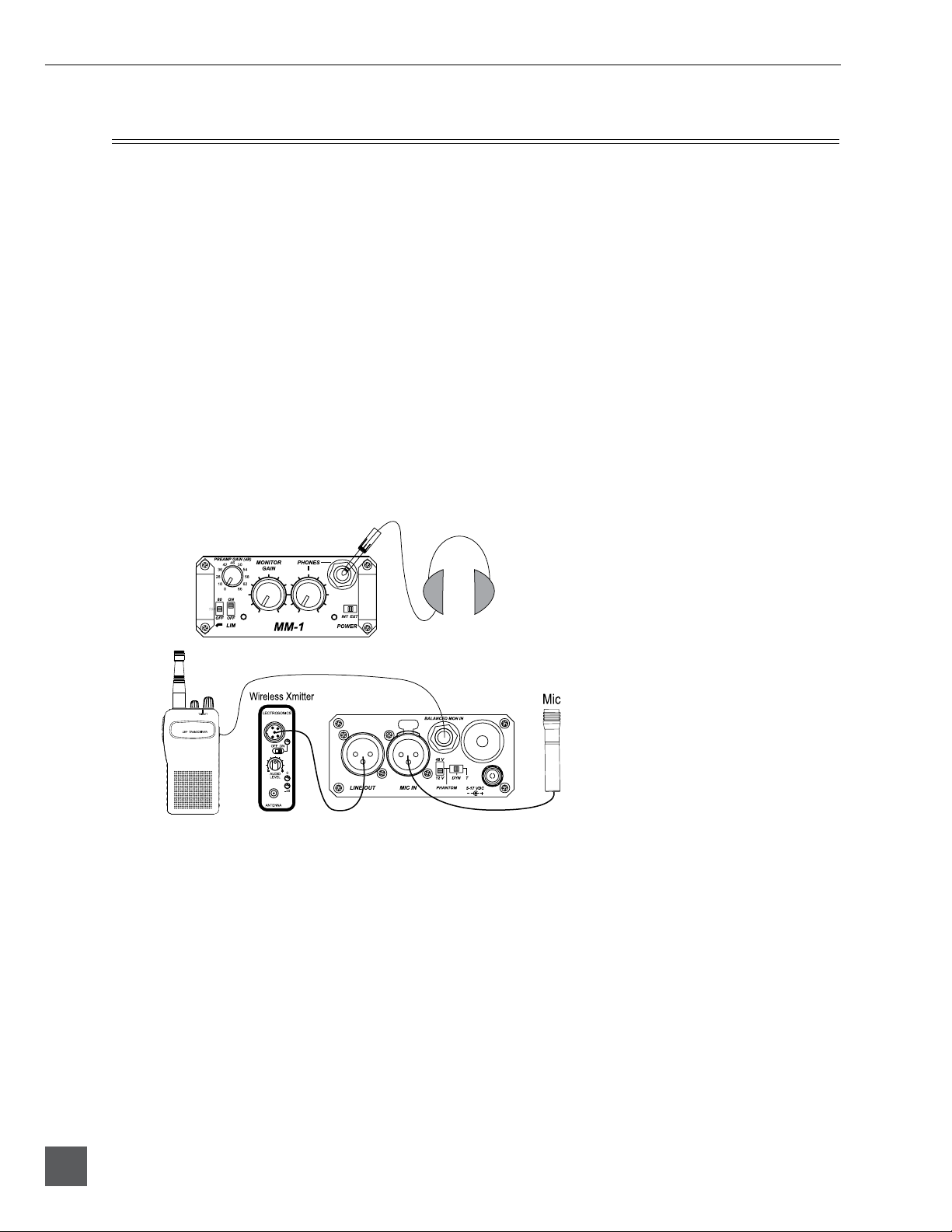
Wireless Boom Operator
The MM-1 can be used to allow a boom operator to have an un-tethered connection to a production
vanormixposition.ThemicrophoneisconnecteddirectlytotheMM-1,andthe“boomop”can
hear microphone audio directly in headphones. The MM-1 is used to power the microphone and
providegain.TheoutputoftheMM-1isconnectedtoabody-packwirelesstransmitter.Atwo-way
radio’searpieceoutputisconnectedtothemonitorinputoftheMM-1.Viathetwo-waytheboom
operator receives director’s cues. The MM-1 allows the user to control monitoring levels of the comm
feed and the microphone signal in headphones without affecting the microphone signal sent to the
wireless transmitter.
Boom Operator
MM-1 User Guide and Technical Information
9
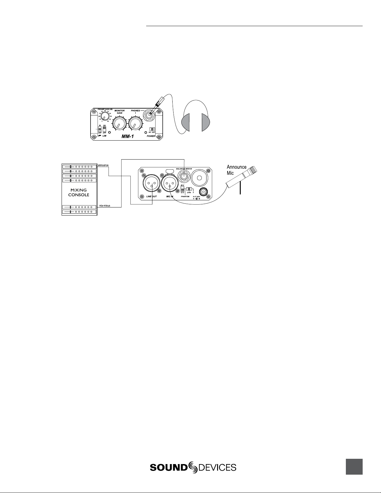
Radio/Television Announcer Position
The MM-1 is used as a microphone preamplifier for an announcer’s microphone and can pass a mix-
minus headphone feed to the announcer. Sending a line level signal from the announcer position
to the main mixing console is preferred over sending a mic level signal. When engaged, the limiter
prevents distortion during shouting and high microphone signal levels.
Announcer
In the set-up above the announcer has level control in the headphones of their overall audio level
and the level of the mix-minus feed.
Podium Microphones
Oftenpodiummicrophoneshavelongcablerunsand“see”multipleaudioconsoles.UsinganMM-1
between podium microphones and mixing consoles provides needed isolation for the microphone.
BecausetheMM-1hastransformercouplingforbothinputsandoutputsthepotentialforground
loops is substantially reduced. Driving line level signals to mixing consoles and powering
microphones locally greatly improves the reliability and audio quality of a podium mic feeds. The
microphone is connected directly to the MM-1, which provides gain, microphone power, filtering,
and limiting. In addition, the microphone signal can be verified using the headphone output of the
MM-1.
MM-1 User Guide and Technical Information
10
Features and specifications are subject to change. Visit www.sounddevices.com for the latest documentation.
CE Declaration of Conformity
AccordingtoISO/IECGuide22
SoundDevices,LLC
E7556StateRd.23/33
Reedsburg,WI53959USA
declaresthattheproduct,MM-1isinconformitywithandpasses:
EN55103-1, 1997 EMC-product family standard for audio, video, audio-visual and enter-
tainment lighting control apparatus for professional use. Part 1: Emissions
EN55103-2, 1997 EMC-product family standard for audio, video, audio-visual and enter-
tainment lighting control apparatus for professional use. Part 2: Immunity
EN55103-1 Phenomena 2, 3, 1997 Magnetic emissions at 1 meter 50 Hz – 50 kHz
EN55103-2 Phenomena 3, 1997 Magnetic immunity 50 Hz to 10 kHz
CISPR 22 (EN55022) 2003 Radiated and conducted emissions, Class B
EN61000-4-2 (2001)/
IEC61000-4-2 (2001)
ESD, ±4 kV contact, ±8 kV air discharge
EN61000-4-3 (2001)/
IEC1000-4-3 (2001)
Radiated RF immunity, 10 V/m, 80% 1 kHz amplitude modulation
EN61000-4-4 (2001)/
IEC61000-4-4 (2001)
AC power ports: EFT Burst, I/O lines, ±0.25 kV to ±1.0 kV, power line
±0.5 kB – ±1 kV
EN61000-4-4 (2001)/
IEC61000-4-4 (2001)
EFT Burst, I/O lines, ±0.25 kV to ±1.0 kV, power line ±0.5 kB – ±1 kV
EN61000-4-5 (2001)/
IEC61000-4-5 (2001)
Surge ±1 kV differential mode (line-to-line), ±2 kV common mode (line-
to-ground)
EN61000-4-6 (2001)/
IEC61000-4-6 (2001)
Conducted RF immunity, 3 V, 80% @1 kHz amplitude modulation
EN61000-4-11 (2002)/
IEC61000-4-11(2001)
Voltage dips and short interruptions at test voltage level: 0% V unominal
@ 70% V unominal @ 25 period
TestedbyL.S.Compliance,Inc.Cedarburg,Wisconsin
February15,2003
MatthewAnderson
DirectorofEngineering
SoundDevices,LLC

MM-1 User Guide and Technical Information
11
FCC Statement
This device has been tested and found to comply with the limits for a class B digital device, pursuant to part 15 of the FCC rules. These
limits are designed to provide reasonable protection against harmful interference in a residential installation. This equipment generates,
uses, and can radiate radio frequency energy and, if not installed and used in accordance with the instructions, may cause harmful
interference to radio communications. However, there is no guarantee that interference will not occur in a particular installation.
Warranty
SoundDevices,LLCwarrantstheMM-1MicrophonePreampwithHeadphoneMonitoringagainst
defectsinmaterialsandworkmanshipforaperiodofONE(1)yearfromdateoforiginalretail
purchase. This is a non-transferable warranty that extends only to the original purchaser. Sound
Devices,LLCwillrepairorreplacetheproductatitsdiscretionatnocharge.Warrantyclaims
duetosevereserviceconditionswillbeaddressedonanindividualbasis.THEWARRANTY
ANDREMEDIESSETFORTHABOVEAREEXCLUSIVE.SOUNDDEVICES,LLCDISCLAIMS
ALLOTHERWARRANTIES,EXPRESSORIMPLIED,INCLUDINGWARRANTIESOF
MERCHANTABILITYANDFITNESSFORAPARTICULARPURPOSE.SOUNDDEVICES,LLCIS
NOTRESPONSIBLEFORSPECIAL,INCIDENTAL,ORCONSEQUENTIALDAMAGESARISING
FROMANYBREACHOFWARRANTYORUNDERANYOTHERLEGALTHEORY.Becausesome
jurisdictions do not permit the exclusion or limitations set forth above, they may not apply in all
cases.
Forallservice,includingwarrantyrepair,pleasecontactSoundDevicesforareturnauthorization
number(RMA)beforesendingtheunitforservice.Servicereturnsshouldbesentto:
SoundDevices,LLC
ServiceRepair(RMA#XXXX)
E7556StateRd.23/33
Reedsburg,WI53959USA
telephone:(608)524-0625

MM-1 User Guide - Printed in U.S.A.