Loading ...
Loading ...
Loading ...

7
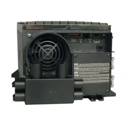
Set Battery Charge Conserver (Load Sense) Dial—OPTIONAL
In order to save battery power, the unit’s inverter automatically shuts off in the absence of any power demand from
connected equipment or appliances (the electrical load). When the unit detects a load, it automatically turns its inverter
function on. Users may choose the minimum load the Inverter/Charger will detect by adjusting the Battery Charge Conserver
Dial (see diagram). Using a small tool, turn the dial clockwise to lower the minimum load that will be detected, causing the
inverter to turn on for smaller loads. When the dial is turned fully clockwise, the inverter will operate even when there is no
load. Turn the dial counterclockwise to increase the minimum load that will be detected, causing the inverter to stay off until the new
minimum load is reached.
Note: the factory setting for the dial is fully clockwise. However, based on the threshold load to which you’d like the inverter to respond, you should adjust the dial counterclockwise to reduce its
sensitivity until the inverter is active only when connected equipment or appliances are actually in use.
Connect Remote Control—OPTIONAL
Model features a 8-conductor telephone style receptacle on the front panel for use with an optional remote control module (Tripp Lite model
APSRM4, sold separately). The remote module allows the Inverter/Charger to be mounted in a compartment or cabinet out of sight, while
operated conveniently from within the living area or control panel of your RV. See instructions packed with the remote control module.
Connect Battery Temperature Sensing Cable—OPTIONAL
The battery temperature sensing function prolongs battery life by adjusting the charge float voltage level based on battery temperature.
Connect the sensor cable (the cable, included with select models, has an RJ style connector on one end and a black sensor on the other) to
the RJ style jack located on the side of the Inverter/Charger labeled “Remote Temp. Sense.” With user-supplied electrical or duct tape, affix
the sensor to the side of the battery below the electrolyte level. Make sure that nothing, not even tape, comes between the sensor and the
side of the battery. To guard against false readings due to ambient temperature, place the sensor between batteries, if possible, or away from
sources of extreme heat or cold. If the sensor cable is not used, the Inverter/Charger will charge according to its default 25º C values.
Utilize Automatic Generator Starter Capability—OPTIONAL
Model includes a RJ type modular jack on the side panel labeled “Generator Start”. Attach to vehicle generator
ON/OFF switching mechanism with user-supplied cable (see Pin Configuration Diagram). Once attached, the
interface will allow the Inverter/Charger to automatically switch a vehicle generator on when connected battery
voltage levels are low (11.6 VDC) and switch it off when battery voltage levels are high (14.1 VDC).
Connect Ignition Switch Control Jack—OPTIONAL
This jack (located on the Inverter’s side panel) can be used to connect the Inverter to your vehicle's ignition switch in order to automatically
control the Inverter. This connection is optional; the Inverter will function without this connection.
1
2
3
4
5
6
Pin Configuration
2 - Common
3 - N.C.
(Normally Closed)
4 - N.O.
(Normally Open)
Configuration
(continued)
Loading ...
Loading ...
Loading ...