Loading ...
Loading ...
Loading ...
A
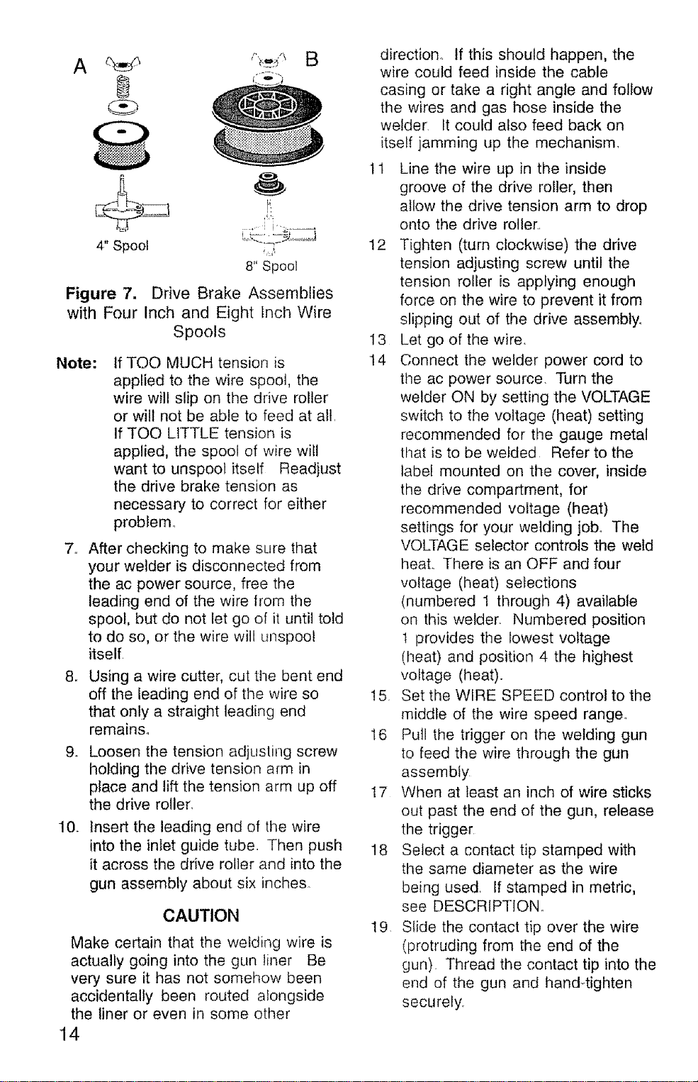
4" Spool ....:
8" Spool
Figure 7. Drive Brake Assemblies
with Four Inch and Eight Inch Wire
Spools
Note:
,,
aN
.
10.
tf TOO MUCH tension is
applied to the wire spool, the
wire will slip on the drive roller
or will not be able to feed at all.
If TOO LITTLE tension is
applied, the spool of wire will
want to unspool itself Readjust
the drive brake tension as
necessary to correct for either
problem,
After checking to make sure that
your welder is disconnected from
the ac power source, free the
leading end of the wire from the
spool, but do not let go of it until told
to do so, or the wire will unspool
itself.
Using a wire cutter, cut the bent end
off the leading end of the wire so
that only a straight leading end
remains.
Loosen the tension adjusting screw
holding the drive tension arm in
place and lift the tension arm up off
the drive roller.
Insert the leading end of the wire
into the inlet guide tube Then push
it across the drive roller and into the
gun assembly about six inches,
CAUTION
Make certain that the welding wire is
actually going into the gLm liner Be
very sure it has not somehow been
accidentally been routed alongside
the liner or even in some other
14
direction. If this should happen, the
wire could feed inside the cable
casing or take a right angle and follow
the wires and gas hose inside the
welder. It could also feed back on
itself jamming up the mechanism.
11 Line the wire up in the inside
groove of the drive roller, then
allow the drive tension arm to drop
onto the drive roller_.
12 Tighten (turn clockwise) the drive
tension adjusting screw until the
tension roller is applying enough
force on the wire to prevent it from
slipping out of the drive assembly,
13 Let go of the wire.
t4 Connect the welder power cord to
the ac power source. Turn the
welder ON by setting the VOLTAGE
switch to the voltage (heat) setting
recommended for the gauge metal
that is to be welded Refer to the
label mounted on the cover, inside
the drive compartment, for
recommended voltage (heat)
settings for your welding job. The
VOLTAGE selector controls the weld
heal There is an OFF and four
voltage (heat) selections
(numbered 1 through 4) available
on this welder. Numbered position
t provides the lowest voltage
(heat) and position 4 the highest
voltage (heat).
15 Set the WIRE SPEED control to the
rniddfe of the wire speed range,
16 Pull the trigger on the welding gun
to feed the wire through the gun
assembly
17 When at least an inch of wire sticks
out past the end of the gun, release
the trigger
18 Select a contact tip stamped with
tile same diameter as the wire
being used. If stamped in metric,
see DESCRIPTION,.
19, Slide the contact tip over the wire
(protruding from the end of the
gun) Thread the contact tip into the
end of the gun and hand-tighten
securely,
Loading ...
Loading ...
Loading ...