Loading ...
Loading ...
Loading ...
Motor
Shat{
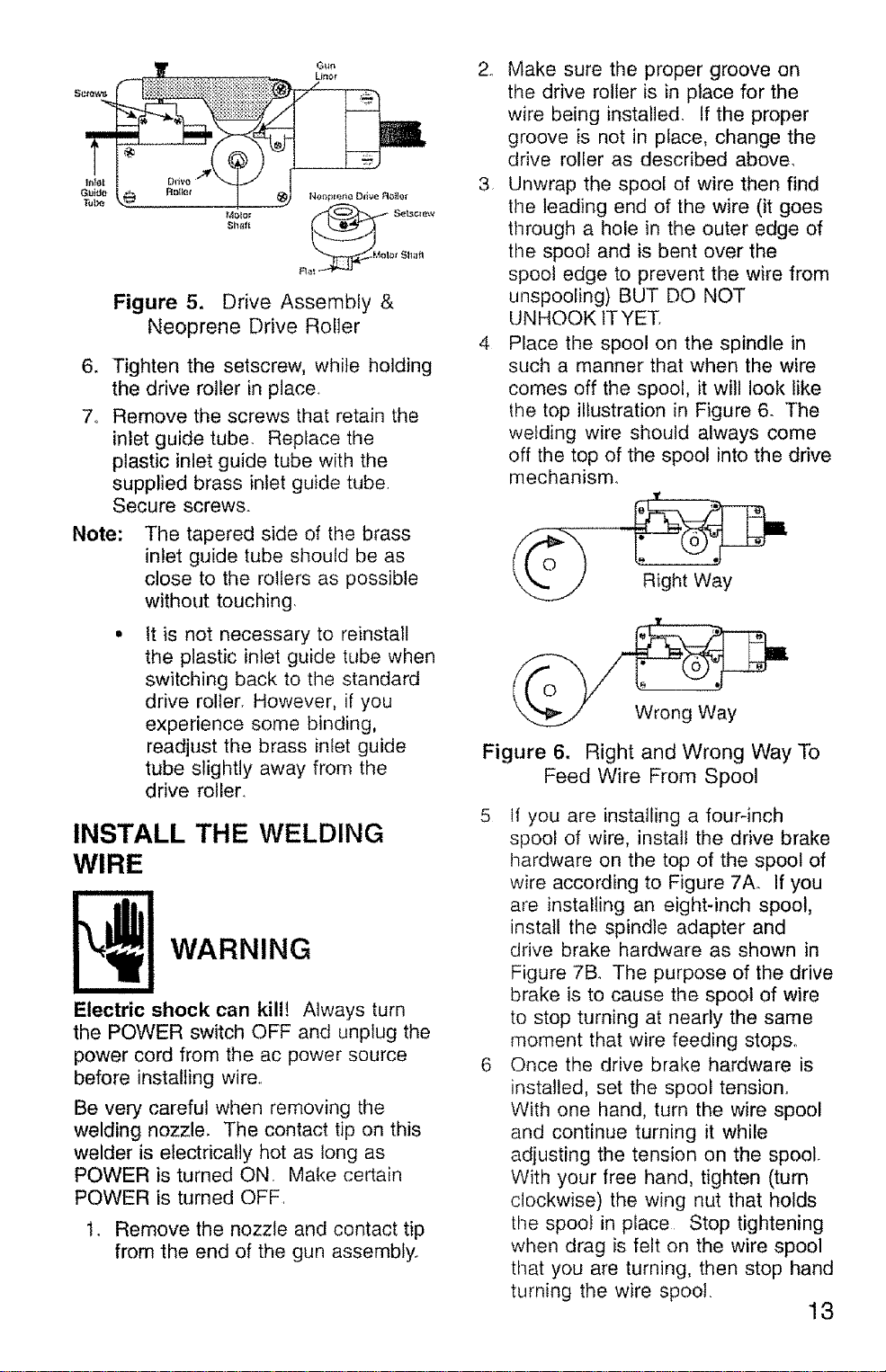
Figure 5. Drive Assembly &
Neoprene Drive Roller
6. Tighten the setscrew, while holding
the drive roller inplace
7o Remove the screws that retain the
inlet guide tube. Replace the
plastic inlet guide tube with the
supplied brass inlet guide tube
Secure screws.
Note:
The tapered side of the brass
inlet guide tube should be as
close to the rollers as possible
without touching,
It is not necessary to reinstall
the plastic inlet guide tube when
switching back to the standard
drive roller. However, if you
experience some binding,
readjust the brass inlet guide
tube slightly away from the
drive roller.
INSTALL THE WELDING
WIRE
WARNING
Electric shock can kill! Always turn
the POWER switch OFF and unplug the
power cord from the ac power source
before installing wire.,
Be very careful when removing the
welding nozzle. The contact tip on this
welder is electrically hot as long as
POWER is turned ON, Make certain
POWER is turned OFF,
t. Remove the nozzle and contact tip
from the end of the gun assembly..
2. Make sure the proper groove on
the drive roller is in place for the
wire being installed, if the proper
groove is not in place, change the
drive roller as described above,
3 Unwrap the spool of wire then find
the leading end of the wire (it goes
through a hole in the outer edge of
time spool and is bent over the
spool edge to prevent the wire from
unspooling) BUT DO NOT
UNHOOK IT YET,
4 Place the spool on the spindle in
such a manner that when the wire
comes off the spool, it will look like
the top illustration in Figure 6. The
welding wire should always come
off the top of the spool into the drive
mechanism.
Figure 6, Right and Wrong Way To
Feed Wire From Spool
5 tf you are installing a fourqnch
spool of wire, install the drive brake
hardware on the top of the spool of
wire according to Figure 7Ao If you
are installing an eight-inch spool,
install the spindle adapter and
drive brake hardware as shown in
Figure 7B. The purpose of the drive
brake is to cause the spool of wire
to stop turning at nearly the same
moment that wire feeding stops.
6 Once the drive brake hardware is
installed, set the spool tension°
With one hand, turn the wire spool
and continue turning it while
adjusting the tension on the spool.
With your free hand, tighten (turn
clockwise) the wing nut that holds
time spool in place Stop tightening
when drag is felt on the wire spool
that you are turning, then stop hand
turning the wire spool.
13
Loading ...
Loading ...
Loading ...