Loading ...
Loading ...
Loading ...
EVID
TM
Owner’s Manual
9
Product Description
Step 4: Mount the Speaker to the
Bracket
First remove the two Phillips-head screws
on the rear of the enclosure. Use the
supplied eyebolt to mount one mounting
clip to the top of the speaker as shown in
Figure 24. Check to make sure that the
wiring connections to the amplifier and the
satellite speakers are correct and secure.
For corner mounting
Attach the four rubber mounting feet to the
front side edges, and secure the safety
line to the eyebolt. Lift the enclosure up to
the ceiling and center it back it into the
corner until it touches the bracket rungs,
then carefully lower it so the top clip hooks
over the top rung of the bracket (1). Insert
one of the 3/8-16-thread Phillips-head
screws through the remaining clip and,
with the clip pointing up, thread the screw
finger-tight into the lower mtg. hole on the
enclosure (2, 3). Level the clip and tighten
securely with a #3 right-angle Phillips
screwdriver.
For midwall mounting
Attach the four rubber mounting feet inside
the corners on the side of the enclosure
that will be against the wall and attach the
safety line to the eyebolt. Insert one of the
3/8-16-thread Phillips-head screws
through the remaining clip and keep it
within arm's reach. Lift the enclosure up to
the ceiling and bring its back into contact
with the bracket rungs. Slide the enclosure
sideways to engage the clip over one
bracket rung (1) and, while holding it tight
against both rungs, insert the 3/8-16-
thread screw with its clip into the remain-
ing mounting hole so the clip engages the
remaining bracket rung (2, 3). Finger-
tighten the screw and straighten the clip.
The enclosure may now be released. It will
slide down the rungs until the four rubber
feet are snug against the wall. Using a #3
right-angle Phillips screwdriver, securely
tighten the second Phillips-head screw.
Gently rotate the EV® logo a quarter turn
and press firmly at its center to seat it
securely into its mounting hole. See Figure
25 on p. 10.
Even though the enclosure hangs from the
top clip, always install the lower one to
secure against possible disengagement of
the top clip. Straighten the EV® logo and
press firmly at its center to seat it securely
into its mounting hole.
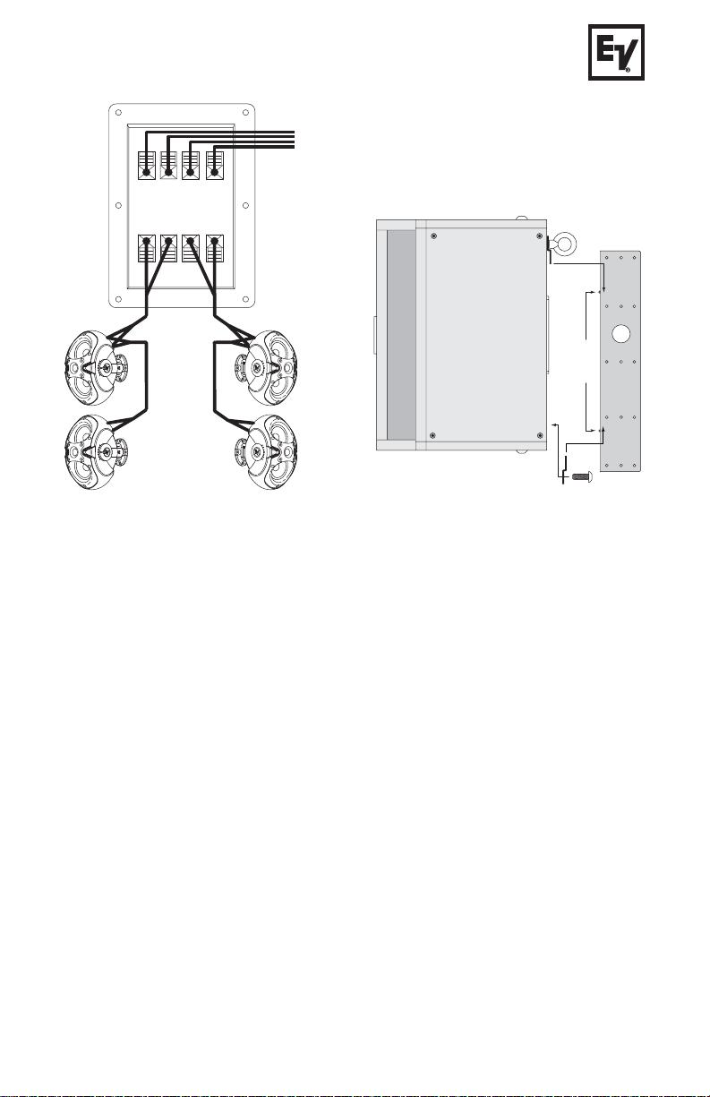
Figure 23: Daisy-Chain Wiring Plan
Figure 24: Corner Mounting
– L +
– L +
– R +
– R +
from
amplifier
Left 1
–
+
–
+
–
+
Right 1
Right 2
Left 2
1
Rungs
3
2
Loading ...
Loading ...
Loading ...