Loading ...
Loading ...
Loading ...
CAUTION
●
When the battery charger has been continuosly
used, the battery charger will be heated, thus
constituting the cause of the failures. Once the
charging has been completed, give 15 minutes
rest until the next charging.
●
If the battery is charged while it is heated
because it has been left for a long time in a
location subject to direct sunlight or because the
battery has just been used, the pilot lamp of the
charger lights for 1 second, does not light for 0.5
seconds (off for 0.5 seconds).
The battery will not be recharged. In such a case,
let the battery cool before charging.
●
When the pilot lamp fl ickers (at 0.2-second
intervals), check for and take out any foreign
objects in the charger’s battery connector. If
there are no foreign objects, it is probable that
the battery or charger is malfunctioning. Take it
to your authorized Service Center.
BEFORE USE
Check the work area to make sure that it is clear of debris
and clutter.
Clear the area of unnecessary personnel. Ensure that
lighting and ventilation is adequate.
OPERATION
1. Installing the bit
Always follow the following procedure to install driver
bit. (Fig. 7)
Driver bit
Hexagonal hole in the anvil
Guide sleeve
Movement
Fig. 7
(1) Pull the guide sleeve forward.
(2) Insert the bit into the hexagonal hole in the anvil.
(3) Release the guide sleeve and it returns to its origianl
position.
CAUTION
If the guide sleeve does not return to its original
position, then the bit is not installed properly.
2. Removing the bit
Please do the opposite point on the method of
installing bit.
3. Confi rm that the battery is mounted correctly.
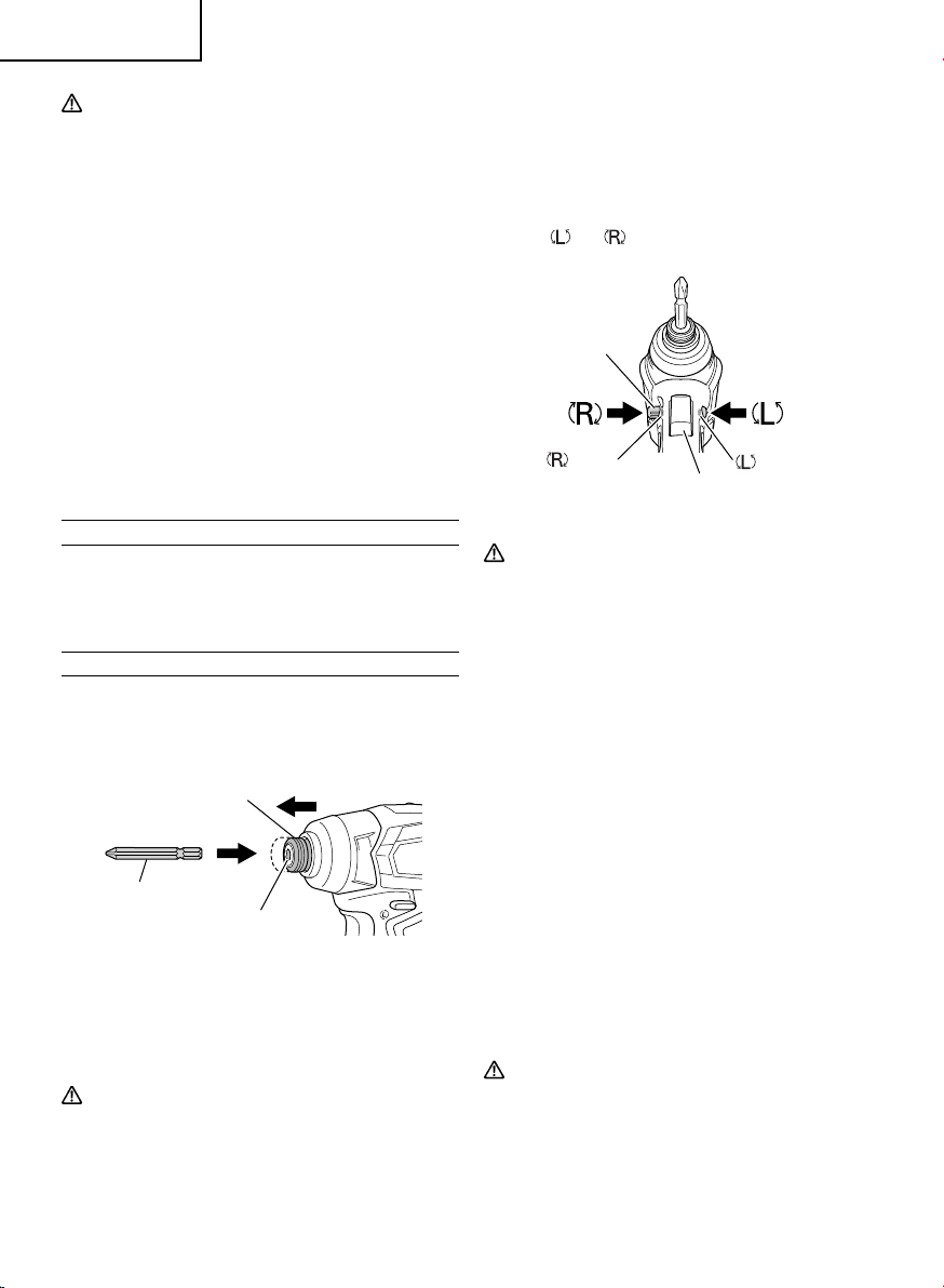
4. Check the rotational direction.
The bit rotates clockwise (viewed from the rear side)
by pushing the R-side of the pushing button.
The L-side of the pushing button is pushed
to turn the bit counterclockwise (See Fig. 8).
(The
and marks are provided on the body.)
push
push
marks
marks
Switch trigger
Pushing button
Fig. 8
CAUTION
The pushing button can not be switched while
the power tool is turning. To switch the pushing
button, stop the power tool, then set the pushing
button.
5. Switch operation
○
When the switch trigger is depressed, the tool rotates.
When the trigger is released, the tool stops.
○
The rotational speed can be controlled by varying
the amount that the switch trigger is pulled. Speed
is low when the switch trigger is pulled slightly and
increases as the switch trigger is pulled more.
○
When releasing the trigger of the switch, the brake will
be applied for immediate stopping.
NOTE
A buzzing noise is produced when the motor is about
to rotate; this is only a noise, not a machine failure.
6. Tightening and loosening screws
Install the bit that matches the screw, line up the bit in
the grooves of the head of the screw, then tighten it.
Push the impact driver just enough to keep the bit
fi tting the head of the screw.
CAUTION
●
Applying the impact driver for too long tightens
the screw too much and can break it.
●
Tightening a screw with the impact driver at an
angle to that screw can damage the head of the
screw and the proper force will not be transmitted
to the screw. Tighten with this impact driver lined
up straight with the screw.
12
English
0000WH18DDXmetabo.indb120000WH18DDXmetabo.indb12 2020/05/2811:33:352020/05/2811:33:35
Loading ...
Loading ...
Loading ...