Loading ...
Loading ...
Loading ...
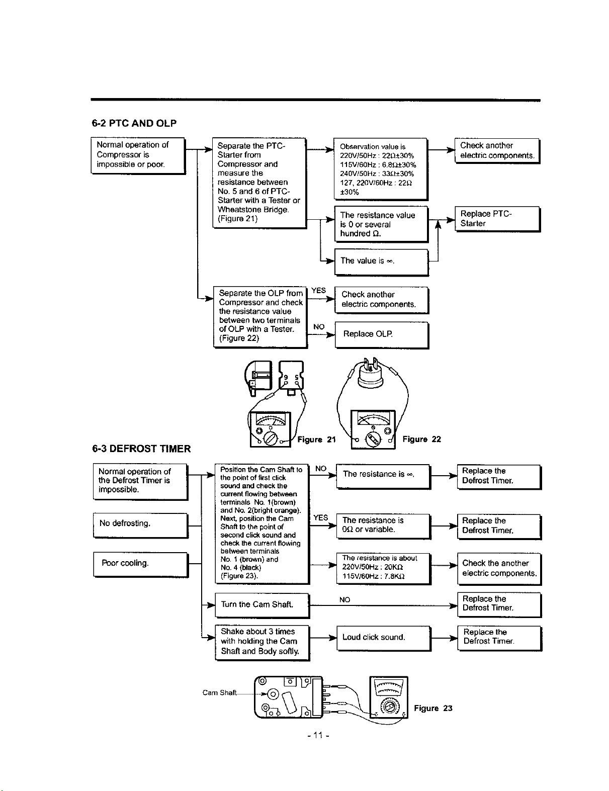
6-2 PTC AND OLP
INormal operationof
Compressor is
impossibleor poor.
6-3 DEFROST TIMER
Separate the PTC-
Sl_rter from
Compressor and
measure the
resistance between
' No. 5 and 6 of PTC-
Starter with a Tester or
Wheatstone Bridge.
(Figure 21)
Observationvalue is
220V/5OHz: 22_:_30%
115V/6OHz ;6.8_.__+30%
240V/50Hz ;33(_±30%
127, 220V/60Hz : 22_
±30%
The resistance value
is 0or several
hundred Q.
The value is _.
Check another
electric components.
Replace OLR
Separate the OLP fmm_ YES_ _
"_' Compressor and check I
the resistance value II
between two terminals I,
of OLP with a Tester. NLN0_
(Figure 22)
.._ Check another I
electric components. I
I
I
(_Figure 21_igure 22
Normal operation of
the Defrost Timer is
impossible.
No defrosting.
Poorcooling.
fl Position the Cam Shaft to
"_ the point of first click
sound and check the
current flowing between
terminals No. t(brown)
and No. 2(bright orange).
FNext, position the Cam
Shaft to the point of
second click sound and
check the current flowing
between terminals
___ No. 1 (brown) and
No. 4 (black)
(Figure 23).
- Turn the Cam Shaft.
Shake about 3 times
"-_ with holding the Cam
Shaft and Body softly.
--_ The resistance is _o.
__The resistance is
OQ or variable.
__The resistance is about
220VISOHz:20K_
1t 5V/6OHz :7.8K3.2
I "°
Loud click sound.
H
-I
Replace the
Defrost Timer.
Replace the I
Defrost Timer.
i
Check the another I
i
electric components. I
Replace the I
Defrost Timer.
Replace the I
Defrost Timer.
-11 -
Figure 23
Loading ...
Loading ...
Loading ...