Loading ...
Loading ...
Loading ...
I
Installation
Instructions
Split
System
Condensers
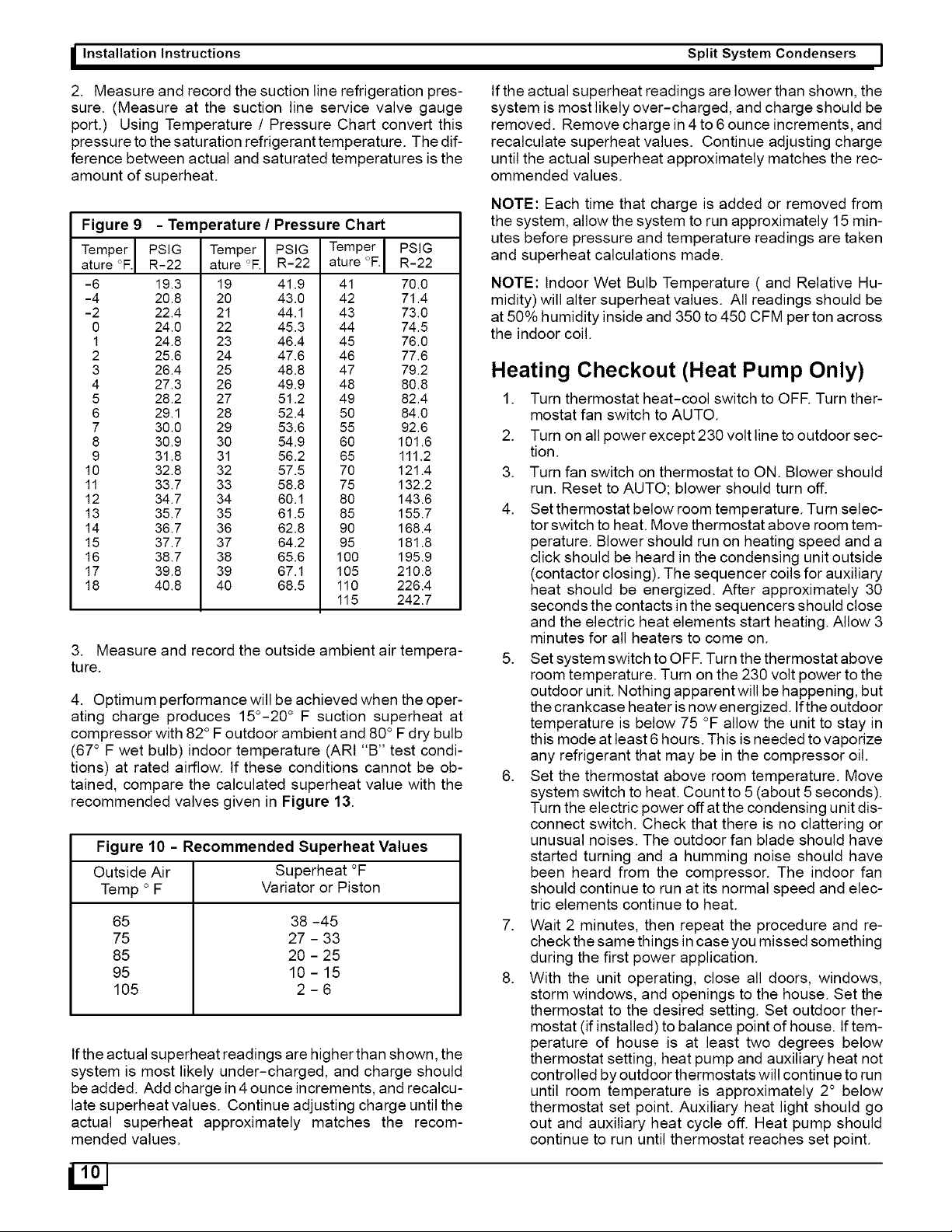
2.
Measure
and
record
the
suction
line
refrigeration
pres-
sure.
(Measure
at
the
suction
line
service
valve
gauge
port.)
Using
Temperature
/
Pressure
Chart
convert
this
pressure
to
the
saturation
refrigerant
temperature.
The
dif-
ference
between
actual
and
saturated
temperatures
is
the
amount
of
superheat.
Figure
9
-
Temperature
/
Pressure
Chart
Temper
|
PSIG
Temper
|
PSIG
|
Temper]
PSIG
ature
°F]
R-22
|
ature
°F.|
R-22
|
ature
°F.)
R-22
-6
19.3
19
419
41
70.0
-4
20.8
20
43.0
42
71.4
-2
22.4
21
441
43
73.0
0
24.0
22
45.3
44
74.5
1
24.8
23
46.4
45
76.0
2
25.6
24
476
46
776
3
26.4
25
48.8
47
79.2
4
27.3
26
49.9
48
80.8
5
28.2
27
51.2
49
82.4
6
29.1
28
52.4
50
84.0
7
30.0
29
53.6
55
92.6
8
30.9
30
54.9
60
101.6
9
31.8
31
56.2
65
111.2
10
32.8
32
57.5
70
121.4
11
33.7
33
58.8
75
132.2
12
34.7
34
60.1
80
143.6
13
35.7
35
61.5
85
155.7
14
36.7
36
62.8
90
168.4
15
37.7
37
64.2
95
181.8
16
38.7
38
65.6
100
195.9
17
39.8
39
67.1
105
210.8
18
40.8
40
68.5
110
226.4
115
242.7
3.
Measure
and
record
the
outside
ambient
air
tempera-
ture.
4.
Optimum
performance
will
be
achieved
when
the
oper-
ating
charge
produces
15°-20°
F
suction
superheat
at
compressor
with
82°
F
outdoor
ambient
and
80°
F
dry
bulb
(67°
F
wet
bulb)
indoor
temperature
(ARI
“B”
test
condi-
tions)
at
rated
airflow.
If
these
conditions
cannot
be
ob-
tained,
compare
the
calculated
superheat
value
with
the
recommended
valves
given
in
Figure
13.
Figure
10
-
Recommended
Superheat
Values
Outside
Air
Superheat
°F
Temp
°
F
Variator
or
Piston
65
38
-45
75
27
-
33
85
20
-
25
95
10-15
105
2-6
if
the
actual
superheat
readings
are
higher
than
shown,
the
system
is
most
likely
under-charged,
and
charge
should
be
added.
Add
charge
in
4
ounce
increments,
and
recalcu-
late
superheat
values.
Continue
adjusting
charge
until
the
actual
superheat
approximately
matches
the
recom-
mended
values.
if
the
actual
superheat
readings
are
lower
than
shown,
the
system
is
most
likely
over-charged,
and
charge
should
be
removed.
Remove
charge
in
4 to
6
ounce
increments,
and
recalculate
superheat
values.
Continue
adjusting
charge
until
the
actual
superheat
approximately
matches
the
rec-
ommended
values.
NOTE:
Each
time
that
charge
is
added
or
removed
from
the
system,
allow
the
system
to
run
approximately
15
min-
utes
before
pressure
and
temperature
readings
are
taken
and
superheat
calculations
made.
NOTE:
Indoor
Wet
Bulb
Temperature
(
and
Relative
Hu-
midity)
will
alter
superheat
values.
All
readings
should
be
at
50%
humidity
inside
and 350
to
450
CFM
per
ton
across
the
indoor
coil.
Heating
Checkout
(Heat
Pump
Only)
1.
Turn
thermostat
heat-cool
switch
to
OFF.
Turn
ther-
mostat
fan
switch
to
AUTO.
2.
Turn
on
all
power
except
230
volt
line
to
outdoor
sec-
tion.
3.
Turn
fan
switch
on
thermostat
to
ON.
Blower
should
run.
Reset
to
AUTO;
blower
should
turn
off.
4.
Setthermostat
below
room
temperature.
Turn
selec-
tor
switch
to
heat.
Move
thermostat
above
room
tem-
perature.
Blower
should
run
on
heating
speed
and
a
click
should
be
heard
in
the
condensing
unit
outside
(contactor
closing).
The
sequencer
coils
for
auxiliary
heat
should
be
energized.
After
approximately
30
seconds
the
contacts
in
the
sequencers
should
close
and
the
electric
heat
elements
start
heating.
Allow
3
minutes
for
all
heaters
to
come
on.
5.
Setsystem
switch
to
OFF.
Turn
the
thermostat
above
room
temperature.
Turn
on
the
230
volt
power
to
the
outdoor
unit.
Nothing
apparent
will
be
happening,
but
the
crankcase
heater
is
now
energized.
If
the
outdoor
temperature
is
below
75
°F
allow
the
unit
to
stay
in
this
mode
at
least
6
hours.
This
is
needed
to
vaporize
any
refrigerant
that
may
be
in
the
compressor
oil.
6.
Set
the
thermostat
above
room
temperature.
Move
system
switch
to
heat.
Count
to
5
(about
5
seconds).
Turn
the
electric
power
off
at
the
condensing
unit
dis-
connect
switch.
Check
that
there
is
no
clattering
or
unusual
noises.
The
outdoor
fan
blade
should
have
started turning
and
a
humming
noise
should
have
been
heard
from
the
compressor.
The
indoor
fan
should
continue
to
run
at
its
normal
speed
and
elec-
tric
elements
continue
to
heat.
7.
Wait
2
minutes,
then
repeat
the
procedure
and
re-
check
the
same
things
in
case
you
missed
something
during
the
first
power
application.
8.
With
the
unit
operating,
close
all
doors,
windows,
storm
windows,
and
openings
to
the
house.
Set
the
thermostat
to
the
desired
setting.
Set
outdoor
ther-
mostat
(if
installed)
to
balance
point
of
house.
If
tem-
perature
of
house
is
at
least
two
degrees
below
thermostat
setting,
heat
pump
and
auxiliary
heat
not
controlled
by
outdoor
thermostats
will
continue
to
run
until
room
temperature
is
approximately
2°
below
thermostat
set
point.
Auxiliary
heat
light
should
go
out
and
auxiliary
heat
cycle
off.
Heat
pump
should
continue
to
run
until
thermostat
reaches
set
point.
|
Loading ...
Loading ...
Loading ...