Installation
Instructions
SPLIT
SYSTEM
Premium
Line
AC
&
HP
CONDENSERS
Save
This
Manual
for
Future
Reference
Dec.
2004
I
Installation
Instructions
Split
System
Condensers
Installation/
Startup
Information
These
instructions
must
be
read
and
understood
completely
before
attempting
installation.
Installation
or
repairs
made
by
unqualified
persons
can
result
in
hazards
to
you and
others.
Installation
MUST
conform
with
local
building
codes
or,
in
the
absence
of
local
codes,
with
the
the
National
Electrical
Code
NFPA
70/ANSI
C1-1999
or
current
edition
and
Canadian
Electrical
Code
Part
1
CSA
C.22.1.
The
information
contained
in
this
manual
is
intended
for
use
by
a
qualified
service
technician
familiar
with
safety
procedures
and
equipped
with
the
proper
tools
and
test
instruments.
Failure
to
carefully
read
and
follow
all
instruc-
tions
in
this
manual
can
result
in
equipment
malfunction,
property
damage,
personal
injury
and/or
death.
After
uncrating
unit,
inspect
thoroughly
for
hidden
damage.
If
damage
is
found,
notify
the
transportation
company
im-
mediately
and
file
a
concealed
damage
claim.
CAUTION
Improper
installation,
adjustment,
alteration,
service
or
maintenance
can
void
the
warranty.
The
weight
of
the
condensing
unit
requires
caution and
proper
handling
procedures
when
lifting
or
moving
to
avoid
personal
injury.
Use
care
to
avoid
contact
with
sharp
or
pointed
edges.
Safety
Precautions
1.
Always
wear
safety
eye
wear
and
work
gloves
when
installing
equipment.
2.
Never
assume
electrical
power
is
disconnected.
Check
with
meter
and
disconnect.
3.
Keep
hands
out
of
fan
areas
when
power
is
connected
to
equipment.
4.
R-22
causes
frost-bite
burns.
5.
R-22
is
toxic
when
burned.
NOTE
TO
INSTALLING
DEALER:
The
Owners
Instruc-
tions
and
Warranty
are
to
be
given
to
the
owner
or
promi-
nently
displayed
near
the
indoor
Furnace/Air
Handler
Unit.
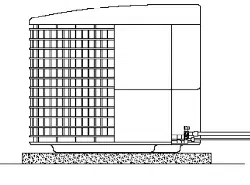
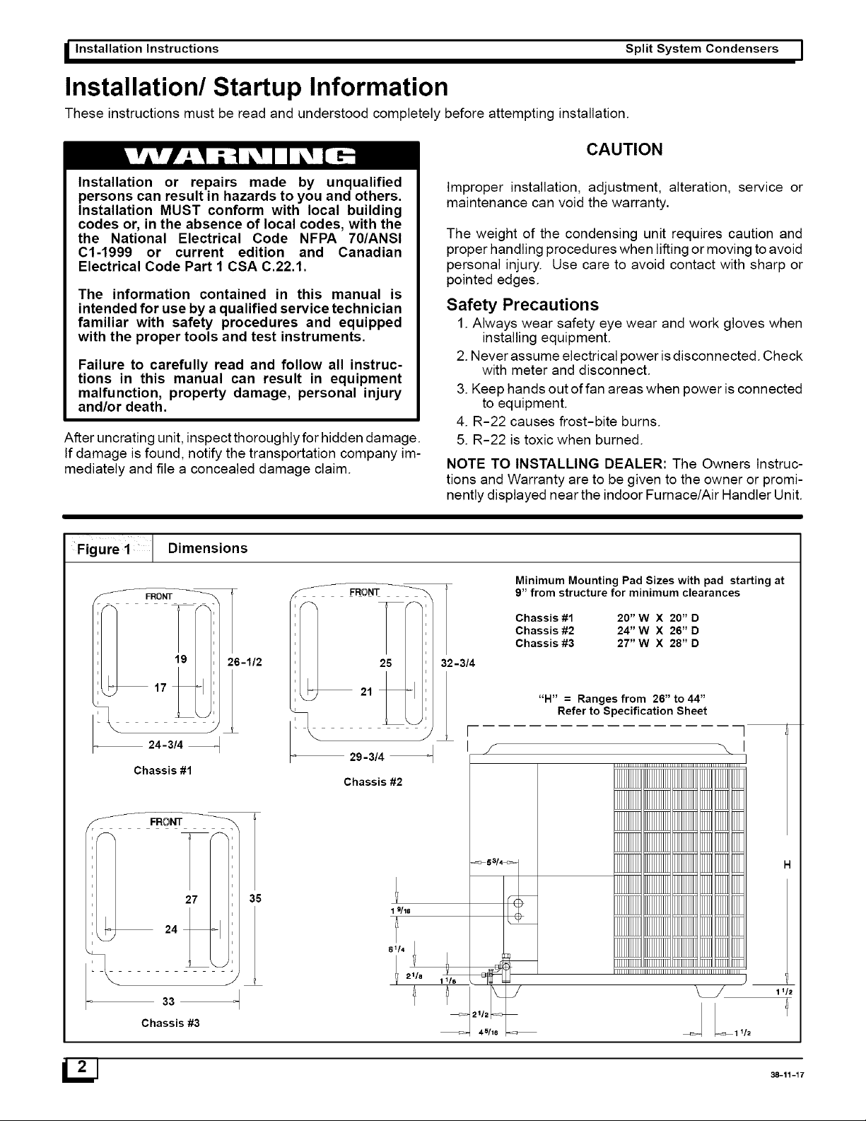
Dimensions
Figure
1
Chassis
#2
alla
Chassis
#3
—
29-314
——+
ie
JL!
Minimum
Mounting
Pad
Sizes
with
pad
starting
at
9”
from
structure
for
minimum
clearances
Chassis
#1
20”
W
X
20”D
Chassis
#2
24"
W
X
26”D
Chassis
#3
27”
W
X
28"D
“H”
=
Ranges
from
26”
to
44”
Refer
to
Specification
Sheet
itle
aife
38-11-17
|
Split
System
Condensers
Installation
Instructions
J
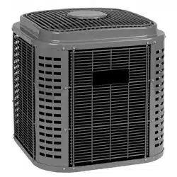
Locating
The
Outdoor
Unit:
Check
local
codes
covering
zoning,
noise,
platforms.
if
practical,
avoid
locating
next
to
fresh
air
intakes,
vent
or
bedroom
windows.
Noise
may
carry
into
the
openings
and
disturb
people
inside.
Placement
of
the
unit
should
be
in
a
well
drained
area
or
unit
must
be
supported
high
enough
so
runoff
will
not
enter
the
unit.
Do
not
locate
where
heat,
lint
or
exhaust
fumes
will
be
dis-
charged
on
unit
(as
from
dryer
vents).
Clearances:
Roof
top
installations
are
acceptable
providing
the
roof
will
support
the
unit
and
provisions
are
made
for
water
drain-
age
and
the
noise
or
vibration
through
the
structure.
Do
not
install
the
unit
in
a
recessed
or
confined
area
where
recirculation
of
discharge
air
may
occur.
Heat
Pumps
Only:
The
top
surface
of
platform
must
be
above average
winter
snow
levels
to
prevent
coil
blockage.
Nominal
operating
clearances,
where
practical,
are
48
inches
(120
cm)
above
unit
for
discharge
air
and
18
inches
(40cm)
around
coil
for
intake
air
on
three
sides.
Clearance
on
one
side
(normally
between
unit
and
structure)
may
be
reduced
to
6
inches
(15cm).
Nominal
clearances
are
based
from
a
solid
parallel
object,
wall,
roof
overhang,
etc.
Do
Not
install
under
roof
overhangs
without
guttering.
A
minimum
vertical
clearance
of
48”
is
required
to
overhang.
The
clearance
may
be
reduced
from
a
single
object
with
a
small
surface
area,
such
as
the
end
of
a
wall,
outside
cor-
ner
of
a
wall,
fence
section
or
a
post,
etc.
As
a
general
rule
the
width
of
the
object
should
equal
the
minimum
clearance
from
the
unit.
For
example,
a
4
inch
(10cm)
fence
post
could
be
4
inches
(10cm)
from
the
unit.
Unit
Support:
Inside
corner
locations
on
single
story
structures
require
evaluation.
Large
overhanging
soffits
may
cause
air
recir-
culation
in
a
corner
area
even
though
recommended
clear-
ances
are
maintained.
As
a
guide
locate
the
unit
far
enough
out
so
that half
of
the
discharge
grille
is
out
from
under
the
soffit.
Two
or
more
units
may
be
spaced
with
18
inches
(45cm)
between
units.
A
service
clearance
of
24
inches
(60cm)
is
desirable
from
control
box
end
or
side.
Control
box
and
corner
panel
be-
low
it
can
be
loosened
and
moved
out
to
the
side
to
facili-
tate
servicing.
Internal
components
can
be
accessed
through
control
box
corner
or
top
only.
The
unit
must
be
level,
and
supported
above
grade
by
beams,
platform
or
a
pad.
Platform
or
pad
can
be
of
open
or
solid
construction
but
should
be
of
permanent
materials
such
as
concrete,
bricks,
blocks,
steel
or
pressure
treated
timbers
approved
for
ground
contact.
Refer
to
Unit
Clear-
ances
to
help
determine
size
of
supports
etc. Soil
condi-
tions
should
be
considered
so
the
platform
or
pad
does
not
shift
or
settle
excessively
and
leave
the
unit
only
partially
supported.
CAUTION
Inadequate
support
could
cause
excessive
vibration
and
noise
or
binding
and
stress
on
refrigerant
lines
resulting
in
equipment
failure.
To
minimize
vibration
or
noise
transmission,
it
is
recom-
mended
that
supports
not
be
in
contact
with
the
building
structure.
However,
slabs
on
grade constructions
with
an
extended
pad
are
normally
acceptable.
A.
Ground
Level
Installation:
if
beams
or
an
open
platform
are
used
for
support
it
is
rec-
ommended
that
the
soil
be
treated
or
area
be
graveled
to
retard
the
growth
of
grasses
and
weeds.
B.
Roof
Top
Installation:
This
type
of
installation
is
not
recommended
on
wood
frame
structures
where
low
noise
levels
are
required.
Supporting
structure
or
platform
for
the
unit
must
be
level.
If
installation
is
on
a
flat
roof
the
unit
should
be
4
inches
(10cm.)
above
roof
level.
Four
by
four
posts
placed
over
a
load
bearing
wall
make
a
suitable
mounting
platform.
If
possible,
place
the
unit
over
one
or
more
load
bearing
walls.
If
there
are
several
units,
mount
them
on
platforms
that
are
self-supporting
and
span
load
bearing
walls.
These
suggestions
are
to
minimize
noise
and
vibration
transmission
through
the
structure.
If
the
structure
is
a
home
or
apartment,
avoid
(if
practical)
locating
the
unit
over
bedrooms
or
study.
NOTE:
When
condensing
unit
is
to
be
installed
on
a
bonded
guaranteed
roof,
a
release
must
be
obtained
from
the
building
owner
to
free
the
installer
from
all
liabilities.
[3]
Installation
Instructions
Split
System
Condensers
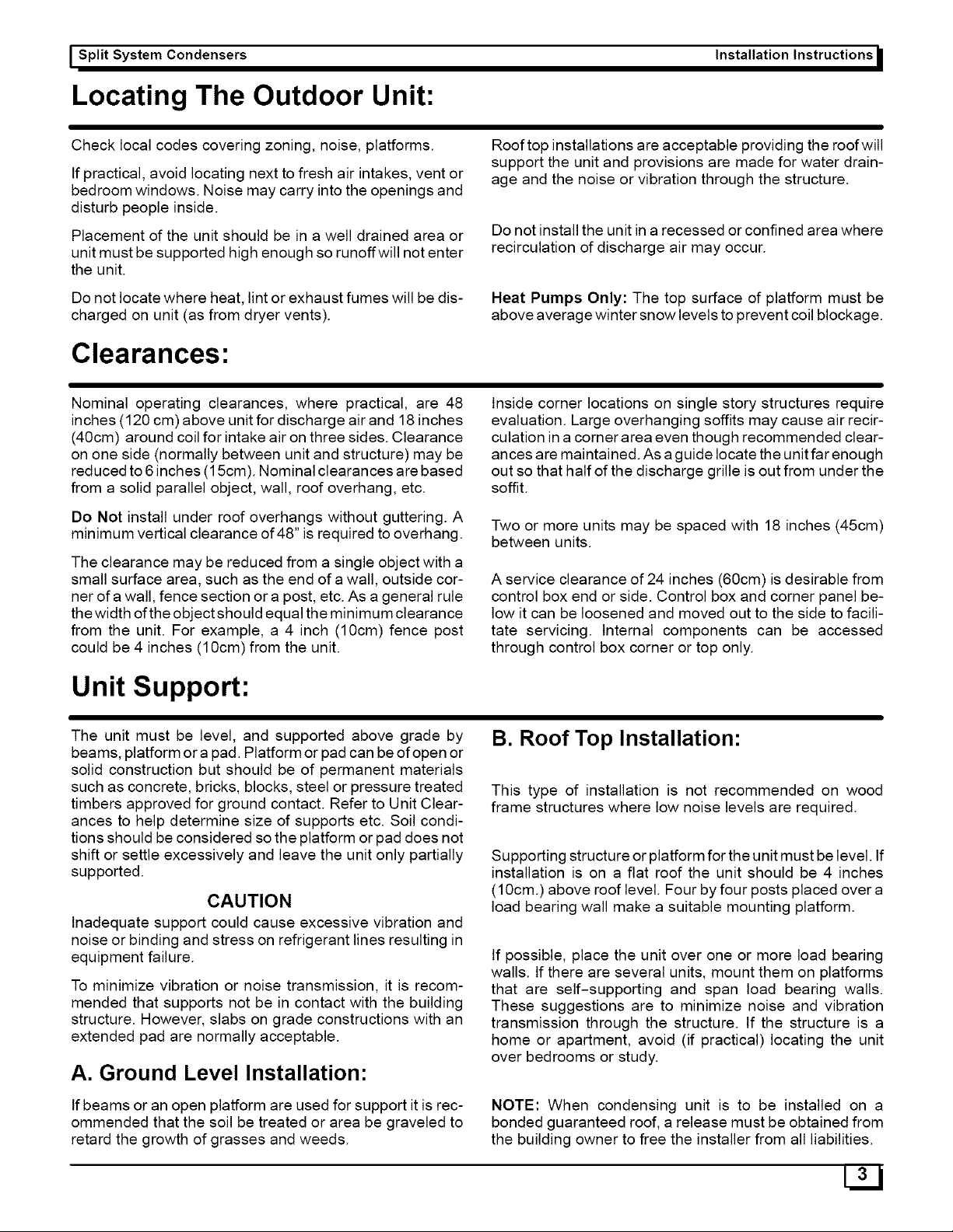
Figure
2
Clearances
Recommended
Clearances
24”
Minimum
Clearances
24”
Minimum
Clearances
Minimum
Clearances
24”
24”
Split
System
Condensers
Installation
Instructions
installing
Refrigerant
Lines
Component
Matches
Check
to
see
that
you
have
the
proper
system
compo-
nents.
APPROVED
MATCHED
SYSTEM
COMPONENTS
MUST
BE
USED.
Refer
to
the
Sales
Specification
Sheet
or
Split
System
Summary
for
match
data
and
orifice
sizes.
The
outdoor
units
are
shipped
with
a
refrigerant
charge
to
match
the
indoor
unit
and
25
ft.
(7.5m)
of
refrigerant
line.
If
shorter
or
longer
lines
are
used,
the
charge
will
have
to
be
adjusted.
OUR
STANDARD
RECOMMENDED
REFRIGERANT
LINE
LENGTH
IS
75
ft.
WITH
A
MAXIMUM
VERTICAL
SEPARATION
OF
50
ft.
BETWEEN
THE
OUTDOOR
AND
INDOOR
UNITS
WITH
3
TRAPS,
2
TRAPS
FOR
40
FOOT
RISE.
LONGER
REFRIGERANT
LINES
CAN
BE
INSTALLED
BY
USING
THE
EXTENDED
LENGTH
RE-
FRIGERANT
PIPING
MANUAL
#42106111400
WITH
PRIOR
APPROVAL
FROM
ICP
TECHNICAL
SERVICE
DEPARTMENT.
Restrictor
Orifice
Some
indoor
matches
use
a
restrictor
orifice
in
the
fitting
at
the
indoor
coil.
Some
matches
may
require
a
different
ori-
fice
for
proper
system
performance
and
it
must
be
changed
before
the
refrigerant
lines
are
connected.
Changing
the
Restrictor
Orifice
The
restrictor
orifice
is
located
in
a
fitting
in
the
liquid
line.
The
fitting
is
actually
the
distributor
end
of
the
cap
tube
as-
sembly.
1.
Remove
the
liquid
line
fitting
and replace
restrictor
ori-
fice.
(STANDARD
RIGHT
HAND
THREAD)
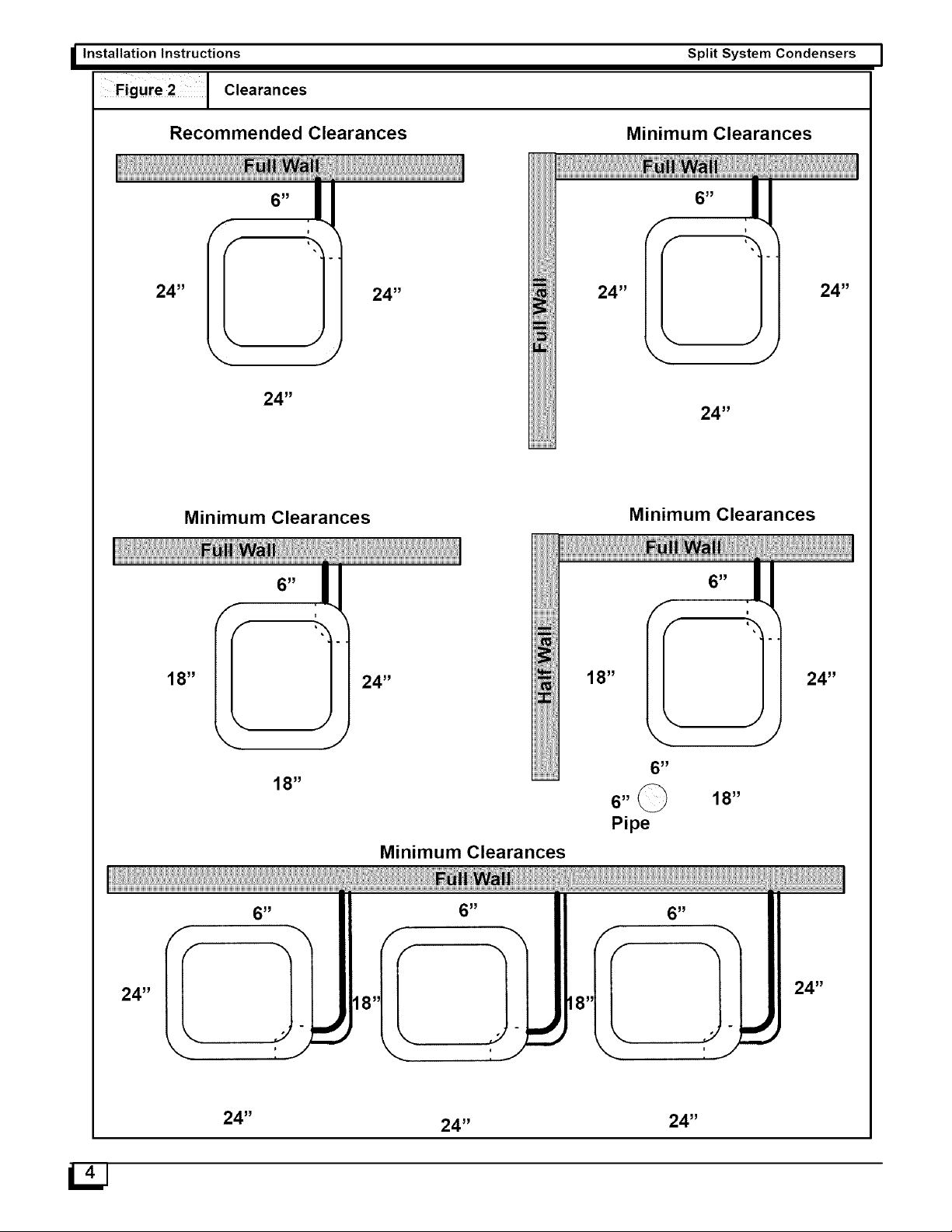
2.
Make
sure
the
restrictor
is
installed
with
the
rounded
end
toward
the
feeder
tubes.
See
Figure
3.
Figure
3
Restrictor
Orifice
Nut
and
Liquid
Line
with
Strainer
Restrictor
Orifice
co
Rounded
End
Feeder
Tubes
Refrigeration
Line
Sets
Ifitis
necessary
to
add
tubing
in
the
field,
use
dehydrated
or
dry
sealed
deoxidized
copper
refrigeration
tube.
DO
NOT
use
copper
water
pipe.
Itis
important
that
no
tubing
is
cut
or
seals
broken
until
you
are
ready
to
actually
make
connections
to
the
evaporator
and
to
the
condenser
section.
Do
not
remove
rubber
plugs
or
copper
caps
from
the
tube
ends
until
ready
to
make
connections
at
evapora-
tor
and
condenser.
PLEASE!
UNDER
NO
CIRCUMSTANCES
LEAVE
THE
LINES
OPEN
TO
THE
ATMOSPHERE
FOR
ANY
PERIOD
OF
TIME.
Be
extra careful
with
sharp
bends.
This
tubing
can
kink”
very
easily,
and
if
this
occurs,
the
entire
tube length
will
have
to
be
replaced.
Extra
care
at
this
time
will
eliminate
future
service
problems.
Suspension
And
Installation
Of
Refrigeration
Lines
DO
NOT
fasten
liquid
or
suction
lines
in
direct
contact
with
the floor
or
ceiling
joist.
Use
an
insulated
or
suspension
type
of
hanger.
Keep
both
lines
separate,
and
insulate
the
suction
line.
Both
lines
should
be
insulated
in
extremely
long
runs
in
an
attic
or
underground
in
a
raceway,
50’
or
more.
I
Installation
Instructions
Split
System
Condensers
Do
not
let
refrigerant
lines
come
in
direct
contact
with
foundation.
When
running
refrigerant
lines
through
the
foundation
or
wall,
the
openings
should
be
made
large
enough
to
allow
for
a
sound
absorbing
material
to
be
placed
or
installed
between
the
tubing
and
the
foundation.
This
will
prevent
noise
transmission
between
the
tubing
and
the
wall
section
(foundation)
or
the
building.
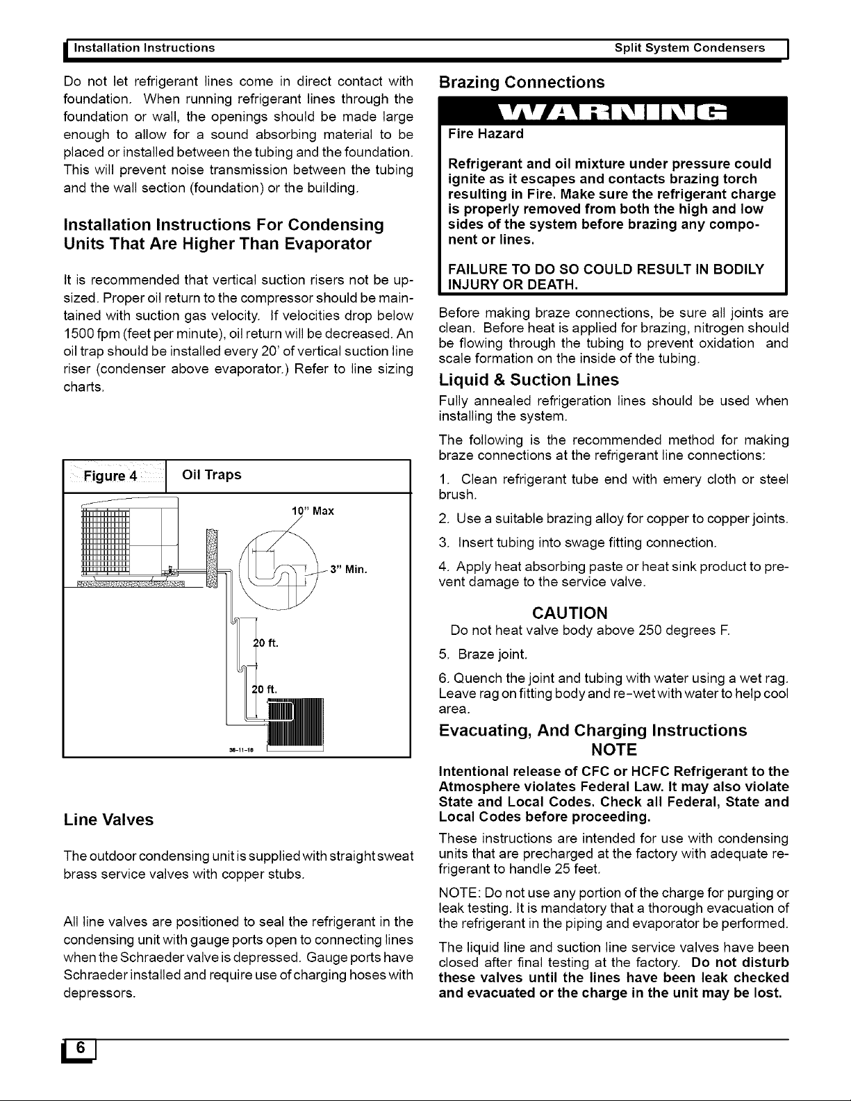
Installation
Instructions
For
Condensing
Units
That
Are
Higher
Than
Evaporator
It
is
recommended
that
vertical
suction
risers
not
be
up-
sized.
Proper
oil
return
to
the
compressor
should
be
main-
tained
with
suction
gas
velocity.
If
velocities
drop
below
1500
fom
(feet
per
minute),
oil
return
will
be
decreased.
An
oil
trap
should
be
installed
every
20’
of
vertical
suction
line
riser
(condenser
above
evaporator.)
Refer
to
line
sizing
charts.
Oil
Traps
Figure
4
Line
Valves
The
outdoor
condensing
unit
is
supplied
with
straight
sweat
brass
service
valves
with
copper
stubs.
All
line
valves
are
positioned
to
seal
the
refrigerant
in
the
condensing
unit
with
gauge
ports
open
to
connecting
lines
when
the
Schraeder
valve
is
depressed.
Gauge
ports
have
Schraeder
installed
and
require
use
of
charging
hoses
with
depressors.
Brazing
Connections
Fire
Hazard
Refrigerant
and
oil
mixture
under
pressure
could
ignite
as
it
escapes
and
contacts
brazing
torch
resulting
in
Fire.
Make
sure
the
refrigerant
charge
is
properly
removed
from
both
the
high
and
low
sides
of
the
system
before
brazing
any
compo-
nent
or
lines.
FAILURE
TO
DO SO
COULD
RESULT
IN
BODILY
INJURY
OR
DEATH.
Before
making
braze
connections,
be
sure
all
joints
are
clean.
Before
heat
is
applied
for
brazing,
nitrogen
should
be
flowing
through
the
tubing
to
prevent
oxidation
and
scale
formation
on
the
inside
of
the
tubing.
Liquid
&
Suction
Lines
Fully
annealed
refrigeration
lines
should
be
used
when
installing
the
system.
The
following
is
the
recommended
method
for
making
braze
connections
at
the
refrigerant
line
connections:
1.
Clean
refrigerant tube
end
with
emery
cloth
or
steel
brush.
2.
Use
a
suitable
brazing
alloy
for
copper
to
copper
joints.
3.
Insert
tubing
into
swage
fitting
connection.
4.
Apply
heat
absorbing
paste
or
heat
sink
product
to
pre-
vent
damage
to
the
service
valve.
CAUTION
Do
not
heat
valve
body
above
250
degrees
F.
5.
Braze
joint.
6.
Quench
the
joint
and
tubing
with
water
using
a
wet
rag.
Leave
rag
on
fitting
body
and
re-wet
with
water
to
help
cool
area.
Evacuating,
And
Charging
Instructions
NOTE
Intentional
release
of
CFC
or
HCFC
Refrigerant
to
the
Atmosphere
violates
Federal
Law.
It
may
also
violate
State
and
Local
Codes.
Check
all
Federal,
State
and
Local
Codes
before
proceeding.
These
instructions
are
intended
for
use
with
condensing
units
that
are
precharged
at
the
factory
with
adequate
re-
frigerant
to
handle
25
feet.
NOTE:
Do
not
use
any
portion
of
the
charge
for
purging
or
leak
testing.
It
is
mandatory
that
a
thorough
evacuation
of
the
refrigerant
in
the
piping
and
evaporator
be
performed.
The
liquid
line
and
suction
line
service
valves
have
been
closed
after
final
testing
at
the
factory.
Do
not
disturb
these
vaives
until
the lines
have
been
leak
checked
and
evacuated
or
the
charge
in
the
unit
may
be
lost.
Le

|
Split
System
Condensers
Installation
Instructions
J
Recommended
Method
Of
Evacuating
A
System
1.
Connect
the
vacuum
pump
to
the
suction
and
liquid
line
gauge
ports.
2.
If
the
evacuation
is
being
performed
on
a
new
system
installation,
the
valves
should
be
kept
in
the
"front
seated”
(closed)
position.
This
will
allow
the
mechanic
to
evacuate
the
refrigeration
lines
and
the
indoor
coil,
without
disturbing
the
factory
charge
in
the
outdoor
unit.
3.
Follow
the
vacuum
pump
manufacturer’s
instructions.
Allow
the
pump
to
operate
until
the
system
has
been
eva-
cuated
down
to
300
microns.
Allow
the
pump
to
continue
running
for
an
additional
15
minutes.
Turn
off
the
pump
and
leave
the
connections
secured
to
the
two
service
valves.
After
5
minutes,
if
the
system
fails
to
hold
500
microns
or
less,
check
all
connections
for
tight
fit
and
repeat
the
evac-
uation
procedure.
4.
Isolate
the
vacuum
pump
from
the
system
by
closing
the
shutoff
valves
on
the
gauge
bar.
Disconnect
the
vacuum
pump.
Valve
Actuation:
Service
Valves
Remove
the
service
valve
cap,
if
there
is
a
male
valve
stem
see
instructions
for
Ball
Valves.
For
the
standard
service
valve
there
are
two
variations,
but
both
have
internal
stems.
The
first
style
uses
an
internal
snap
ring
to
retain
the
valve
stem
and
the
second
has
a
rolled
top
and
also
has
finer
threads
on
the
valve
cap.
NOTE:
You
may
encounter
more
than
one
type
of
valve
on
a
unit.
For
service
valves
fully
insert
a
hex
wrench
into
the
stem.
A
back-up
wrench
is
required
on
the
valve
body
to
open
the
valve
stem.
Backout
counterclockwise
until
the
valve
stem
stops
or
just
touches
the
retaining
ring.
NOTE:
THIS
IS
NOT
A
BACKSEATING
VALVE.
For
valves
with
retainer
rings
care
must
be
taken
to
prevent
dislodging
them
when
opening
valve.
Electrical
Wiring
The
service
valve
cap
is
a
primary
seal
for
the
valve
and
must
be
properly
tightened
to
prevent
leaks.
Make
sure
cap
is
clean
and
apply
refrigerant
oil
to
threads
and
sealing
sur-
face
of
cap.
For
valves
with
retaining
rings:
Replace
service
valve
cap
and
torque
to;
8-11
ft.
Ibs.
on
1/4”
and
3/8”
valves,
12-16
ft.
lbs.
on
5/8”
and
3/4”,
15-21
ft.
los
on
7/8”
valves.
If
torque
wrench
is
not
available,
tighten
cap
finger
tight
and
then
tighten
one
(1)
additional
wrench
flat
or
1/6
of
a
turn.
For
valves
with
rolled
tops:
Replace
service
valve
cap
tighten
cap
finger
tight
and
then
tighten
one
(1)
additional
wrench
flat
or
1/6
of
a
turn
to
properly
seat
the
sealing
sur-
faces.
Subsequent
installations
will
seat
with
1/2
to
1
wrench
flat
of
turning.
Gauge
Ports:
All
Valves
Check
for
leaks
at
the
schrader
port
and
tighten
valve
core
if
necessary.
Install
plastic
caps
finger
tight.
Ball
Valves
On
models
with
ball
type
valves
use
a
6”
crescent
wrench
to
rotate
the
valve
stem
90°
counter
clockwise.
Retighten
valve
cap
to
6-8
ft.
lbs.
If
torque
wrench
is
not
available,
tighten
cap
finger
tight
and
then
tighten
one
(1/2)
additional
wrench
flat.
REFRIGERATION
PIPING
&
CHARGING
For
extended
piping
over
the
recommended
75
feet
please
refer
to
Extended
Length
Refrigerant
Piping
Manual
(Part#
42106111400).
Electrical
Shock
Hazard.
Shut
off
electric
power
at
fuse
box
or
service
pan-
el
before
making
any
electrical
connections.
Failure
to
shut
off
electric
power
can
result
in,
property
damage,
personal
injury
and/or
death.
The
supply
voltage
should
be
208-230
volts
(196
volt
mini-
mum
to
253
volts
maximum)
60Hz
single
phase.
APPROVED
FOR
USE
WITH
COPPER
CONDUCTORS
ONLY.
DO
NOT
USE
ALUMINUM
WIRE.
REFER
TO
UNIT
RATING
PLATE
FOR
CIRCUIT
PROTECTION.
Grounding
Permanently
ground
unit
in
accordance
with
the
National
Electrical
Code
and
local
codes
or
ordinances.
Use
a
cop-
per
conductor
of
the
correct
size
from
the
grounding
termi-
nal
in
control
box
to
a
grounded
connection
in
the
service
panel
ora
properly
driven
and
electrically
grounded
ground
rod.
Wiring
Connections
Make
all
outdoor
electrical
supply
(Line
Voltage)
connec-
tions
with
raintight
conduit
and
fittings.
Most
codes
require
a
disconnect
switch
outdoors
within
sight
of
the
unit.
Route
Line
Voltage
wiring
through
hole
in
the
bottom
of
the
Control
Box
and
around
the
side
of
the
shelf
to
connect
to
Contactor
and
Ground
Lug.
Route
Low
Voltage
wiring
through
entrance
in
bottom
of
control
box and
make
ALL
low
voltage
connections
to
the
low
voltage
pigtails
in
the
area
created
by
the
shelf
and
the
low-volt
shield.
(Two
Yellow
wires,
AC
or
W,Y,O,BL,
&R
for
HP).
The
pigtail
wires
have
600V
insulation
meeting
ap-
proval
for
use
in
high
voltage
areas.
27]
Installation
Instructions
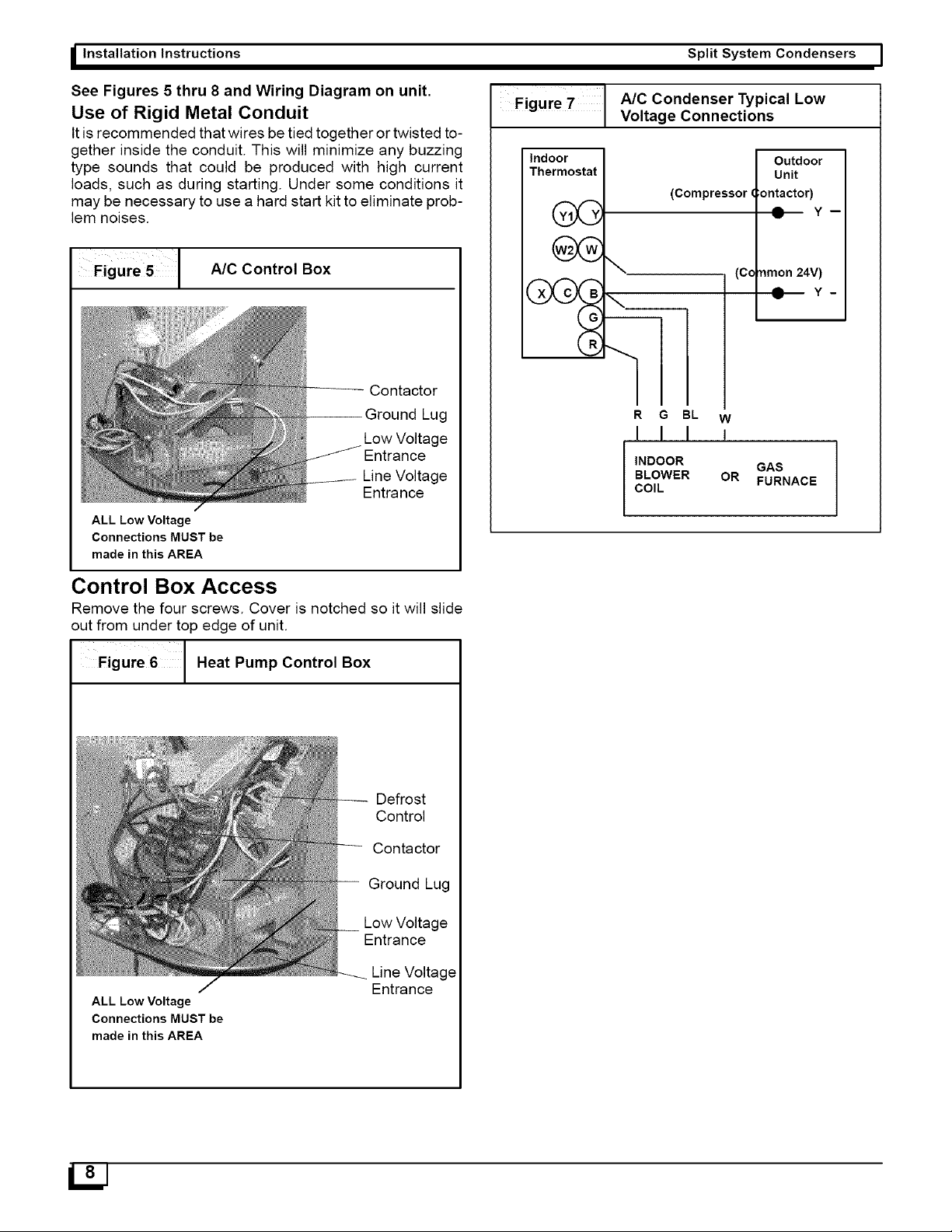
See
Figures
5
thru
8
and
Wiring
Diagram
on
unit.
Use
of
Rigid
Metal
Conduit
It
is
recommended
that
wires
be
tied
together
or
twisted
to-
gether
inside
the
conduit.
This
will
minimize
any
buzzing
type
sounds
that
could
be
produced
with
high
current
loads,
such
as
during
starting.
Under
some
conditions
it
may
be
necessary
to
use
a
hard
start
kit
to
eliminate
prob-
lem
noises.
Figure
5
A/C
Control
Box
Contactor
Ground
Lug
Low
Voltage
Entrance
Line
Voltage
Entrance
ALL Low
Voltage
Connections
MUST
be
made
in
this
AREA
Control
Box
Access
Remove
the
four
screws.
Cover
is
notched
so
it
will
slide
out
from
under
top
edge
of
unit.
Figure
6
Heat
Pump
Control
Box
Defrost
Control
Contactor
Ground
Lug
Low
Voltage
Entrance
Line
Voltage
Entrance
ALL Low
Voltage
Connections
MUST
be
made
in
this
AREA
Split
System
Condensers
Figure
7
AIC
Condenser
Typical
Low
Voltage
Connections
Indoor
Outdoor
Thermostat
Unit
(Compressor
Gontactor)
vik
Y,
@—
Y-
»*
(Common
24V)
XA
CAB
@—
Y-
R
R
G
BL
w
{|
J J
INDOOR
GAS
BLOWER
OR
COIL
FURNACE
|
Split
System
Condensers
Installation
Instructions
J
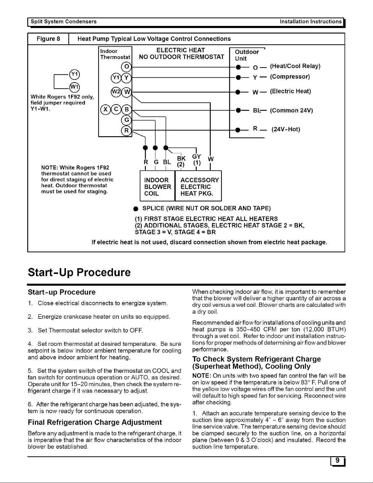
Figure
8
Heat
Pump
Typical
Low
Voltage
Control
Connections
Indoor
ELECTRIC
HEAT
Outdoor
—
Thermostat}
NO
OUTDOOR
THERMOSTAT
|
Unit
Oo
@—
0
—
(Heat/Cool
Relay)
@)
Y1Y
Y
@—
Y
—
(Compressor)
@)
2
@—
wW—
(Electric
Heat)
White
Rogers
1F92
only,
IN
field
jumper
required
Y1-W1.
XXCXB
@—
BI—
(Common
24V)
G
R
@— R—
(24V-Hot)
ital
BL
1
NOTE:
White
Rogers
1F92
|
(2)
(
|
thermostat
cannot
be
used
for
direct
staging
of
electric
INDOOR
ACCESSORY
heat.
Outdoor
thermostat
BLOWER
ELECTRIC
must
be
used
for
staging.
COIL
HEAT
PKG.
@
SPLICE
(WIRE
NUT
OR
SOLDER
AND
TAPE)
(1)
FIRST
STAGE
ELECTRIC
HEAT
ALL
HEATERS
(2)
ADDITIONAL
STAGES,
ELECTRIC
HEAT
STAGE
2 =
BK,
STAGE
3 =
V,
STAGE
4=BR
If
electric
heat
is
not
used,
discard
connection
shown
from
electric
heat
package.
Start-Up
Procedure
Start-up
Procedure
1.
Close
electrical
disconnects
to
energize
system.
2.
Energize
crankcase
heater
on
units
so
equipped.
3.
Set
Thermostat
selector
switch
to
OFF.
4.
Set
room
thermostat
at
desired
temperature.
Be
sure
setpoint
is
below
indoor
ambient
temperature
for
cooling
and
above
indoor
ambient
for
heating.
5.
Set
the
system
switch
of
the
thermostat
on
COOL
and
fan
switch
for
continuous
operation
or
AUTO,
as
desired.
Operate
unit
for
15-20
minutes,
then
check
the
system
re-
frigerant
charge
if
it
was
necessary
to
adjust.
6.
After
the
refrigerant
charge
has
been
adjusted,
the
sys-
tem
is
now
ready
for
continuous
operation.
Final
Refrigeration
Charge
Adjustment
Before
any
adjustment
is
made
to
the
refrigerant
charge,
it
is
imperative
that
the
air
flow
characteristics
of
the
indoor
blower
be
established.
When
checking
indoor
air
flow,
it
is
important
to
remember
that
the
blower
will
deliver
a
higher
quantity
of
air
across
a
dry
coil
versus
a
wet
coil.
Blower
charts
are
calculated
with
a
dry
coil.
Recommended
air
flow
for
installations
of
cooling
units
and
heat
pumps
is
350-450
CFM
per
ton
(12,000
BTUH)
through
a
wet
coil.
Refer
to
indoor
unit
installation
instruc-
tions
for
proper
methods
of
determining
air
flow
and
blower
performance.
To
Check
System
Refrigerant
Charge
(Superheat
Method),
Cooling
Only
NOTE:
On
units
with
two
speed
fan
control
the fan
will
be
on
low
speed
if
the
temperature
is
below
83°
F.
Pull
one
of
the
yellow
low
voltage
wires
off
the fan
control
and
the
unit
will
default
to
high
speed
fan
for
servicing.
Reconnect
wire
after
checking.
1.
Attach
an
accurate
temperature
sensing
device
to
the
suction
line
approximately
4”
-
6”
away
from
the
suction
line
service
valve.
The
temperature
sensing
device
should
be
clamped
securely
to
the
suction
line,
on
a
horizontal
plane
(between
9
&
3
O'clock)
and
insulated.
Record
the
suction
line
temperature.
Lo]
I
Installation
Instructions
Split
System
Condensers
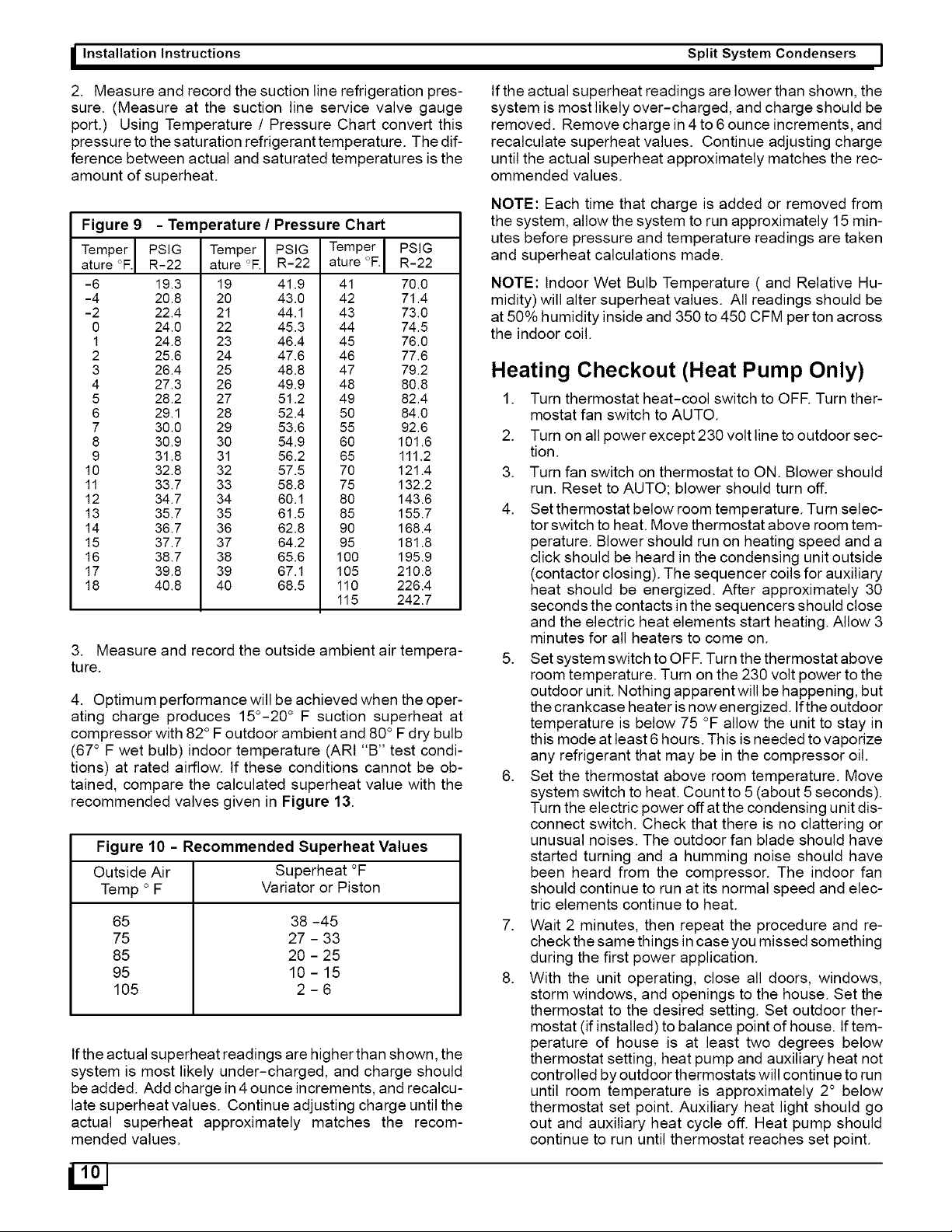
2.
Measure
and
record
the
suction
line
refrigeration
pres-
sure.
(Measure
at
the
suction
line
service
valve
gauge
port.)
Using
Temperature
/
Pressure
Chart
convert
this
pressure
to
the
saturation
refrigerant
temperature.
The
dif-
ference
between
actual
and
saturated
temperatures
is
the
amount
of
superheat.
Figure
9
-
Temperature
/
Pressure
Chart
Temper
|
PSIG
Temper
|
PSIG
|
Temper]
PSIG
ature
°F]
R-22
|
ature
°F.|
R-22
|
ature
°F.)
R-22
-6
19.3
19
419
41
70.0
-4
20.8
20
43.0
42
71.4
-2
22.4
21
441
43
73.0
0
24.0
22
45.3
44
74.5
1
24.8
23
46.4
45
76.0
2
25.6
24
476
46
776
3
26.4
25
48.8
47
79.2
4
27.3
26
49.9
48
80.8
5
28.2
27
51.2
49
82.4
6
29.1
28
52.4
50
84.0
7
30.0
29
53.6
55
92.6
8
30.9
30
54.9
60
101.6
9
31.8
31
56.2
65
111.2
10
32.8
32
57.5
70
121.4
11
33.7
33
58.8
75
132.2
12
34.7
34
60.1
80
143.6
13
35.7
35
61.5
85
155.7
14
36.7
36
62.8
90
168.4
15
37.7
37
64.2
95
181.8
16
38.7
38
65.6
100
195.9
17
39.8
39
67.1
105
210.8
18
40.8
40
68.5
110
226.4
115
242.7
3.
Measure
and
record
the
outside
ambient
air
tempera-
ture.
4.
Optimum
performance
will
be
achieved
when
the
oper-
ating
charge
produces
15°-20°
F
suction
superheat
at
compressor
with
82°
F
outdoor
ambient
and
80°
F
dry
bulb
(67°
F
wet
bulb)
indoor
temperature
(ARI
“B”
test
condi-
tions)
at
rated
airflow.
If
these
conditions
cannot
be
ob-
tained,
compare
the
calculated
superheat
value
with
the
recommended
valves
given
in
Figure
13.
Figure
10
-
Recommended
Superheat
Values
Outside
Air
Superheat
°F
Temp
°
F
Variator
or
Piston
65
38
-45
75
27
-
33
85
20
-
25
95
10-15
105
2-6
if
the
actual
superheat
readings
are
higher
than
shown,
the
system
is
most
likely
under-charged,
and
charge
should
be
added.
Add
charge
in
4
ounce
increments,
and
recalcu-
late
superheat
values.
Continue
adjusting
charge
until
the
actual
superheat
approximately
matches
the
recom-
mended
values.
if
the
actual
superheat
readings
are
lower
than
shown,
the
system
is
most
likely
over-charged,
and
charge
should
be
removed.
Remove
charge
in
4 to
6
ounce
increments,
and
recalculate
superheat
values.
Continue
adjusting
charge
until
the
actual
superheat
approximately
matches
the
rec-
ommended
values.
NOTE:
Each
time
that
charge
is
added
or
removed
from
the
system,
allow
the
system
to
run
approximately
15
min-
utes
before
pressure
and
temperature
readings
are
taken
and
superheat
calculations
made.
NOTE:
Indoor
Wet
Bulb
Temperature
(
and
Relative
Hu-
midity)
will
alter
superheat
values.
All
readings
should
be
at
50%
humidity
inside
and 350
to
450
CFM
per
ton
across
the
indoor
coil.
Heating
Checkout
(Heat
Pump
Only)
1.
Turn
thermostat
heat-cool
switch
to
OFF.
Turn
ther-
mostat
fan
switch
to
AUTO.
2.
Turn
on
all
power
except
230
volt
line
to
outdoor
sec-
tion.
3.
Turn
fan
switch
on
thermostat
to
ON.
Blower
should
run.
Reset
to
AUTO;
blower
should
turn
off.
4.
Setthermostat
below
room
temperature.
Turn
selec-
tor
switch
to
heat.
Move
thermostat
above
room
tem-
perature.
Blower
should
run
on
heating
speed
and
a
click
should
be
heard
in
the
condensing
unit
outside
(contactor
closing).
The
sequencer
coils
for
auxiliary
heat
should
be
energized.
After
approximately
30
seconds
the
contacts
in
the
sequencers
should
close
and
the
electric
heat
elements
start
heating.
Allow
3
minutes
for
all
heaters
to
come
on.
5.
Setsystem
switch
to
OFF.
Turn
the
thermostat
above
room
temperature.
Turn
on
the
230
volt
power
to
the
outdoor
unit.
Nothing
apparent
will
be
happening,
but
the
crankcase
heater
is
now
energized.
If
the
outdoor
temperature
is
below
75
°F
allow
the
unit
to
stay
in
this
mode
at
least
6
hours.
This
is
needed
to
vaporize
any
refrigerant
that
may
be
in
the
compressor
oil.
6.
Set
the
thermostat
above
room
temperature.
Move
system
switch
to
heat.
Count
to
5
(about
5
seconds).
Turn
the
electric
power
off
at
the
condensing
unit
dis-
connect
switch.
Check
that
there
is
no
clattering
or
unusual
noises.
The
outdoor
fan
blade
should
have
started turning
and
a
humming
noise
should
have
been
heard
from
the
compressor.
The
indoor
fan
should
continue
to
run
at
its
normal
speed
and
elec-
tric
elements
continue
to
heat.
7.
Wait
2
minutes,
then
repeat
the
procedure
and
re-
check
the
same
things
in
case
you
missed
something
during
the
first
power
application.
8.
With
the
unit
operating,
close
all
doors,
windows,
storm
windows,
and
openings
to
the
house.
Set
the
thermostat
to
the
desired
setting.
Set
outdoor
ther-
mostat
(if
installed)
to
balance
point
of
house.
If
tem-
perature
of
house
is
at
least
two
degrees
below
thermostat
setting,
heat
pump
and
auxiliary
heat
not
controlled
by
outdoor
thermostats
will
continue
to
run
until
room
temperature
is
approximately
2°
below
thermostat
set
point.
Auxiliary
heat
light
should
go
out
and
auxiliary
heat
cycle
off.
Heat
pump
should
continue
to
run
until
thermostat
reaches
set
point.
|
|
Split
System
Condensers
Installation
Instructions
J
To
Check
System
Refrigerant
Charge
(Heating
Mode)
The
recommended
method
of
addition
or
removal
of
charge
in
the
heating
mode
is
by
weight.
The
system
op-
eration
may
be
checked
against
the
performance
charts.
Remember,
indoor
airflow
must
be
approximately
400
CFM
per
ton
to
compare
operation
to
performance
charts.
Defrost
System
(Heat
Pump
Only)
Time
/
Temperature
Type:
The
defrost
system
is
electronic
with
an
adjustable
time
in-
terval
of
90,
60,
or
30
minutes.
It
is
factory
set
at
60
or
90
minutes.
At
the
selected
time
interval
with
the
outdoor
coil
temperature
at
approximately
28°F,
the
system
will
defrost.
When
the
sensor
sees
the
correct
rise
in
the
outdoor
coil
temperature
or
after
approximately
10
minutes,
the
defrost
will
be
terminated.
Demand
Type:
The
defrost
frequency
is
demand
based
on
the
coil
reach-
ing
a
temperature
of
35
°F
for
a
minimum
of
34
minutes
and
a
maximum
of
6
hours
of
run
time.
The
actual
time
interval
will
vary
depending
on
the
outdoor
temperature
which
the
control
is
also
sensing.
This
can
not
be
adjusted,
but the
defrost
termination
temperature
can
be.
Factory
setting
is
50°F
for
termination
or
after
approximately
14
minutes,
the
defrost
will
be
terminated.
Temperature
can
be
set
higher
if
all
the
ice
is
not
melting
off
the
coil.
In
some
areas,
with
high
humidity,
the
time
interval
or
tem-
perature
termination
may
require
adjustment
for
complete
removal
of
ice
from
the
coil.
For
best
economy,
always
set
to
the
longest
interval
or
lowest
temperature
that
will
keep
the
coil
clear
of
ice.
NOTE:
The
term
ice
means
hard
but not
frost.
During
nor-
mal
operation,
the
coils
may
become
coated
with
frost
until
they
are
solid
white.
The
time
interval
for
the
defrost
should
be
set
so
the
frost
and
ice
melt
off
completely
without
hard
ice
building
up on
the
coil.
Defrost Control
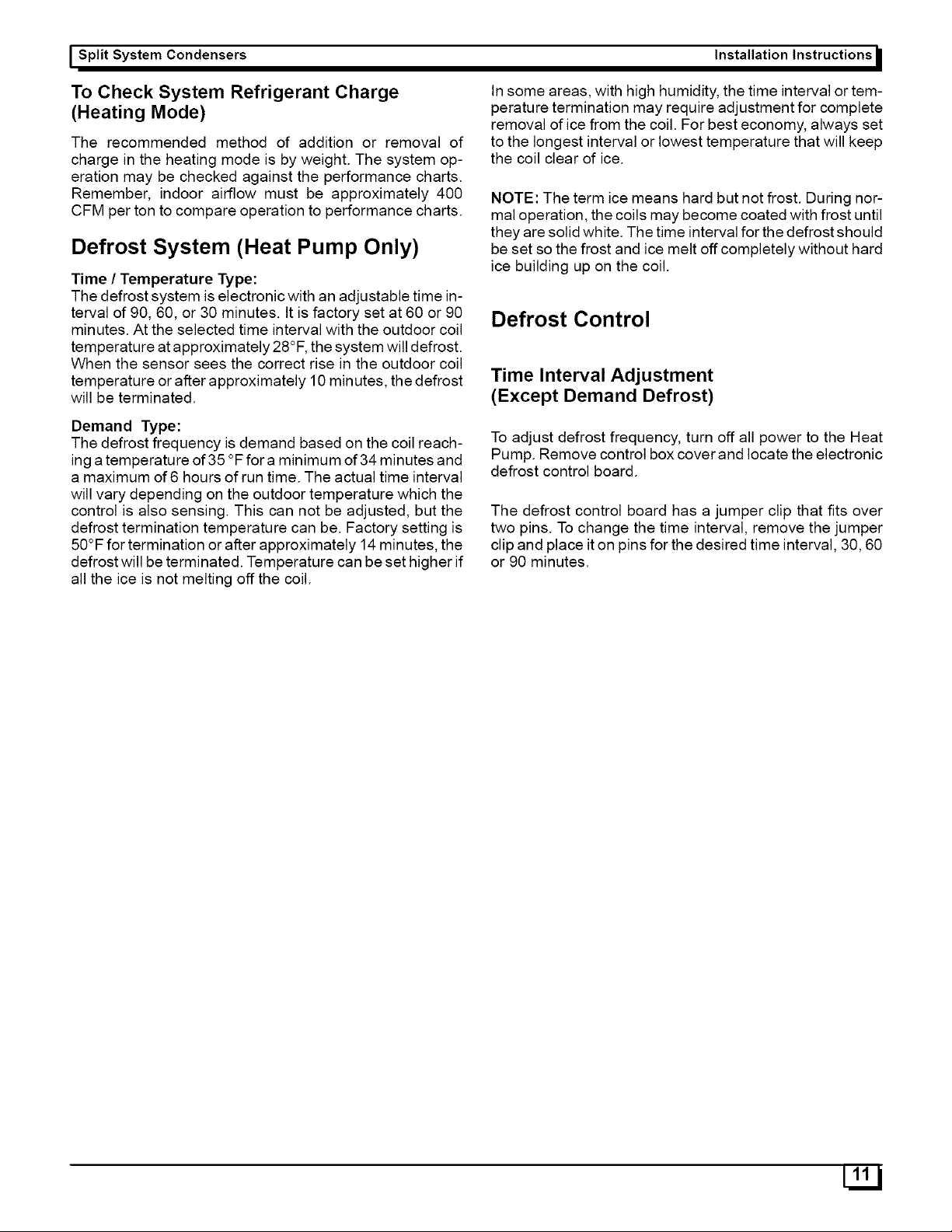
Time
Interval
Adjustment
(Except
Demand
Defrost)
To
adjust defrost
frequency,
turn
off
all
power
to
the
Heat
Pump.
Remove
control
box
cover
and
locate
the
electronic
defrost
control
board.
The
defrost
control
board
has
a
jumper
clip
that
fits
over
two
pins.
To
change
the
time
interval,
remove
the
jumper
clip
and
place
it
on
pins
for
the
desired
time
interval,
30,
60
or
90
minutes.
17
|
I
Installation
Instructions
Split
System
Condensers
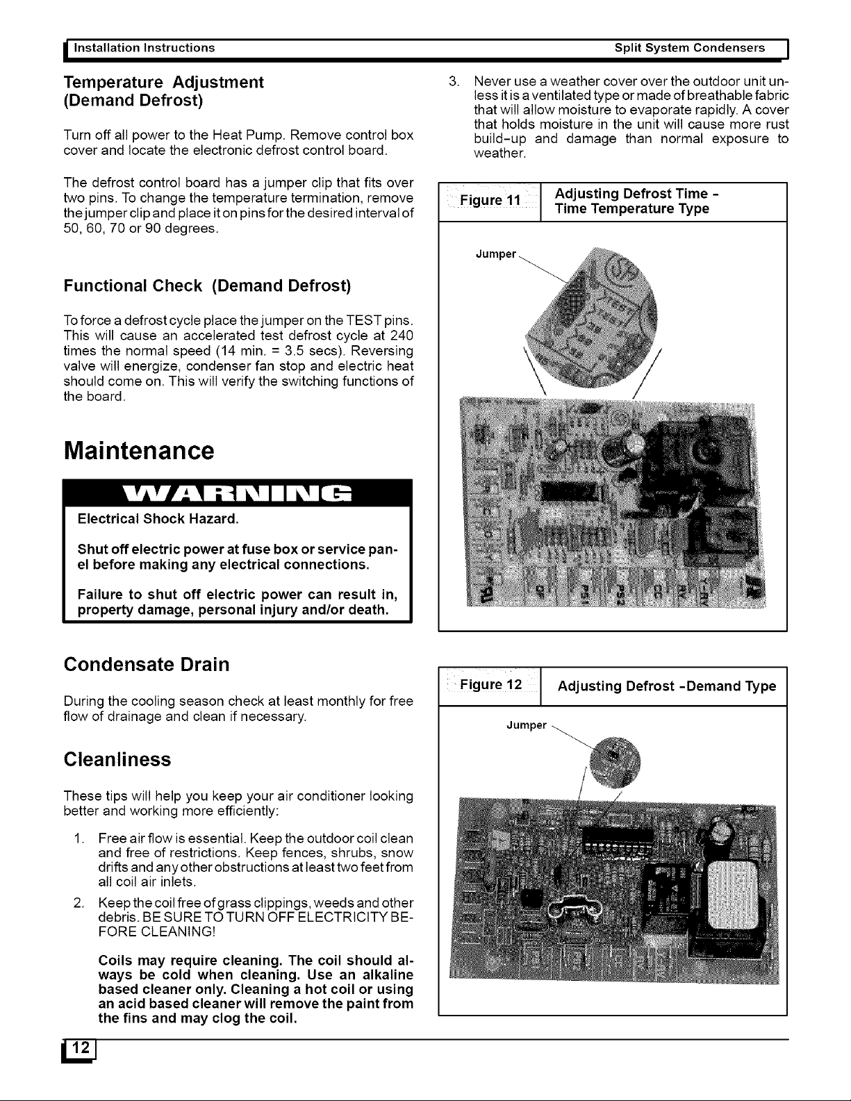
Temperature
Adjustment
(Demand
Defrost)
Turn
off
all
power
to
the
Heat
Pump.
Remove
control
box
cover
and
locate
the
electronic
defrost
control
board.
The
defrost
control
board
has
a
jumper
clip
that
fits
over
two
pins.
To
change
the
temperature
termination,
remove
the
jumper
clip
and
place
it
on
pins
for
the
desired
interval
of
50,
60,
70
or
90
degrees.
Functional
Check
(Demand
Defrost)
To
force
a
defrost
cycle
place
the
jumper
on
the
TEST
pins.
This
will
cause
an
accelerated
test
defrost
cycle
at
240
times
the
normal
speed
(14
min.
=
3.5
secs).
Reversing
valve
will
energize,
condenser
fan
stop
and
electric
heat
should
come
on.
This
will
verify
the
switching
functions
of
the
board.
Maintenance
Electrical
Shock
Hazard.
Shut
off
electric
power
at
fuse
box
or
service
pan-
el
before
making
any
electrical
connections.
Failure
to
shut
off
electric
power
can
result
in,
property
damage,
personal
injury
and/or
death.
Condensate
Drain
During
the
cooling
season
check
at
least
monthly
for
free
flow
of
drainage
and
clean
if
necessary.
Cleanliness
These
tips
will
help
you
keep
your
air
conditioner
looking
better
and
working
more
efficiently:
1.
Free
air
flow
is
essential.
Keep
the
outdoor
coil
clean
and
free
of
restrictions.
Keep
fences,
shrubs,
snow
drifts
and
any
other
obstructions
at
least
two
feet
from
all
coil
air
inlets.
2.
Keep
thecoil
free
of
grass
clippings,
weeds
and
other
debris.
BE
SURE
TO
TURN
OFF
ELECTRICITY
BE-
FORE
CLEANING!
Coils
may
require
cleaning.
The
coil
should
al-
ways
be
cold
when
cleaning.
Use
an
alkaline
based
cleaner
only.
Cleaning
a
hot
coil
or
using
an
acid
based
cleaner
will
remove
the
paint
from
the
fins
and
may
clog
the
coil.
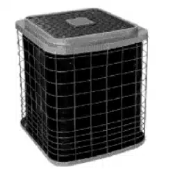
3.
Never
use
a
weather
cover
over
the
outdoor
unit
un-
less
itis
a
ventilated
type
or
made
of
breathable
fabric
that
will
allow
moisture
to
evaporate
rapidly.
A
cover
that
holds
moisture
in
the
unit
will
cause
more
rust
build-up
and
damage
than
normal
exposure
to
weather.
Adjusting
Defrost
Time
-
Figure
11
Time
Temperature
Type
Figure
12
Adjusting
Defrost
-Demand
Type
Jumper
L'2]
|
Split
System
Condensers
Installation
Instructions
J
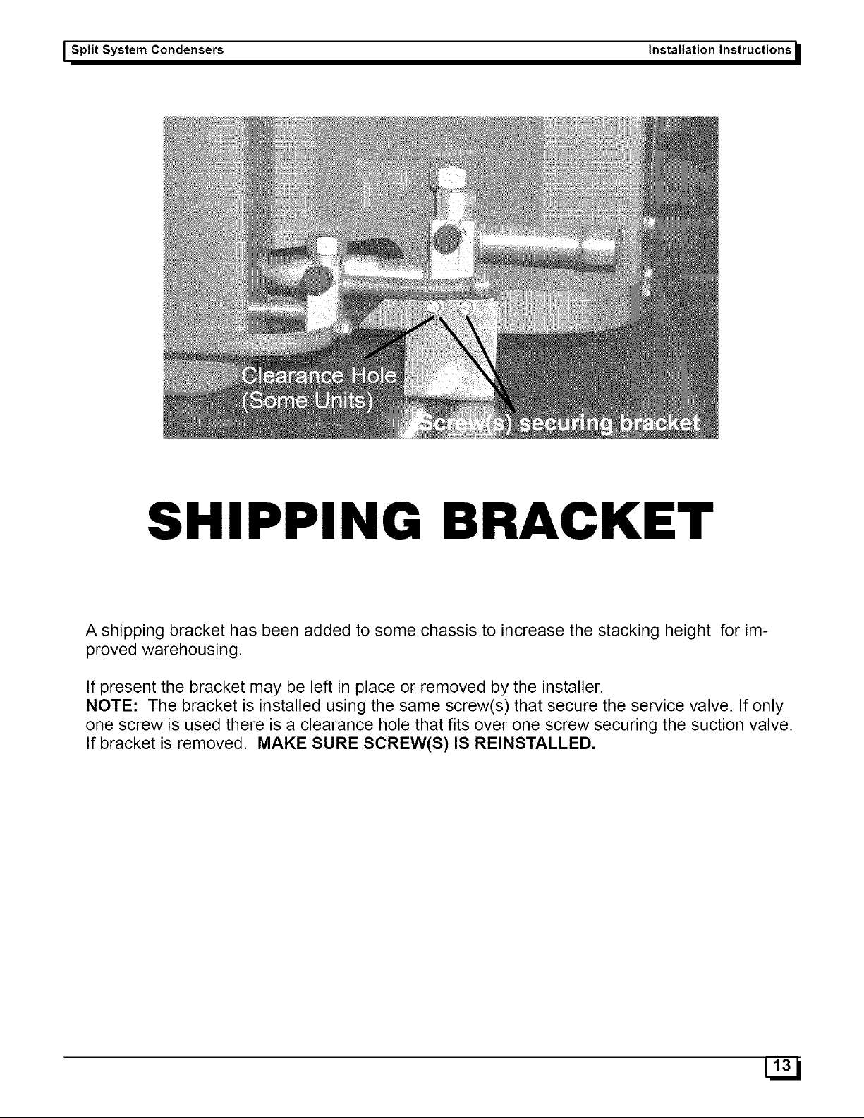
SHIPPING
BRACKET
A
shipping
bracket
has
been
added
to
some
chassis
to
increase
the
stacking
height
for
im-
proved
warehousing.
If
present
the
bracket
may
be
left
in
place
or
removed
by
the
installer.
NOTE:
The
bracket
is
installed
using
the
same
screw(s)
that
secure
the
service
valve.
If
only
one
screw
is
used
there
is
a
clearance
hole
that
fits
over
one
screw
securing
the
suction
valve.
If
bracket
is
removed.
MAKE
SURE
SCREW(S)
IS
REINSTALLED.
[13
|