
®
OPERATOR'S MANUAL
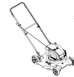
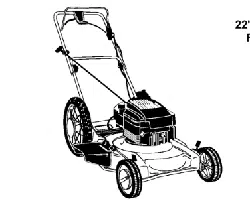
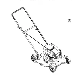
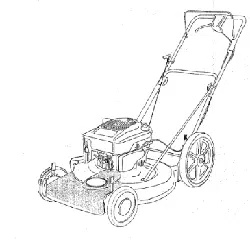
22" Side Discharge
High Wheel
Lawn Mower
Model Series 580
IMPORTANT: READ SAFETY RULES AND INSTRUCTIONS CAREFULLY
Warning: This unit is equipped with an internal combustion engine and should not be used on or near any unimproved forest-
covered, brush-covered or grass-covered land unless the engine's exhaust system is equipped witha spark arrester meeting
applicable local or state laws (if any). If a spark arrester is used, it should be maintained in effective workir_g order by the operator.
In the State of California the above is required by law (Section 4442 o_the California Public Resources Code). Other states may have
similar laws_ Federal laws apply on federal lands, A spark arrester for the muffler is available through your nearest engine authorized
service dealer or contact the service department, P.O. Box 368022 Cleveland, Ohio 44136-9722.
MTD PRODUCTS INC. P.O. BOX 368022 CLEVELAND, OHIO 44136-9722
PRINTED IN U.S.A. FORM NO. 770-10113
(10/98)
SECTION 1: FINDING LAWN MOWER MODEL NUMBER
This Operator's Manual is an important part of your new lawn mower. It will help you assemble, prepare and
maintain your mower properly. Please read and understand what it says.
Before you start to prepare your equipment for its first usel please locate the model plate and copy the
information from it in the space provided below. The information on the model plate is very important if you
need help from your dealer or the MTD customer support department.
• Every lawn mower has a model plate. You can locate it by standing behind the unit in the operating
position and looking down at the rear of the deck.
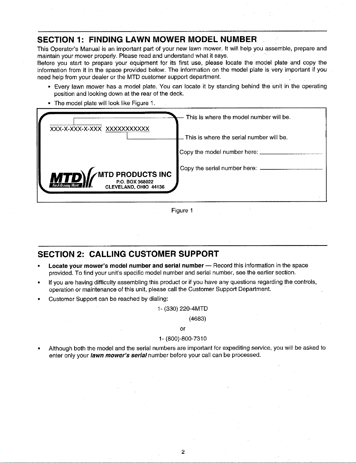
• The model plate will look like Figure 1.
re the model number will be.
XXX-X-XXX-X-XXX XXXXXXXXXXX
L_rwill be.
the model number here:
MTD f/ copythe serial number here:
MTD PRODUCTS INC
lira P.O BOX 368022
__J_L CLEVELAND, OHIO 44136
Figure 1
SECTION 2: CALLING CUSTOMER SUPPORT
• Locate your mower's model number and serial number -- Record this information in the space
provided To find your unit's specific model number and serial number see the earlier section
•If you are having difficulty assembling this product or if you have any questions regarding the controls
operation or maintenance ofthis unit please call the Customer Support Department
•Customer Support can be reached by dialing:
1- (330) 220-4MTD
(4683)
or
1- (800)-800-7310
• Although both the model and the serial numbers are important for expediting service, you will be asked to
enter only your lawn mower's serial number before your call can be processed.
SECTION 3: IMPORTANT SAFE OPERATION PRACTICES
&
A
A
WARNING: This symbol points out important safety instructions which, if not followed, could
endanger the personal safety and/or property of yourself and others. Read and follow all instructions
in this manual before attempting to operate your lawn mower. Failure to comply with these
instruct{ass may result in personal injury. When you see this symbol, heed itswarning.
WARNING: The Engine Exhaust from this product contains chemicals known to the State of
California to cause cancer. 0irth defects or other reproductive harm.
WARNING: Your lawn mower was built to be operated according to the rules for safe operation in
this manual, As with any type of power equtprnent, carelessness or error on the part of the operator
can result in serious injury. This lawn mower is capable of amputating hands and feet and throwing
objects. Failure to observe the following safety instructions could result in serious injury or death.
1. General Operation
•Read this operator's manual carefully in its entirety
before attempting to assemble this machine. Read.
understand, ane follow all instructions on the
machine and in the manual(s) before operation. Be
completely familiar with the controls and the Draper
use of tills machine before operating it Keep this
manual in a safe place for future reference and for
ordering replacement pans.
•Your rotary mower s a precision olece of power
equipment, not a plaything. Therefore exercise
extreme caution at all times. Your unit has been
designed to perform one job: to mow grass. Do not
use it for any omer purpose.
•Never allow children under 1,$ years old _o operate
a power mower. Children 14 years old and over
should only operate mower under close parental
supervision. Only responsible ndividuals who are
familiar with these rules of safe oseration should be
allowed to use your mower.
• Keep the area of operation clear of all _ersons,
particularly small children and pets. Stop engine
when they are in the vicinity of your mower to help
prevent blade contact or thrown object n]ury.
Although the area of operation should be
completely cleared of foreign objects, an object
may have been overlooked and could be
accidentally thrown ey the mower m any direction
and cause serious personal injury to the operator or
any others allowed in the area.
• Wear sturdy, rough-soled WOrK shoes and close-
fitting slacks and shirts. Shirts and pants that cover
the arms ant legs an_ steel-toed shoes are
recommended. Do not wear Ioose fitting clothes or
iewelry. They can be caugnt in moving parts. Never
operate a unit in bare feet. sandals, slippery or light
weight (e.g. canvas) shoes.
• Always wear safety glasses or safety goggles
during operation or while performing an adjustment
or repair, to protect eyes from foreign objects that
may be thrown from the machine in any direction.
• Thoroughly inspect the area where the equJpment
is to be used. Remove all stones, sticks, wire,
9ones, toys and other foreign objects which could
_e picked UD and thrown by the mower in any
direction and cause seoous personal injury to the
operator or any others allowed in the area. Plan
your mowing pattern to avoid discharge of material
toward roads, sidewalks bystanders and the like.
To help avoid a thrown objects injury, Keep
children, bystanders and helpers at least 75 feet
from the mower while it is in operation.
• Do no_ put hands or feet near or under rotating
parts. Keep clear of discharge open=ng at alI times
as the rotating blade can cause injury.
• Many injuries occur as a result of the mower being
pulled over the foot during a fall. Do not sang on to
the mower if you are falling; release the handle
immediateJy.
•Never pull the mower toward you while you are
walking. If you must back the mower away from a
wall or obstruction first look down and behind, and
then follow these steps:
1 Step back from the mower to fully extend your
arms.
2 Be sure you are well balancec with sure
footing,
3 Pull the mower back slowly, no more than half
way toward you.
4 Repeat these steps as needed.
• Do not ooerate the mower while under the
influence of alcoho or drugs.
• Do 3st engage the self-propelled mechanism on
units so equipped while starting engine.
• The blade control handle is a safety device. Never
attempt to bypass its operation, Doing so makes
the safety device inoperative and may result in
personal injury through contact with the rotating
bIade. The blade control handle must operate
easily in both directions and automatically return to
the disengaged position when released.
• Never operate the mower enwet grass. Always be
sure of your footing. A slip and fall can cause
3
serious personal injury. Keep a firm hold on the
handle and walk, never run. If you feel you are
losing your footing, RELEASE THE BLADE
CONTROL HANDLE IMMEDIATELY and the blade
will stop rotating within three seconds.
•Mow only in daylight or good artificial light.
• Stop the blade when crossing gravel drives, walks
or roads.
•If the equipment should start to vibrate abnormally.
stop the engine and check immediately for the
cause. Vibration is generally a warning of trouble.
• Shut the engine off and wait until the blade comes
to a complete stop before removing the grass
catcher or unclogging the chute. The cutting blade
continues to rotate for a few seconds after the
engine is shut off. Never place any part of the body
in the blade area until you are sure the blade has
stopped rotating.
• Never operate mower without proper guards, grass
catcher, plates or other safety protective devices in
place.
• Muffler and engine become hot and can cause a
burn. Do not touch.
• Only use accessories approved for this machine by
the manufacturer. Read, understand, and follow all
instructions provided with the approved accessory.
• If situations occur which are not covered in this
manual, use care and good judgment. Contact your
dealer for assistance. Telephone 1-800-800-7310
for the name of your nearest dealer.
• Do not adjust the throttle control while the engine is
still running.
2. Slope Operation
For your safety, use the slope gauge included as part of
this manual to measure slopes before operating this unit
on a sloped or hilly area. If the slope is greater than 15
degrees as shown on the slope gauge, do not operate this
unit on that area or serious injury could result,
Do:
• Mow across the face of slopes; never up and down.
Exercise extreme caution when changing direction
on slopes.
• Watch for holes, ruts, hidden objects, or bumps.
Tall grass can hide obstacles.
• Always be sure of you_ footing. A slip and fall can
cause serious personal injury. If you feel you are
losing your balahce release the blade control
handle immediately and the blade will stop in less
than 3 seconds.
Do not:
• Do not mow near drop-offs, ditches or
embankments. The operator could lose footing or
balance.
• Do not mow slopes greater than 15 degrees as
shown on the slope gauge.
• Do not mow on wet grass. Reduced footing could
cause slipping.
3. Children
Tragic accidents can occur if the operator is not alert to the
presence of children. Children are often attracted to the
mower and the mowing activity. Never assume that
children will remain where you last saw them.
Keep children out of the mowing area and under
the watchful care of a responsible adult other than
the operator.
Be alert and turn mower off if a child enters the
area.
Before and while moving backwards, look behind
and down for small children or other objects.
Never allow children under age 14 to operate the
mower. Children 14 years of age and above
should read and understand the operation
instructions and safety rules in this manual,
Use extreme care when approaching blind corners,
shrubs, trees, or other objects that may obscure
your vision of a child or hazard.
4. Service
Use extreme care in handling gasoline and other
fuels. They are extremely flammable and the
vapors are explosive.
Use only an approved gasoline container.
Never remove gas cap or.add fuel while the engine
is running. Allow engine to cool at least two
minutes before refueling.
Replace gasoline cap securely and wipe off any
spilled gasoline before starting the engine as it may
cause a fire or explosion.
Extinguish all cigarettes, cigars, pipes and other
sources of ignition.
Never refuel machine indoors because flammable
vapors will accumulate in the area.
Never store the machine or fuel container inside
where there is an open flame or spark such as a
gas water heater, space heater, or furnace.
Never run an engine inside a closed area.
To reduce fire hazard, keep mower free of grass,
leaves, or other debris build-up. Clean up oil or fuel
spillage. Allow mower to cool at least 5 minutes
before storing.
Before cleaning, repairing, or inspecting, make
certain the blade and all moving parts have
4
stopped.Disconnectthesparkplugwire,andkeep
mewireawayfromthespark#lugto prevent
accidentalstarting.
•Check the blade and engine mounting bolts a_
freauent intervals for proper tightness. Also.
visually inspect blade for damage (e.g., bent.
cracked or worn). Replace with blade which meets
original equipment specifications listed n this
manual.
Grass catcher components are subject to wear.
damage and deterioration, which could expose
moving parts or allow objects to be thrown. For
safety protection, frequently check components and
replace with manufacturer's recommended parts.
when necessary.
Mower blades are sharp and can cut. Wrap the
blade(s) or wear gloves, and use extra caution
when servicing them.
- Keel: all nuts. bolts, and screws tight to be sure the •
equipment is in safe working condition.
• Never tamper with safety devices Check their
proper operation regularly.
•After striking a foreign object, stop the engine,
remove the wire from the spark plug, and
moroughly _nspect the mower for any damage,
Repair the damage before starting and operating
the mower.
. Never attempt to make a wheel or cutting height
adjustment while the engine is running.
Do not change the engine governor setting or
overspeed the engine. Excessive engine speeds
are dangerous.
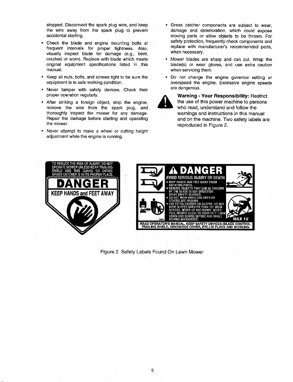
Warning - Your Responsibility: Restrict
the use of this power machine to persons
who read. understand and follow the
warnings and instructions in this manual
and on the machine, Two safety labels are
reoroduced in Figure 2.
DANGER
Figure 2 Safety Labels Found On Lawn Mower
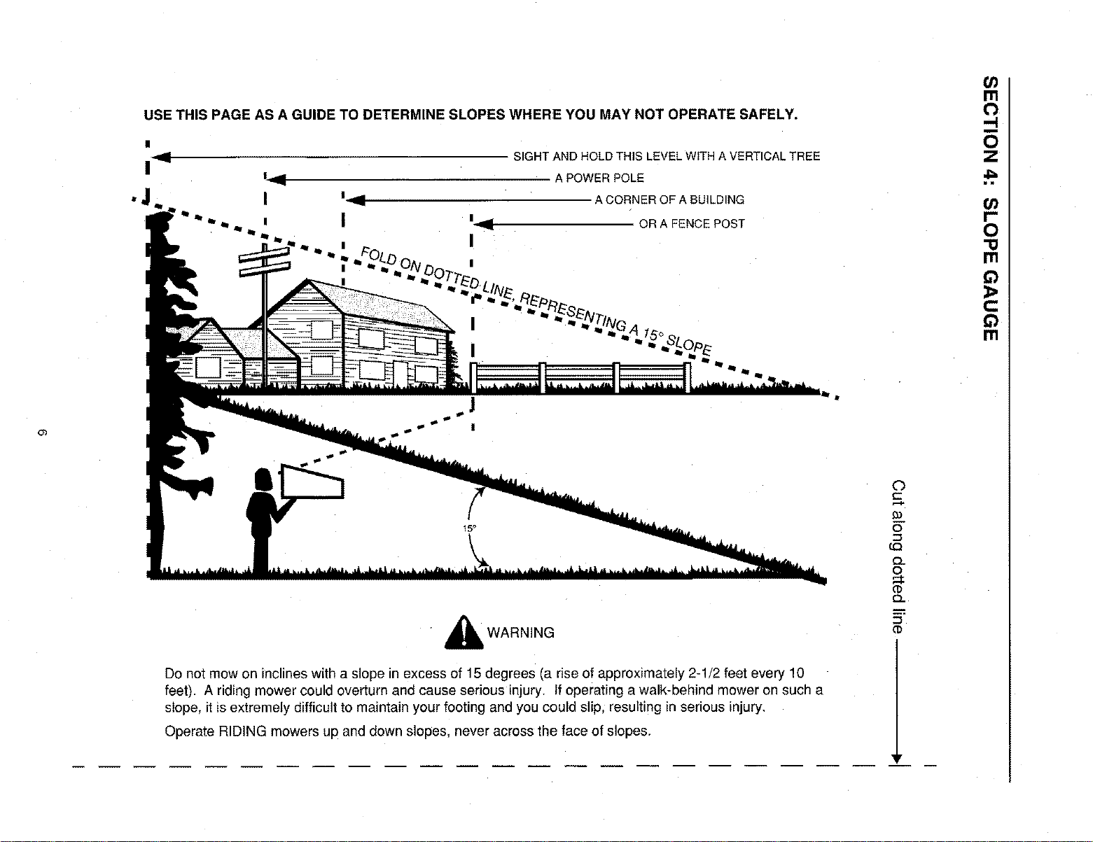
USE THIS PAGE AS A GUIDE TO DETERMINE SLOPES WHERE YOU MAY NOT OPERATE SAFELY.
'.., zO
| _ SIGHT AND HOLD THIS LEVEL WITH A VERTICAL TREE
!_ A POWERPOLE
G)
d_ WARNING
Do not mow on inclines with a slope in excess of 15 degrees (a rise of approximately 2-1/2 feet every 10
feet). A riding mower could overturn and cause serious injury. If operating a walk-behind mower on such a
slope, it is extremely difficult to maintain your footing and you could slip, resulting in serious injury.
Operate RIDING mowers up and down slopes, never across the face of slopes.
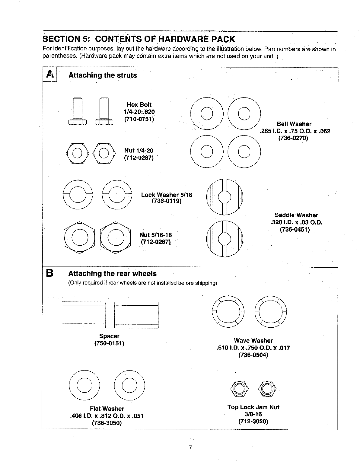
SECTION 5: CONTENTS OF HARDWARE PACK
For identification purposes, lay out the hardware according to the illustration below. Part numbers are shown in
parentheses CHardware pack may contain extra items which are not used on your unit. )
A_ Attaching the struts
Hex Bolt
1/4-20:.620
(710-0751 )
Nut 1/4-20
(712-0287)
EB
Lock Washer 5116
(736-0119)
Nut 5/16-18
(712-0267)
Saddle Washer
.320 I.D. x .83 O.D.
(736-0451)
Attaching the rear wheels
(Onlyrequiredifrearwheelsare notinstalledbeforeshipping)
Spacer
(750-0151 ) Wave Washer
.510 I.D. x .750 O,D. x .017
(736-0504)
Flat Washer
.406 I.D. x .812 O.D, x .051
(736-3050)
©©
Top Lock Jam Nut
3/8-16
(712-3020)
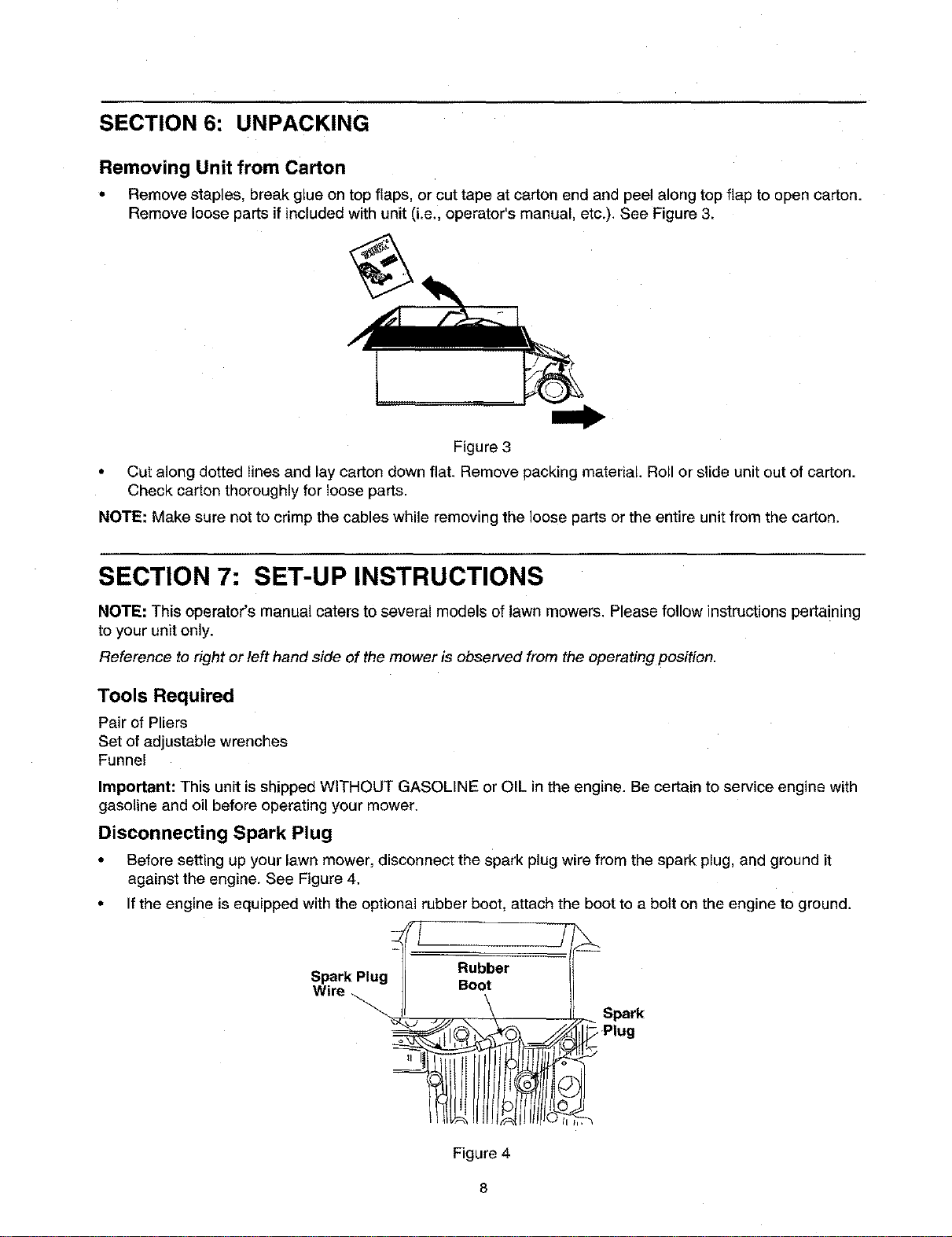
SECTION 6: UNPACKING
Removing Unit from Carton
• Remove staples, break glue on top flaps, or cut tape at carton end and _eel along top flap to open carton.
Remove loose parts if included with unit (i.e., operators manual, etc.). See Figure 3.
Figure 3
•Cut along dotted lines and lay carton down flat. Remove packing material. Roll or slide unit out of carton.
Check carton thoroughly for loose parts.
NOTE: Make sure not to crimp the cables while removing the loose parts or the entire unit from the carton.
SECTION 7: SET-UP INSTRUCTIONS
NOTE: This operator's manual caters to several models of lawn mowers. Please follow instructions pertaining
to your unit only.
Reference to right or left hand side of the mower is observed from the operating position.
Tools Required
Pair of Pliers
Set of adjustable wrenches
Funnel
Important: This unit is shipped WITHOUT GASOLINE or OIL in the engine. Be certain to service engine with
gasoline and oil before operating your mower.
Disconnecting Spark Plug
• Before setting up your lawn mower, disconnect the spark plug wire from the spark plug, and ground it
against the engine. See Figure 4.
• If the engine is equipped with the optional rubber boot, attach the boot to a bolt on the engine to ground.
._2
Spark Plug _= ub.ber _
Wire \11 uoo, /
II \ J_.. Spark
Figure 4
8
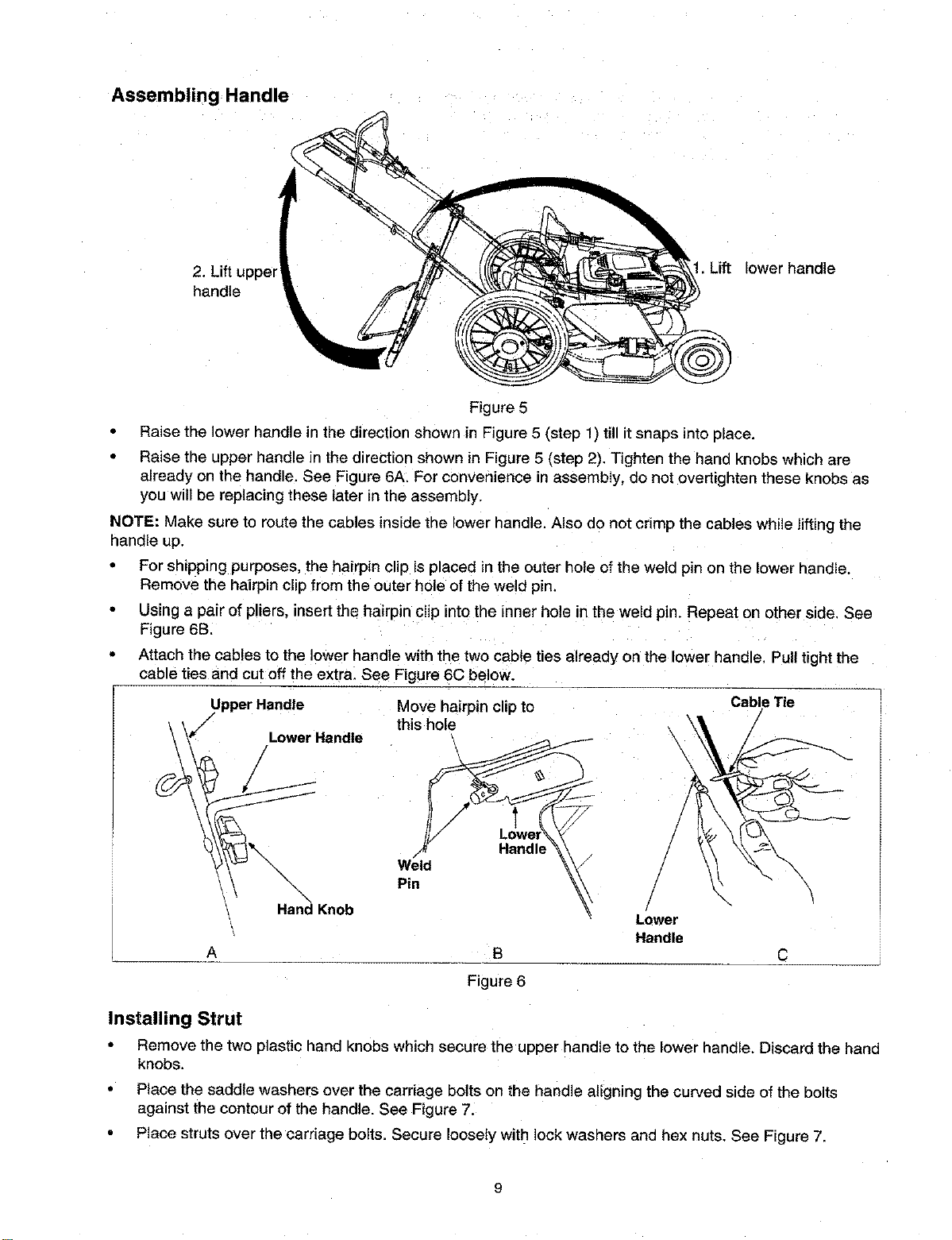
Assembling Handle
2. Lift uppel
handle
Lift lower handle
Figure 5
Raise the lower handle in the direction shown in Figure 5 (step 1) till it snaps into place.
Raise the upper handle in the direction shown in Figure 5 (step 2). Tighten the hand knobs which are
already on the handle. See Figure 6A, For convenience in assembly, do not overtighten these knobs as
you will be replacing these later in the assembly,
NOTE: Make sure to route the cables inside the lower handle. Also do not crimp the cables while lifting the
handle up.
•For shipping purposes, the hairpin clip is placed in the outer hole of the weld pin on the lower handle.
Remove the hairpin clip from the outer hole of the weld pin.
Using a pair of pliers, insert the hairpin clip into the inner hole it. the weld pin. Repeat on other side. See
=igure 6B,
Attach the cables to the lower handle with the two cable ties already on the lower handle. Pull tight the
cable ties and cut off the extra. See Figure 6C below.
Upper Handle Move hairpin clipto
this hole '_i
Lower Handle \
". /
Hand Knob _Lower
Handle
A
Cable Tie
/
Figure 6
Installing Strut
Remove the two plastic hand knobs which secure the upper handle to the Rowerhandle. Discard the hand
knobs.
Place the saddle washers over the carriage bolts on the handle aligning the curved side of the bolts
against the contour of the handle. See Figure 7.
•Place struts over tl_e carnage bolts. Secure loosely with lock washers and hex nuts. See Figure 7.
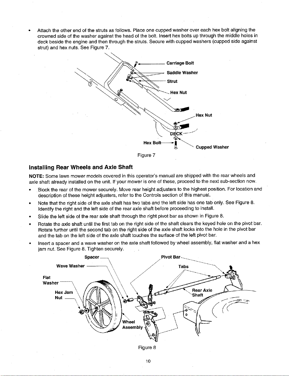
Attachtheotherendofthestrutsasfollows.Placeonecuppedwasherovereachhexboltaligningthe
crownedsideofthewasheragainsttheheadofthebolt.Inserthexboltsupthroughthemiddleholesin
deckbesidetheengineandthenthroughthestruts,Securewithcuppedwashers(cuppedsideagainst
strut)andhexnuts.SeeFigure7.
\
Carriage Bolt
Saddle Washer
Cupped Washer
Installing Rear Wheels and Axle Shaft
NOTE: Some lawn mower models covered in this operator's manual are shipped with the rear wheels and
axle shaft already installed on the unit. Ifyour mower is one of these, proceed to the next sub-section now.
-Block the rear of the mower securely. Move rear height adjusters to the highest position. For location and
description of these height adjusters, refer to the Controls section of this manual.
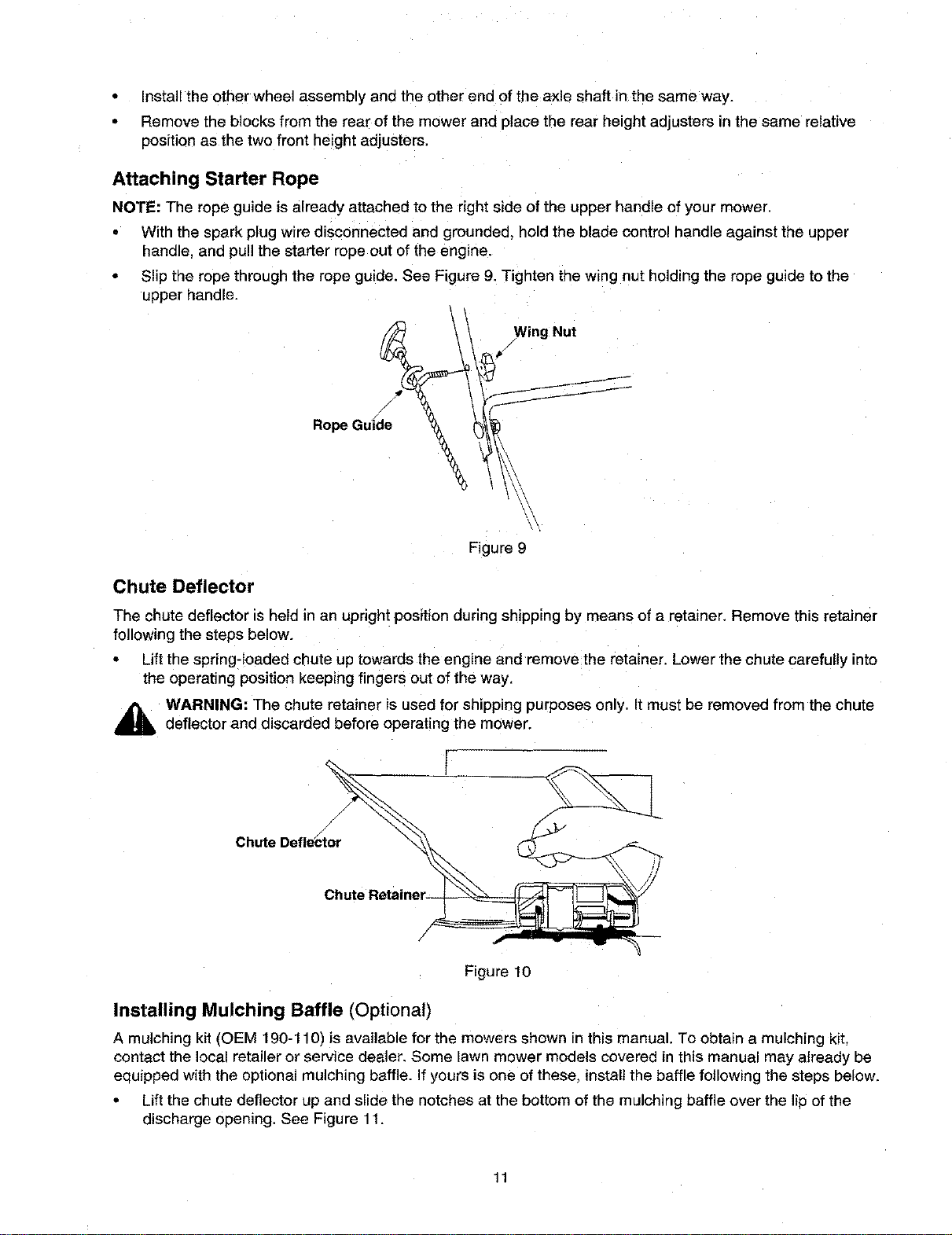
•Note that the right side of the axle shaft has two tabs and the left side has one tab only. See Figure 8.
Identify the right and the left side of the rear axle shaft before proceeding to install.
•Slide the left side of the rear axle shaft through the right pivot bar as shown in Figure 8.
•Rotate the axle shaft until the first tab on the right side of the shaft clears the keyed hole on the pivot bar.
Rotate further until the second tab on the right side of the axle shaft locks into the hole in the pivot bar
and the tab on the left side of the axle shaft touches the surface of the left pivot bar.
Insert a spacer and a wave washer on the axle shaft followed by wheel assembly, flat washer and a hex
jam nut. See Figure 8. Tighten securely.
Spacer
Wave Washer \\\
Flat \
Washer _-_ J
He)(Jam
Nut --, \\
Wheel
Assembly
Figure 8
10
• Install the other wheel assembly and the other end of the axle shaft in the same way.
•Remove the blocks from the rear of the mower ana place the rear height adjusters in the same relative
position as the two front height adjusters.
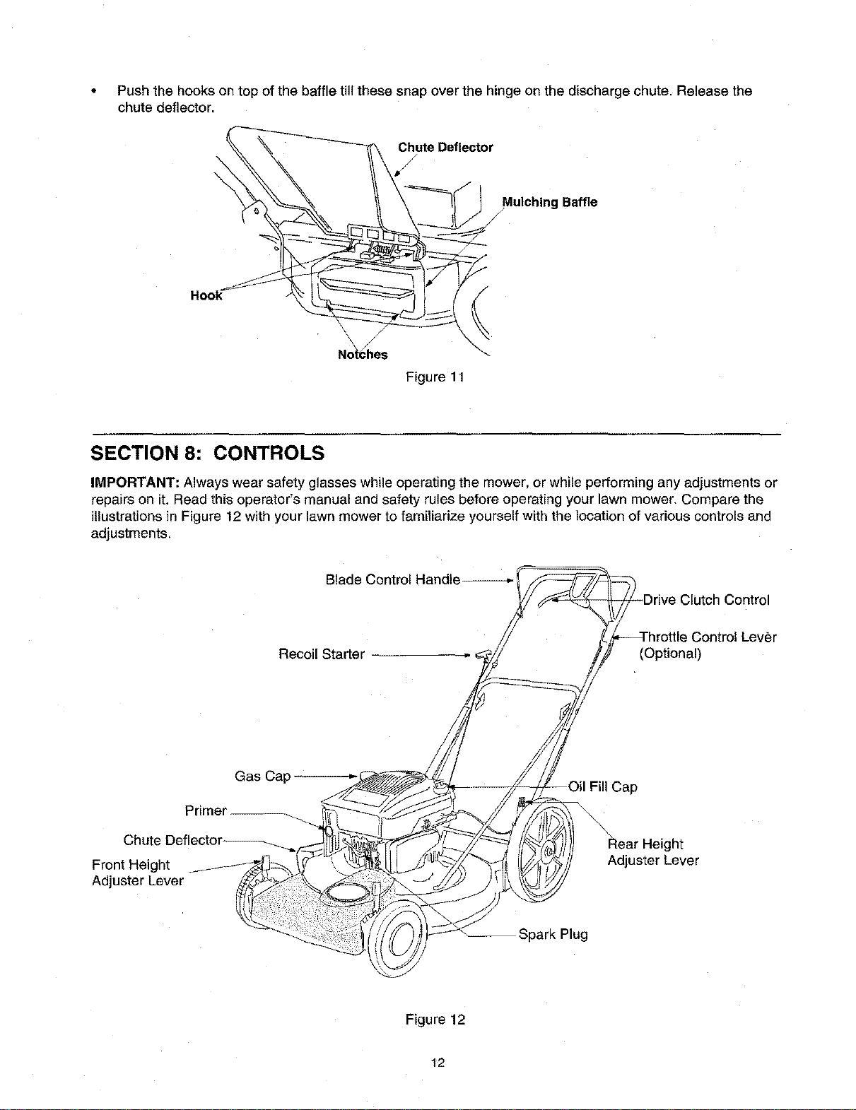
Attaching Starter Rope
NOTE: The rope guide is already attached to the right side of the upper handle of your mower.
• With the spark plug wire disconnected and grounded, hold the blade control handle against the upper
handle, and pull the starter rope out of the engine.
Slip the rope through the rope guide. See Figure 9. Tighten the wing nut holding the rope guide to the
upper handle.
Rope Gui/de__
Wing Nut
Figure 9
Chute Deflector
The chute deflector is held m an upright position during shipping by means of a retainer. Remove this retainer
following the steps below.
Lift the spring-loaded chute up towards the engine and remove the retainer. Lower the chute carefully into
the operating position keeping fingers out of the way.
,_ WARNING: The chute retainer is used for shipping purposes only. It must be removed from the chute
deflector and discarded before operating the mower.
Chute Deflector
/
Figure 10
Installing Mulching Baffle (Optional)
A mulching kit ('OEM 190-110) is available for the mowers shown in this manual. To obtain a mulching kit,
contact the local retailer or service dealer. Some lawn mower models covered in this manual may already be
eauipped with the optional mulching baffle. If yours is one of these, install the baffle following the steps below.
Lift the chute deflector up and slide the notches at the bottom of the mulching baffle over the lid of the
discharge opening. See Figure 11.
11
• Pushthehooksontopofthebaffletillthesesnapoverthehingeonthedischargechute.Releasethe
chutedeflector.
\
\
Chute Deflector
/
Mulching Baffle
Hook
Figure 11
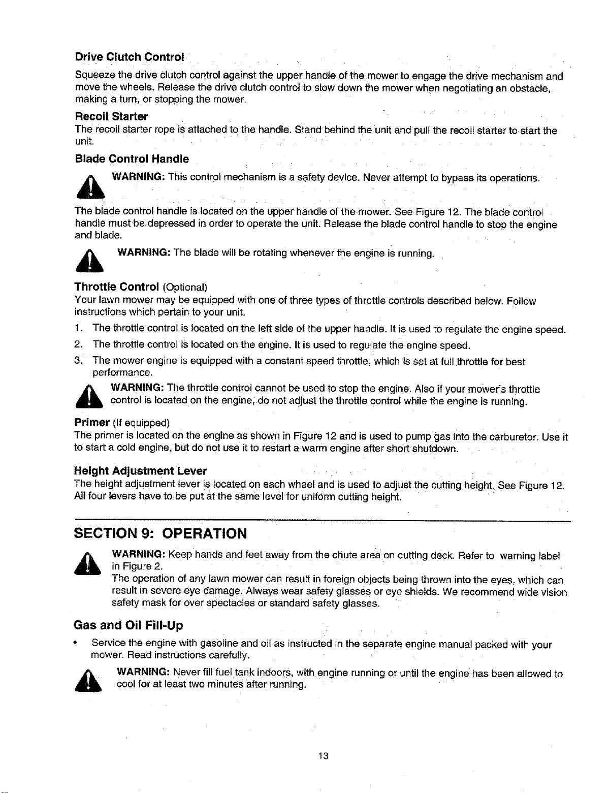
SECTION 8: CONTROLS
IMPORTANT: Always wear safety glasses while operating the mower, or while performing any adjustments or
repairs on it. Read this operator's manual and safety rules before operating your lawn mower. Compare the
illustrations in Figure 12 with your lawn mower to familiarize yourself with the location of various controls and
adjustments,
Blade Control Handle Clutch Control
Recoil Starter e Control Lever
(Optional)
Primer
Chute
Front Height
Adjuster Lever
Gas Cap Cap
ght
Adjuster Lever
Spark Plug
Figure 12
12
Drive Clutch Control
Squeeze the drive clutch control against the upper handle of the mower to engage the drive mechanism and
move the wheels. Release the drive clutch control to slow down the mower when negotiating an obstacle,
making a turn, or stopping the mower.
Recoil Starter
The recoil starter rope is attached to the handle. Stand behind the unit and pull the recoil starter to start the
unit.
Blade Control Handle
,i_ WARNING: This control mechanism is a safety device. Never attempt to bypass its operations.
The blade control handle is located on the upper handle of the mower. See Figure 12. The blade control
handle must be depressed in order to operate the unit. Release the blade control handle to stop the engine
and blade.
WARNING: The blade will be rotating whenever the engine is running.
Throttle Control (Optional)
Your lawn mower may be equipped with one of three types of throttle controls described below, Follow
instructions which pertain to your unit.
1. The throttle control is located on the left side of the upper handle, It is used to regulate the engine speed,
2. The throttle control is located on the engine. It is used to regulate the engine speed.
3. The mower engine is equipped with a constant speed throttle, which is set at full throttle for best
performance.
WARNING: The throttle control cannot be used to stop the engine, Also if your mower's throttle
control is located on the engine, do not adjust the throttle control while the engine is running.
Primer (If equipped)
The primer is located on the engine as shown in Figure 12 and is used to pump gas into the carburetor: Use it
to start a cold engine, but do not use it to restart awarm engine after short shutdown.
Height Adjustment Lever
The height adjustment lever is ocated on each wheel and is used t° adjust the cutting height. See Figure 12.
All four levers have to be put at the same level for uniform cutting height.
SECTION 9: OPERATION
WARNING: Keep hands and feet away from the chute area on cutting deck. Refer to warning label
in Figure 2,
The operation of any lawn mower can result in foreign objects being thrown into the eyes, which can
result in severe eye damage, Always wear safety glasses or eye shields. We recommend wide vision
safety mask for over spectacles or standard safety glasses:
Gas and Oil Fill-Up
•Service the engine with gasoline and oilas instructed in the separate engine manual packed with your
mower. Read instructions carefully.
WARNING: Never fill fuel tank indoors, with engine running or until the engine has been allowed to
cool for at least two minutes after running,
13
Before Starting
•Attach spark plug wire to spark plug. If your unit is equipped with a rubber boot over the end of the spark
plug wire, make certain the metal cap on the end ef the spark plug wire (inside the rubber boot) is
fastened securely over the metal tip on the spark plug.
To Start Engine and Engage Blade
• If engine is equipped with a throttle control lever, move the lever all the way forward to the FAST (rabbit)
position, Your mower is designed to operate at full throttle. Engines with fixed throttles operate _,tfull throttle
too.
• If engine is equipped with a pdmer, prime engine as instructed in the separate engine manual packed
with your unit.
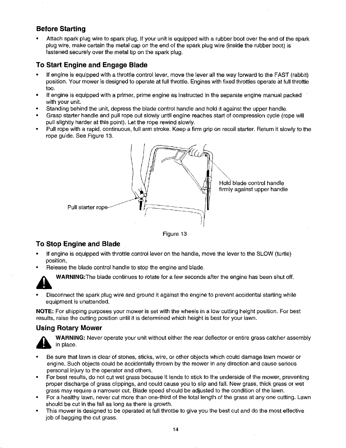
• Standing behind the unit, depress the blade control handle and hold it against the upper handle.
• Grasp starter handle and pull rope out slowly until engine reaches start of compression cycle (rope will
pull slightly harder at this point). Let the rope rewind slowly.
• Pull rope with a rapid, continuous, full arm stroke. Keep a firm grip on recoil starter. Return it slowly to the
rope guide. See Figure 13.
handle
firmly against upper handle
Figure 13
To Stop Engine and Blade
• If engine is equipped with throttle control lever on the handle, move the lever to the SLOW (turtle)
position.
• Release the blade control handle to stop the engine and blade.
lb WARNING:The blade continues to rotate for a few seconds after the engine has been shut off.
• Disconnect the spark plug wire and ground it against the engine to prevent accidental starting while
equipment is unattended.
NOTE: For shipping purposes your mower is set with the wheels in a low cutting height position. For best
results, raise the cutting position until it is determined which height is best for your lawn.
Using Rotary Mower
WARNING: Never operate your unit without either the rear deflector or entire grass catcher assembly
in place.
• Be sure that lawn is clear of stones, sticks, wire, or other objects which could damage lawn mower or
engine. Such objects could be accidentally thrown by the mower in any direction and cause serious
personal injury to the operator and others.
• For best results, do not cut wet grass because it tends to stick to the underside of the mower, preventing
proper discharge of grass clippings, and could cause you to slip and fall. New grass, thick grass or wet
grass may require a narrower cut. Blade speed should be adjusted to the condition of the lawn.
• For a healthy lawn, never cut more than one-third of the total length of the grass at any one cutting. Lawn
should be cut in the fall as long as there is growth.
• This mower is designed to be operated at full throttle to give you the best cut and de the most effective
job of bagging the cut grass.
14
•Squeeze the drive clutch control against the upper handle of the mower to engage the drive mechanism
and move the wheels. Release the drive clutch control to slow down the mower when negotiating an
obstacle, making a turn. or stopping the mower.
AWARNING: If you strike a foreign object, stop the engine. Remove wire from spark plug, thoroughly
respect the mower for any damage, and repair the damage before restarting and operating the
mower. Extensive vibration of the mower during operation is an indication of damage. The unit
should be promptly inspected and repaired.
Using Mulcher (Optional Equipment)
For effective mulching, do not cut wet grass because ittends to stick to the underside of the deck.
oreventing proper mulching of grass clippings.
New or thick grass may require a narrower cut. The ground speed of the mower should be adjusted to the
condition of the tawn. If mowing has been delayed and the grass has been allowed to grow in excess of
4", mulching is not recommended. Mow using the grass bag (if so equipped) to reduce the grass height to
3-1/4" maximum before mulching.
SECTION 10: ADJUSTMENTS
,i_ WARNING: Always stop the engine and disconnect the spark plug wire before performing any
adjustments on your lawn mower.
Adjusting Cutting Height
IMPORTANT: All wheels must be placed in the same relative position. For rough or uneven lawns move the
height adjustment lever to a higher position. This will help stop scalping of the grass.
There isan adjusting plate and thumb lever at each wheel to enable the operator to adjust the mower's
cutting height. Each adjusting plate has nine height positions. Height of cut will be changed when you move
the thumb lever from one hole to another within these nine positions.
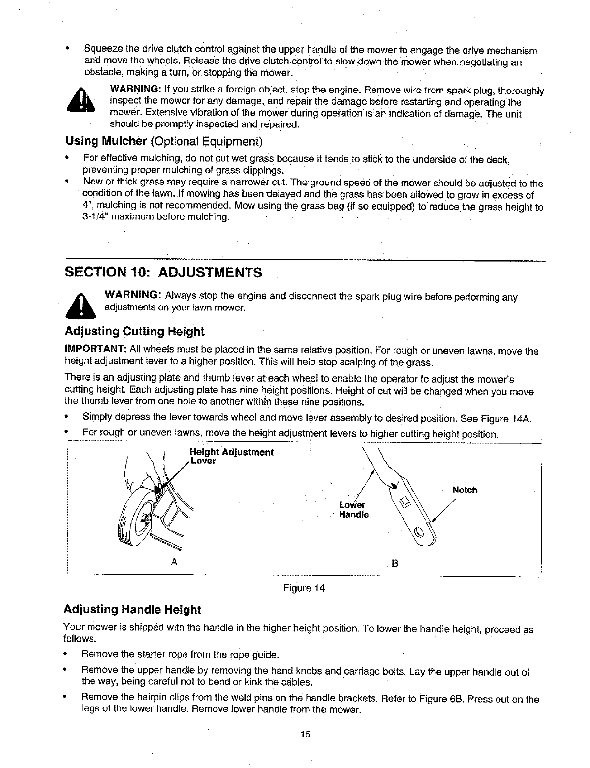
•Simply depress the lever towards wheel and move lever assembly to desired position. See Figure 14A.
• For rough or uneven lawns, move the height adjustment levers to higher cutting height position.
Height Adjustment
Lever
A
Notch
Lower /
Handle /
B
Figure 14
Adjusting Handle Height
Your mower is shipped with the handle in the higher height position. To lower the handle height, proceed as
follows.
Remove the starter rope from the rope guide.
Remove the upper handle by removing the hand knobs and carriage bolts. Lay the upper handle out of
the way, being careful not to bend or kink the cables.
•Remove the hairpin clips from the weld pins on the handle brackets. Refer to Figure 6B. Press out on the
legs of the lower handle. Remove lower handle from the mower.
15
Turn the lower handle around so the notch on the bottom of the lower handle is facing forward as shown
in Figure 14B. Reassemble, placing the bottom holes in the handle over the weld pins in the handle
mounting bracket.
Reassemble the upper handle to the lower handle.
Place the hairpin clips in the inner holes of the weld pins and attach the starter rope as instructed in the
Assembly section.
Adjusting Throttle Control
If your lawn mower is equipped with an adjustable throttle control on the handle (refer to the first category of
throttle control described on page 13 of this manual), adjust it following instructions below.
Adjust the throttle control only if it is out of adjustment, or if it has been replaced.
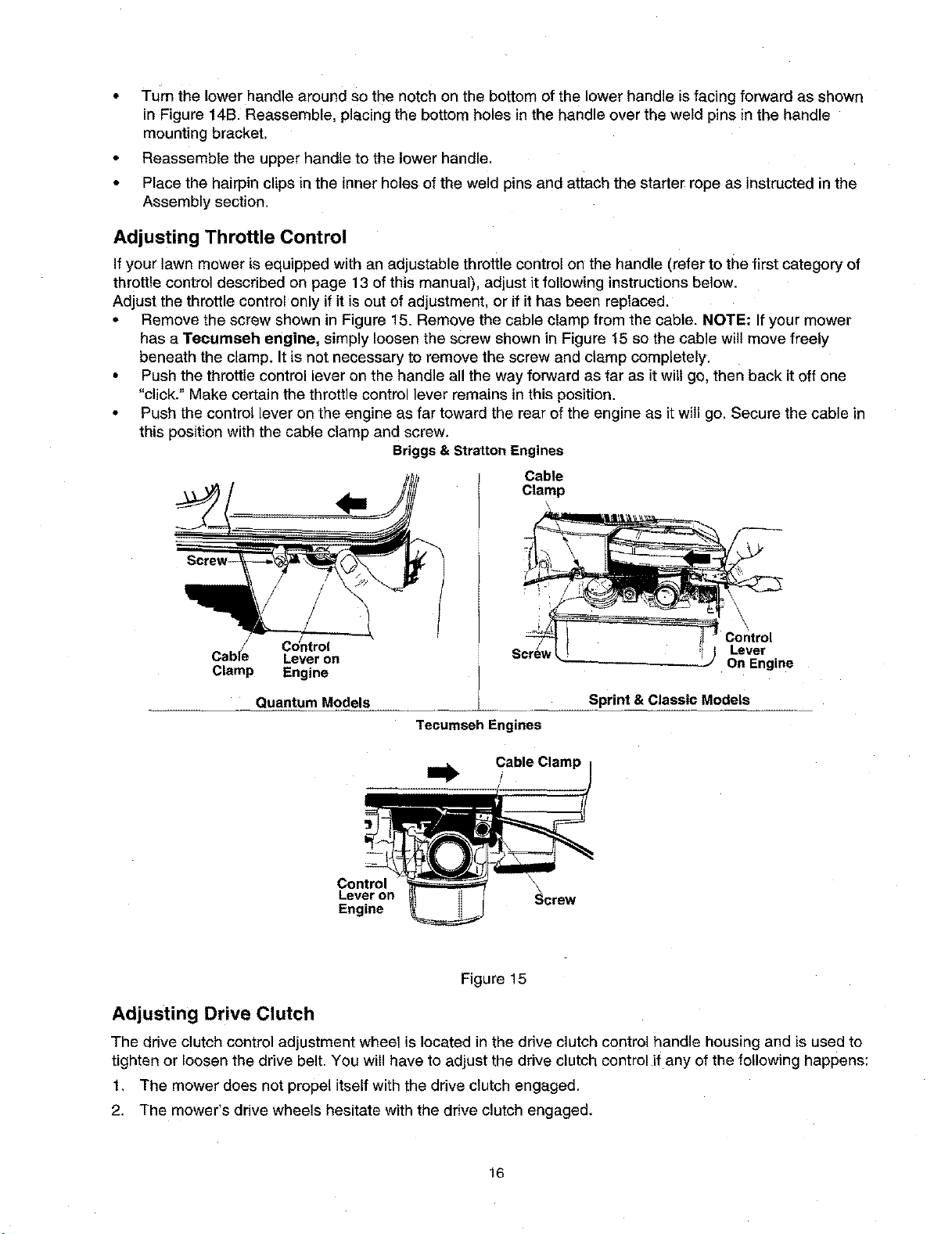
- Remove the screw shown in Figure 15. Remove the cable clamp from the cable. NOTE: If your mower
has a Teeumseh engine, simply loosen the screw shown in Figure 15 so the cable will move freely
beneath the clamp. It is not necessary to remove the screw and clamp completely.
• Push the throttle control lever on the handle all the way forward as far as it will go, then back it off one
"click." Make certain the throttle control lever remains in this position.
• Push the control lever on the engine as far toward the rear of the engine as it will go. Secure the cable in
this position with the cable clamp and screw.
Briggs& StrattonEngines
Cable
Clamp
Cab(e Lever on
Clamp Engine
Quantum Models
Tecumseh Engines
Lever
On Engine
Sprint & Classic Models
Cable Clamp
/
,f
Control
Lever on
Engine
Figure 15
Adjusting Drive Clutch
The drive clutch control adjustment wheel is located in the drive clutch control handle housing and is used to
tighten or loosen the drive belt. You will have to adjust the drive clutch control if any of the following happens:
1, The mower does not propel itself with the drive clutch engaged,
2, The mower's drive wheels hesitate with the drive clutch engaged,
16
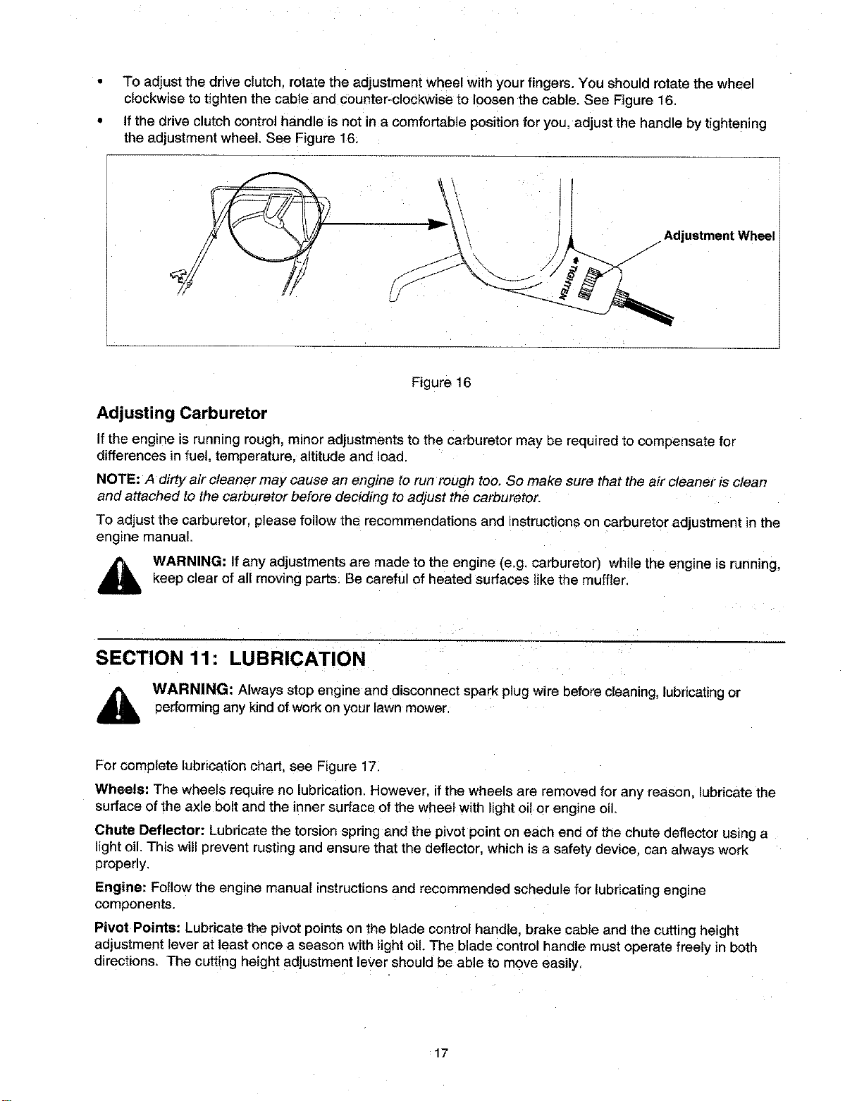
To adjust the drive clutch, rotate the adjustment wheel with your fingers. You should rotate the wheel
clockwise to tighten the cable and counter-clockwise to loosen the cable. See Figure 16.
If the drive clutch control handle is not in a comfortable position for you, adjust the handle by tightening
the adjustment wheel. See Figure 16.
/_ JAdjustment Wheel
Figure 16
Adjusting Carburetor
Ifthe engine is running rough, minor adjustments to the carburetor may be required to compensate for
differences in fuel, temperature, altitude and Ioac
NOTE: A dirty air cleaner may cause an engine to run rough too, So make sure that the air cleaner is clean
and attached to the carburetor before deciding to adjust the carburetor.
To adjust the carburetor, please follow the recommendations and instructionson carburetor adjustment in the
eng=ne manual
WARNING: If any adjustments are made to the engine (e.g. carburetor) while the engine is running,
keep clear of all moving parts. Be careful of heated surfaces like the muffler.
SECTION 11: LUBRICATION
_IL ARNING: Always stop engine and disconnect spark plug wire before cleaning, lubricating or
performing any kind of work on your lawn mower.
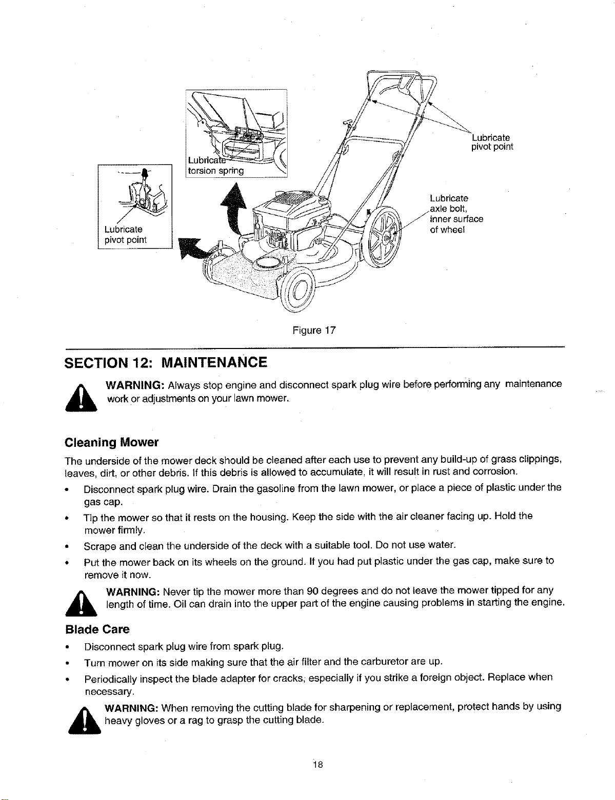
For complete lubrication chart, see Figure 17.
Wheels= The wheels require no lubrication. However. ifthe wheels are removed for any reason, lubricate the
surface of the axle bolt and the inner surface of the wheel with light oil or engine oil,
Chute Deflector: Lubricate the torsion spring and the pivot point on each end of the chute deflector us=ng a
light oil. This will 0revent rusting and ensure that the deflector, which is a safety device, can always work
properly.
Engine: Follow the engine manual instructionsand recommended schedule for lubricating engine
components.
Pivot Points: Lubricate the pivot points on the blade control handle, brake cable and the cutting height
adjustment lever at least once a season with light oil. The blade control handle must operate freely in both
directions. The cutting height adjustment lever should be able to move easily,
17
Lubricate
pivot point
ILUbtors_
Lubricate
pivot point
Lubricate
jaxle bolt,
inner surface
of wheel
Figure 17
SECTION 12: MAINTENANCE
WARNING: Always stop engine and disconnect spark plug wire before performing any maintenance
work or adjustments on your lawn mower.
Cleaning Mower
The underside of the mower deck should be cleaned after each use to prevent any build-up of grass clippings,
leaves, dirt, or other debris. If this debris is allowed to accumulate, it will result in rust and corrosion.
• Disconnect spark plug wire. Drain the gasoline from the lawn mower, or place a piece of plastic under the
gas cap.
• Tip the mower so that it rests on the housing. Keep the side with the air cleaner facing up. Hold the
mower firmly.
• Scrape and clean the underside of the deck with a suitable tool. Do not use water.
• Put the mower back on its wheels on the ground. If you had put plastic under the gas cap, make sure to
remove it now.
,_ WARNING: Never tip the mower more than 90 degrees and do not leave the mower tipped for any
length of time. Oil can drain into the upper part of the engine causing problems in starting the engine.
Blade Care
• Disconnect spark plug wire from spark plug.
• Turn mower on its side making sure that the air filter and the carburetor are up.
• Periodically inspect the blade adapter for cracks; especially if you strike a foreign object. Replace when
necessary.
_ ARNING: When removing the cutting blade for sharpening or replacement, protect hands by using
heavy gloves or a rag to grasp the cutting blade.
18
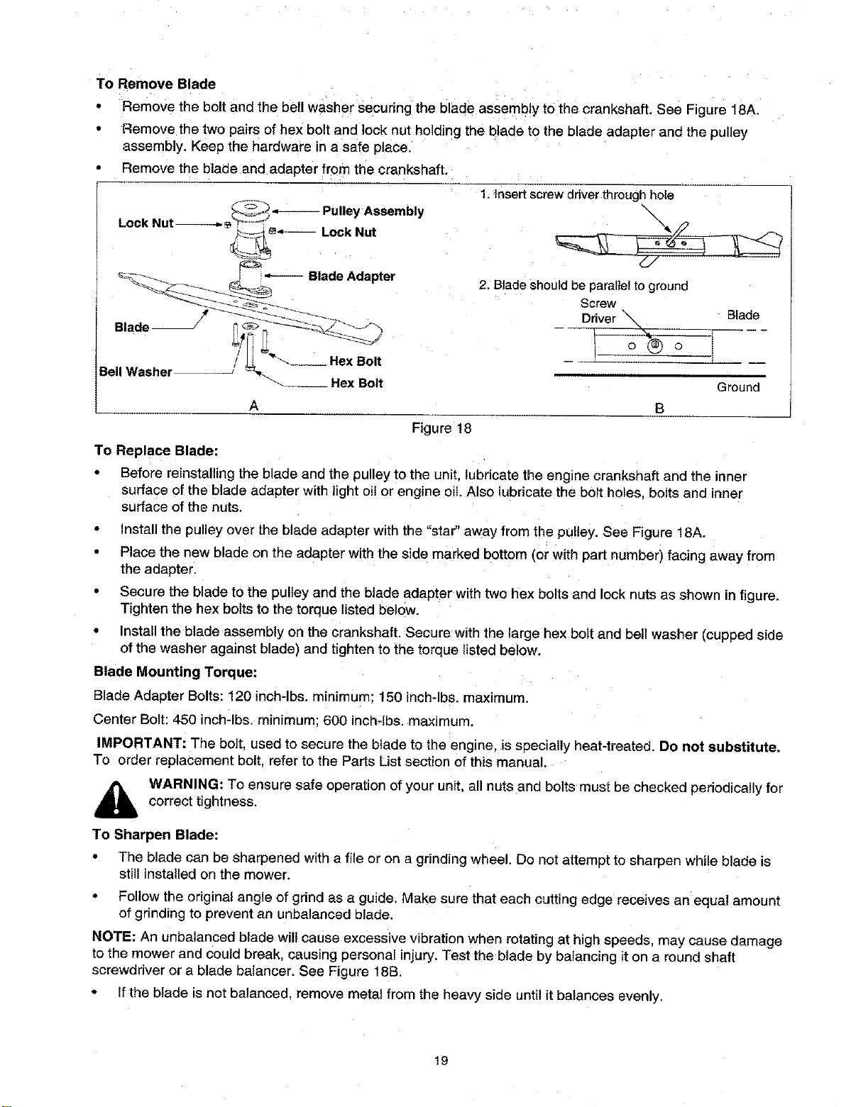
To Remove Blade
Remove the Dolt and the bell washer securing the blade assembly to the crankshaft. See Figure 18A.
Remove the two pairs of hex bolt and lock nut holding the blade to the blade adapter and the pulley
assembly. Keep the hardware in a safe place.
Remove the blade and adapter from the crankshaft
_Pulley Assembly
Lock Nut ÷'_-
_Lock Nut
1. Insert screw driver through hole
\
Blade Adapter 2. Blade should be parallel to ground
Screw
Driver _ Blade
Blade
Bell Washer _-__ He){Bolt Ground
A B
Figure 18
To Replace Blade:
Before reinstalling the blade and the pulley to the unit. lubricate the engine crankshaft and the inner
surface of the blade adapter with light oil or engine oil. Also lubricate the bolt holes, bolts and inner
surface of the nuts.
Install the pulley over the blade adapter with the "star" away from the pulley. See Figure 18A.
Place the new blade on the adapter with the side marked bottom (or with part number) facing away from
the adapter.
Secure the blade to the pulley and the blade adapter with two hex bolts and lock nuts as shown in figure.
Tighten the hex bolts to lhe torque listed below.
• Install the blade assembly on the crankshaft. Secure with the large hex bolt and bell washer _cupped side
of the washer against blade) and tighten to the torque listed below.
Blade Mounting Torque:
Blade Adapter Bolts: 120 inch-lbs, minimum; 150 inch-lbs, maximum.
Center Bolt: 450 inch-lbs, mintmum; 600 inch-lbs, maximum.
IMPORTANT: The bolt. used to secure the blade to the engine, Is specially heat-treated. Do not substitute.
To order replacement bolt. refer to the Parts List section of this manual.
,_ WARNING: To ensure safe operation of your unit, all nuts and bolts must be checked periodically for
correct tightness.
To Sharpen Blade:
• The blade can be sharpened with a file or on a grinding wheel. Do not attempt to sharpen while blade is
still installed on the mower.
- Follow the original angle of grind as a guide, Make sure that each cutting edge receives an equal amount
of grinding to prevent an unbalanced blade.
NOTE: An unbalanced blade will cause excessive vibration when rotating at high speeds, may cause damage
to the mower and could break, causing personal injury. Test the blade by balancing it on a round shaft
screwdriver or a blade balancer. See Figure 18B.
• If the blade is not balanced, remove metal from the heavy side until it balances evenly.
19
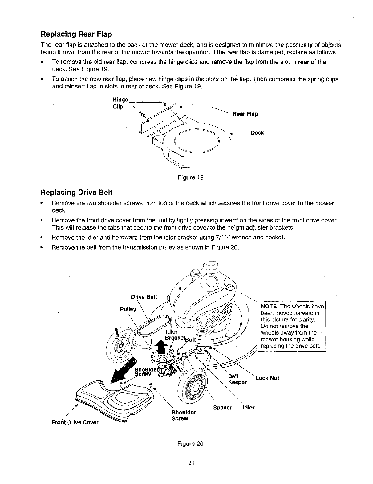
Replacing Rear Flap
The rear flap is attached to the back of the mower deck, and is designed to minimize the possibilityof objects
being thrown from the rear ofthe mower towards the operator. If the rear flap isdamaged, replace as follows.
• To remove the old rear flap, compress the hinge clips and remove the flap from the slot in rear of the
deck. See Figure 19.
• To attach the new rear flap, place new hinge clips in the slots on the flap. Then compress the spring clips
and reinsert flap in slots in rear of deck, See Figure 19.
Hinge
Clip _ _'_
_Rear Flap
Figure 19
Replacing Drive Belt
•Remove the two shoulder screws from top of the deck which secures the front drive cover to the mower
deck.
•Remove the front drive cover from the unit by lightly pressing inward on the sides of the front drive cover.
This will release the tabs that secure the front drive cover to the height adjuster brackets.
• Remove the idler and hardware from the idler bracket using 7/16" wrench and socket.
• Remove the belt from the transmission pulley as shown in Figure 20.
NOTE: The wheels have
been moved forward in
this picture for clarity.
Do not remove the
wheels away from the
mower housing while
replacing the drive belt.
Lock Nut
Keeper
Front Drive Cover
Shoulder
Screw
Spacer Idler
Figure 20
2o
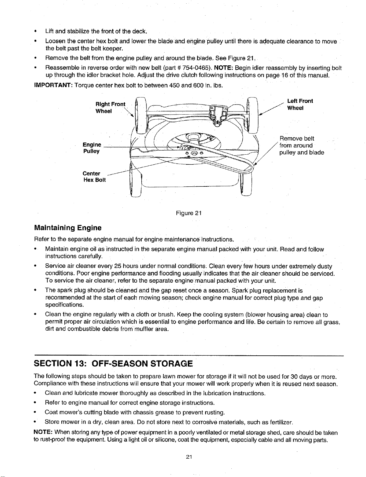
Lift and stabilize the front of the deck.
• Loosen the center hex bolt and lower the blade and engine pulley until there is adequate clearance to move
the belt past the belt keeper.
Remove the belt from the engine pulley and around the blade. See Figure 21.
Reassemble in reverse order with new belt (part # 754-0465), NOTE: Begin idler reassembly by inserting bolt
up through the idler bracket hole. Adjust the drive clutch following instructions on page 16 of this manual.
IMPORTANT: Torque center hex bolt to between 450 and 600 in. Ibs.
Right Front _--_I - - -_'_-_- __1 Left Front
Wheel \_H i(__l _::::::::_; :_ i._ "fj Wheel
/_'--_(/ _ _ '_ Remove belt
Engine /from around
Pulley "'_ _\ rt___ /pulley and blade
Center _ _'_ _ "/
Hex Bolt _ _J'_ 1
J
Figure 21
Maintaining Engine
Refer to the separate engine manual for engine maintenance instructions.
Maintain engine oil as instructed in the separate engine manual oacked with your unit. Read and follow
instructions carefully,
Service air cleaner every 25 hours under normal conditions. Clean every few hours under extremely dusty
conditions. Poor engine performance and flooding usually indicates that the air cleaner should be serviced
To service the air cleaner, refer to the separate engine manual packed with your unit.
The spark plug should be cleaned and the gap reset once a season. Spark plug replacement is
recommended at the start of each mowing season: check engine manual for correct plug type and gap
specifications.
• Clean the engine regularly with a cloth or brush. Keep the cooling system (blower housing area) clean to
permit proper air circulation which is essential to engine performance and life. Be certain to remove all grass,
dirt and combustible debris from muffler area.
SECTION 13: OFF-SEASON STORAGE
The following steps should be taken to prepare lawn mower for storage if it will not be used for 30 days or more.
Compliance with these instructionswill ensure that your mower willwork properly when itis reused next season.
• Clean and lubricate mower thoroughly as described in the lubrication instructions.
• Refer to engine manual for correct engine storage instructions.
• Coat mower's cutting blade with chassis grease to prevent rusting.
•Store mower in adry, clean area. Do not store next to corrosive materials, such as fertilizer.
NOTE: When storing any type of power equipment in a poorlyventilated or metal storage shed, care should be taken
to rust-proof the equipment. Using a light oil or silicone, coatthe equipment, especially cable and all moving parts.
21
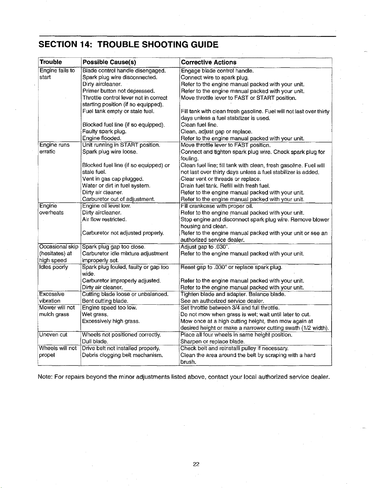
SECTION 14: TROUBLE SHOOTING GUIDE
Corrective Actions
Trouble
Engine fails to
start
Engine runs
erratic
Engine
overheats
iOccasional skip
(hesitates) at
high speed
Idles poorly
Excessive
vibration
Mower will not
imulch grass
Possible Cause(s)
Blade control handle disengaged.
Spark plug wire disconnected.
Dirty airoleaner.
Primer button not depressed.
Throttle control lever not in correct
starting position (if so equipped).
Fuel tank empty or stale fuel.
Blocked fuel line (if so equipped),
Faulty spark plug.
Engine flooded.
Unit running in START position.
Spark plug wire loose,
Blocked fuel Iine (if so equipped) or
stale fuel.
Vent in gas cap plugged.
Water or dirt in fuel system.
Dirty air cleaner.
Carburetor out of adjustment.
Engine oil level low.
Dirty aircleaner.
Air flow restricted.
Carburetor not adjusted properly.
Spark plug gap too close.
Carburetor idle mixture adjustment
improperly set.
Spark plug fouled, faulty or gap too
wide.
Carburetor improperly adjusted.
Dirty air cleaner,
Cutting blade loose or unbalanced.
Bent cutting blade.
Engine speed too low,
Wet grass,
Excessively high grass.
Uneven cut Wheels not positioned correctly.
Dull blade.
Wheels will not Drive belt not installed properly,
)ropel Debris clogging belt mechanism.
Engage blade control handle,
Connect wire to spark plug.
Refer to the engine manual packed with your unit,
Refer to the engine manual packed with your unit_
Move throttle lever to FAST or START position.
Fill tank with clean fresh gasoline. Fuel will not last over thirty
days unless a fuel stabilizer is used.
Clean fuel line.
Clean, adjust gap or replace.
Refer to the engine manual packed with your unit.
Move throttle lever to FAST position,
Connect and tighten spark plug wire. Check spark plug for
fouling,
Clean fuel line; fill tank with clean, fresh gasoline. Fuel will
not last over thirty days unless a fuel stabilizer is added,
Clear vent or threads or replace.
Drain fuel tank, Refill with fresh fuel.
Refer to the engine manual packed with your unit.
Refer to the engine manual packed with your unit.
Fill crankcase with proper oil.
Refer to the engine manual packed with your unit.
Stop engine and disconnect spark plug wire, Remove blower
housing and clean,
Refer to the engine manual packed with your unit or see an
authorized service dealer.
Adjust gap to .030".
Refer to the engine manual packed with your unit,
Reset gap to .030" or replace spark plug.
Refer to the engine manual packed with your unit.
Refer to the engine manual packed with your unit.
Tighten blade and adapter. Balance blade.
See an authorized service dealer.
Set throttle between 3/4. and full throttle.
Do not mow when grass is wet; wait until later to cut.
Mow once at a high cutting height, then mow again at
desired height or make a narrower cutting swath (1/2 width).
Place all four wheels in same height position.
Sharpen or replace blade,
Check belt and reinstalll pulley if necessary,
Clean the area around the belt by scraping with a hard
brush.
Note: For repairs beyond the minor adjustments listed above, contact your local authorized service dealer.
22
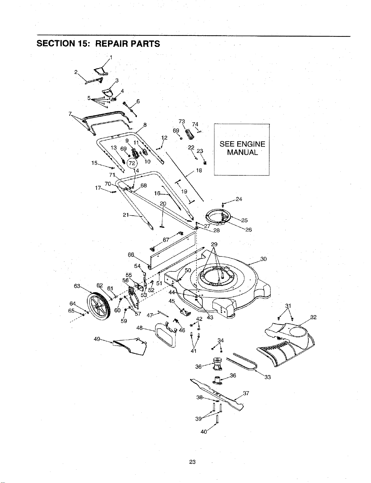
SECTION 15: REPAIR PARTS
71
SEE ENGINE
MANUAL
55
23
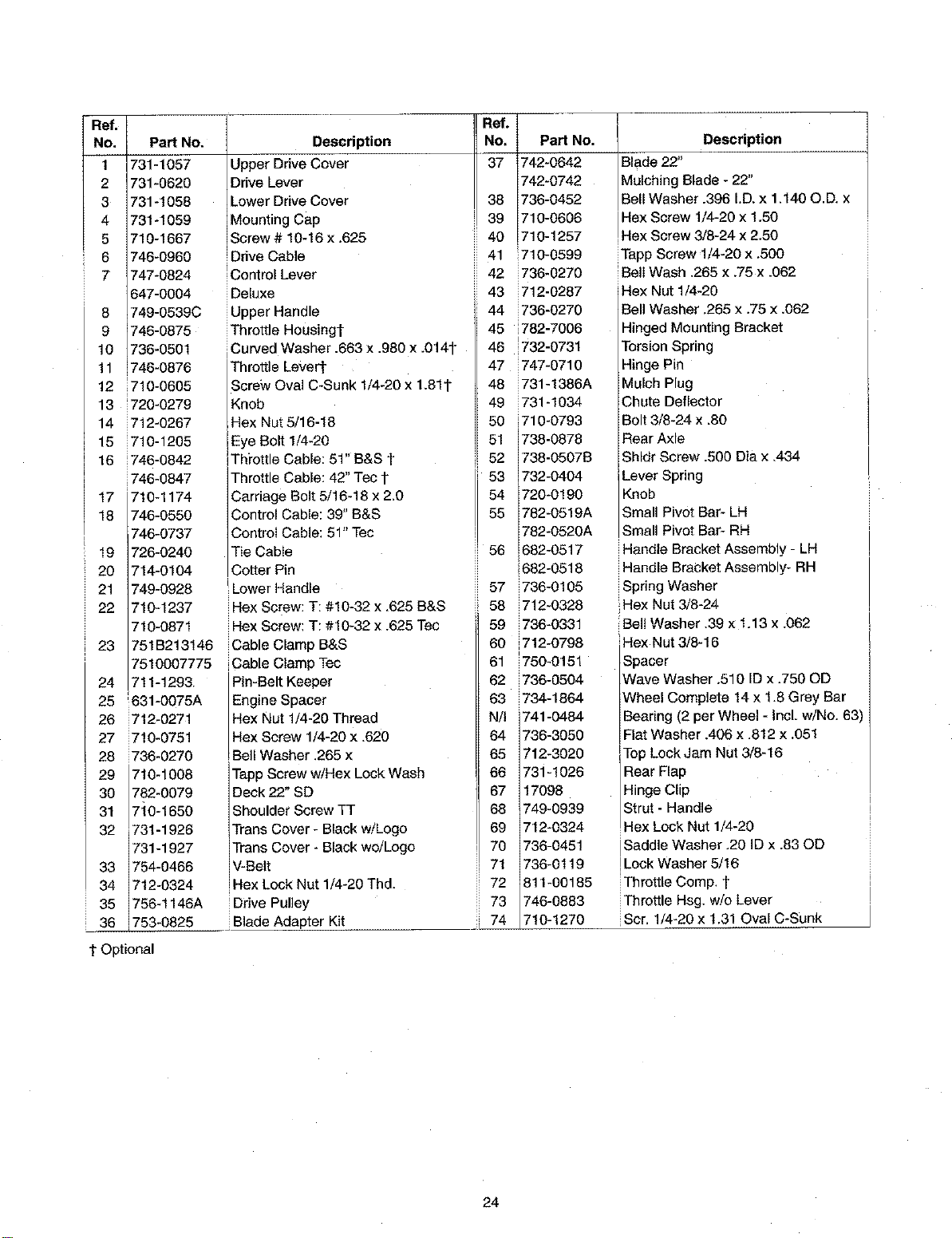
Ref.
No,
1
2
3
4
5
6
7
8
9
10
11
12
13
14
15
16
17
18
19
2O
21
22
23
24
25
26
27
28
29
30
31
32
33
34
35
36
PaN No.
731-1057
731-0620
731-1 O58
731-1059
710-1667
746-0960
747-0824
647-0004
749-0539C
746-0875
736-0501
746-0876
710-0605
720-0279
712-0267
710-1205
746-0842
i746-0847
710-1174
746-0550
746-0737
726-0240
714-0104
749-0928
710-1237
710-0871
751B213146
7510007775
711-1293
631-0075A
i712-0271
710-0751
736-0270
710-1008
782-0079
710-1650
731-1926
731-1927
754-0466
712-0324
756-1146A
753-0825
Description
Upper Drive Cover
Drive Lever
Lower Drive Cover
Mounting Cap
Screw # 10-16 x ,625
Ddve Cable
'Control Lever
Deluxe
Upper Handle
Throttle Housingl-
Curved Washer .663 x .980 x .014t"
Throttle Lever[
Screw Oval C-Sunk 1/4-20 x 1.81t
Knob
Hex Nut 5/16-18
Eye Bolt 1/4-20
Th_'ottle Cable: 51" B&S t
Throttle Cable: 42" Tec 1"
Carriage Belt 5/16-18 x 2,0
Control Cable: 39" B&S
Controi Cable: 51" Tec
Tie CabIe
Cotter Pin
'Lower Handle
Hex Serew: T: #10-32 x ,625 B&S
Hex Screw: T: #10-32 x .625 Tec
Cable Clamp B&S
Cab e C amp Tec
Pin-Belt Keeper
Engine Spacer
Hex Nut 1/4-20 Thread
IHex Screw 1/4-20 X .620
Bel! Washer ,265 x
Tapp Screw w!Hex Lock Wash
Deck 22" SD
Shoulder Screw TT
Trans Cover - Black w/Logo
Trans Cover - Black we/Logo
V-Belt
Hex Lock Nut 1/4-20 Thd.
iDrive Pulley
Blade Adapter Kit
Ref.
No,
38
39
40
41
42
43
44
45
46
47
48
49
50
51
52
53
54
55
56
57
58
59
60
61
62
63
N/I
64
65
66
67
68
69
70
71
72
73
: 74
PaN No.
742-0642
742-0742
736-0452
710-0606
710-1257
i710-0599
i736-0270
i712-0287
i736-0270
782-7006
1732-0731
i747-0710
i731-1386A
i731-1034
i710-0793
738-0878
738-0507B
732-0404
720-0190
782-0519A
782-0520A
682-0517
1682-0518
i736-0105
i712-0328
736-0331
712-0798
i750-0151
i736-0504
i734-1864
741-0484
736-3050
712-3020
731-1026
17098
749-0939
712-0324
736-045!
736-0119
811-00185
746-0883
710-1270
Description
Blade 22"
Mulching Blade - 22"
Bell Washer .396 I.D. x 1.140 O.D. x
Hex Screw 1/4-20 x 1.50
Hex Screw 3/8-24 x 2.50
Tapp Screw 1/4-20 x ,500
Bell Wash .265 x.75 x .062
Hex Nut 1/4-20
Bell Washer .265 x.75 x.062
Hinged Mounting Bracket
Torsion Spring
Hinge Pin
Mulch Plug
Chute Deflector
Bolt 3/8-24 x .80
Rear Axle
Shldr Screw .500 Dia x ,434
Lever Spring
Knob
Small Pivot Bar- LH
Small Pivot Bar- RH
Handle Bracket Assembly - LH
Handle Bracket Assembly- RH
Spring Washer
Hex Nut 3/8-24
Bali Washer .39 x 1.13 x .062
Hex Nut 3/8-16
Spacer
Wave Washer .510 ID x .750 OD
Wheel Complete 14 x 1.8 Grey Bar
Bearing (2 per Wheel - Incl. w/No. 63
Flat Washer .406 x.812 x.051
Top Lock Jam Nut 3/8-16
Rear Flap
Hinge Clip
Strut - Handle
Hex Lock Nut 1/4-20
Saddle Washer .20 ID x .83 OD
Lock Washer 5/16
Throttle Comp. t
Throttle Hsg. w!o Lever
Scr. 1/4-20 x 1.31 Oval C-Sunk
t Optional
24
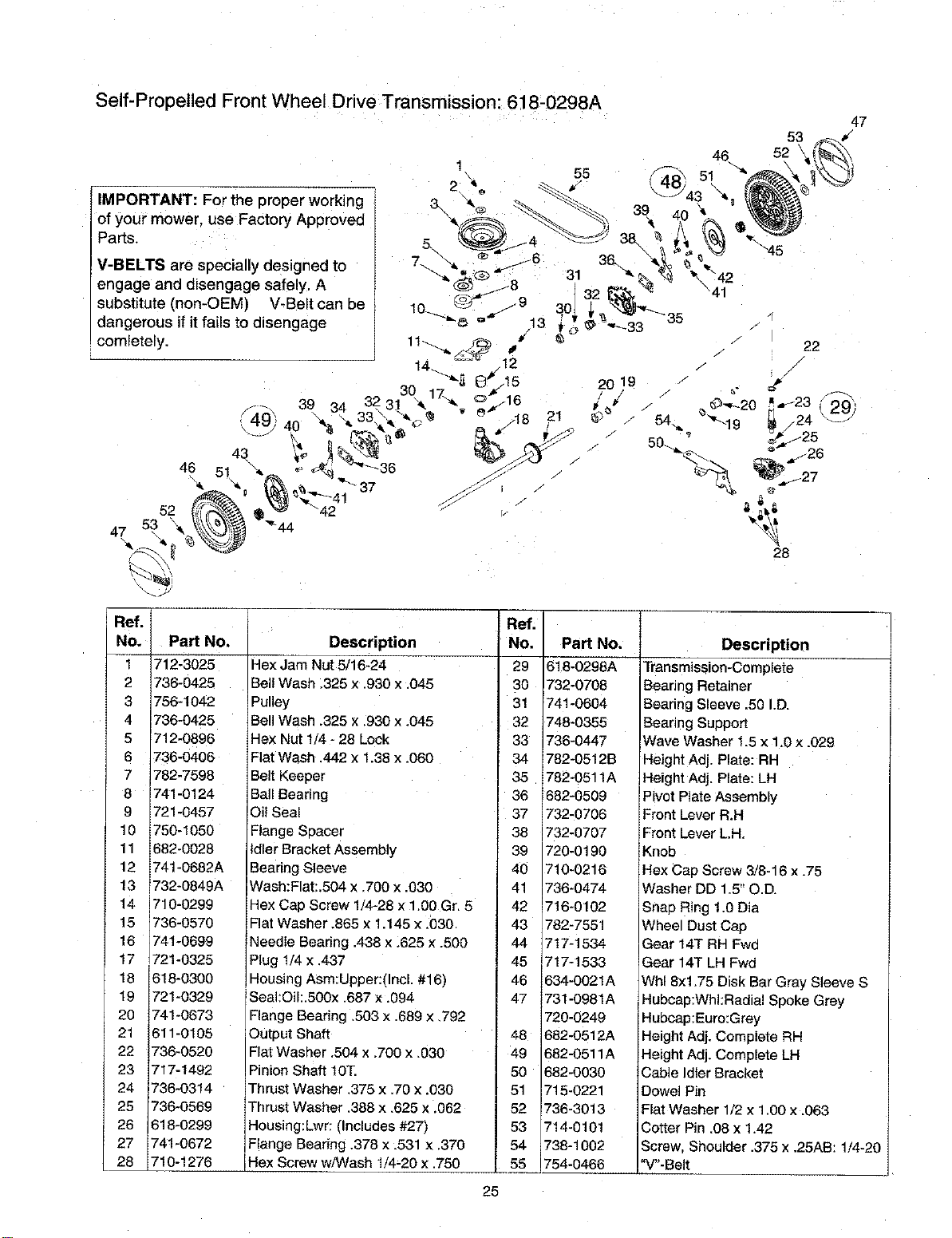
Self-Propelled Front Wheel Drive Transmission: 618-0298A
IMPORTANT: For the proper working
of your mower, use Factory Approved
Parts.
V-BELTS are specially designed to
engage and disengage safely. A
substitute (non-OEM) V-Belt can be
dangerous if it fails to disengage
comletely.
46 51
47 53 _ _'44
47
53 •
52
22
Ref.
No.
1
2
3
4
5
6
7
8
9
10
11
12
13
14
15
16
17
18
19
20
21
22
23
24
25
26
27
28
Pa_ No,
712-3025
736-0425
756-1042
736-0425
712-0896
736-0406
782-7598
741-0124
721-0457
750-1050
682-0928
741-0682A
732-0849A
710-0299
736-0570
741-0699
721-0325
618-0300
721-0329
741-0673
611-0105
736-0520
717-1492
736-0314
736-0569
618-0299
74t-0672
710-1276
Description
Hex Jam Nut 5/16-24
Bell Wash .326 x .930 x ,045
Pulley
Bell Wash .325 x :930 x .045
Hex Nut 1/4 -28 Lock
Flat Wash .442 x1.38 x .060
Belt Keeper
Ball Bearing
Oil Seal
Flange Spacer
Idler Bracket Assembly
Bearing Sleeve
Wash:Flat:.604 x .700 x .030
Hex Cap Screw 1/4-26 x 1.00 Gr, 5
Flat Washer .865 x 1.145 x _030
Needle Beadng .438 x Z625 x .500
Plug 114x .437
Housing Asm:Upper:(Incl. #16)
Seal:Oil:.500x ,687 x .094
Flange Bearing ,503 x .689 x ,792
Output Shaft
Flat Washer ,504 x.700 x ,030
Pinion Shaft 10T.
Thrust Washer .376 x .70 x .030
Thrust Washer .388 x 625 x .062
Housing:Lwr: (Includes #27)
F!ange Bearing .378 x :531 x .370
Hex Screw w/Wash 1/4-20 x .750
Ref.
NO,
29
3O
3!
32
33
34
35
36
37
38
39
40
41
42
43
44
45
46
47
48
49
5O
51
52
53
54
55
25
Part No.
618-0298A
732-0708
741-0604
748-0355
736-0447
782-0512B
782-0511A
682-0509
732-0706
732-0707
720-0190
710-0216
736-0474
716-0102
782-7551
717-1534
717-1533
634-0021A
731-0981A
720-0249
682-0512A
682-0511A
682-0030
715-0221
736-3013
714-0101
738-1002
754-0466
Description
Transmission-Complete
Bearing Retainer
Bearing Sleeve ,50 I.D.
Bearing Support
Wave Washer 1.5 x 1.0 x .029
Height Adj. Plate: RH
Height Adj. Plate: LH
Pivot Plate Assembly
Front Lever R.H
Front Lever LH.
Knob
Hex Cap Screw 3/8-16 x .75
Washer DD 1.5" O.D.
Snap Ring 1.0 Dia
Wheel Dust Cap
Gear 14T RH Fwd
Gear 14T LH Fwd
Whl 8xl .75 Disk Bar Gray Sleeve S
Hubcap:Whl:Radial Spoke Grey
Hubcap:Euro:Grey
Height Adj. Complete RH
Height Adj. Complete LH
Cable Idler Bracket
Dowel Pin
Flat Washer 1/2 x 1.00 x .063
Cotter Pin .08 x 1.42
Screw, Shoulder .375 x .25AB: 1/4-20
"V"-Belt
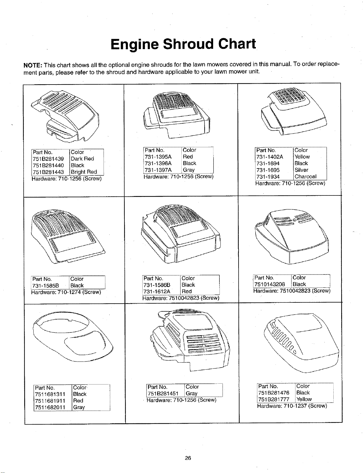
Engine Shroud Chart
NOTE: This chart shows all the optional engine shrouds for the lawn mowers covered in this manual. To order replace-
ment parts, please refer to the shroud and hardware applicable to your lawn mower unit.
Part No. Color
751B281439 Dark Red
751B281440 Black
751B281443 Bright Red
Hardware: 710-1256 (Screw)"
Part No. Color
731-1585B Black
Hardware: 710-1274 (Screw)
Pa_No. Color l
7511681311 Black
7511681911 Red i
7511682011 Gray __
!Part No: !Color
i731-1395A iRed
_731-1396A iBlack
i731-1397A iGray
Hardware:710-1256(Screw)
Pa_ No, 'Color
731-1586B Black
!731-1612A Red
Hardware:7510042823(Screw)
Part No. Color
751B281451 Gray
Hardware: 710-1256 (Screw)
Part No. ICoIor
731-1402A Yellow
731-1694 Black
731-1695 Silver
731-1934 Charcoal
Hardware: 710-1256 (Screw)
i7PartNo. Color
510143208 LBlack
Hardware: 7510042823 (Screw)
Part No. Color i
751 B281476 Black !
751B281777 Yellow I
Hardware: 710-1237 (Screw)
26

MANUFACTURER'S LIMITED WARRANTY FOR:
YARDMACHINES
For TWO YEARS from the date of retail purchase
within the United States of America, its possessions
and territories, MTD PRODUCTS INC will, at its
option, repair or replace, for the original purchaser,
free of charge, any part or parts found to be
defective in material or workmanship. This warranty
covers units which have been operated and
maintained in accordance with the operating
instructions furnished with the unit, and which have
not been subject to misuse, abuse, commercial use,
neglect, accident, improper maintenance or
alteration.
Normal wear parts or components thereof are
subject to separate terms as noted below in the "No
Fault Ninety Day Consumer Warranty" clause.
products sold or exported outside of the United
States of America, its possessions and territories,
except those sold through MTD PRODUCTS INC's
authorized channels of export distribution.
Other Warranties:
2,
3.
All normal wear part failures will be covered on this 4.
product for a period of 90 days regardless of cause.
After 90 days, but within the two year period, normal
wear parts failures will be covered ONLY IF caused
by defects in material or workmanship of OTHER 5.
component parts. Normal wear parts are defined as
batteries*, belts, blades, blade adapters, grass bags,
rider deck wheels, seats, snow thrower skid shoes,
shave plates and tires.
How to obtain service: Warranty service is
available, with proof of purchase, through your local
authorized service dealer. To locate the dealer in
your area, please check the yellow pages or contact
the Customer Service Department of MTD
PRODUCTS INC, P. Q. Box 368022, Cleveland,
Ohio 44136-9722. Phone 1 (330) 273-4683. The
return of a complete unit will not be accepted by the
factory unless prior written permission has been
extended by the Customer Support Department of
MTD PRODUCTS INC.
Transportation charges: Transportation charges
for the movement of any power equipment unit or
attachment are the responsibility of the purchaser.
Units exported out of the United States: MTD
PRODUCTS INC does not extend any warranty for
The engine or component parts thereof carry
separate warranties from their manufacturers.
Please refer to the applicable manufacturer's
warranty on these items.
*Batteries are covered by a 90-day replacement
warranty.
Log splitter pumps, valves and cylinders or
component parts thereof are covered by a one
year warranty.
All other warranties, express or implied,
including any implied warranty of merchantability
or fitness for a particular purpose, are hereby
expressly disclaimed in their entirety.
The provisions as set forth in this warranty
provide the sole and exclusive remedy of MTD
PRODUCTS INC's obligations arising from the
sales of its products, MTD PRODUCTS tNC will
not be liable for incidental or consequential loss
or damage.
How state law relates to this warranty: This
limited warranty gives you specific legal rights, and
you may also have other rights which vary from state
to state. Certain disclaimers are not allowed in some
states and therefore they may not apply to you
under all circumstances.
NOTE: This warranty does not cover routine
maintenance items such as lubricants, filters, blade
sharpening and tune-ups, or adjustments such as
brake adjustments, clutch adjustments or deck
adjustments. Nor does this warranty cover normal
deterioration of the exterior finish due to use er
exposure.