Loading ...
Loading ...
Loading ...
a. There is no option to change between manual and automatic ranges for current
measurements.
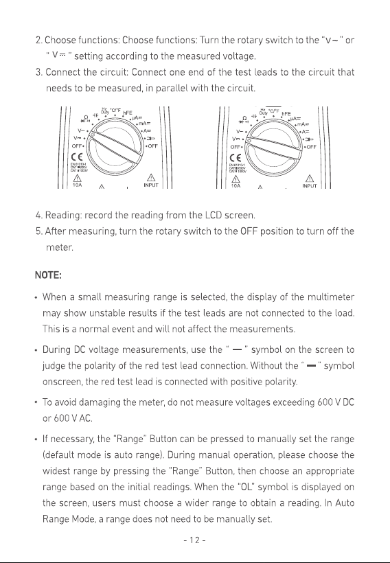
4. Connect the test leads to the source or load to be measured.
5. Read LCD display. The polarity of the red test lead will be indicated.
Resistance Measurement
1. Connect the black test lead to the “COM” jack and the red test lead to the “INPUT ” jack.
2.
Set the function switch to “ ” range.
3. Select either Auto or Manual range with the “Range” button. In manual range, if the
Resistance magnitude to be measured is not known beforehand, select the highest
range.
4. Connect the test leads to the source or load to be measured.
5. Read LCD display. The polarity of the red test lead will be indicated.
Note:
a. For resistance measurements >1MΩ, the meter may take a few seconds to stabilize
reading. This is normal for high-resistance measurement.
b. When the input is not connected, i.e. at open circuit, the symbol “OL” will be displayed as
an over range indicator.
c. Before measuring in-circuit resistance, be sure that the circuit under test has all power
removed and all capacitors are fully discharged.
Continuity Test
1. Connect the black test lead to the “COM” jack and the red test lead to the “INPUT ” jack.
2. Set the function switch to “ ” range.
3. Press the “Select” Button to select continuity measurement mode, and the symbol “ ”
will appear on the display.
4. Connect the test leads across the load to be measured.
5. If the circuit resistance is lower than about 30Ω, the built-in buzzer will sound.
Diode Test
1. Connect the black test lead to the “COM” jack and the red test lead to the “INPUT ” jack.
2. Set the function switch to “ ” range.
3. Press the “Select” Button to select continuity measurement mode, and the symbol “ ”
will appear on the display.
4. Connect the red test lead to the anode of the diode to be tested and the black test lead
to the cathode.
5. The meter will show the approximate forward voltage of the diode. If the connections are
reversed, “OL” will be shown on the display.
a. In this case, simply switch the test leads from the anode to the cathode and vice
versa.
Transistor Test
Loading ...
Loading ...
Loading ...