Loading ...
Loading ...
Loading ...
7Section 2 — ASSembly & Set-Up
C
C
(a)
(a)
(b)
(b)
Figure 2-5
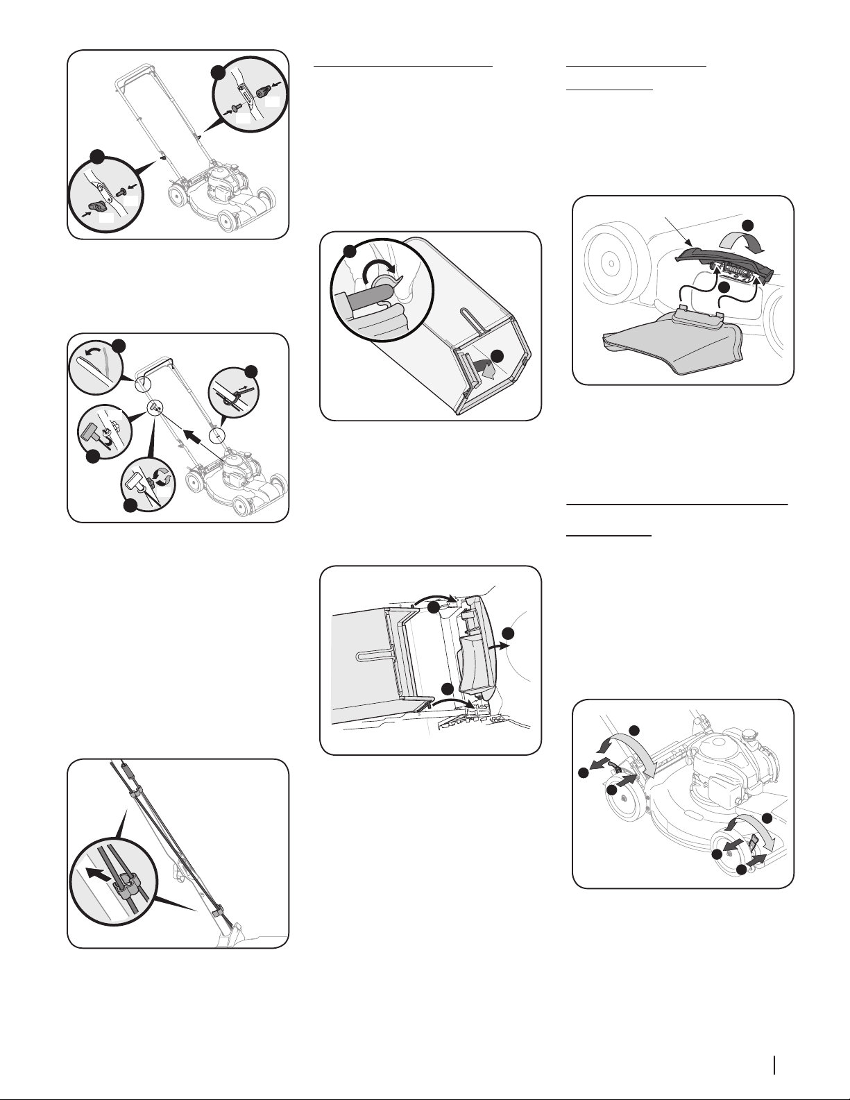
6. The rope guide is attached to the right
side of the upper handle. Loosen the
wing knob (a) which secures the rope
guide. See Figure 2-6.
D
A
B
C
(a)
(a)
Figure 2-6
a. Hold blade control against upper
handle.
b. Slowly pull starter rope handle
from engine and slip starter rope
into the rope guide.
c. Tighten rope guide
wing knob (a).
d. Use cable tie(s) to secure cable(s)
to lower handle.
NOTE: On select units, use the two cable
clips provided to secure blade control
and drive cables to lower handle as
shown in Figure 2-7.
Figure 2-7
IMPORTANT: To reduce wear and allow
for proper operation, make sure to leave
some slack in the upper portion of the
cable(s).
Grass Catcher (If Equipped)
1. Follow steps below to assemble the
grass catcher (if needed). Make certain
bag is turned right side out before
assembling (warning label will be on the
outside). See Figure 2-8.
a. Place bag over frame so that
its black plastic side is at the
bottom.
b. Slip plastic channel of grass bag
over hooks on the frame.
B
A
Figure 2-8
2. Follow steps below to attach grass
catcher. See Figure 2-9.
a. Lift mower rear discharge door.
b. Place grass catcher into the slots
in the handle brackets. Release
discharge door so that it rests on
the grass catcher.
A
B
B
Figure 2-9
To remove grass catcher, lift mower rear
discharge door. Lift grass catcher up and off
the slots in the handle brackets. Release mower
rear discharge door to allow it to close rear
opening of mower.
Side Discharge Chute
(If Equipped)
Your mower may be shipped as a mulcher.
To convert to side discharge, make sure grass
catcher (if equipped) is off the unit and mower
rear discharge door (if equipped) is closed.
1. On the side of the mower, lift the mulch
plug. See Figure 2-10.
2
1
Mulch Plug
Figure 2-10
2. Slide two hooks of side discharge
chute under hinge pin on mulch plug
assembly. Lower the mulch plug.
NOTE: Do not remove side mulch plug
at any time.
Adjustments
Cutting Height
The cutting height adjustment lever is located
above the front and rear right wheel.
1. Pull the cutting height adjustment lever
towards wheel.
2. Move lever to desired position for a
change in cutting height. See Figure 2-11
for low wheel and Figure 2-12 for high
wheel.
3
2
1
2
3
1
Lower
Lower
Higher
Higher
Low Wheel
Figure 2-11
Loading ...
Loading ...
Loading ...