Loading ...
Loading ...
Loading ...
88
how to use the vitroceramic hob
2
VITROCERAMIC HOB
The ceramic surface of the hob allows a fast transmission of heat in the vertical direction,
from the heating elements underneath the ceramic glass to the pans set on it.
The heat does not spread in a horizontal direction, so that the glass stays “cool” at only
a few centimeters from the cooking plate.
The 5 cooking zones are shown by painted disks on the ceramic surface.
IMPORTANT NOTE:
The heating elements incorporate a thermolimiter that switches the element ON/OFF
during all settings to protect the ceramic glass from overheating.
The use of incorrect pans and/or wrong pan positioning will cause the temperature limiter
to operate more frequently, resulting in a reduction of cooking performance.
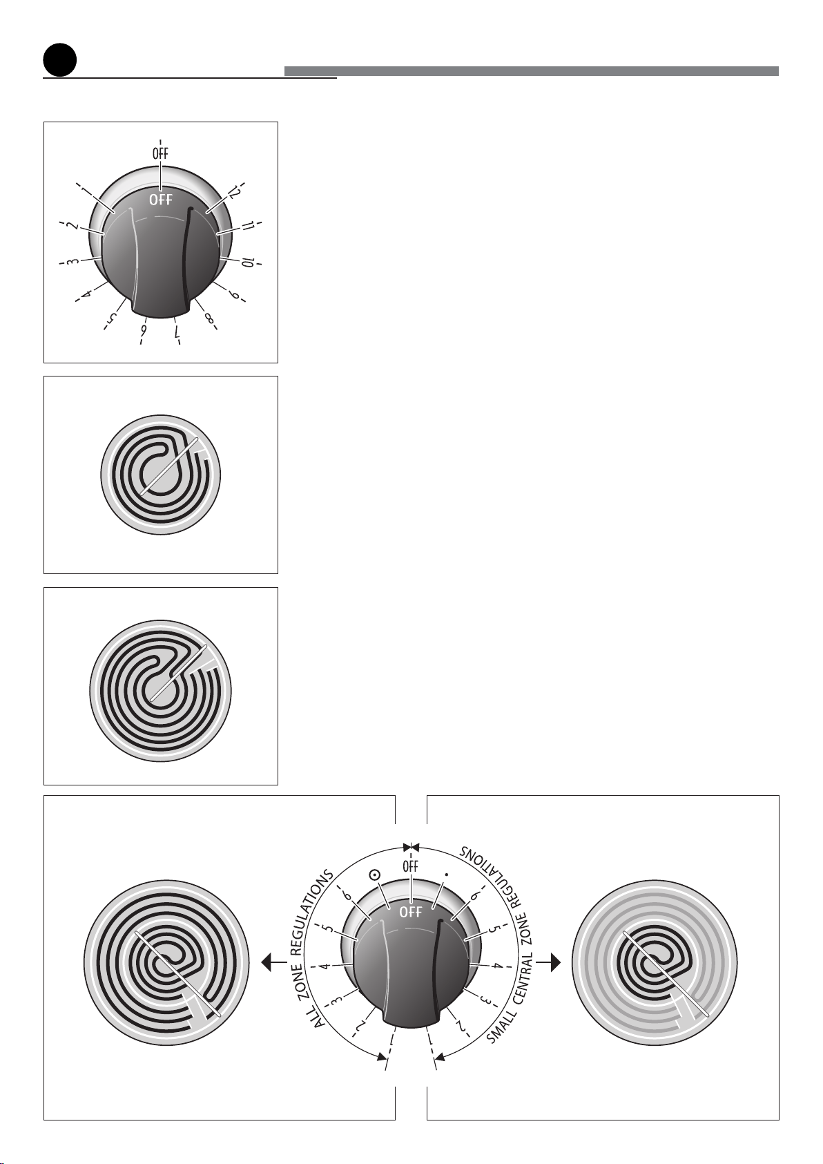
SINGLE COOKING ZONES
Incorporating the heating element (g. 2.2a or 2.2b) you can control and light up by
selecting from the 12 positions on the control knob (g. 2.1).
The heat intensity can be regulated continuously from “OFF” to “12” (max).
VERY IMPORTANT: TO SWITCH ON, ALWAYS LIGHTLY PRESS THE CONTROL
KNOB THEN TURN IT.
Check that the hob is clean and then switch on by press and turning the control knob.
DOUBLE COOKING ZONE
Incorporating 2 heating elements you can control and light up together or separately by
turning left or right the 6 positions control knob (g. 2.3).
The heat intensity can be regulated continuously from “1” to “6” (max).
VERY IMPORTANT: TO SWITCH ON, ALWAYS LIGHTLY PRESS THE CONTROL
KNOB THEN TURN IT.
SWITCH ON THE SMALL CENTRAL ZONE (g. 2.5)
Press and turn in counterclockwise direction the control knob from “1” to “6” (max).
SWITCH ON THE ALL ZONE (g. 2.4)
Press and turn in clockwise direction the control knob from “1” to “6” (max).
Fig. 2.1
Fig. 2.2a
Fig. 2.3
Fig. 2.4 Fig. 2.5
CENTRAL ZONE
2 heating element ON
FRONT RIGHT AND REAR LEFT ZONE
CENTRAL ZONE
Central heating element ON
Fig. 2.2b
FRONT LEFT AND REAR RIGHT ZONE
Loading ...
Loading ...
Loading ...