Loading ...
Loading ...
Loading ...

16
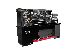
1340-1440 Lathe
Fig. 22
Tailstock clamp lever
Set-over screws
Headstock
Topslide
Tailstock
8.3 END GEAR TRAIN
Drive from headstock to gearbox is transmitted through a
gear train enclosed by the headsctock end-guard. Interme-
diate gears are carried on an adjustable swing frame (M).
Gears must be thoroughly cleaned before fitting and back-
lash maintained at 0.005 in. (0.127mm). Lubricate gears
regularly with thick oil or grease.
Fig. 23
Hexagon
nut
(by 22mm
spanner)
M
Hexagon socket head bolt
(by 6mm allen wrench)
8.4 DRIVING BELTS
To alter belt tension, remove the coverplate in back of the
headstock and adjust the two screws (X) on the hinged
motor platform. Ensure that the motor is correctly aligned
with the lathe axis.
Light finger pressure at a point midway between motor and
headstock pulleys about 3/4 in. (19mm) movement of each
belt when under correct tension.
Fig. 24
Pulley
Pulley
Motor
Belt
Press
X
8.5 SLIDE WAYS ATTENTION
Tapered gib strips are fitted to slideways of saddle cross-
lide and top (compound) slides so that any slack which
may develop can be justified.
Ensure that slideways are thoroughly cleaned and lubricat-
ed before attempting adjustment. Then reset the gibs by
loosening the rear gib screw and tightening the front screw.
Check constantly for smooth action throughout full slide
travel; avoid overadjustment which can result in increased
wear-rate and stiff or jerky action.
Fig. 25
Gib adjusters
8.6 CROSS-SLIDE NUT
This is adjustable for elimination of slack which may de-
velop in service. Reduce backlash by the cap-head screw
in the rear of the nut, then make only small adjustments
by the cap-head screw. Before operating the cross-slide,
check several times by hand to ensure smooth operation
throughout travel.
Loading ...
Loading ...
Loading ...
