Loading ...
Loading ...
Loading ...

11
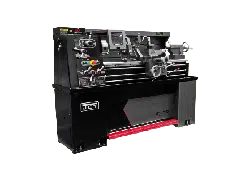
E-1340VS | E-1440VS
Fig. 8
Mounting
feet
Mounting
feet
Mounting feet
6.4 LUBRICATION CHECKS
Before operating the machine make the following important
checks:
1. That the headstock is filled to level marked on oil
sight window with Shell Tellus Oil 27.
2. That the gearbox is filled to level marked on oil sight
window with Shell Tellus Oil 27.
3. That the carriage apron is filled to level mark on oil
sight window with Shell Tonna 33.
4. In addition, apply an oil can to the points shown on
lubrication diagram which require daily oiling. Use
light machine oil or way lubricant.
Fig. 9
4
4
3
2
1
6.5 CHUCKS AND CHUCK MOUNTING
Grey-iron chucks must not be fitted on this high-
speed lathe. Use only ductile iron chucks.
When mounting chucks or faceplate, first, ensure that
spindle and chuck tapers are thoroughly cleaned and that
all cams lock in the correct positions, see figure. It may
be necessary when mounting a new chuck to reset the
camlock studs (A). To do this, remove the caphead locking
screws (B) and set each stud so that the scribed ring (C) is
flush with the rear face of the chuck - with the slot lining up
with the locking screw hole (see Fig 10).
Now mount the chuck or faceplate on the spindle nose and
tighten the three cams in turn. When fully tightened, the
cam lock line on each cam should be between the two V
marks on the spindle nose.
If any of the cams do not tighten fully within these limit
marks, remove the chuck or faceplate and readjust the
stud as indicated in the illustration. Fit and tighten the
locking screw (B) at each stud before remounting the
chuck for work.
This will assist subsequent remounting.
Note: Do not interchange chucks or faceplates
between lathes without checking for correct cam
locking beforehand.
Note: Take careful note of speed limitation when
using faceplate; 10 inch faceplates should not be
run at speeds greater than 1000 rev/min and 12
inch faceplates at not more than 770 rev/min.
Fig. 10
Cam lock line between arrows
Turn stud in one turn
Cam release datum
A
C
B
Detail of camlock stud
ass’y
Reference mark on spindle nose and chuck
Turn stud out one turn
Loading ...
Loading ...
Loading ...
