Loading ...
Loading ...
Loading ...
English 10
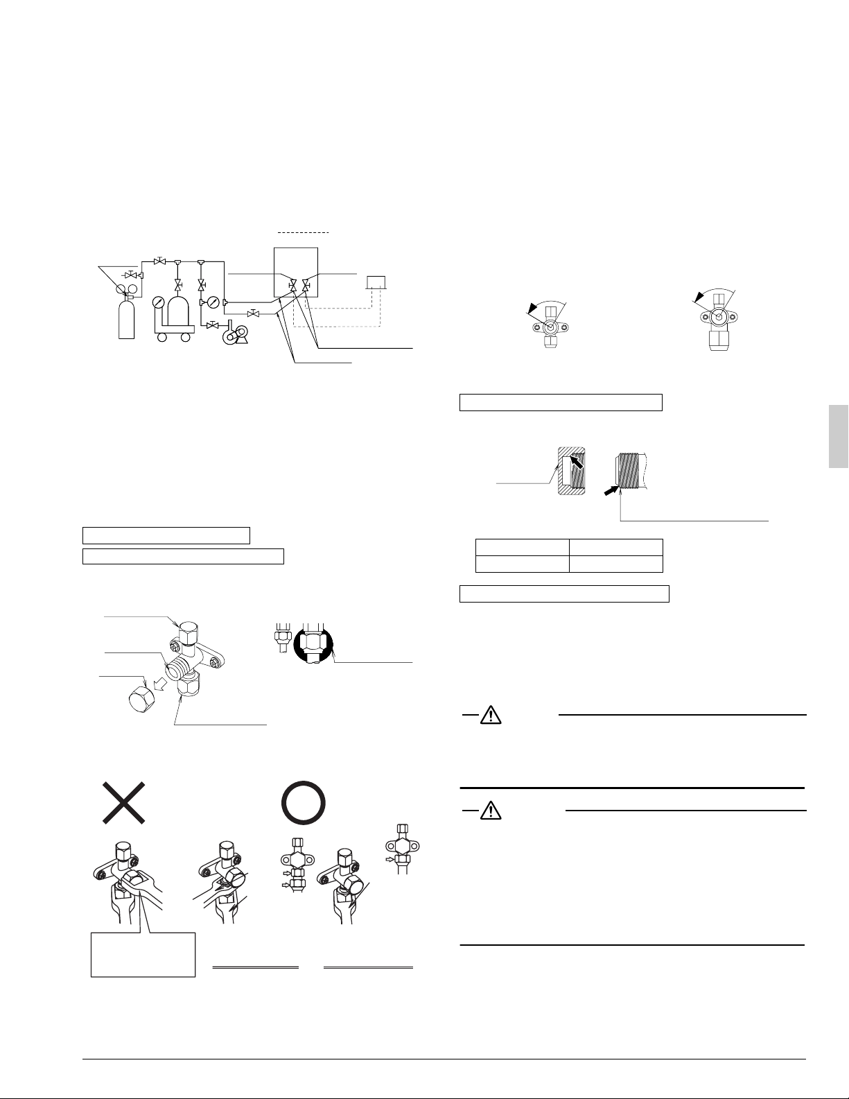
• After the vacuum drying is finished, charge the additional refrigerant
in its liquid state through the liquid stop valve service port.
Taking into account following instructions:
1.
Check that gas and liquid stop valves are closed.
2.
Charge the specified amount of refrigerant.
• If the outdoor unit is not in operation and the total amount cannot be
charged, follow the procedures for additional refrigerant charge
shown below.
• Make sure to use installation tools you exclusively use on R410A
installations to withstand the pressure and to prevent foreign materi-
als from mixing into the system.
• Procedures for charging additional refrigerant.
See the “Cautions on service” label on the back of the front panel for the
settings for operation after replenishing refrigerant.
1. Open the gas line stop valve (leaving the liquid line stop valve, valve
A in the diagram above, close) and perform the operation to add the
refrigerant.
2. Once the appropriate amount of refrigerant is in, press the confirma-
tion button (BS3) on the outdoor unit PC board (A1P), and stop oper-
ation.
3. Open the stop valves quickly (both liquid and gas line valves).
(This must be done quickly to avoid the possibility that the pipe might
burst.)
•
The figure below shows the name of each part required in handling the
stop valve
. At the time of shipment, the
stop valve
is closed.
•
If only a torque wrench is used to loosen or tighten the flare nut, the
side plate may be distorted. Make sure to fix the
stop valve
with a
spanner, then loosen or tighten the flare nut with a torque wrench.
• When it is expected that the operating pressure will be low (for exam-
ple, when cooling will be performed while the outside air temperature
is low), seal sufficiently the flare nut in the stop valve on the gas line
with silicon sealant to prevent freezing.
[Stop valve operation method]
Prepare hexagon wrenches (whose size is 4 mm and 6 mm).
How to open the stop valve
1. Insert a hexagon wrench into the valve stem, and turn the valve
stem counterclockwise.
2. When the valve stem cannot be turned any more, stop turning.
Now, the valve is open.
How to close the stop valve
1. Insert a hexagon wrench into the valve stem, and turn the valve
stem clockwise.
2. When the valve stem cannot be turned any more, stop turning.
Now, the valve is closed.
• The valve is sealed in the arrow area. Take care not to damage the
arrow area.
•
After handling the valve, make sure to tighten the valve cap securely.
• Use charge hose equipped with push in the work.
• After the work, make sure to tighten the valve cap securely.
Tightening torque.....8.5~10.3 ft·lbf
7. ELECTRIC WIRING WORK
DANGER
•
Do not ground units to water pipes, telephone wires or lightning rods
because incomplete grounding could cause a severe shock hazard
resulting in severe injury or death, and to gas pipes because a gas leak
could result in an explosion which could lead to severe injury or death.
WARNING
• Disconnect all power to unit to avoid possible electric shock
during installation.
• Use only specified wire and connect wires to terminals tightly. Be
careful that wires do not place external stress on terminals. Keep
wires in neat order so as to not to obstruct other equipment. Incom-
plete connections could result in overheating, and in worse cases,
electric shock or fire.
For the details, refer to “7-3 Power supply wiring connection pro-
cedure”.
Stop valve operation method
Cautions on handling the stop valve
Nitrogen
Dotted lines
represent
field piping
Cylinder
Stop valve service port
Vacuum pump
Weighing
scale
Charge hose
R410A
Pressure
reducing
valve
Outdoor unit
Indoor unit
Liquid line
Gas line
(Siphon system)
Valve A
Valve cap
Service port
Field piping
connection part
Valve stem
Silicon sealant
(Take care not to generate cavity.)
Stop valve of two
hangs structure
Stop valve of one
hang structure
Torque
wrench
Torque
wrench
Spanner
Spanner prohibition
to valve cap and
body part
Cautions on handling the valve cap
Liquid line Gas line
10.0~12.2 ft·lbf 16.6~20.3 ft·lbf
Cautions on handling the service port
<Liquid line>
<Gas line>
Opening direction
Opening direction
Valve cap
Stop valve
(valve cap attachment area)
01_EN_3PN07193-7L.fm Page 10 Thursday, February 16, 2012 8:22 PM
Loading ...
Loading ...
Loading ...