Loading ...
Loading ...
Loading ...
PLEASEREADCAREFULLY!Forpersonal
safety,thisproductmustbeproperlygrounded.
Groundinginstructions
The power cord of this appliance is equipped with a
3-prong (grounding) plug which mates with a standard
3-prong grounding wall receptacle to minimize the possibility
of electric shock hazard from this appliance. The customer
should have the wall receptacle and circuit checked by a
qualified electrician to make sure the receptacle isproperly
grounded and polarized.
Preferred
Not, Under
Any Circumstances,
Cut, Remove,
or Bypass the
g Prong.
Power Supply
Grounding Cord with
Type 3-Prong
Wall Grounding
Receptacle Plug
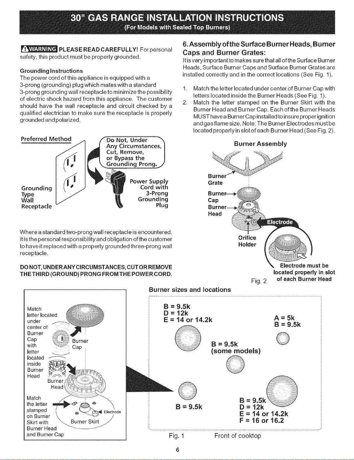
6.Assembly of the Surface Burner Heads, Burner
Caps and Burner Grates:
It isvery important to makes sure that all of the Surface Burner
Heads, Surface Burner Caps and Surface Burner Grates are
installed correctly and in the correct locations (See Fig. 1).
,
2.
Match the letter located under center of Burner Cap with
letters located inside the Burner Heads (See Fig. 1).
Match the letter stamped on the Burner Skirt with the
Burner Head and Burner Cap. Each of the Burner Heads
MUST have a Burner Cap installed to insure proper ignition
and gas flame size. Note: The Burner Electrodes must be
located properlyin slot of each Burner Head (See Fig. 2).
Burner Assembly
i
Grate
Cap
Head
Where a standard two-prong wall receptacle is encountered,
it isthe personal responsibility and obligation of the customer
to have it replaced with a properly grounded three-prong wall
receptacle.
Orifice
Holder
DO NOT, UNDERANY CIRCUMSTANCES, CUT OR REMOVE
THETHIRD (GROUND) PRONG FROM THE POWER CORD.
letter
located
inside
Burner
Head
Burner
Head _
Match
the letter
stamped
on Burner
Skirt with
Burner Head
and Burner Cap
EJectrode
Electrode must be
Jocated properly Jnslot
Fig. 2 of each Burner Head
Burner sizes and locations
B = 9.5k
D=12k
E = 14 or 14.2k A = 5k
B = 9.5k
B = 9.5k
(some models)
B = 9.5k
E = 14 or 14.2k
F = 16 or 16.2
Fig. 1 Front of cooktop
Loading ...
Loading ...