
Model AC1234-6
Recover, Recycle, Recharge Machine
for R1234yf A/C Systems
Original Instructions
Instrucciones originales
Instructions d’origine

DISCLAIMER: Information, illustrations, and specications contained in this manual are based on the latest information available
at the time of publication. The right is reserved to make changes at any time without obligation to notify any person or organization
of such revisions or changes. Further, ROBINAIR shall not be liable for errors contained herein or for incidental or consequential
damages (including lost prots) in connection with the furnishing, performance, or use of this material. If necessary, obtain additional
health and safety information from the appropriate government agencies, and the vehicle, refrigerant, and lubricant manufacturers.
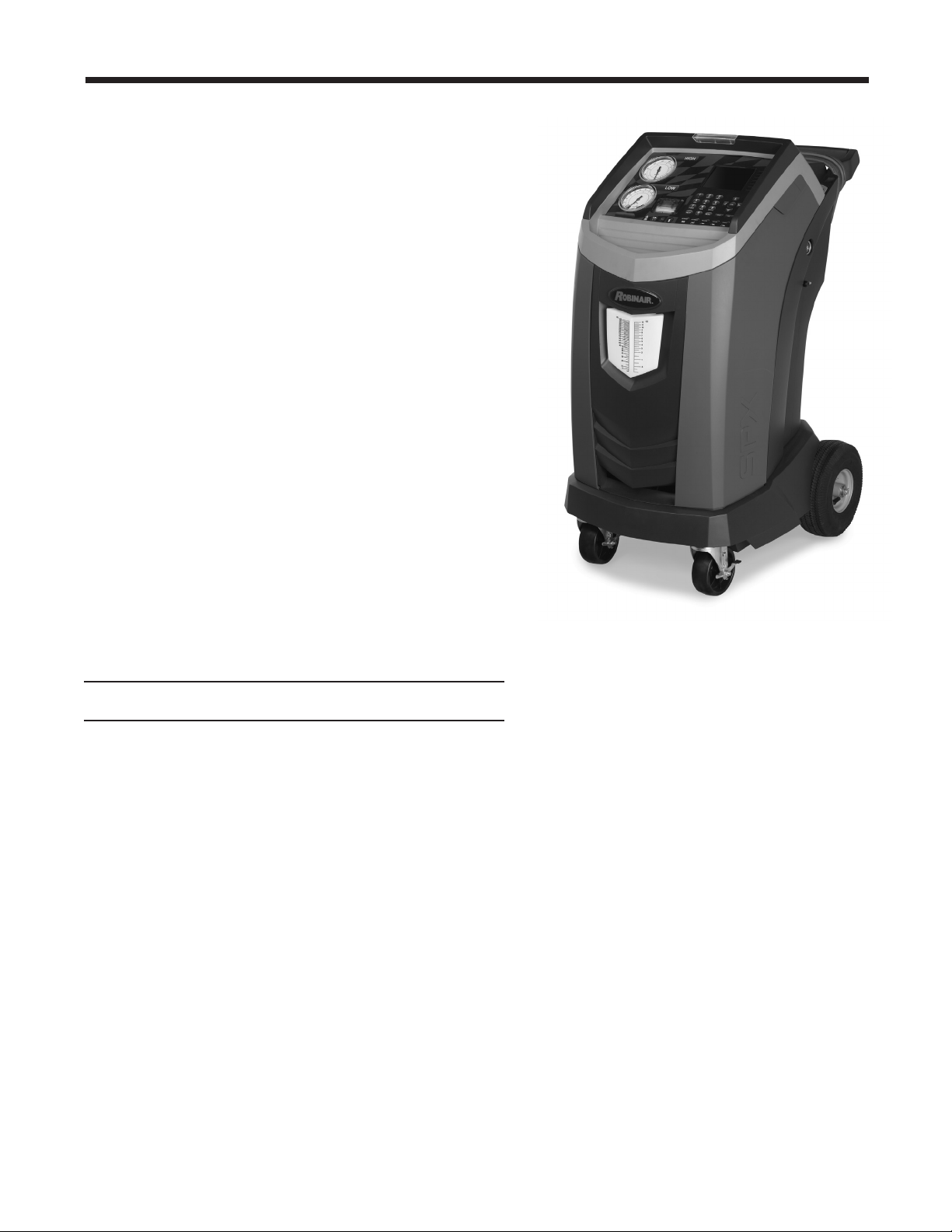
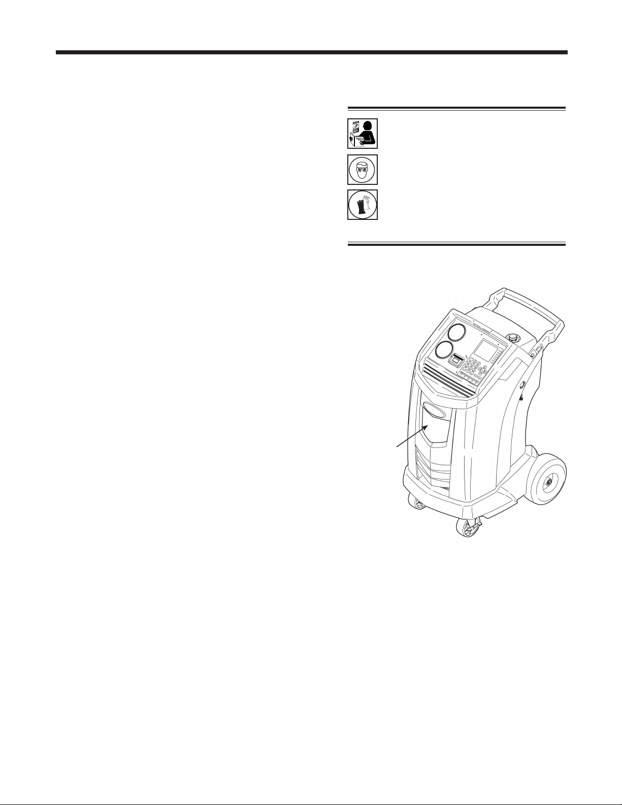
Description: Recover, recycle, and recharge machine for use
with R1234yf equipped air conditioning systems.
PRODUCT INFORMATION
Record the serial number and year of manufacture of this unit for future reference. Refer to the
product identication label on the unit for information.
AC1234-6
Serial Number: _______________________________ Year of Manufacture: ____________

1
AC1234-6 Rev. C
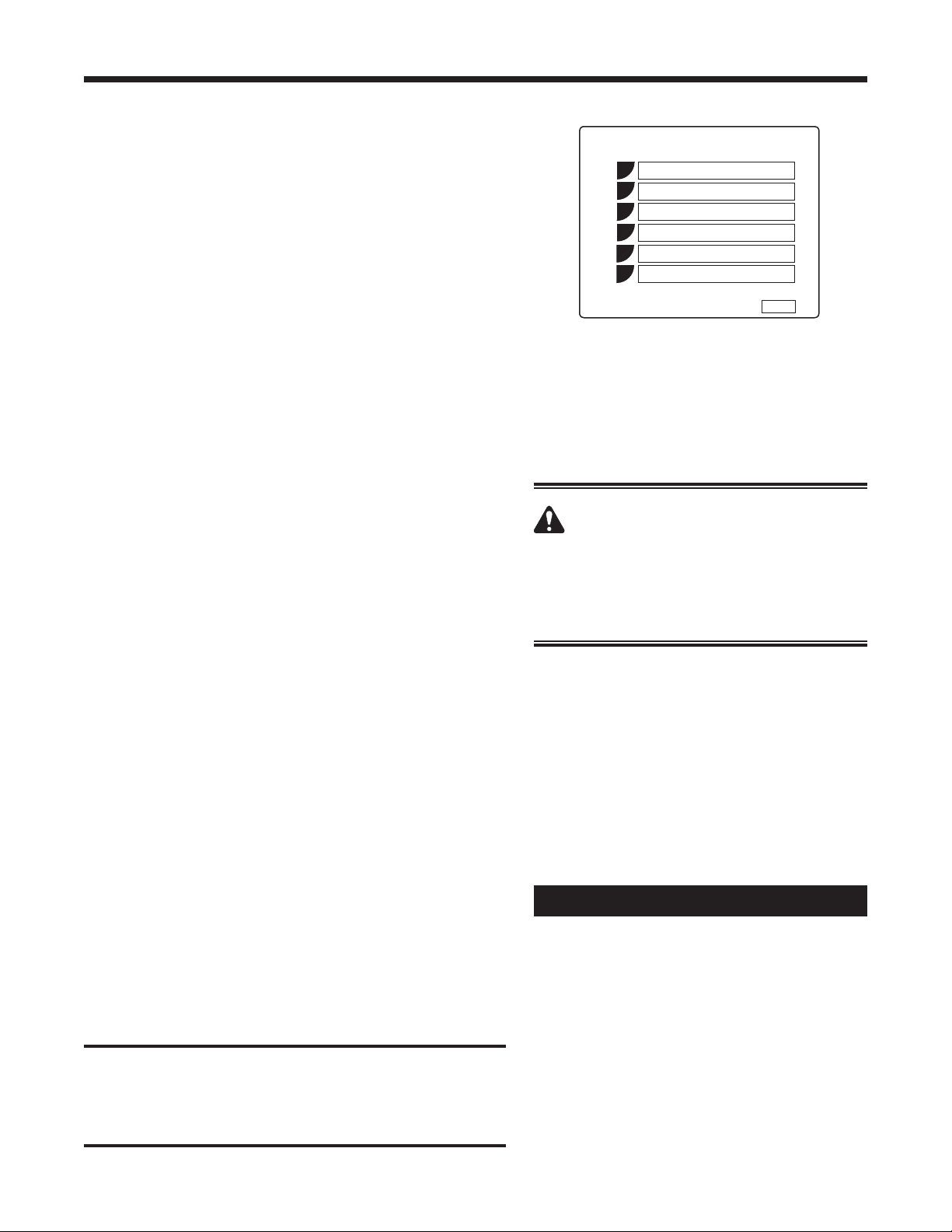
Table of Contents
Safety Precautions ...........................................2
Introduction
TechnicalSpecications.....................................5
FeaturesoftheAC1234-6 ...................................6
ControlPanelFunctions ....................................8
SetupMenuFunctions......................................9
Setup
UnpacktheAccessoryKit ..................................10
InstallOilDrainBottle .....................................10
PowerUptheMachine .................................... 11
RegistertheMachine...................................... 11
LanguageSelection .......................................12
UnitofMeasure . . . . . . . . . . . . . . . . . . . . . . . . . . . . . . . . . . . . . . . . . . 12
Date&TimeSetup........................................12
ServiceInstallationClearing ................................12
TankFillAdjustment.......................................13
Tank Filling..............................................13
GarageData ............................................14
Operating Instructions
VINEntry . . . . . . . . . . . . . . . . . . . . . . . . . . . . . . . . . . . . . . . . . . . . . . . 15
StoredData .............................................15
DiagnosticPressures......................................16
Printouts................................................16
Recovery ...............................................17
Vacuum ................................................19
HoseFlush..............................................20
Charge .................................................21
Automatic...............................................23
SystemFlush ............................................25
Maintenance
General ................................................27
ElectricalProtection .......................................27
TankFillAdjustment.......................................27
Tank Filling..............................................28
TankFillHoseFilterService ................................29
FilterChange ............................................30
RefrigerantIdentier ...................................32
CalibrationCheck ........................................32
ReplaceOxygenSensorinRefrigerantIdentier ................33
ChangeVacuumPumpOil..................................35
EditPrintHeader .........................................36
ReplacePrinterPaper .....................................36
ReplaceServiceHosesand/orServiceCouplers ...............36
Replacement Parts ..........................................37
Glossary ..................................................37
Software Flow Chart.........................................38
Troubleshooting
Messages...............................................39
Procedures..............................................41
Storage and Transportation of Equipment.......................46
2
Safety Precautions
Explanation of Safety Signal Words Used in this Manual
Thesafetysignalworddesignatesthedegree,orlevel,ofhazardseriousness.
DANGER:Indicatesanimminentlyhazardoussituationwhich,ifnotavoided,willresultindeathor
seriousinjury.
WARNING:Indicatesapotentiallyhazardoussituationwhich,ifnotavoided,couldresultindeath
orseriousinjury.
CAUTION:Indicatesapotentiallyhazardoussituationwhich,ifnotavoided,mayresultinminoror
moderateinjury.
CAUTION:Usedwithoutthesafetyalertsymbolindicatesapotentiallyhazardoussituationwhich,ifnot
avoided,mayresultinpropertydamage.
ThesesafetymessagescoversituationsRobinairisawareof.Robinaircannotknow,evaluate,oradvise
youastoallpossiblehazards.Youmustverifythatconditionsandproceduresdonotjeopardizeyour
personalsafety.
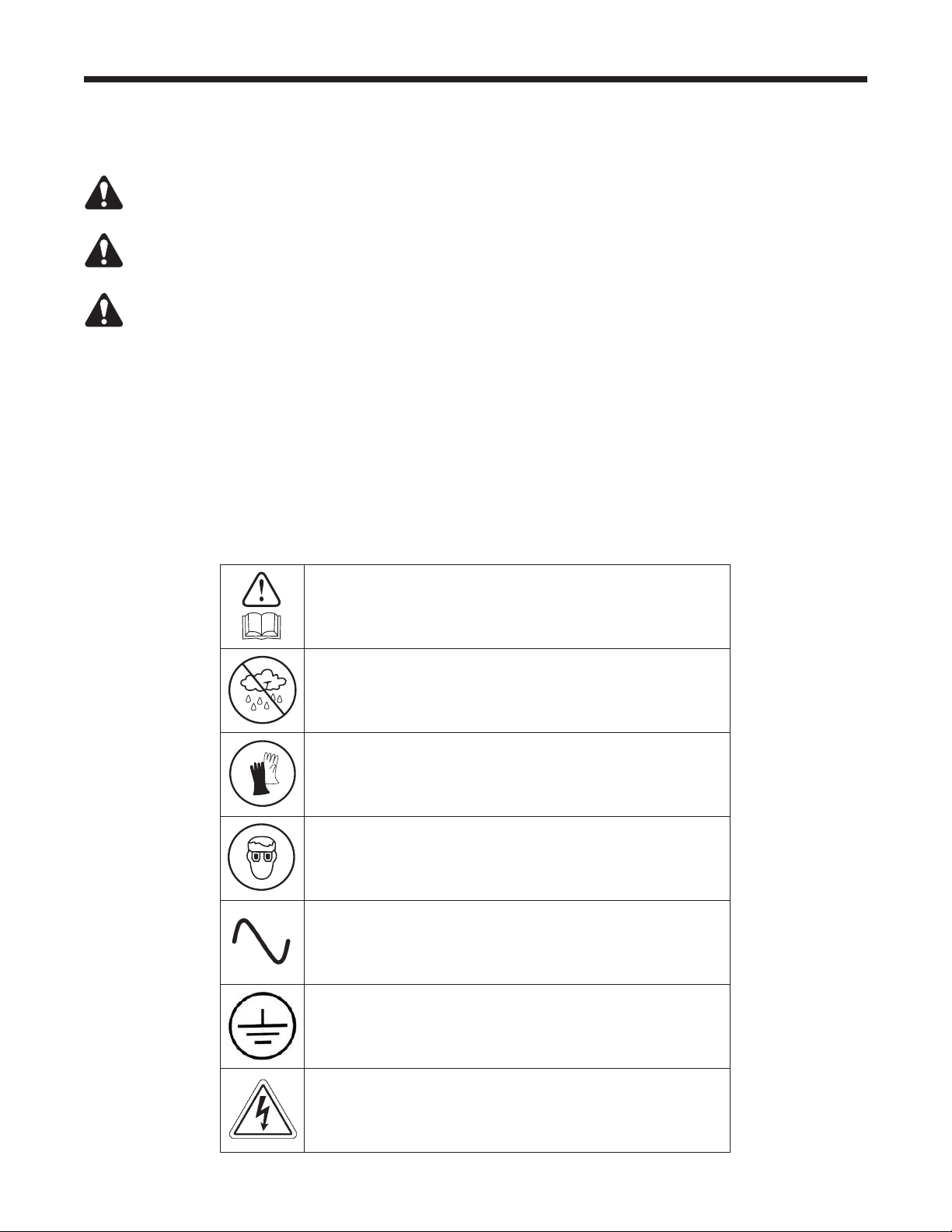
Explanation of Safety Decals Used on the Machine
Carefullyreadtheinstructions.
Donotuseinopenairincaseofrainorhighhumidity.
Weargloves.
Wearprotectiongoggles.
Alternatingvoltage.
Groundingprotection.
Electricalshockhazard.
3
AC1234-6 Rev. C
Safety Precautions
ALLOW ONLY QUALIFIED PERSONNEL TO OPERATE THE MACHINE. Beforeoperatingthemachine,
readandfollowtheinstructionsandwarningsinthismanual.Theoperatormustbefamiliarwithair
conditioningandrefrigerationsystems,refrigerants,andthedangersofpressurizedcomponents.Ifthe
operatorcannotreadthismanual,operatinginstructionsandsafetyprecautionsmustbereadanddiscussed
intheoperator’snativelanguage.
USE THE MACHINE AS OUTLINED IN THIS MANUAL.Usingthemachineinamannerforwhichitwas
notdesignedwillcompromisethemachineandnullifytheprotectionsprovided.
PRESSURIZED TANK CONTAINS LIQUID REFRIGERANT.Donotoverlltheinternalstoragevessel(ISV),
becauseoverllingmaycauseexplosionresultinginpersonalinjuryordeath.Donotrecoverrefrigerants
intononrellablecontainers;useonlytype-approvedrellablecontainersthathavepressurereliefvalves.
HOSES MAY CONTAIN LIQUID REFRIGERANT UNDER PRESSURE. Contactwithrefrigerantmay
causepersonalinjury,includingblindnessandfrozenskin.Wearprotectiveequipment,including
gogglesandgloves.Disconnecthosesusingextremecaution.Ensurethephasehasbeencompleted
beforedisconnectingthemachinetopreventthereleaseofrefrigerationtotheatmosphere.
AVOID BREATHING A/C REFRIGERANT AND LUBRICANT VAPOR OR MIST.Exposuremayirritateeyes,
nose,andthroat.ToremoverefrigerantfromtheA/Csystem,useonlyequipmentcertiedforthetypeof
refrigerantbeingremoved.Usetheunitinlocationswithmechanicalventilationthatprovidesatleastfourair
changesperhour.Ifaccidentalsystemdischargeoccurs,ventilatetheworkareabeforeresumingservice.
DO NOT DISPERSE REFRIGERANT INTO THE ENVIRONMENT.Suchaprecautionisnecessarytoprevent
thepossiblepresenceofrefrigerantintheworkingenvironment.
TO REDUCE THE RISK OF FIRE,donotusethemachineinthevicinityofspilledoropencontainersof
gasolineorotherammablesubstances.
TO REDUCE THE RISK OF FIRE, donotuseanextensioncord. Anextensioncordmayoverheatandcause
re.Ifyoumustuseanextensioncord,usetheshortestpossiblecordwithaminimumsizeof14AWG.
TO REDUCE THE RISK OF FIRE,donotusethemachineinthevicinityofamesandhotsurfaces.
Refrigerantcandecomposeathightemperaturesandcanfreetoxicsubstancestotheenvironmentwhich
canbenoxioustotheuser.
TO REDUCE THE RISK OF FIRE,donotusethemachineinenvironmentscontainingexplosivegasesor
vapors.
TO REDUCE THE RISK OF FIRE,protectthemachinefromconditionsthatmaycauseelectricalfailureor
otherhazardsrelatingtoambientinteraction.
CAUTION—DO NOT PRESSURE TEST OR LEAK TEST EQUIPMENT AND / OR VEHICLE AIR CON-
DITIONING SYSTEMS WITH COMPRESSED AIR.Somemixturesofairandrefrigeranthavebeenshown
tobecombustibleatelevatedpressures.Thesemixtures,ifignited,maycauseinjuryorpropertydamage.
HIGH VOLTAGE ELECTRICITY INSIDE THE MACHINE HAS A RISK OF ELECTRICAL SHOCK. Exposure
maycausepersonalinjury.Disconnectpowerbeforeservicingthemachine.
NEVER LEAVE THE MACHINE LIVE IF AN IMMEDIATE USE IS NOT SCHEDULED.Disconnectthe
electricalsupplybeforealongperiodofinactivityorbeforeinternalmaintenanceisperformed.
DO NOT MODIFY THE PRESSURE RELIEF VALVE OR CHANGE THE CONTROL SYSTEM SETTINGS.
Usingthemachineinamannerforwhichitwasnotdesignedwillcompromisethemachineandnullifythe
protectionsprovided.
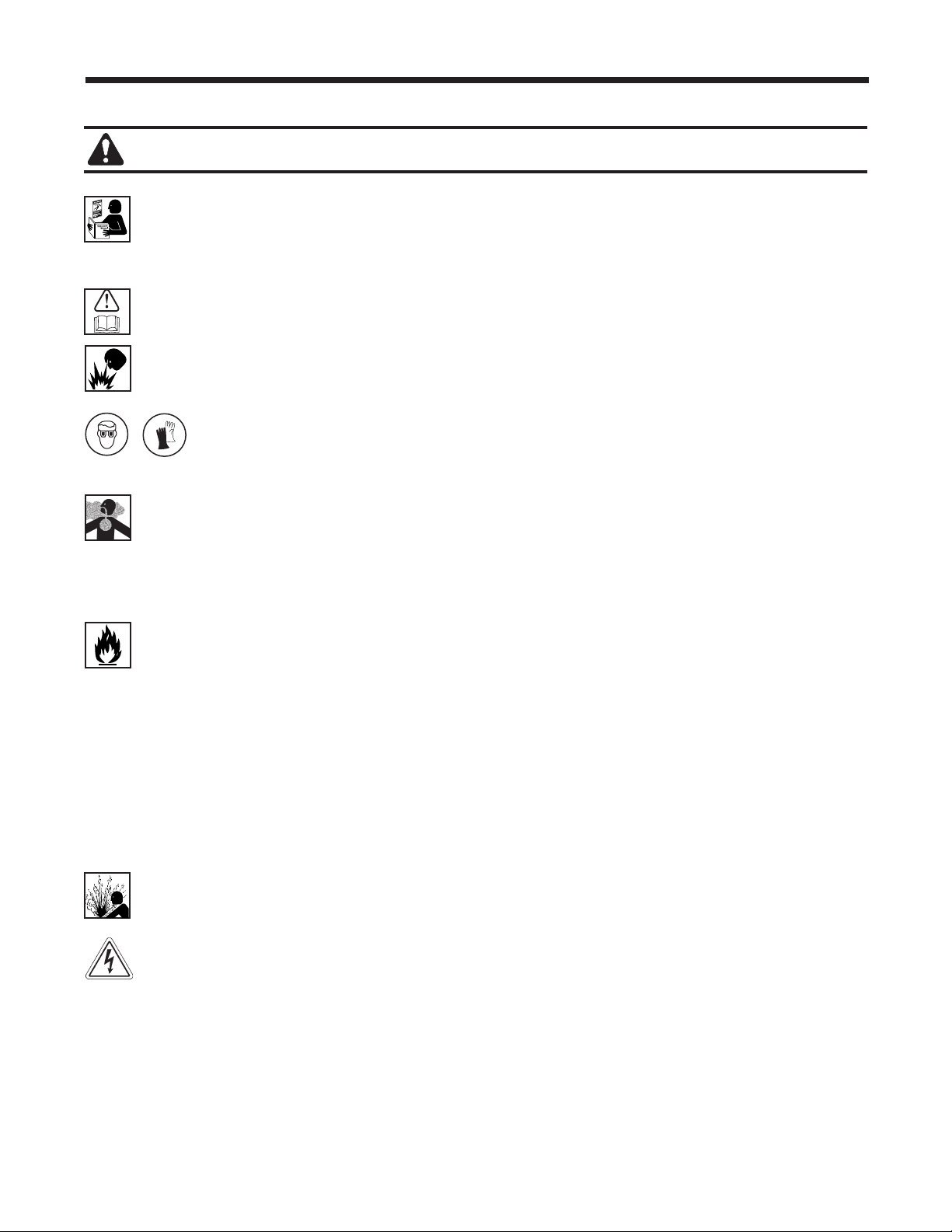
WARNING : To prevent personal injury,
Additional health and safety information may be obtained
from refrigerant and lubricant manufacturers.

4
CAUTION : To prevent equipment damage,
Protective devices
Themachineisequippedwiththefollowingprotectivedevices:
• Overpressurevalves.
• Amaximumpressureswitchstopsthecompressorwhenexcessivepressureissensed.
WARNING: Tampering with these protective devices could result in serious injury.
TO PREVENT CROSS-CONTAMINATION, USE THIS MACHINE WITH R1234YF REFRIGERANT ONLY.
Themachineisequippedwithspecialconnectorstorecover,recycle,andrechargeonlyR1234yfrefrigerant.
Donotattempttoadaptthemachineforanotherrefrigerant.Donotmixrefrigeranttypesthroughasystem
orinthesamecontainer;mixingofrefrigerantswillcauseseveredamagetothemachineandthevehicle
airconditioningsystem.
DO NOT USE THIS MACHINE IN DIRECT SUNLIGHT. Positionthemachinefarfromheatsources,suchas
directsunlight,whichcancauseexcessivetemperatures.Theuseofthismachineundernormalenvironmental
conditions(10°Cto50°C)keepspressuresunderreasonablelimits.
DO NOT USE THIS MACHINE OUTDOORS DURING RAIN OR HIGH HUMIDITY. Protectthemachinefrom
conditionsthatmaycauseelectricalfailureorotherhazardsrelatingtoambientinteraction.
DO NOT USE THIS MACHINE IN AREAS WHERE THERE IS A RISK OF EXPLOSION.
SET UP THE MACHINE ON AN EVEN SURFACE AND UNDER SUFFICIENT LIGHTING. LOCK THE
FRONT WHEELS, AND DO NOT SUBJECT THE MACHINE TO VIBRATION.
Safety Precautions
Additional health and safety information may be obtained
from refrigerant and lubricant manufacturers.
J2843 Requirement Regarding Lubricant
Onlynewlubricant,asspeciedbythesystemmanufacturer,shallbeinstalledintheMAC(MobileAir
Conditioning)system.Lubricantremovedfromthesystemand/ortheequipmentshallbedisposedofin
accordancewithapplicablefederal,state,andlocalproceduresandregulations.
5
AC1234-6 Rev. C
Introduction
ThismachineisdesignedandcertiedtoSAE J2843
HFO-1234yf Recovery / Recycling / Recharging
Equipment for Flammable Refrigerants for Mobile Air-
Conditioning Systems.
Themachineisdesignedtorecoverandrecycle
R1234yfrefrigerant,evacuateairafterthesystemhas
beenopen,andrechargerefrigerant.
Otherfunctionsincludesystemush,diagnostic
pressures,andretentionofservicedatabyvehicleVIN
forrecallandprintout.
Themachineisasingle-passsystem(i.e.refrigerant
owsthroughalteronce)thatmeetsSAEJ2099
specicationsforrecycledrefrigerant.Themachine
alsomeetsoilcross-contaminationrequirementsfor
high-voltagesystemcharge.Followrecommended
serviceproceduresforthecontainmentofR1234yf.
Note: R1234yf systems require special oils. Refer to
the A/C system manufacturer’s service manual for oil
specications.
Technical Specications
Compressor ............................... 1/3HP
Dimensions .................. 107cmx61cmx76cm
Display ........................ 1/4VGAcolorgraphic
Filter Capacity ...............................150kg
Humidity .........90°F(32.2°C),86%RHnon-condensing
Pressure Gauges .........................Ø100mm
Maximum Pressure . . . . . . . . . . . . . . . . . . . . . . . . . . . 25bar
Noise ...................................<70dB(A)
Nominal Voltage ..................103V—127V,60Hz
Oil Drain Bottle ..............................355ml
Operating Temperature .....50°Fto122°F(10°Cto50°C)
Power Consumption ........................ 1100VA
Pump Free-Air Displacement ......... 1.5CFM(35l/m)
Service Hoses ....................250cm/SAEJ2888
Tank Capacity ..................... 9.09kg(20.04lb.)
Weight .............................107kg(235lbs.)
6
Introduction
10
11
12
13
Features of the AC1234-6
9
STOP ESC
OK
HELP MENU
DATABASE
3
2
1
7
8
9
6
4
5

7
AC1234-6 Rev. C
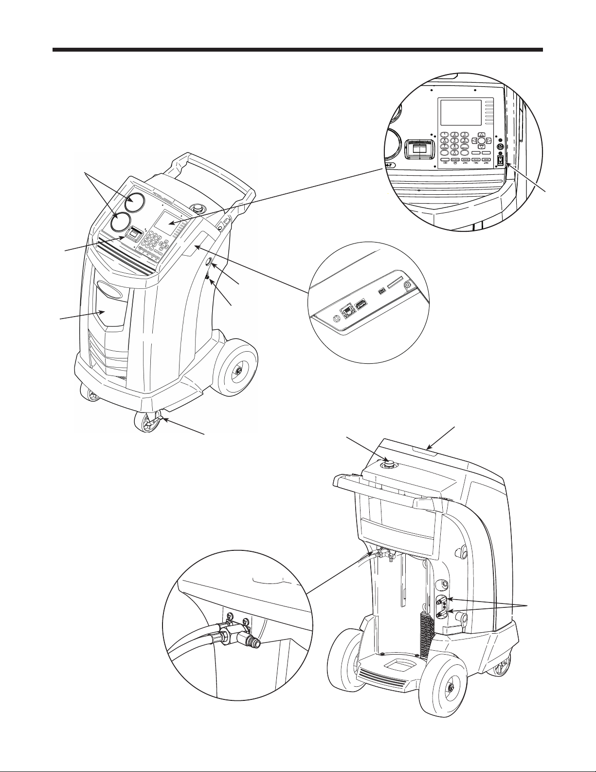
Item
No.
Description
1 OilDrainBottle
2 Printer
3 Low-side(blue)andHigh-side(red)ManifoldGauges
4 GraphicDisplayandKeypad
5 PowerON/OFFSwitch
6 Audio,Ethernet,USB,Mini-USB,andSDCardConnections
7 VacuumPumpOilSightGlass
8 VacuumPumpOilDrainFitting
9 WheelLock
10 VisualAlert
11 VacuumPumpOilFillCapandPort
12 ContaminantRecoveryPort
13 ServiceHoseStoragePorts
Introduction
Features of the AC1234-6 continued
8
9
STOP ESC
OK
HELP MENU
DATABASE
Introduction
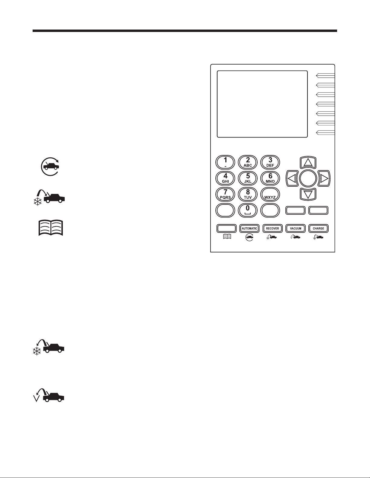
Control Panel Functions
ARROW UP movesselectionofamenuitemtothe
previousitem;turnsupaudiovolume.
ARROW DOWN movesselectionofamenuitemtothe
followingitem;turnsdownaudiovolume.
ARROW RIGHT scrollstonextscreen;fastforwards
thevideo.
ARROW LEFT scrollstopreviousscreen;rewindsthe
video.
AUTOMATIC activatesamenutosetupan
automaticrecovery/vacuum/leaktest/
chargesequence.
CHARGE activatesasequencetocharge
thevehicleA/Csystemwithaprogrammed
amountofrefrigerant.
DATABASE
suppliesinformationregarding
chargecapacitybyvehiclemodel.
ESC returnsthetestsequencetothepreviousscreen;
oranswersaquery.
HELP displaysinformationrelatedtothecurrent
display.
OK highlightsthemenuitem;answersaquery;orstarts
thevideo.
MENU accessesadditionalfunctionsandsetup
parameters.
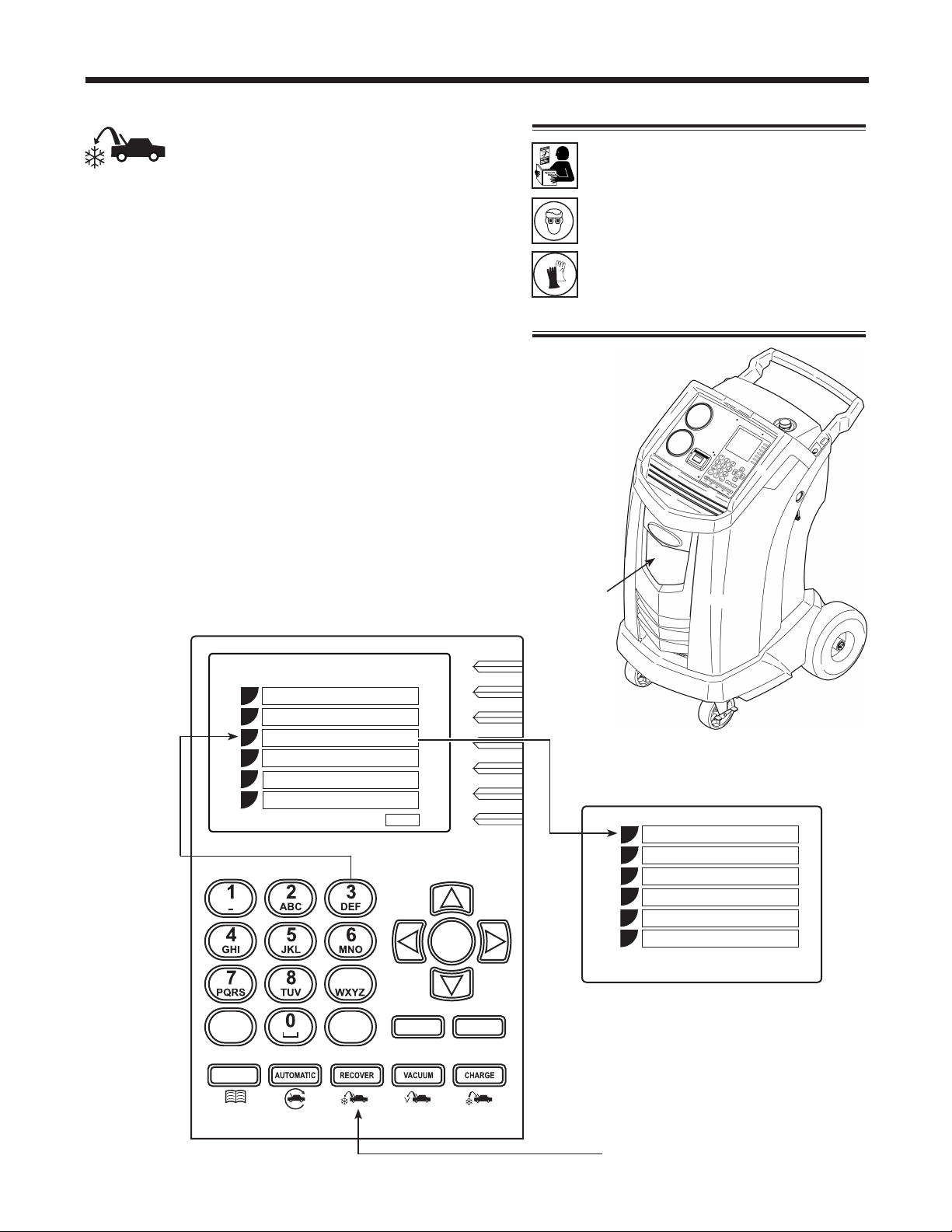
RECOVER activatesasequencetorecover
refrigerantfromthevehicleA/Csystem.
STOP interruptstheactivefunction.Pressonceto
pause,twicetoterminate.
VACUUM activatesasequencetopulla
deepvacuumonthevehicleA/Csystemto
removeairandmoisture.
Control Panel Keypad

9
AC1234-6 Rev. C
Introduction
Air Purge Info
Displaysinternalstoragevessel(ISV)pressure
andtemperature.UsetocheckISVforexcessive
pressure.
Backlight
Adjuststhecontrastonthedisplayscreen.
Beeper Setting
Turnstheaudio“beep”OFFandON.
Calibration Check
Usetoverifyinternalscalecalibration.Referto
Calibration Check intheMaintenancesection.
Change Vacuum Pump Oil
Displayshowlongthevacuumpumphas
operatedsincethelastoilchange,andthe
amountoftimeremaininguntilthenextoil
changeisneeded.Formaximumvacuumpump
performance,changevacuumpumpoilevery
timethelterisreplaced.RefertotheChange
Vacuum Pump Oil intheMaintenancesection.
Date and Time Setup
Programthemachineforcurrentdateandtime.
Default Charge Target
Changethedefaultchargeamountthatappears
onthechargeprogrammingscreen.
Filter Change
Thelterremovesacid,particulates,andmoisture
fromtherefrigerant.Tomeetrequirements,it
ismandatorytoreplacethelterafter150kg
(331lbs.)ofrefrigeranthasbeenltered.
Thismenuitemdisplaystheltercapacity
remaininguntilthemachinelocksdownandno
longerfunctions.RefertoFilter Change inthe
Maintenancesection.
Setup Menu Functions
AccessthefollowingfunctionsbypressingtheMenukeyandselectingSetup.
Garage Data
Programsinformationthatwillappearonthe
printouteachtimetheprintfunctionisused.
Hose Flush
Flushesresidualoilfromthemachinetoprepare
fortheserviceofnextvehicle.
Language Selection
Selectalanguageforscreenprompts.Englishis
thedefaultlanguage.
Refrigerant Management
Displaystheamountofrefrigerantrecovered,
charged,andreplenished(forthelifeofthe
machine),andlteredsincethelastlterchange.
Service
ForRobinairservicecenteruseonly.
System Information
Displaystherevisionlevelofthesoftwareinthe
machine.
Tank Fill Adjustment
Thetankllvaluemaybeadjustedupordown
tosuittheuser’sneeds.Thedefaultis4.5kg
(10lbs.).RefertoTank Fill Adjustment inthe
Maintenancesection.
Tank Filling
Transferrefrigerantfromthesourcetanktothe
ISV.RefertoTank Filling intheMaintenance
section.
Unit of Measure
Programthemachinetodisplayunitsofmeasure
inkilogramsorpounds.Thedefaultdisplayis
kilograms.
10
Setup
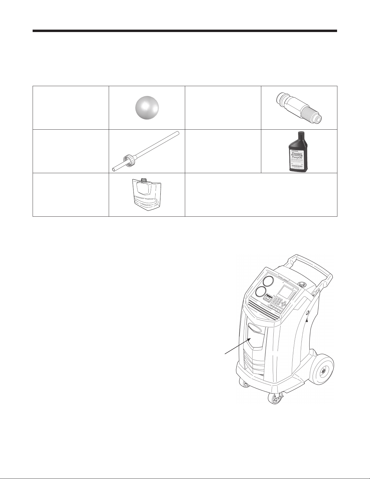
Unpack the Accessory Kit
Unpacktheaccessorykitfromthebox,andremovetheplasticpackaging.
Accessory Kit
Install Oil Drain Bottle
1.Holdtheoildrainbottlestraightandinsertthe
connectorintotheholebehindtheshrouduntilit
snapsintoplace.SeeFigure1.
Oil
Drain
Bottle
Figure 1
CalibrationWeight
533g
TankFillHose
Adapter
CapandFillerTube
VacuumPumpOil
16oz.
OilDrainBottle
Pouchcontainingawarrantycardtobelledout
andmailed,MSDSs,EPAinformation,MACS
information,andaservicecenterlist.
11
AC1234-6 Rev. C
Power Up the Machine
1.Unwindthepowercordfromthehandle,andplugit
intoacorrectvoltage,groundedoutlet.
2.Positionthemachinesotheplugandthemain
powerswitchareofeasyaccessfortheoperator.
Verifythefanventsontherearofthemachineare
notobstructed.
3.Lockthefrontwheels.
4.TurnONthemainpowerswitch.
Setup
CAUTION: The machine is
programmed to run the setup
procedure as outlined here. To prevent
personal injury, do NOT operate the
machine without the oil ll port plug
installed, because the vacuum pump is
pressurized during normal operation.
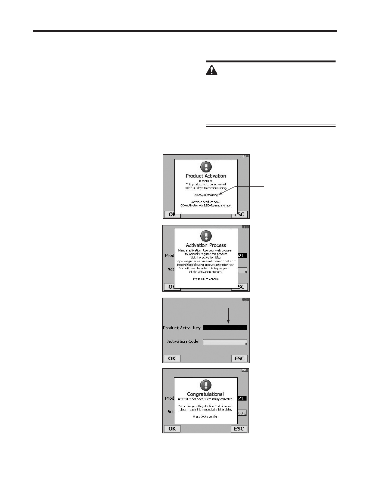
Register the Machine
WhentheProductActivationscreen
appearsonthedisplay,follow
on-screenpromptstoregisterthe
machine.
1.Openawebbrowseronapersonal
computer.Enterthewebaddress
shownintheActivationProcess
screenontheAC1234-6machine.
Enteryourusernameandpassword,
andlogintothewebsite.
Ifyouarearst-timeuser,clickthe
REGISTERbuttontocreateauser
nameandpassword.
2.OntheAC1234-6machine,press
OK.Themachinedisplayseldsfor
theproductactivationkeyandan
activationcode.
3.Entertheproductactivationkeyinto
thecorrecteldonthewebpage.
Thisgeneratesanactivationcode.
4.Entertheactivationcodeintotheeld
ontheAC1234-6displayandpress
OK. Note: Capitalization is required.
5.Recordtheproductactivationkey
andcodeonapieceofpaperandle
itinasecureplace.
6.PressOK.TheAC1234-6hasbeen
activated.
The Product Activation
Key will be displayed in
this eld.
Failure to register and
activate the AC1234-6
within 30 days of initial
startup will cause the
machine to lock out and
no longer function.
12
Figure 2
Service Hoses
Connected to
Storage Ports
Setup
Language Selection
Theoperatorselectsthelanguageforthescreen
promptdisplays.Englishisthedefaultlanguage.
1.UsetheUPorDOWNarrowkeytotogglethrough
theavailablelanguages.
2.PressOKtosettheselectedlanguage.
3.Thelicenseagreementisdisplayedforyour
approval,afterwhichthemachinecontinueswith
SETUP
mode.
Unit of Measure
Theoperatorsetsthedisplayforunitsofmeasure.
Metricisthedefault.
1.UsetheUPorDOWNarrowkeytotoggleMetricor
Englishunits.
2.
PressOK tochoosethedisplayedunitofmeasure.
Date and Time Setup
Themachineisprogrammedatthefactoryforthelocal
timezone,usinga24-hr.clock,anddate.
1.UsetheLEFTandRIGHTarrowkeystomodifythe
minutesdisplayed.
2.UsetheUPandDOWNarrowkeystomodifythe
hourdisplayed.
Note: The date changes only by scrolling through an
entire day.
3.PressOK toacceptthedateandtime.
Service Installation Clearing
Atthispointthemachineclearsitsinternalplumbing
beforeproceedingwithsetup.
1.Whenprompted,connecttheservicehosesfromthe
machinetotheirstorageportsasshowninFigure2.
2.Checkthevacuumpumpoillevelsightglassand
verifytheoilleveliscorrect.
3.Opentheservicecouplers.
Themachineperformsaninternalclearingofits
plumbing,andthensoundsanalarmwhentheTank
FillAdjustmentscreenisdisplayed.
13
AC1234-6 Rev. C
Tank Filling
Theinternalstoragevessel(ISV)maximumllofnew
refrigerantmaybeadjustedbetween1.8kgand6.8kg
byusingthekeypad.Note: The lower the ISV ll level
setting, the greater the ISV capacity for recovery.
Maximum recovery is 9.09 kg.
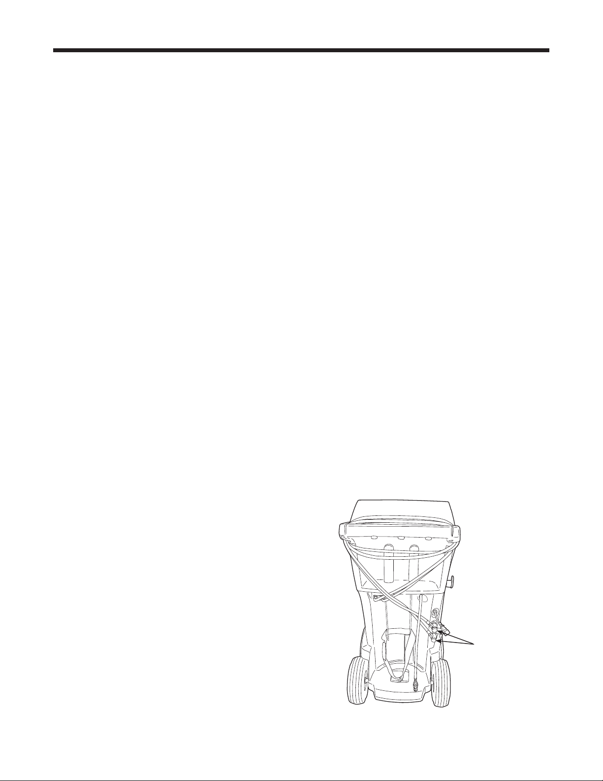
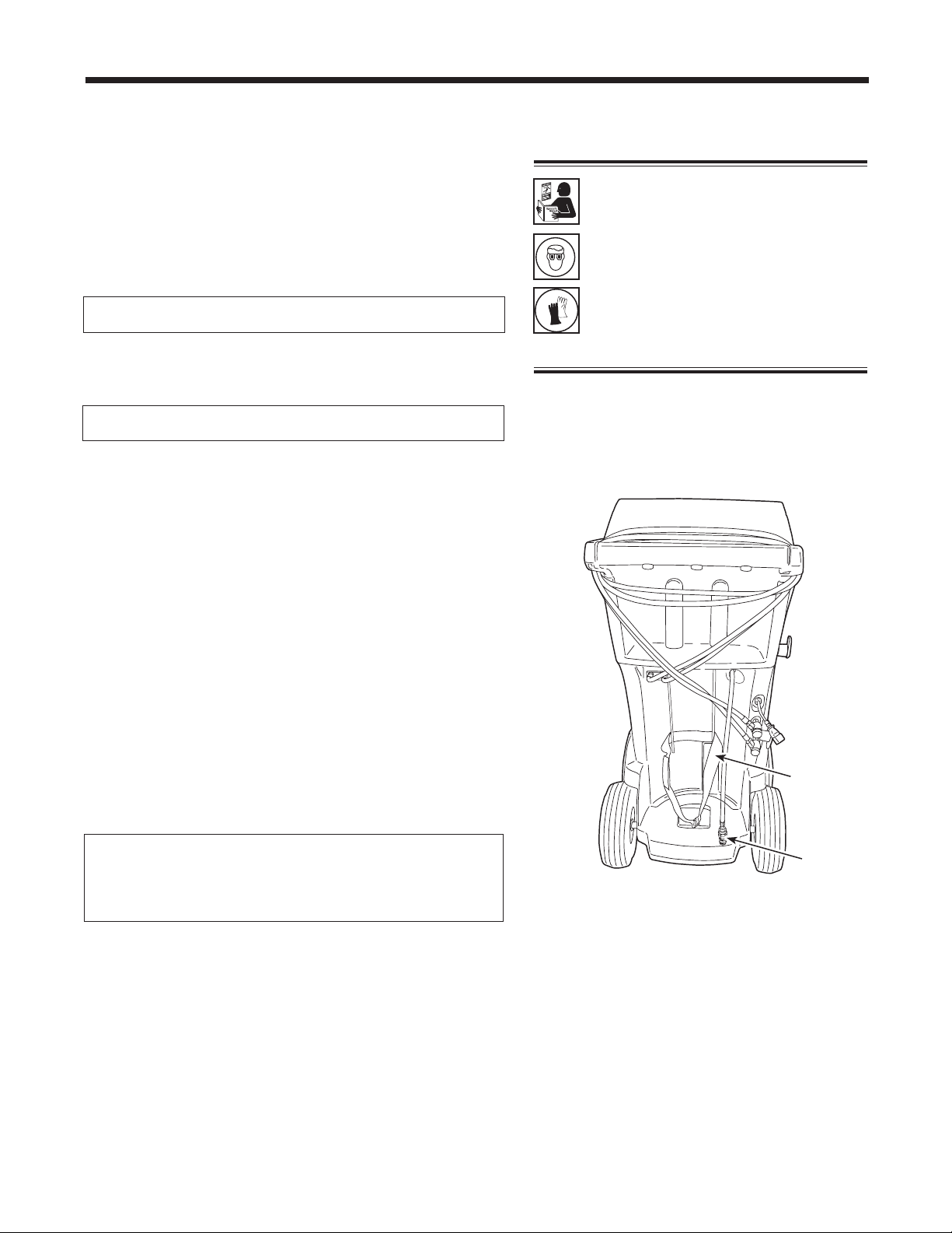
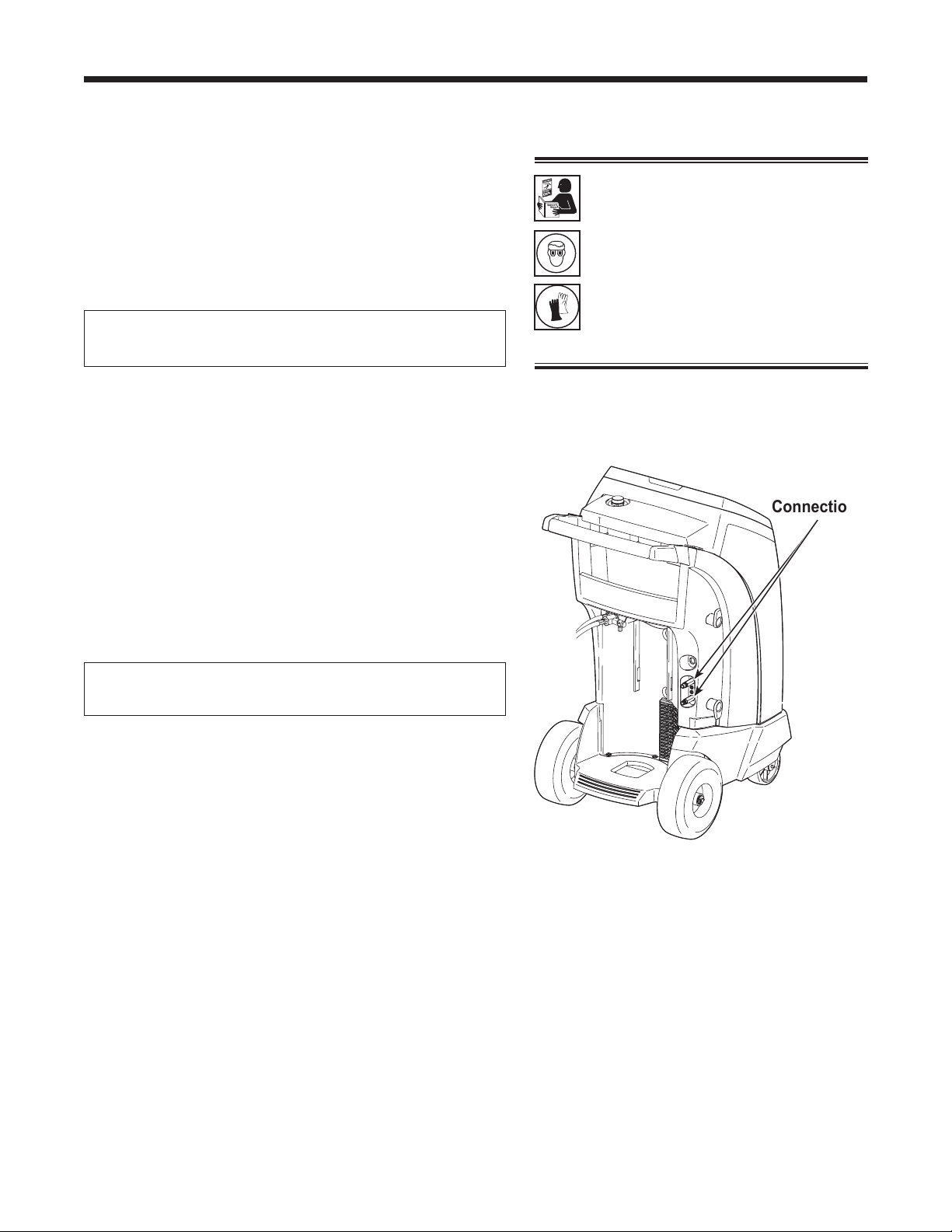
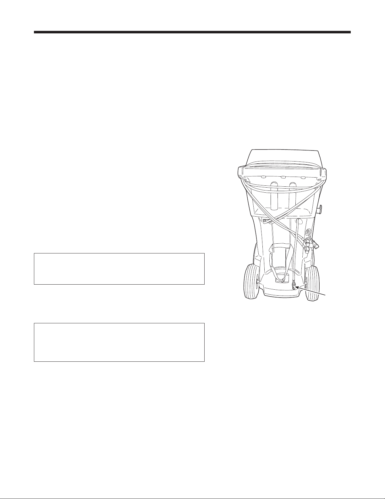
1. Positionthesourcetankontherearofthemachineso
liquidrefrigerantissuppliedtotheconnection.
2. UsethestrapshowninFigure3tosecurethetankin
place,beingcarefultonotblockairowfromthevents
onthelowerrightside.
3. Connectthetankllhosetothesourcetanktting,and
openthetankvalve.
4. PressOK. Themachinecheckstherefrigerantin
thesourcetanktoverifyitisR1234yfanditisnot
contaminated.Themachinedisplays
WARMUP
CALIBRATIONINPROGRESS
GASIDENTIFY
REFRIGERANTPURITYACCEPTABLE
andafterveseconds,beginsllingtheISV.Addatleast
3.6kgofrefrigeranttoensureenoughisavailablefor
charging.Thisprocesstakes15–20minutes.
5. Themachinestopswhenthedesignatedamountof
refrigeranthasbeentransferredtotheISV,orwhen
thesourcetankisempty.Followthemessagesonthe
displayscreen.
6.
PressOKtoreturntotheFunctionsMenu.Themachine
isreadyforoperation.
Note: There is no need to calibrate the scale; it was
calibrated at the factory.
Setup
Note: After the tank ll process is complete,
the display will not show the same amount
as the programmed ll level.
The display shows the amount of refrigerant
that is available for charging, which is
approximately 0.91 kg less than the total
amount of refrigerant in the tank.
WARNING: To prevent personal
injury while working with
refrigerant, read and follow the
instructions and warnings in
this manual, and wear protective
equipment such as goggles and
gloves.
Strap
Tank Fill
Hose
Figure 3
Tank Fill Adjustment
Theoperatormayeitheracceptthemachine’spre-set
defaultweightof4.5kg(10lbs.)ofrefrigerantstoredin
theISV,orchangetoalesseramounttoaccommodate
theapplication.Themaximumamountallowedfornew
refrigerantis6.8kg,whichleavesroomforadditional
recovery.
1. Themachinedisplays
4.5KG
PressOKtoacceptthedefaultamount,orusethe
keypadtoenteranamountandpressOK.
2. Themachinedisplays
CONNECTSOURCETANKTOFILLHOSE
PressOKtocontinueorESCtoexit.
14
Setup
Garage Data
Thismachinehasthecapabilitytoprintoutrecovery,
vacuum,charge,andushinformationforeachvehicle
tested.Theinformationenteredinthelleldsonthe
GarageDatascreenwillappearoneachprintout.
1.PressMENU,selectSetup,andpresstherightarrow
twiceuntilGarageDataappears.
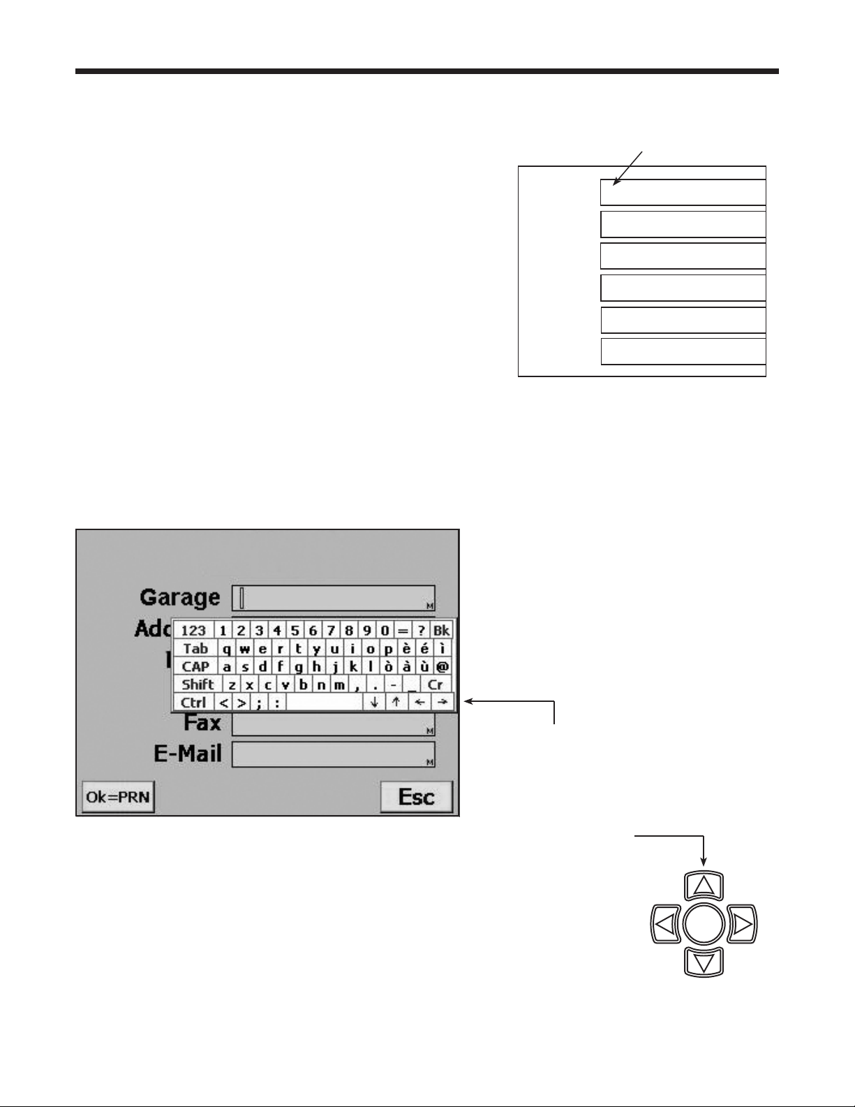
2.Thecursorisblinkingintherstlleld.Referto
Figure4.
3.PresstheMENU keyandavirtualkeyboardappears
asshowninFigure5.
4.Usethearrowkeysonthemachine’skeypadto
movearoundthekeyboard.PressOKtoentera
character.Thecursorwillmovetothenextcharacter.
5.PresstheMENU keytoexitthevirtualkeyboard.
PressOKtosavethedataandmovetothenext
eld.PressESC toreturntotheSetupMenu.
Aprintoutmaybeobtainedanytimethedisplayscreen
showsOK=PRN.
Garage
Address
City
Tel
Fax
E-mail
Figure 4
First Fill Field
Figure 5
Use the arrow
keys in the virtual
keyboard to move
the cursor within
the ll eld.
Use the arrow keys
on the machine’s
keypad to move
around the virtual
keyboard.
9
STOP ESC
OK
HELP MENU
DATABASE

15
AC1234-6 Rev. C
Operating Instructions
VIN Entry
Afterselectinganyservicefunction,informationabout
thevehicleandthevehicleidenticationnumber(VIN)
maybeenteredintothemachine.EnteringtheVIN
activatestheStored Datafeature.
Year
Make
Model
VIN
Entering a VIN when you see this
screen activates the Stored Data
feature.
•
Toskipthisstepandnotstorevehicledata,pressOK.
•
Tostorevehicleservicedata,usethearrowkeysto
selectaeld,usethevirtualkeypadtoenterinformation,
andpressOK.
Stored Data
Themachinestoresservicedataforthelast20VINs
thatwereloggedintotheVINEntryscreen.Complete
serviceresultsmaybeprintedattheendofthe
vehicle’sentireservicebyselectingtheVINfromthe
STORED DATAmenu.
Servicedataincludes
•
VIN
•
vehicleinformation,ifentered
•
ambienttemperatureandhumidity
•
high-sideandlow-sidevehiclediagnosticpressures
•
refrigerantpurity
•
recoveredamount
•
vacuumtime
•
chargedamount
1.TheSTORED DATAmenuisaccessedbypressing
MENUandchoosingFUNCTIONS.
2.ThechoicesunderSTORED DATA are:
•
PRINT DATA RECORD — alistofVINsisdisplayed.
UsetheUPorDOWNarrowtohighlighttheVINfor
whichyouwishtoprintservicedata.
•
DELETE DATA RECORD — followingtheprompts
forthisoptionpermanentlydeletesaVINandany
recordsassociatedwithit.
•
CLEAR ALL DATA — followingthepromptsforthis
optionpermanentlydeletesallVINsandanyrecords
associatedwiththem.
16
Operating Instructions
Diagnostic Pressures
DiagnosticPressuresmodeisusedtocaptureand
printvehiclesystemoperatingpressures.Thefollowing
valuesareavailableforprinting:
•
vehicleinformation
•
systemhigh-sidepressure
•
systemlow-sidepressure
•
ambienttemperatureandhumidity
WhenDiagnosticPressuresmodeisselectedatthe
startofRECOVERYorAUTOMATICrecovery,the
valuesareavailableforprintinguntiltheendofthe
recovery.
Thecaptureofdiagnosticpressuresisrecommendedat
theendofCHARGEorAUTOMATICcharge.
WhenDiagnosticPressuresmodeisselected
fromMENU,valuesmaybeprintedaftercapturing
pressures.Themachinealsorequireshose
equalizationandhoseclear,necessarytoreduce
chargelossduetothediagnosticprocedure.
Printouts
At the End of Every Function
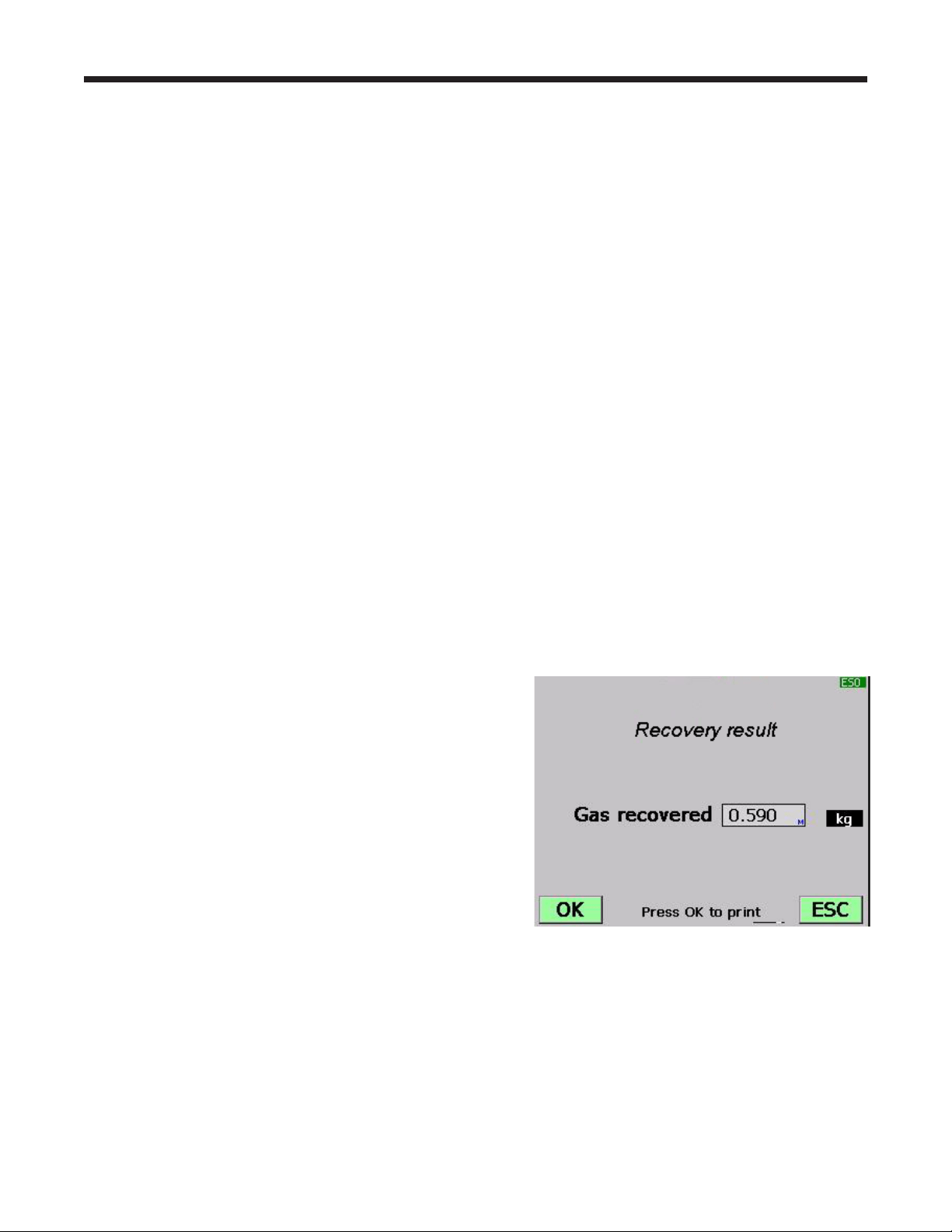
Dataforthefunctionjustcompletedmaybeprinted
fromtheresultsscreenbypressingOKonthe
machine’scontrolpanel.SeeFigure6.
After the Last Complete Service Mode
Asummaryofthecompleteservicemaybeprinted
fromSTORED DATAiftheVINwasenteredintothe
machinewhenprompted:
1.PressMENU onthemachine’scontrolpanel.
2.SelectFUNCTIONS.
3. ThechoicesunderSTORED DATA are:
•
PRINT DATA RECORD — alistofVINsisdisplayed.
UsetheUPorDOWNarrowtohighlighttheVINfor
whichyouwishtoprintservicedata.
•
DELETE DATA RECORD — followingtheprompts
forthisoptionpermanentlydeletesaVINandany
recordsassociatedwithit.
•
CLEAR ALL DATA — followingthepromptsforthis
optionpermanentlydeletesallVINsandanyrecords
associatedwiththem.
Press OK to print data for
the function just completed.
Figure 6
Note:
•
Diagnostic pressures will be available
in Stored Data only when captured with
a VIN entry in Recovery, Automatic, or
Charge modes.
•
Diagnostic pressures captured from
MENU can be printed immediately after
the diagnostic pressures are taken, but
they will not be stored.
•
When running Diagnostic Pressures from
MENU, refrigerant identication occurs
before clearing hoses.
17
AC1234-6 Rev. C
Recover Refrigerant from a Vehicle
1.Emptytheoildrainbottlebeforestartingarecovery.
Removetheoildrainbottlefromthemachineby
pullingthebottlestraightdown—donotusea
twistingorrockingmotion.RefertoFigure7.
2.Connectthehigh-side(red)andlow-side(blue)
hosestothevehicleA/Csystem.
3.Openthecouplervalvesonthehosesbyturningthe
collarsclockwise.
4.SelecttheRECOVERY functionbypressingthe
Recoverbuttononthecontrolpanel,orbyselecting
RecoveryfromtheRRRmenuasshowninFigure8.
5.ThemachinedisplaysaVINentryscreen.Tostore
vehicleservicedatabyVIN,usethearrowkeys
toselectaeld,usethevirtualkeypadtoenter
information,andpressOK.
EnteringaVINisoptional;pressOKtoskipthisstep
andnotactivatetheStoredDatafeature.
Operating Instructions — Recovery
WARNING: To prevent personal
injury while working with
refrigerant, read and follow the
instructions and warnings in
this manual, and wear protective
equipment such as goggles and
gloves.
Oil Drain
Bottle
Press the
number on
the keypad
that
matches
the number
of the
function.
9
STOP ESC
OK
HELP MENU
DATABASE
Setup
Functions
RRR
1
2
3
4
Esc
Another way to select
Recovery is by pressing
the RECOVER button on
the control panel.
Figure 8
Database
Product Activation
Update
Figure 7
Esc
Recovery
Vacuum
Charge
Automatic
1
2
3
4
5
6
System Flush
Diagnostic Pressure
5
6

18
Operating Instructions — Recovery
Recover Refrigerant from a Vehicle continued
6. Themachinedisplays
RUNDIAGNOSTICPRESSURES?
Toprintdiagnosticpressuresatthispoint,followthe
promptstostartthevehicleandsettheA/Csystem
accordingtoservicemanualA/Cperformancetest
requirements.PressOK.
Themachinedisplayswhentocapturethevalues
andwhentheymaybeprinted.
7. Themachinecheckstherefrigerantinthevehicle
toverifyitisR1234yfandnotcontaminated,and
displaysthefollowingscreens:
CALIBRATIONINPROGRESS
GASIDENTIFY
REFRIGERANTPURITYACCEPTABLE
Aftervesecondsthemachinebeginstherecovery
process.Theclickingnoiseindicatesthesolenoidis
openingandclosing—thisisnormal.
8. Themachinerunsaself-clearingcycletoclear
refrigerantfromitsinternalplumbing.
9. Whenthesystemhasrecoveredto0psi,the
vacuumpumpstartsandrunsuntilrecoveryis
complete.
10.Afteroildrainiscomplete,themachinedisplaysa
summaryofgasrecovered. Atthispointyoumay
printoutrecoveryinformationandpre-recovery
diagnosticsbyselectingOK.Thedisplayed
recoveredweightcanvarydependingonambient
conditionsandshouldnotbeusedasanindicator
ofscaleaccuracy.
11.TheamountofoilthatwasremovedfromtheA/C
systemistheamountofnewoilthatshouldbe
chargedintotheA/Csystemafterevacuationis
complete.
•
Useonlynewoiltoreplacetheoilremovedduring
therecyclingprocess.
•
Disposeofusedoilaccordingtogovernment
regulations.
Recoveryiscomplete.
Note: Diagnostic pressures will be available
for printing only until the end of the recovery
function unless a VIN was entered in Step 5.
19
AC1234-6 Rev. C
Evacuate the Vehicle A/C System
1.Connecttheservicehosestothevehicle’sservice
ports.
2.Openthecouplervalvesbyturningthecollars
clockwise.
3.PressVACUUM.
4.ThemachinedisplaysaVINentryscreen.Tostore
vehicleservicedatabyVIN,usethearrowkeys
toselectaeld,usethevirtualkeypadtoenter
information,andpressOK.
EnteringaVINisoptional;pressOKtoskipthisstep
andnotactivatetheStoredDatafeature.
5.
PressOK toacceptthedefaultevacuationtime
(10-minutedefault;5-minuteminimum),orenterthe
desiredvacuumtimeusingthenumberkeys,and
pressOK.
6.ThemachinepullsavacuumontheA/Csystemfor
theprogrammedamountoftime.Duringthevacuum
process,themachinemayperformanairpurge,if
needed.
7.Themachinestopswhenthespeciedamountof
timehaselapsed.Atthispointyoumayprintout
vacuuminformationbyselectingOK.PressESC to
returntothemainmenu.
Operating Instructions — Vacuum
WARNING: To prevent personal
injury while working with
refrigerant, read and follow the
instructions and warnings in
this manual, and wear protective
equipment such as goggles and
gloves.
Note: When the vacuum pump has operated
for 10 hours, the machine prompts for an
oil change. Select OK to proceed with an
oil change; select
ESC
to continue with the
vacuum process. Refer to Change Vacuum
Pump Oil in the Maintenance section of this
manual.
20
Operating Instructions — Hose Flush
WARNING: To prevent personal
injury while working with
refrigerant, read and follow the
instructions and warnings in
this manual, and wear protective
equipment such as goggles and
gloves.
Flushing the Hoses
Ifthemachinewillbeusedtoserviceahigh-voltage
compressorsystem,itisveryimportantthatresidualoil
(suchasPAG)fromthepreviousserviceisushedout
ofthehosesandplumbingbeforebeginningthehigh-
voltageservice.
Atthebeginningofeverychargeprocess,themachine
displays
CHARGINGAHIGHVOLTAGESYSTEM
WITHPOEOIL?
IfOKisselected,themachineguidesyouthroughthe
HoseFlushprocedure.
Note: The Hose Flush procedure may also be selected
from the Setup menu.
1.Connecttheservicehosestothemachine’sstorage
portconnections(showninFigure9).
2.Openthecouplervalvesbyturningthecollars
clockwise.
3.SelectOK tobeginthehoseushprocess,which
runsforthreeminutes,followedbyarecovery.
4.Whenthehoseushingprocessiscomplete,the
displayreads
HOSEFLUSHINGOK
PRESSOKTOCONFIRM
PressOKtoconrmthedisplaymessages.
5.Closethecouplervalvesbyturningthecollars
counterclockwise.
6.PressOK toreturntothepreviousmenu.
Figure 9
Storage
Port
Connections

21
AC1234-6 Rev. C
Recharge the Vehicle A/C System
Thefollowingtestsareautomaticandperformedas
requiredbySAEJ2843:
•
vacuumthatruns5–20minutestoachievethe
correctlevel
•
5-minutevacuumrisetest
•
15%charge
•
manualleaktestusingaleakdetectorcertiedto
SAEJ2913
Notes:
•
J2843 leak testing is intended to nd a gross leak
before charge, for safety reasons. It is not intended
to take the place of other established leak test
practices.
•
The 15% charge is automatically recovered before
recharging the programmed amount.
•
To avoid false failures, the temperatures of the
vehicle system and the recovery machine should be
within ± 5 degrees C.
Refertothevehicleservicemanualforspecicvehicle
instructions.
1.Connectservicehosestothevehicle’sserviceports
andopenthecouplers.
2.PressCHARGE.
3.ThemachinedisplaysaVINentryscreen.Tostore
vehicleservicedatabyVIN,usethearrowkeys
toselectaeld,usethevirtualkeypadtoenter
information,andpressOK.
EnteringaVINisoptional;pressOKtoskipthisstep
andnotactivatetheStoredDatafeature.
4.Themachinedisplays
Operating Instructions — Charge
Usethenumberkeysonthekeypadtomake
selections1–3forthevehicleA/Csystem.For
selection7,enteravalueandpressOK.
WARNING: To prevent personal
injury while working with
refrigerant, read and follow the
instructions and warnings in
this manual, and wear protective
equipment such as goggles and
gloves.
HP
LP
HP + LP
Refrigerant
1
2
3
7
0.590 kg

22
Operating Instructions — Charge
5. Themachinedisplays
CHARGINGAHIGHVOLTAGESYSTEM
THATUSESPOEOIL?
IfOKisselected,themachinepromptsforaHose
Flushprocedure.Connecthigh-side(red)and
low-side(blue)servicehosestothestorageports,
andopenthecouplervalves.PressOK.IfESCis
selected,themachinecontinueswithCHARGE.
6. AfterHoseFlushiscomplete,moveservicehoses
tothevehicle’sserviceportsandopenthecouplers.
PressOK.Themachineperformsautomatictests
onthesystemasrequiredbySAEJ2843.
7. Whenprompted,performamanualleaktestusinga
leakdetectorcertiedtoSAEJ2913.Oncetheleak
testhasbeencompleted,CHARGEcontinues.
Movingorbumpingthemachineatthispointmay
resultinaninaccuratecharge.Whenthecharge
cyclegetsclosetothedesiredweightvalue,the
machineslowsdown.Itwillcharge,settle,charge
again,settle,etc.
8. AttheendofCHARGE,themachineprompts
throughaDiagnosticPressurestest.
9. Followpromptstoequalizeliquidrefrigerantintothe
vehicleA/Csystemformaximumchargeaccuracy.
10.Whenprompted,closethecouplervalvesand
removetheservicehosesfromtheA/Csystem.
Installthehosesonmachine’sstorageports.
11.PressOKtobeginclearinghosestopreparethe
machineforthenextservice.
12.Whenthehosesareclear,thedisplayshowsa
summaryofchargeresults,whichmaybeprinted
bypressingOK.
Note: If a VIN was entered when prompted,
complete service results may be printed at the
end of the vehicle’s entire service by selecting the
vehicle VIN from the STORED DATA menu.
The STORED DATA menu is found by pressing
MENU and choosing FUNCTIONS.
ThevehicleA/Csystemisnowreadyforuse.
Charge continued
CAUTION: If the low-side (blue) or high-
side (red) coupler valve is left open
during the hose clearing process, the
system will pull refrigerant back out of
the vehicle.
Note: The charge process includes an
automatic vacuum leak test, after which the
system is pressurized with a small amount
of refrigerant for a manual leak test.
•
If the leak test passes, the refrigerant is
automatically recovered and the selected
charge is added.
•
If the leak test fails, the refrigerant needs
to be recovered and the vehicle needs
to be checked for leaks by using an
electronic leak detector.
23
AC1234-6 Rev. C
Operating Instructions — Automatic
WARNING: To prevent personal
injury while working with
refrigerant, read and follow the
instructions and warnings in
this manual, and wear protective
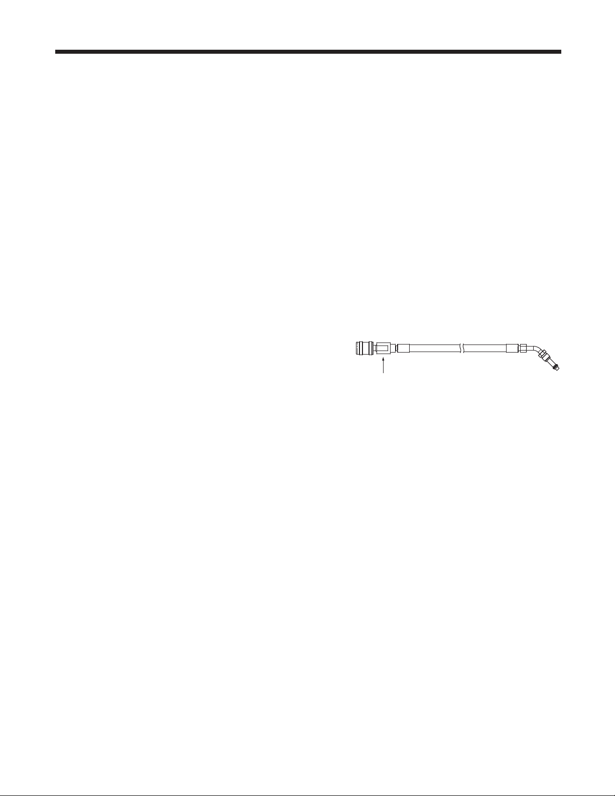
equipment such as goggles and
gloves.
Automatic Function
The AUTOMATICfunctionallowsausertoprograman
automaticrecovery,vacuum,leaktest,and/orcharge
sequence.Theusermaychoosetoskipanystepinthe
automaticoperationduringtheprogramming.Atotal
automaticsequencemaytakeuptoanhour.
Usethenumberkeysonthekeypadtomake
selections1–3forthevehicleA/Csystem.For
selections5–6,acceptthedefaultvalues,orenter
valuesandpressOK.
5.
If no pressure is detected,themachineproceedsto
thenextprogrammedmode(VACUUMorCHARGE).
If pressure is detected,themachinepromptsto
rundiagnosticpressuresbeforerecovery:
RUNDIAGNOSTICPRESSURES?
RunningdiagnosticpressuresbeforeRECOVERY is
optional;diagnosticpressuresshouldberunwhen
promptedafterCHARGE.
PressOKtorundiagnosticpressures;pressESCto
continuewithRECOVERY.
1.Connectservicehosestothevehicle’sserviceports
andopenthecouplers.
2.PressAUTOMATIC.
3.ThemachinedisplaysaVINentryscreen.Tostore
vehicleservicedatabyVIN,usethearrowkeys
toselectaeld,usethevirtualkeypadtoenter
information,andpressOK.
EnteringaVINisoptional;pressOKtoskipthisstep
andnotactivatetheStoredDatafeature.
4.Themachinedisplays
HP
LP
HP + LP
Refrigerant
Vacuum
1
2
3
5
6
0.590 kg
10 min.
Note: If problems are encountered during
the automatic sequence, the machine
will “beep” three times, the red lights on
the front of the machine will blink, and
the control panel readout will pinpoint
the problem encountered. The sequence
remains paused until the user enters a
decision regarding how to proceed.

24
Operating Instructions — Automatic
6.IfOKwasselected,followpromptstostartthe
vehicleandsettheA/Csystemaccordingtoservice
manualA/Cperformancetestrequirements.Press
OKafterpressurestabilizes.PressOKagaintoprint
data;pressESCtocontinuewithRECOVERY.
7. Themachinecheckstherefrigerantinthevehicleto
verifyitisR1234yfandnotcontaminated,whichis
requiredbySAEJ2843.Themachinedisplaysthe
followingscreens:
WARMUP
CALIBRATIONINPROGRESS
GASIDENTIFY
REFRIGERANTPURITYACCEPTABLE
Ifthepurityreadingisacceptable,themachine
performsarecovery,andsystemoilisdrained
attheend.Ifvacuumtimewasprogrammed,the
machineperformsavacuum.
8. IfCHARGEwasselected,themachinedisplays
CHARGINGAHIGHVOLTAGESYSTEM
THATUSESPOEOIL?
IfESCisselected,themachinecontinueswith
CHARGE.IfOKisselected,themachineprompts
forahoseushprocedure.Connecthigh-side(red)
andlow-side(blue)servicehosestostorageports
onthemachine.Opencouplervalves.PressOK.
9. Reconnectservicehosestothevehicle’sA/C
system.Opencouplervalves.PressOK. The
machineperformsautomatictestsonthesystemas
requiredbySAEJ2843.
10.Whenprompted,performamanualleaktestusinga
leakdetectorcertiedtoSAEJ2913.Oncetheleak
testhasbeencompleted,CHARGEcontinues.
11.AttheendofCHARGE,themachineprompts
throughaDiagnosticPressurestest.
12.Followpromptstoequalizeliquidrefrigerantintothe
vehicleA/Csystemformaximumchargeaccuracy.
13.Whenthesequenceiscomplete,closethehigh-
side(red)andlow-side(blue)couplervalves.
14.Whenprompted,removeservicehosesfromthe
A/Csystemandinstallthemonthemachine’s
storageports.SelectOKtobeginclearinghoses.
Thispreparesthemachineforthenextservice.
15.Themachinedisplaysasummaryofactions
performedduringtheautomaticsequence.
Automatic continued
CAUTION: If the low-side (blue) or high-
side (red) coupler valve is left open
during the hose clearing process, the
system will pull refrigerant back out of
the vehicle.
Note: Diagnostic pressures will be
available for printing only until the end of
the Automatic function unless a VIN was
entered in Step 3.
25
AC1234-6 Rev. C
Operating Instructions — System Flush
System Flushing Process
Thismachineprovidesamethodofremovingoilby
forcingliquidrefrigerantthroughanA/Csystem,or
componentsofanA/Csystem.Aspecialushing
adapter(purchasedseparately)accessestheA/C
systematthecompressorblock.Afterushing,the
refrigerantisrecoveredbythemachineandlteredby
therecyclingcircuit,returningittoSAEpuritylevels.
A/Csystemsvaryandmayrequiretheadaptingand
ushingofindividualcomponents.Refertoservice
bulletinsasneededduringthisprocedure.
Notes:
•
The machine must have at least 4.5 kg (10 lbs.) of
refrigerant available in the ISV (as indicated on the
display) for charging.
•
If the ush process is interrupted by an accidental
power-down or other fault, use the Recovery mode
to remove the refrigerant from the vehicle.
Setup
1.Verifytheoildrainbottleonthefrontofthemachine
isempty.SeeFigure10.Recoverrefrigerantas
outlinedinthismanualunderRecover Refrigerant
from a Vehicle.
2.Closeservicecouplervalvesanddisconnecthoses
fromvehicleaccessports.
3.Closethevalveontheexternalsourcetank.
Note: During this procedure, up to
4.5 kg (10 lbs.)
of refrigerant is charged into the vehicle A/C system.
If the ushing cycle is stopped before it is complete
and the external source valve is open, the machine
automatically adds refrigerant to the ISV, and there will
be no room to recover the refrigerant used for ushing.
4.RemovetheA/Csystemexpansiondevice,and
reconnectthettingstocreateabypass.
5.Disconnectthecompressorblockattherearofthe
compressor.
6.Attachthecompressorblockadapter(fromthe
ushingkit)tothesystemsideofthecompressor
block.
Figure 10
Oil Drain
Bottle
WARNING: To prevent personal
injury while working with
refrigerant, read and follow the
instructions and warnings in
this manual, and wear protective
equipment such as goggles and
gloves.
26
Operating Instructions — System Flush
WARNING: Do NOT disconnect
service couplers during the ushing
process. Refrigerant could spray out of
the ttings, and exposure may cause
personal injury.
7.Conguretheblockconnectorstoprovideforward-
orback-ushingoftherefrigerant,whichowsfrom
themachinethroughtheredhigh-sideconnection
hose.Opentheredservicecoupler.
8.Connectthelterhousingtothedesiredreturnside
oftheadapterblockandtothebluelow-sidehose.
Opentheblueservicecoupler.
9.Verifythataushinglteriscorrectlyinstalledinthe
ushinglterhousing.Opentheisolationvalveon
thehose.
Operating Instructions
1.SelectSYSTEM FLUSHfromtheRRRmenu.See
Figure11.
2.ThemachinedisplaysaVINentryscreen.Tostore
vehicleservicedatabyVIN,usethearrowkeys
toselectaeld,usethevirtualkeypadtoenter
information,andpressOK.
EnteringaVINisoptional;pressOKtoskipthisstep
andnotactivatetheStoredDatafeature.
3.SelectSTART toacceptthedefaultushtimeof10
minutes,orenterthedesiredushtimeusingthe
keypadandselectSTART.
4.Thevacuumpumprunsforveminutestoremove
airfromtheA/Csystem,ifneeded.
5.
Themachineushesthesystemforthedesignated
lengthoftime,andthenentersarecoverymode.
6.
Oilthathasbeencollecteddrainsintothegraduated
oildrainbottle.Removethebottleandmeasureoil.
Disposeofoilaccordingtothelawsinyour
jurisdiction.Itistheresponsibilityoftheuserto
determineifamaterialisahazardouswasteatthe
timeofdisposal.
7.
WhenthemachinedisplaysFLUSHCOMPLETE,close
servicecouplers,removehoses,andreassemblethe
vehicle’sA/Csystemtoitsoriginalstate.
8.Openthevalveonthesourcetank.
9.Evacuateandrechargethevehicleaccordingtothe
instructionsinthismanual.
Operating Tips
If the external ushing lter is plugged, the
unit displays
SYSTEMFLUSH
POSSIBLECLOGGEDFLUSHFILTER
ORCLOSEDCOUPLERVALVE
ESCTORECOVERREFRIGERANT
PRESSOKTORETRY
After the lter is cleared or replaced, restart
System Flush from the menu shown in
Figure 11.
CAUTION: To prevent vehicle damage, use an
oil inject tool to replace the system oil. Flushing
removes all oil from the system except what
remains in the compressor.
1
2
3
4
5
Recovery
Vacuum
Charge
Automatic
Esc
Figure 11
The RRR Menu
Diagnostic Pressures
6
System Flush
È
27
AC1234-6 Rev. C
Maintenance
WARNING: To prevent personal
injury,
•
Only qualied personnel may
perform inspections and
repairs to this machine.
•
Read and follow the
instructions and warnings
in this manual, and wear
protective equipment such as
goggles and gloves.
•
Do not operate the machine
when the shroud has been
removed.
General Maintenance
Wipeoffthemachineoftenusingacleanclothto
removegreaseanddirt.
Periodicallycheckhosesandconnectionsforleakage.
UseaJ2913electronicleakdetectortocheckttings
whentheunithasbeendisconnectedfromitspower
sourceandtheshroudhasbeenremoved.Ifyou
detectaleakthatyoucan’trepair,contactaRobinair
authorizedservicecenter.
Electrical Protection
Themachineisequippedwithafuselocatedinside
thefrontshroud.Trytodeterminethecauseofthe
fusefailure,suchasanincorrectpowersourceoran
extensioncordthatistoolong.
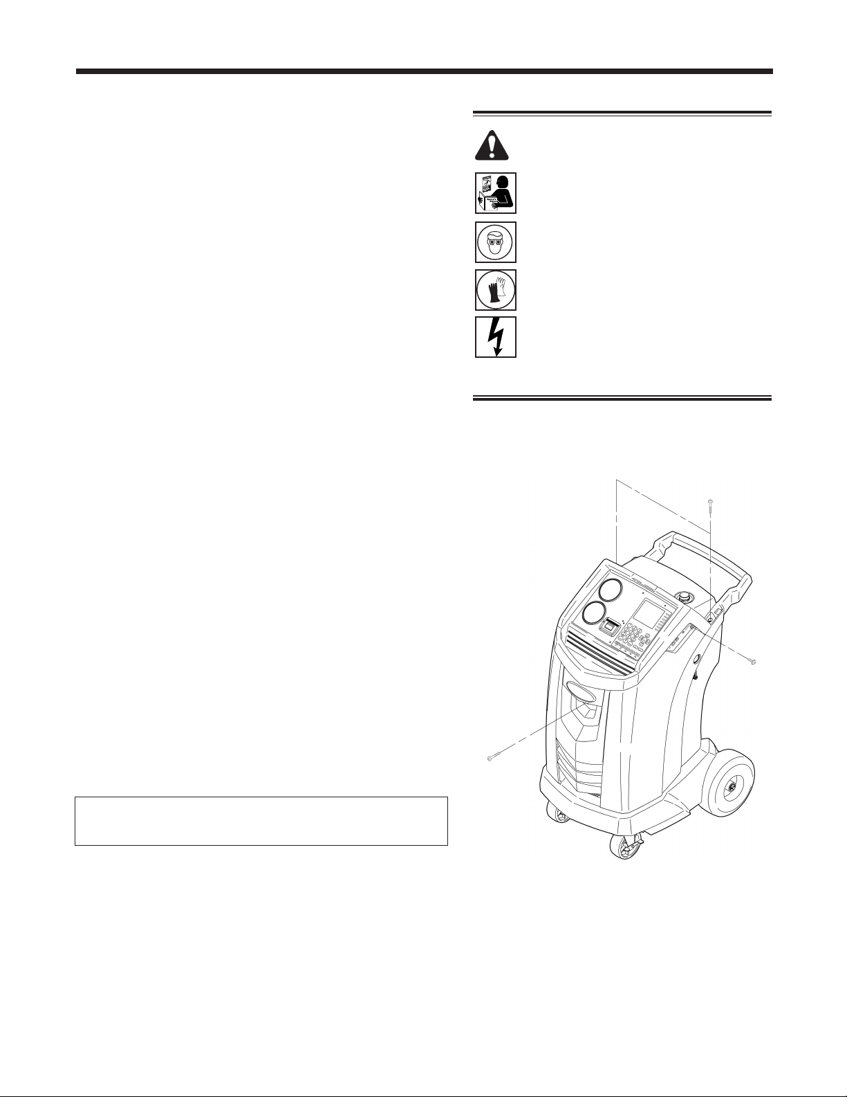
1.Disconnectthemachinefromitspowersource.
2.Removetheoildrainbottle.
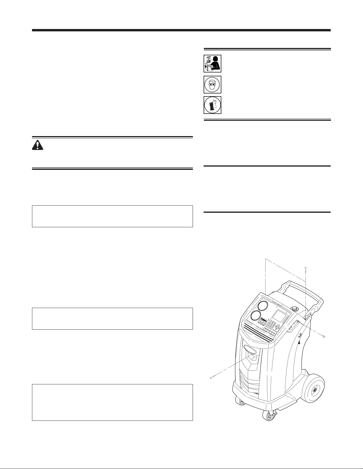
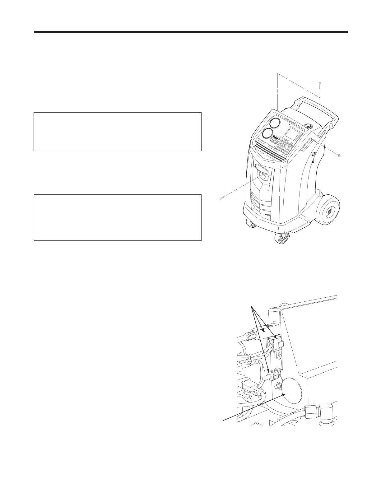
3.RemovethefourscrewsshowninFigure12,and
removetheshroud.
4.Locatethefuseonthecentersheetmetal.Replace
thefusewiththesameamperageandtype.
5.Replacetheshroudandtheoilbottle.
Tank Fill Adjustment
Themaximumsettingfortankllis6.8kg(15lbs.).
Thisvaluemaybeadjustedtosuittheapplication.The
minimumvalueis1.8kg(4lbs.).
1.SelectTANK FILL ADJUSTMENTfromtheSetup
menu.
2.Themachinedisplaysthedefaultamountof
refrigerant:
TANKLEVEL
4.5KG
3.SelectOKtoacceptthedefaultamount,orusethe
keypadtoenteranamountandselectOK.
Figure 12
Remove the four screws
holding the shroud.
28
Maintenance
Tank Filling
Thismenuitemisusedtotransferrefrigerantfroma
sourcetanktotheISV.Thisprocedureworksonlyif
theISVcontainslessthanthemaximumamountof
refrigerantprogrammedunderTankFillAdjustment.
(Seepreviouspage.)
Note: If a source tank is connected to the tank ll
hose while the machine is sitting idle, the machine
automatically adds refrigerant up to the level set during
Tank Fill Adjustment.
1.ConnectanR1234yfsourcetanktothetankllhose
attherearofthemachine.Note: The tank ll hose
and the tank access port have left-hand threads.
Handtightenthetankllhose.
2.Openthetankvalve.
3.Mountthesourcetankontheshelfattherearofthe
machine,orientedtosupplyliquidrefrigeranttothe
connection.Tightentheholdingstraparoundthe
sourcetank. Verifythetankdoesnotrestrictairow
fromthevent.
4.SelectTANK FILLINGfromtheFunctionsmenu.
Themachinedisplays
FILLAMOUNT
XX.XXX
CONNECTSOURCETANKTOFILLHOSE
5.PressOK.Themachinecheckstherefrigerant
inthesourcetanktoverifyitisR1234yfandnot
contaminated.Themachinedisplaysthefollowing
screens:
WARMUP
CALIBRATIONINPROGRESS
GASIDENTIFY
REFRIGERANTPURITYACCEPTABLE
andaftervesecondsbeginsllingtheinternal
storagevessel(ISV).
6.Themachineautomaticallystopswhenthepreset
tanklllevelisreached.Tostopthetankllbefore
thepresetlevelisreached,selectESC.
7.Ifusinganon-rellabletank,themachinemust
displaySOURCETANKEMPTYbeforethetankmay
bediscarded.
Tank Fill
Hose
Figure 13
29
AC1234-6 Rev. C
Maintenance
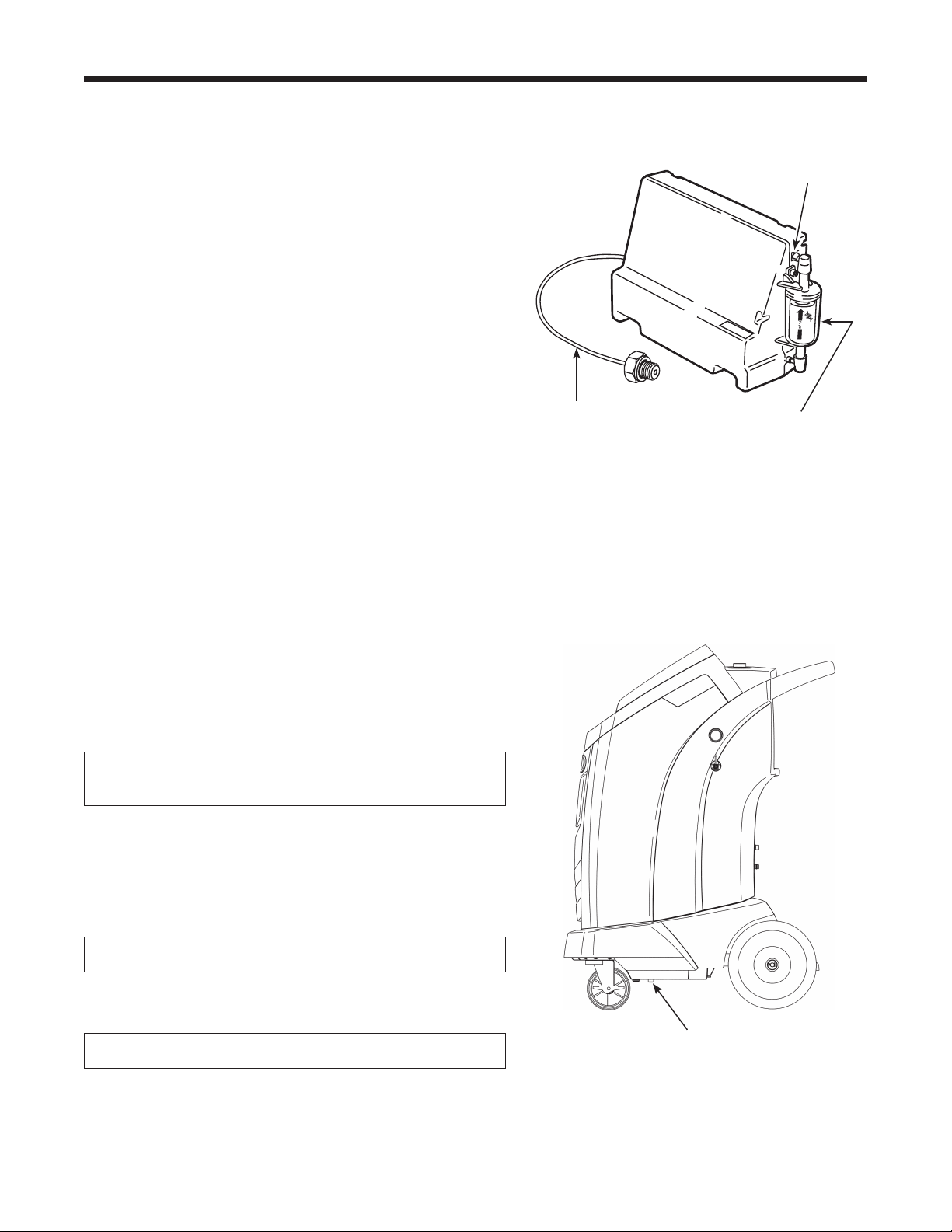
Tank Fill Hose Filter Service
Thetankllhoseattherearofthemachine(see
Figure13)containsalterthatcanbecleanedwhenit
appearsthatrefrigerantowisrestricted.
Whenthemachinesenseslowow,itmaydisplayone
ofthefollowingmessages:
•
SOURCETANKEMPTY,butyetyouknowthe
sourcetankcontainsrefrigerant,connectionsare
secure,andthesourcetankvalveisopen.
•
REPLACEIDENTIFIERFILTER,butyetyouknow
therefrigerantidentierlterisnotrestricted,the
sourcetankcontainsrefrigerant,connectionsare
secure,andthesourcetankvalveisopen.
Thecausemaybethatthetankllhoselteris
plugged.
Cleaning the Tank Fill Hose Filter
1. Firstensurethatpressuredoesnotexistinthe
line.Disconnecttheexternalsourcetank,and
performamanualtanklltocaptureanyrefrigerant
intheline.
2. Disassemblethetankllhoseatthelterhousing
asshowninFigure14.
3. Removeandcleanthelter.
4. Afterthelterhasbeeninstalledbackintothelter
housing,torquethehousingassemblyto8.5N•m
(6ft.lbs.).
Disassemble the
Filter Housing
Figure 14
Disassemble the
Filter Housing
30
Maintenance
Caution: To prevent equipment damage,
use only authentic Robinair No. 34724
lters in this machine. All performance
tests and claims are based on using this
specic lter.
WARNING: To prevent personal
injury while working with
refrigerant, read and follow the
instructions and warnings in
this manual, and wear protective
equipment such as goggles and
gloves.
Filter Change
Thelterisdesignedtotrapacidandparticulates,
andtoremovemoisturefromrefrigerant.Tomeet
themandateforadequatemoistureandcontaminant
removal,theltermustbereplacedafter150kg
(331lbs.)ofrefrigeranthasbeenltered.
Themachinegivesawarningwhen100kg(220lbs.)
oftheltercapacityhasbeenused;themachinelocks
downwhenthe150kg(331lb.)ltercapacityhasbeen
reachedandwillnolongerfunction.
WARNING: The components in the machine are
under high pressure. To prevent personal injury,
change
the lter only when the machine prompts.
Check Remaining Filter Capacity
1.SelectFILTER CHANGEfromtheSetupMenuor
whenthemachineprompts.Themachinedisplays
FILTERLIFETIME:X.XXKG
REPLACEFILTER?
Themachinedisplaystheamountofltercapacity
remaininguntilthemachinelocksdown.
2.Whenprompted,selectOKtochangethelter;
selectESC toresumeusingthemachine.
Replace the Filters and Sample Hose Assembly
1.IfOK wasselectedtochangethelter,themachine
clearsthelter,thenpromptsforthenewltercode
tobeentered.
WAITINGFORFILTERTOBECLEARED
SERIALNR.FILTER
Usethekeypadtoentertheserialnumberthat
appearsonthenewlterandselectOK.IfSERIAL
NUMBERWRONGisdisplayed,theserialnumber
hasbeenincorrectlyentered,orthelterhasalready
beenusedinthismachine.
2.Themachinedisplays
TURNUNITOFF
REMOVESHROUDANDREPLACEFILTER,
IDENTIFIERFILTER,AND
IDENTIFIERSAMPLEHOSE
Shutoffthemachine.Removetheoilbottle.Remove
thefourscrewsholdingtheshroud.SeeFigure15.
Figure 15
Remove the four screws
holding the shroud.
31
AC1234-6 Rev. C
Maintenance
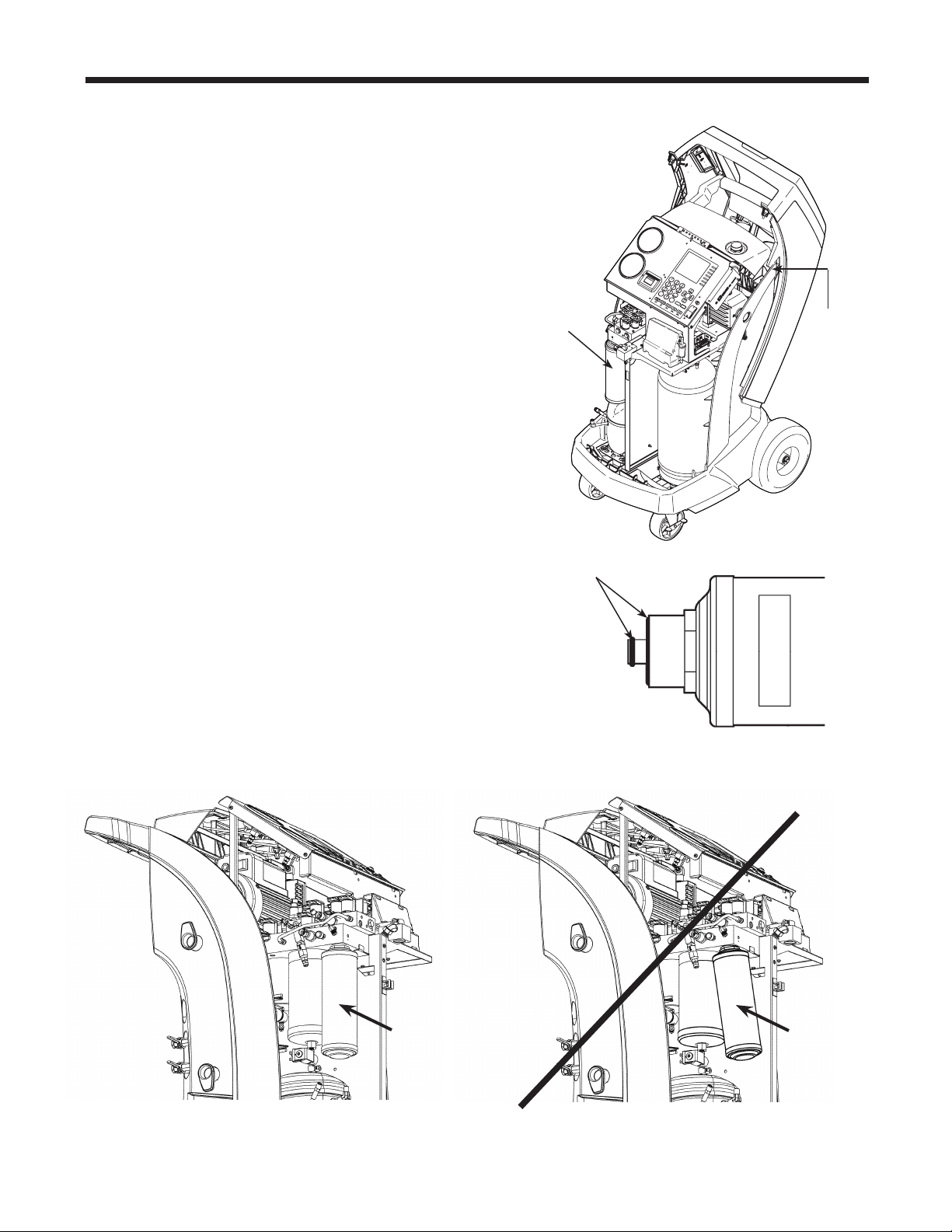
3.Hangtheshroudonthebackofthemachineas
showninFigure16.
4.Removethelterbyturningitcounterclockwise(as
viewedfromthebottomofthelter).
5.Lookatthenewlter—verifybotho-ringsare
lubricatedandcorrectlylocatedinthegroovesas
showninFigure17.
6.Installthenewlterbythreadingitclockwiseinto
place.Verifythelterispositionedcorrectlyas
showninFigure18.Tightenthelterto20N•m.
Filter Change continues on next page
Filter Change continued
O-rings
Figure 17
9
S
T
OP
E
S
C
O
K
H
E
L
P ME
N
U
Figure 16
Filter
Hang
Shroud
Here
Figure 18
Assembled
Correctly
Assembled
Incorrectly
32
Maintenance
Refrigerant Identier
Therefrigerantidentiersamplesrefrigerantgoing
intotheISVtoverifyitisR1234yfandthatitisnot
contaminated.Replacethesamplehoseassembly
duringeverylterchangeandalsoifpromptedby
anerrormessagesayingthehoseisclogged.See
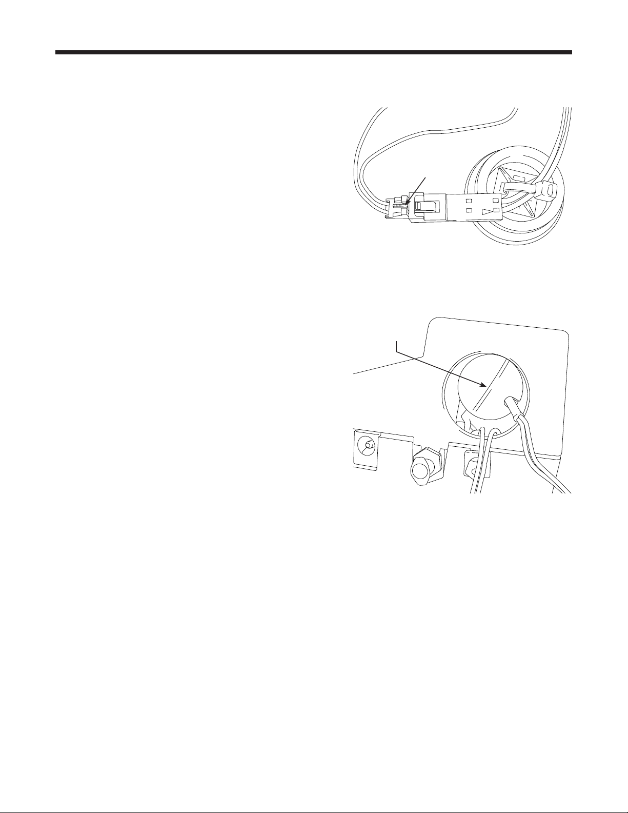
Figure19.
7. Disconnecttheexistingsamplehoseassembly
betweenthesolenoidandtherefrigerantidentier,
andinstallanewsamplehoseassembly.
Note: If the lter is any color but white, the lter
needs to be replaced.
8. Pullthelteroutofthebracketswhileremovingthe
barbsfromtherubberconnectors.
9. Installanewlterwiththearrowpointingupward
asshown.Pushthelterbarbsintotherubber
connectors.
10.Installtheshroudonthemachineandswitchthe
powerON.
Magnet
Figure 20
Calibration Check
Thisfunctionisusedtoensurethemachine’sinternal
scaleisalwayscalibrated.Duringthistest,useonlythe
calibrationweightthatisprovidedwiththemachine.
1.SelectCALIBRATION CHECKintheSetupmenu.
Themachinedisplays
PLACESAMPLEWEIGHTONSCALE
PRESSOKTOTESTPRESSESCTOQUIT
2.RefertoFigure20,andverifythemagnetonthe
bottomofthemachineisclean.
3.Attachthecalibrationweighttothemagnetonthe
bottomofthemachine.SelectOK.
•
Ifthedisplayshows
PROCEDURECOMPLETED
thescaleisincalibration.SelectOK.
•
Ifthedisplayshows
CALIBRATIONREJECTED!
thescaleisoutofcalibration.Contactanauthorized
Robinairservicecenterforassistance.
4.Removethecalibrationweightfromthescale.
Refrigerant Identier
Install new lter with
arrow
↑
positioned as
shown.
Barb
Figure 19
Replace the sample hose assembly
during every lter change.
Sample Hose
Assembly
33
AC1234-6 Rev. C
Maintenance
Replace the Oxygen Sensor in the Refrigerant Identier
Figure 21
Remove four screws
holding shroud.
Therefrigerantidentierinthemachinecontainsa
replaceableoxygensensorthatmayaffectthewaythe
machineworksifthesensorisnotfunctioningcorrectly.
•
Ifthemachinedisplaysthefollowingmessage,
immediatelyreplacetheoxygensensor:
OPERATINGTIMEOFTHEIDENTIFIERANDUNIT
ARELIMITED
REPLACEIDO2SENSORSOON
UNITWILLBECOMENONFUNCTIONAL
•
Ifthemachinedisplaysthefollowingmessage,the
oxygensensorhasexpired.Neithertheidentiernor
themachineisabletorecoveroraddrefrigerantto
theinternaltank.
ANALYZERERROR6
O2SENSORFAILURE
SENSORMUSTBEREPLACED
UNITWILLNOTRECOVERORALLOWTANKFILL
SEEMANUAL
Replace the Oxygen Sensor
1.Disconnectthemachinefromitspowersource.
2.Removetheoilbottle,andremovethefourscrews
holdingtheshroud.SeeFigure21.Hangtheshroud
onthebackofthemachine.
3.Disconnectthewireharness,USBconnector,and
samplehosefromtheidentier.SeeFigure22.
4.Removethetwoscrewsholdingtheidentiertothe
machine,andremovetheidentier.
5.Carefullyprytheoxygensensorcapfromthe
housing.Gentlypullonthecapandwiresuntilthe
connectorexitsthehousing.
CAUTION: The wire connected to the cap is
connected internally to the identier. To prevent
equipment damage, do NOT pull on this wire.
Disconnect wire harness,
USB connector,
and sample hose.
Figure 22
Oxygen Sensor
Cap
34
Maintenance
Replacing the Oxygen Sensor continued
6. Disconnectthewireharnessattheconnectorby
pressingonthecentertab.Pulltheconnectors
apart.SeeFigure23.
7. Movethecapandharnessaside.Holdthelead
fromthesensor,anduseaat-bladescrewdriver
tounthreadandremovetheoxygensensor.See
Figure24.
8. Removethepinkprotectivelmfromthethreaded
endofthenewoxygensensor.
9. Installthenewoxygensensor,usingthe
screwdrivertothreaditintoplace.Tightenthe
sensorto4in.lbs.
10.Reconnecttheleadattheconnector,andtuckthe
wiresintotheopening.
11.Replacethecapandpushuntilit“clicks”into
place.Installtheidentierontothemachine,and
reconnectthewireharness,USBconnector,and
samplehose.
12.Verifythewiringisnotbinding,andreplacethe
shroud.
Figure 23
Press to
disconnect
wire harness.
Use at-blade
screwdriver
to remove sensor.
Figure 24
35
AC1234-6 Rev. C
Maintenance
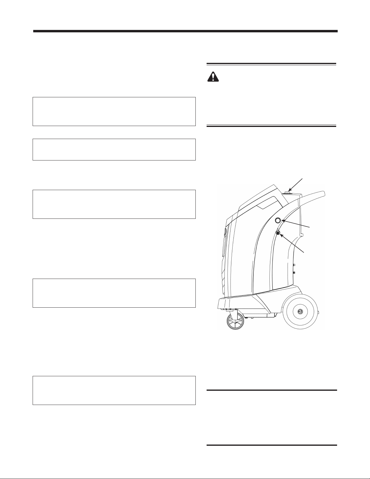
Figure 25
Oil Drain
Fitting
Oil Fill Cap
and Port
Sight
Glass
CAUTION: To prevent personal
injury, do NOT operate the machine at
any other time without the oil ll port
cap installed, because the vacuum pump
is pressurized during normal operation.
Caution:
It is the responsibility of the user
to
monitor vacuum pump oil level and
clarity. If contaminated oil is not removed
from the vacuum pump and replaced,
the vacuum pump will be permanently
damaged.
Change Vacuum Pump Oil
1.SelectCHANGE VACUUM PUMP OILfromthe
Setupmenuorwhenprompted.Thedisplayshows
howlongthevacuumpumphasoperatedsincethe
lastoilchange.
OILLIFETIME
XHOURSXMINUTES
CHANGEOIL?
2.PressOK.Ifthemachinedisplays
OILCHANGE
WAIT...
allowthevacuumpumptorunfor30seconds
towarmuptheoil.Iftheoilisalreadywarm,the
displayshows
OILCHANGE
UNITCLEARING
WAIT
whilethecompressorrunstoeliminateanypressure
inthevacuumpump.
3.Afterthecompressorstops,slowlyopentheoilll
captoverifythereisnopressureinthemachine.
Thencarefullyremovethecap.SeeFigure25.
4.Thedisplayshows
DRAINTHEUSEDPUMPOIL
ATTHEENDADDABOUT150MLOFNEWOIL
PRESSOKTOCONFIRM
Removetheoildrainttingcap,anddraintheoilinto
asuitablecontainerfordisposal.Replacethecap
andclosetightly.
5.
S
lowlyaddapproximately
150mlofvacuumpump
oiltothepumpthroughtheoilllport.PressOK to
startthevacuumpump.
6.Thedisplayshows
POUROILINTHEPUMP
UPTOTHECORRECTLEVEL
PRESSESCTOQUIT
S
lowlyadd
vacuumpump
oiltothepumpthrough
theoilllportuntiltheoillevelrisestothecenterof
thesightglass.
7.
Installthecapontheoilllportandclosetightly
.
PressESC.
36
Maintenance
Edit Print Header
Tomakechangestothetextthatappearsintheheader
oneachprintout:
1.SelectGARAGE DATAfromtheSetupmenu.
2.Thecursorisblinkinginthersteld.Pressthe
Menukeytodisplayavirtualkeyboard.
3.Usethearrowkeystomovearoundthekeyboard.
PressOKtoenteracharacter.
4.PresstheMenukeytoexitthekeyboardandmove
tothenextlleld.
5.PressOKtosavethedataandpressESCtoexitthe
keyboard.
ThisprocedureisexplainedinmoredetailintheSetup
sectionofthismanualunderGarageData.
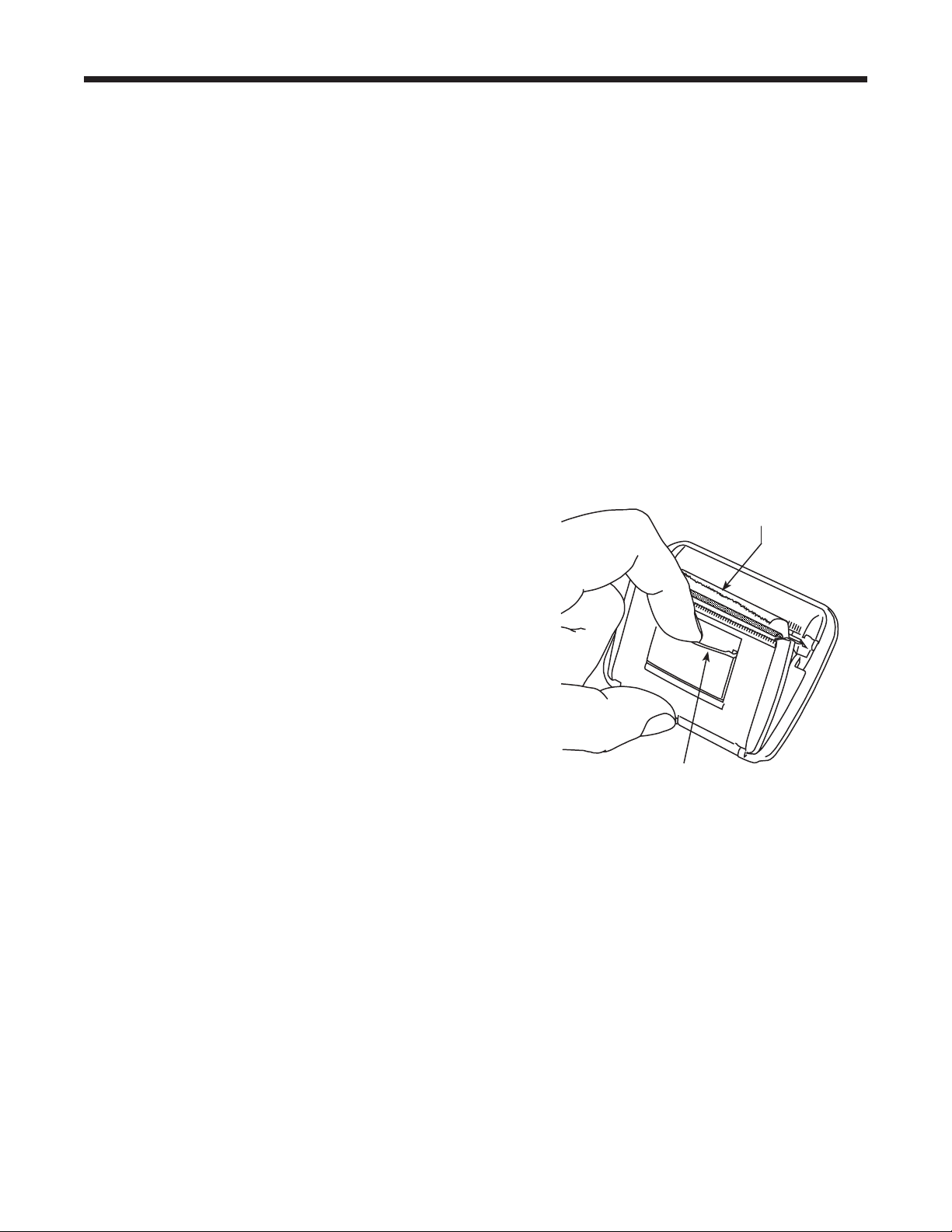
Replace Printer Paper
Toinstallanewpaperrollintheprinter:
1.Removethecoverontheprinterbypullingouton
thetabasshowninFigure26.
2.Removethepapercore.
3.Installthenewrollofpaperwiththeendofthepaper
atthetopoftheroll.
4.Assemblethecoverontotheprinterwiththeleading
edgeofthepaperovertheroller.
Tab
Leading Edge of
Paper Over Roller
Figure 26
Replace Service Hoses
and / or Service Couplers
Ensurepressurehasbeenremovedfromservice
hosesbeforedisconnectingahoseorcouplerfrom
themachine.Pressuregaugesmustreadator
below0psig.
Ifpressureexists,recovertherefrigerantfromthe
hosesbeforedisconnectingahoseorcoupler.
37
AC1234-6 Rev. C
Component Replacement Part No.
CalibrationWeight 16214
ContaminatedRefrigerantTank(optional) 17990
Filter 34724
FilterMaintenanceKit 13172
(includes lter and vacuum pump oil)
IdentierFilter 16913
IdentierOxygenSensor 16916
IdentierSampleHoseAssembly 16106
OilDrainBottle 19100
PrinterPaper(1roll) 34214
ServiceCoupler,High-Side(red) 18123
ServiceCoupler,Low-Side(blue) 18122
ServiceCouplerSet 18124
(high-side [red] and low-side [blue)] couplers)
ServiceHose(low-side, blue) 70123
ServiceHose(high-side, red) 70124
ServiceHoseSet 71234
(high-side [red] and low-side [blue)] hoses)
TankFillHoseFilter 10233
VacuumPumpOil(quart) 13203
VacuumPumpOil(gallon) 13204
VinylDustCover(optional) 17499
Parts List
CAUTION: To prevent
personal injury, use only
those repair parts called out
in this parts list. Items found
in this parts list have been
carefully tested and selected
by Robinair.
Replacement Parts and Glossary
Glossary
A/C System :Thevehicleairconditioningsystembeingserviced.
Evacuation :Moistureandothernon-condensablesareremovedfromanA/Csystembyavacuum
pumpcapableofpullingthesystemto5mbarabsolute.
Internal Storage Vessel (ISV) :Therellablerefrigerantstoragetankdesignedspecicallyforthis
machine;9.09kg(20.04lb.)capacity.
Leak Test (Vacuum) : Componentscontainingrefrigerantareevacuatedandmonitoredforpressure
rise,whichcouldindicatealeak.
Machine :ModelNo.AC1234-6.
PAG : PolyalkyleneGlycol
POE : PolyesterOil
Recovery / Recycling :RefrigerantisrecoveredfromanA/Csystem,ltered,andstoredintheISV.
Refrigerant :R1234yf.
38
Software Flow Chart
Setup
Functions
RRR
Database
Update
Product Activation
Menu
Service
Language Selection
System Information
Unit of Measure
Change Vacuum Pump Oil
Filter Change
Refrigerant Management
Tank Filling
Tank Fill Adjustment
Default Charge Target
Calibration Check
Beeper Setting
Air Purge Info
Garage Data
Date and Time Setup
Backlight
Recovery
Vacuum
Charge
Automatic
System Flush
Diagnostic Pressures
Tank Filling
System Information
Legal
Date and Time Setup
Instantaneous
Stored Data
Update Application
Update Db
Print Data Record
Delete Data Record
Clear All Data
Video Instruction
Hose Flush

39
AC1234-6 Rev. C
Troubleshooting Messages
Display Cause Solution
AIRFLOWERROR
Fanisnotworking.Airowis
blocked.
Exit current test. Contact Robinair
authorized service center.
ANALYZERERROR1
UNSTABLEOUTPUT
1.Insufcientrefrigerantowto
identier.
2.Possibleelectromagnetic
orRF(radiofrequency)
interference.
1. Check source tank for
pressure and secure valve
connections.
2. Move unit away from EMF or
RFI sources.
ANALYZERERROR2
HIGHOUTPUT
PossibleelectromagneticorRF
(radiofrequency)interference.
Move unit away from EMF or
RFI sources.
ANALYZERERROR3
AIRCALIBRATIONLOW
Possiblerefrigerantinexternal
calibrationair.
Check air ventilation and air
ow.
ANALYZERERROR4
IDENTIFIEROUTOF
TEMPERATURERANGE
Identiertemperatureoutside
operatingrange.
Check unit ventilation and
ambient conditions.
ANALYZERERROR5
REPLACEIDENTIFIER
FILTERANDSAMPLEHOSE
ASSEMBLY
1.Insufcientrefrigerantowto
identier.
2.Samplehoseorlterinside
refrigerantidentieris
pluggedorcontaminated
withoil.
1. Check source tank for
pressure and secure valve
connections.
2.
Follow maintenance
procedure to change identier
lter and sample hose.
CHARGEINPROGRESS
AIRPURGE
Non-condensablegasis
presentinISVthatcould
contaminateA/Csystem.
Before it charges, the machine
purges air out of the ISV.
EMPTYSOURCETANK
1.Machinesenseslow
pressure.
2.Filterintankllhoseis
plugged.
1. Check source tank for
pressure and secure valve
connections.
2. Refer to Tank Fill Hose
Service in Maintenance
section.
INSUFFICIENTPRESSURE
Ifpressureislessthan0.7bar,
refrigerantcannotbeidentied.
Refer to Vacuum section; follow
instructions to evacuate system.
ISVCONDITION
Machineiscirculating
refrigeranttobuildISVpressure
forachargecycle.
Charge process is automatically
interrupted and machine
operates in a mode to build
tank pressure. Once tank
pressure is sufcient, machine
automatically completes charge.

40
Troubleshooting Messages
Troubleshooting Messages continued
Display Cause Solution
OILOUTOFLIMIT
Vacuumpumphasrunfor10
hours;vacuumpumpoilshould
bereplaced.
Refer to Change Vacuum Pump
Oil in the Maintenance section
for instructions.
PRESSURETOOHIGH
Excessivepressurehasbeen
detected.
Press ESC. Refer to Recovery
section and recover refrigerant
before proceeding.
PURITYTESTFAILED
Refrigerantinvehicleis
eithernotR1234yforitis
contaminated.
Refer to Troubleshooting
Procedures section. Use 25700
external recovery machine to
recover refrigerant.
PURITYTESTFAILED
100%AIR
1.Insufcientrefrigerantowto
identier.
2.Excessiveairinsourcetank.
1. Check source tank for
pressure and secure valve
connections.
2. Replace source tank with
good refrigerant.
REFRIGERANTINSUFF
AfterselectingCHARGEand
enteringadesiredweight,ifthe
weightenteredwillleaveless
than.91kg(2lbs.)ofrefrigerant
inISVaftercharge,charge
functionwillnotstart.
Refer to Manually Fill the
Internal Storage Vessel (ISV) in
the Maintenance section.
REPLACEIDENTIFIERFILTER
1.Filterinsiderefrigerant
identierisplugged.
2.Filterintankllhoseis
plugged.
1. Refer to Maintenance section
for instructions to change
identier lter.
2. Refer to Tank Fill Hose
Service in Maintenance
section.
SYSTEMPRESSURETOO
LOW
Ifpressureislessthan0.7
bar,therefrigerantcannotbe
identied.
If vehicle is very cold, allow
vehicle to warm up and retest.
Otherwise enter Vacuum mode
and evacuate system.
VACUUMDECAYTEST
FAILED
AleakinthevehicleA/C
system.
Exit current test and perform
repairs on the vehicle A/C
system.
41
AC1234-6 Rev. C
Setup, Tank Fill, and Background Tank Fill Functions
Troubleshooting Procedures
Display Message: PURITY TEST FAILED
DuringSETUP,TANK FILL,orBACKGROUND
TANK FILL,ifthemachinedisplays
PURITYTESTFAILED
RECOVERCONTAMINATED
REFRIGERANTFROMSYSTEM
ANDHOSES.
OKTORETRYESCTOQUIT
therefrigerantinthesourcetankiseithernot
R1234yforitiscontaminated.Ineithercase,
itshouldnotbeaddedtotheinternalstorage
vessel(ISV)inthemachine.Thecontaminated
refrigerantsampledbytherefrigerantidentierin
themachinemustberemoved.
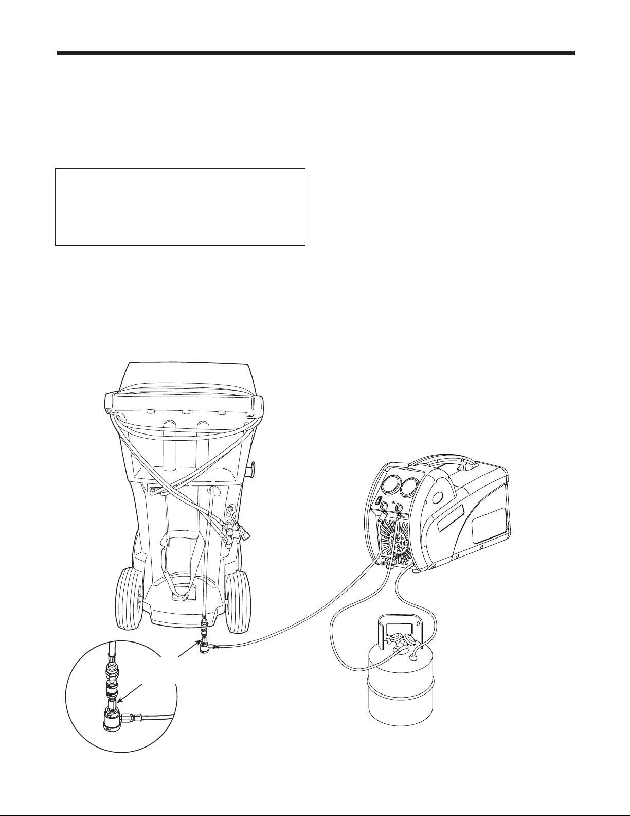
A refrigerant recovery machine (No. 25700)
dedicated to contaminated refrigerant is
required for the following steps. Refer to
Figure 27.
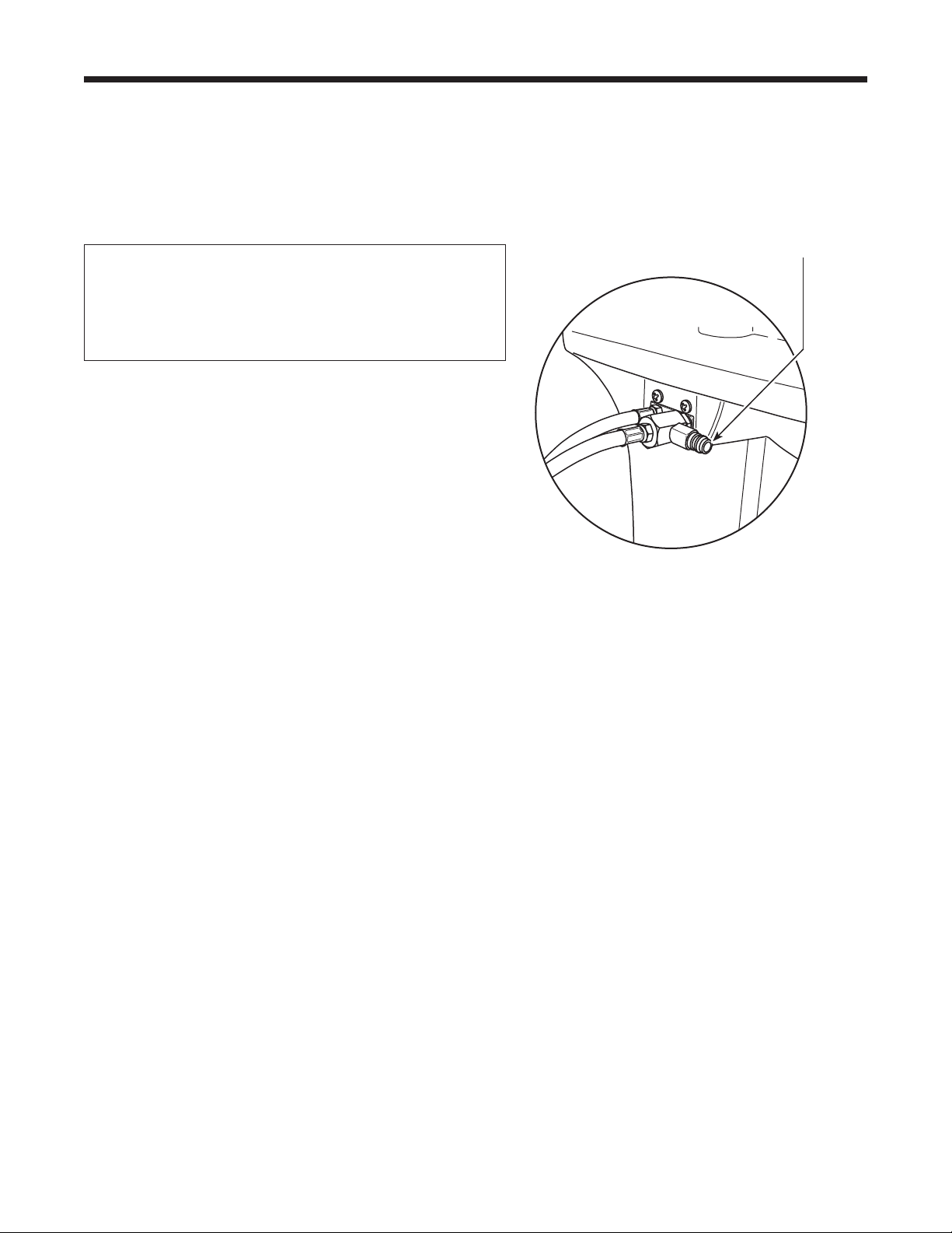
1.Connectthetankllhoseadapter(providedin
theAccessoryKit)tothelow-sidecouplerof
the25700refrigerantrecoverymachine.
2.Connecttheotherendoftheadaptertothe
tankllhosettingontheAC1234-6.
3.Connectthedischargehosefromthe25700
toatankspeciedtoreceivecontaminated
refrigerant.
4.Startthe25700andopenthecouplervalve.
Runarecoveryuntilthegaugeonthe25700
indicatesvacuum.
5.Shutoffthe25700.
6.Slowlyandcarefullydisconnecttheadapter
fromthetankllhoseandthe25700.There
maystillbeasmallamountofpressureinthe
line.
No. 25700
Refrigerant Recovery Machine
No. 17990
Contaminated
Refrigerant Tank
Figure 27
Tank Fill Hose
Adapter
42
Recovery Function or Automatic Function
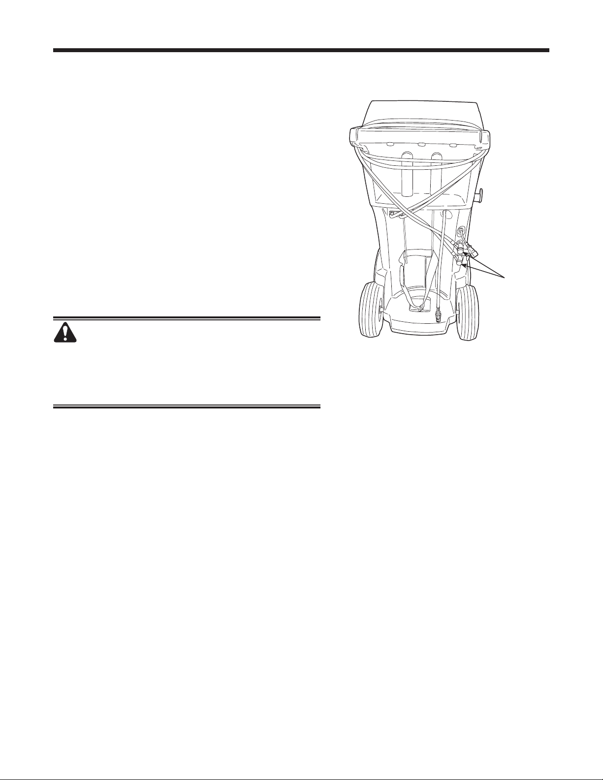
Figure 28
Troubleshooting Procedures
Connect No. 25700
contaminated refrigerant
recovery machine here.
Display Message: PURITY TEST FAILED
DuringtheRECOVERYfunctionorAUTOMATIC
RECOVERYfunction,ifthemachinedisplays
PURITYTESTFAILED
RECOVERCONTAMINATED
REFRIGERANTFROMSYSTEM
ANDHOSES.
OKTORETRYESCTOQUIT
therefrigerantinthesourcetankorinthevehicleA/C
systemiseithercontaminatedoritisnotR1234yf.
Ineithercase,itshouldnotbeaddedtotheinternal
storagevesselinthemachine.
Thecontaminatedrefrigerantsampledbythe
refrigerantidentierinthemachinemustberemoved.
A refrigerant recovery machine (No. 25700)
dedicated to contaminated refrigerant is required
for the following steps:
1.Withthemachinestillconnectedtothevehicle
andthecouplersopen,connectthelow-side(blue)
couplerfromthe25700tothecontaminantrecovery
portonthebackoftheAC1234-6.SeeFigure28.
Openthecouplervalves.
2.Connectthedischargehosefromthe25700toa
tankdesignedtoreceivecontaminatedrefrigerant.
3.Startthe25700andrunarecoveryaccordingto
instructionssuppliedwiththemachine.
4.Uponachievingavacuuminthevehicle(orper
recoverymachineinstructions),disconnectthe
25700fromtheAC1234-6.
5.Clearthevehicleofresidualcontaminationaccording
tothevehiclemanufacturer’sinstructionsbefore
continuingservice.

43
AC1234-6 Rev. C
Recovery Function
Display Message: SYSTEM EMPTY
Ifsystempressureisbelow0bargauge,untilpressure
increases,thedisplayreads
SYSTEMEMPTY
CHECKCONNECTIONS
RECOVERANYWAY?
Verifyhigh-side(red)andlow-side(blue)hosesare
connectedandcouplervalvesopen.PressOKto
recover,selectVACUUMtobypassRECOVER,or
pressESCtoexit.
Display Message: Filter Weight XXX LB
If100kg(220lbs.)ormoreofrefrigeranthasbeen
recoveredsincelastlterchange,displayreads
FILTERWEIGHTXXXLB
Tomeetrequirements,itismandatorytoreplacethe
lterafter150kg(331lbs.)ofrefrigeranthasbeen
ltered.Themachinegivesawarningtoreplacethe
lterwhenlterweightreaches100kg(220lbs.);when
lterweightreaches150kg(331lbs.),themachine
locksoutandceasestooperate.RefertoReplace the
FilterintheMaintenancesection.
Display Message: Replace Identier Filter
Ifthemachinedisplays
REPLACEIDENTIFIERFILTER
OKTOCONFIRM
thelterinsidetherefrigerantidentierneedsto
bereplaced.PressOKtoconrm,andrefertothe
Maintenancesectionofthismanualforinstructions.
Troubleshooting Procedures

44
Vacuum Function
Display Message: PRESSURE TOO HIGH
BeforethemachinebeginsevacuatingtheA/Csystem,
itchecksforpressureinthesystemthatmightdamage
thevacuumpump.Ifpressuregreaterthan0.7baris
detected,themachinedisplays
PRESSURETOOHIGH
CHECKCONNECTIONS
SelectOK,andrecoverrefrigerantbeforeproceeding.
Display Message: Vacuum Time X:XX Min
Ifaleaktestwasprogrammed,andaleakisdetected,
themachinedisplays
VACUUMTIMEX:XXMIN
LEAKTESTRESULTNEGATIVE
PressESCtoexittheautomaticsequenceandperform
neededrepairs.PressOKtocontinuetheautomatic
sequencedespitethefailedleaktest.
Toensureanaccurateleaktest,itisimperativethat
athoroughrecoveryandevacuationofthesystembe
performed.Duringtherecoveryprocess,coldspotscan
developintheA/Csystem.Pocketsofrefrigerantin
desiccantandinsystemoilwillcontinuetovaporizeas
theA/Csystemtemperatureequalizestowardambient.
Asthisoccurs,A/Csystempressurewillincrease,
whichmaybeinterpretedbythemachineasaleak.
Thiswillvarysomewhatwithambienttemperature
conditions.
Troubleshooting Procedures

45
AC1234-6 Rev. C
Automatic Function, System Flush, or Charge Function
Troubleshooting Procedures
Display Message: REFRIGERANT INSUFF
Iftheweightenteredismorethantherefrigerant
availableintheISV,thechargefunctionwillnotstart.
Thedisplayreads
REFRIGERANTINSUFF
RefertoManuallyFilltheISVintheMaintenance
section.
Display Message: PRESSURE TOO HIGH
FOR VACUUM
BeforethemachinebeginsevacuatingtheA/Csystem
duringtheautomaticsequence,itchecksforany
pressureinthesystemthatmaydamagethevacuum
pump.Ifpressureisdetected,themachinedisplays
PRESSURETOOHIGHFORVACUUM!
PressESC.Recoverrefrigerantbeforeproceeding.
Display Message: VACUUM TIME X:XX MIN
Ifaleaktestwasprogrammed,andaleakisdetected,
themachinedisplays
VACUUMTIMEX:XXMIN
LEAKTESTRESULTNEGATIVE
PressESCtoexittheautomaticsequenceandperform
neededrepairs.PressOKtocontinuetheautomatic
sequencedespitethefailedleaktest.
Display Message: PURITY TEST FAILED
RefertoTroubleshooting Procedures, Recovery
Function and Automatic Function.
Information
Toensureanaccurateleaktest,itisimperativethat
athoroughrecoveryandevacuationofthesystemis
performed.Duringtherecoveryprocess,coldspotscan
developintheA/Csystem.Pocketsofrefrigerantin
desiccantandinsystemoilwillcontinuetovaporizeas
theA/Csystemtemperatureequalizestowardambient.
Asthisoccurs,A/Csystempressureincreases,which
maybeinterpretedbythemachineasaleak.This
variessomewhatwithambienttemperatureconditions.
46
Storage and Transportation of Equipment
Storage
Neverleavethemachineliveifanimmediateuseisnot
scheduled.
1.Disconnectthemachinefromitspowersupply.
2.Looptheservicehosesaroundthehandletwiceand
attachthemtothestorageports.SeeFigure30.
3.Storethemachineinadry,stablearea,awayfrom
amesandhotsurfaces.Thetemperatureofthe
storageareashouldrangebetween-18°Cand66°C
(0°Fand150°F).
4.Lockthefrontwheels.
Transportation of Equipment
WARNING: To prevent personal injury should
the machine require transport to a local Robinair
service center, follow local government regulations
regarding transportation of equipment containing
R1234yf.
Figure 29
Hose
couplers
connected
to storage
ports.

Rev. November 1, 2005
This product is warranted to be free from
defects in workmanship, materials, and
components for a period of one year from date
of purchase. All parts and labor required to
repair defective products covered under the
warranty will be at no charge. The following
restrictions apply:
1. The limited warranty applies to the original
purchaser only.
2. The warranty applies to the product in
normal usage situations only, as described in
the Operating Manual. The product must be
serviced and maintained as specied.
3. If the product fails, it will be repaired or
replaced at the option of the manufacturer.
4. Transportation charges for warranty
service will be reimbursed by the factory
upon verication of the warranty claim
and submission of a freight bill for
normal ground service. Approval from the
manufacturer must be obtained prior to
shipping to an authorized service center.
5. Warranty service claims are subject to
authorized inspection for product defect(s).
6. The manufacturer shall not be responsible
for any additional costs associated with a
product failure including, but not limited
to, loss of work time, loss of refrigerant,
cross-contamination of refrigerant, and
unauthorized shipping and/or labor charges.
7. All warranty service claims must be made
within the specied warranty period. Proof-
of-purchase date must be supplied to the
manufacturer.
8. Use of recovery/recycling equipment with
unauthorized refrigerants or sealants will
void warranty.
• Authorized refrigerants are listed on the
equipment or are available through the
Technical Service Department.
• The manufacturer prohibits the use of
the recovery/recycling equipment on air
conditioning (A/C) systems containing
leak sealants, either of a seal-swelling or
aerobic nature.
This Limited Warranty
does NOT apply if:
• The product, or product part, is broken by
accident.
• The product is misused, tampered with, or
modied.
• The product is used for recovering or
recycling any substance other than the
specied refrigerant type. This includes, but
is not limited to, materials and chemicals
used to seal leaks in A/C systems.
Robinair
Limited Warranty Statement
Declaración de garantía
limitada Robinair
Revisión del 1 de noviembre de 2005
Se garantiza que este producto no posee
defectos de mano de obra, materiales y
componentes por el período de un año a
partir de la fecha de compra. Todas las partes
y mano de obra requerida para reparar los
productos con defecto cubiertos bajo la garantía
no tendrán costo. Aplican las siguientes
restricciones:
1. La garantía limitada aplica al comprador
original únicamente.
2. La garantía aplica al producto en situaciones
de uso normal únicamente, como lo indica
el Manual de funcionamiento. Al producto
se le debe dar servicio y mantenimiento
como se especica.
3. Si falla el producto, se debe reparar o
reemplazar a discreción del fabricante.
4. Los cargos de transporte de servicio de
garantía serán reembolsados por la fábrica
al vericar el reclamo de garantía y
presentar una boleta de ete por servicio
terrestre regular. Se debe obtener la
aprobación del fabricante antes de hacer el
envío a un centro de servicio autorizado.
5. Los reclamos de servicio de garantía
están sujetos a inspección de defectos del
producto.
6. El fabricante no será responsable de los
costos adicionales relacionados con fallas
en el producto, que incluyen pero no se
limitan a, tiempo improductivo, pérdida de
refrigerante, contaminación de refrigerante
y envío no autorizado o cargos por mano de
obra.
7. Todo reclamo de servicio de garantía se
debe hacer dentro del período de garantía
establecido. Se debe proporcionar la fecha
de la prueba de compra al fabricante.
8. El uso de equipo de recuperación/reciclaje
con refrigerantes o selladores no autorizados
anula la garantía.
• Los refrigerantes autorizados se indican
en el equipo o están disponibles a través
del Departamento de servicio técnico.
• El fabricante prohíbe el uso de equipo
de recuperación/reciclaje en sistemas de
aire acondicionado (A/C) con fugas de
sellador, ya sea porque un sello se ina o
es de naturaleza aeróbica.
Esta garantía limitada
NO aplica si:
• El producto, o parte de éste, se rompe
accidentalmente.
• El producto se usa incorrectamente, se
adultera o modica.
• El producto se usa para recuperar o reciclar
cualquier sustancia que sea diferente al tipo
de refrigerante establecido. Esto incluye,
pero no se limita a materiales y productos
químicos utilizados para sellar fugas en
sistemas de A/C.
Énoncé de la garantie limitée
de Robinair
Révisée le 1er novembre 2005
Ce produit est couvert contre les défauts de
matériau, de fabrication et de composant
pendant un an à compter de la date d’achat.
Toutes les pièces et la main-d’œuvre
nécessaires aux réparations sous garantie sont
sans frais. Toutefois, les restrictions suivantes
s’appliquent :
1. La garantie limitée s’applique uniquement à
l’acheteur initial.
2. La garantie s’applique uniquement au
produit utilisé dans des conditions de
fonctionnement normales conformément au
manuel d’utilisation. Il doit être réparé et
entretenu conformément aux spécications.
3.
Si le produit subit une défaillance, il sera
réparé ou remplacé à la discrétion du fabricant.
4. Les frais de transport pour les réparations
sous garantie sont remboursés par l’usine
après l’évaluation de la réclamation au
titre de la garantie et après la soumission
d’une facture de transport terrestre standard.
L’approbation du fabricant est requise
avant l’expédition du produit à un atelier de
réparation autorisé.
5. Les réclamations au titre de la garantie sont
sujettes à l’inspection du produit défectueux
par un personnel autorisé.
6.
Le fabricant ne peut être tenu responsable pour
tout coût supplémentaire lié à la défaillance
du produit incluant, sans toutefois s’y limiter,
les interruptions de fonctionnement, la perte
de liquide frigorigène, la contamination des
liquides frigorigènes et l’expédition et/ou les
frais de main-d’œuvre soumis par des ateliers
non autorisés.
7. Toute réclamation pour des réparations au
titre de la garantie doit être soumise durant
la période de garantie. Une preuve d’achat
doit être fournie au fabricant.
8.
L’utilisation d’un appareil de récupération et
de recyclage avec du liquide frigorigène ou
des scellants non spéciés annule la garantie.
•
Les liquides frigorigènes autorisés sont
indiqués sur l’appareil, ou ils peuvent
être obtenus auprès du Service technique.
•
Le fabricant interdit l’utilisation d’un
appareil de récupération et de recyclage
dans les systèmes de climatisation contenant
des colmatants pour fuites, que ce soient des
scellants à dilatation ou aérobiques.
Cette garantie limitée NE
s’applique PAS si le produit :
• ou une partie du produit a été endommagé
par un accident.
• a été utilisé de façon inadéquate, ou qu’il a
été altéré ou modié.
• est utilisé pour la récupération et le
recyclage de substances autres que le
type de liquide frigorigène spécié. Ces
substances comprennent, sans toutefois
s’y limiter, les matériaux et les produits
chimiques utilisés pour colmater les fuites
des systèmes de climatisation.

567817 (Rev. C, November 10, 2014) © Bosch Automotive Service Solutions LLC
The Robinair unit is designed to meet all applicable agency certications, including Underwriter's Laboratories, Inc., SAE Standards,
and CUL. Certain state and local jurisdictions dictate that using this equipment to sell refrigerant by weight may not be permitted.
We recommend charging for any A/C service by the job performed. This weight scale provides a means of metering the amount of
refrigerant needed for optimum A/C system performance as recommended by OEM manufacturers.
La unidad Robinair está diseñada para cumplir con todas las certicaciones de agencia aplicables, incluyendo Underwriter's Laboratories,
Inc., Estándares SAE y CUL. Ciertas jurisdicciones estatales y locales prescriben que el uso de este equipo para vender refrigerante
por peso es posible que no sea permitido. Recomendamos que se cobre el trabajo realizado por dar servicio al aire acondicionado.
Esta escala de peso proporciona un medio para medir la cantidad de refrigerante que se necesita para el rendimiento óptimo del
sistema de aire acondicionado, tal como lo recomiendan los fabricantes OEM.
La machine Robinair a été conçue pour répondre à toutes les certications applicables, y compris celles de l’organisation Underwriters
Laboratories, Inc., ainsi qu’aux normes SAE et CUL. Certaines juridictions nationales et locales n’autorisent pas l’utilisation de cet
équipement pour vendre du réfrigérant au poids. Nous recommandons de facturer l’entretien du système de climatisation en fonction
du travail effectué. Ce poids de tarication permet de calculer la quantité de réfrigérant requise pour garantir le fonctionnement optimal
du système de climatisation, conformément aux recommandations des fabricants de l’équipement d’origine.
Due to ongoing product improvements, we reserve the right to change design, specications, and materials without notice.
Debido a las constantes mejoras del producto, nos reservamos el derecho de cambiar diseño, especicaciones y materiales sin aviso.
En raison des améliorations constantes apportées à nos produits, nous nous réservons le droit de modier la conception, les spécications et les matériaux sans préavis.
655 EISENHOWER DRIVE
OWATONNA, MN 55060-0995 USA
TECH SERVICES 800 822 5561
FAX 866 259 1241
CUSTOMER SERVICE 800 533 6127
FAX 800 322 2890
www.robinair.com
