
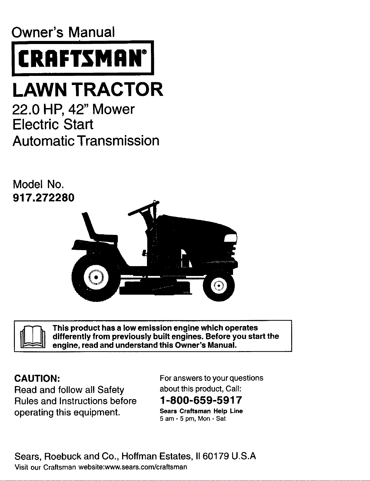
Owner's Manual
LAWN TRACTOR
22.0 HP, 42" Mower
Electric Start
Automatic Transmission
Model No.
917.272280
I_ This product has a low emission engine which operates I
I
differently from previously built engines. Before you start the
I
engine, read and understand this Owner's Manual.
CAUTION:
Read and follow all Safety
Rules and Instructions before
operating this equipment.
For answers to your questions
about this product, Call:
1-800-659-5917
Sears Craftsman Help Line
5 am - 5 pro, Mon- Sat
Sears, Roebuck and Co., Hoffman Estates, II60179 U.S.A
Visit our Craftsman website:www.sears.com/craftsman
Warranty ............................................... 2
Safety _ules ......................................... 3
Product Specifications .......................... 6
AssemblyPre-Operation ....................... 8
Operation ............................................ 11
Maintenance ....................................... 18
Maintenance Schedule ...................... 18
Service and Adjustments .................... 22
Storage ............................................... 29
Troubleshooting ................................. 30
Repair Parts ........................................ 34
Sears Service ...................... Back Cover
LIMITED WARRANTY ON CRAFTSMAN RIDING EQUIPMENT
For two (2) years from the date of purchase, if this Craftsman Riding Equipment is
maintained, lubricated and tuned up according to the instructions in the owner s
manual, Sears will repair or replace free of charge any parts that are found to be
defective in material or workmanship according to the guidelines of coverage listed
below. Sears will also provide free labor for these applicable warranted parts for the
two fullyears. During the first 30 days of purchase, there will be no charges to service
the product at your home for issues covered by this warranty. (See exclusions below).
For your convenience, IN HOME warranty service will still be available after the first 30
clays of purchase, but a trip charge will apply. This charge will be waived if the Crafts-
man product is dropped off at an authorizedSears location. For the nearest authorized
Sears location, please call 1-800-4-MY-HOME®. This warranty applies only while this
product is within the United States.
This Warranty does not cover:
• Expendable items which become worn during normal use, including but not limited
to blades, spark plugs, air cleaners, belts, and oil filters.
• Standard Maintenance Servicing, oil changes, or tune-ups
• Tire replacement or repair caused by punctures from outside objects, such as nails,
thorns, stumps, or glass.
i epairs necessary because of operator abuse, includin9 but not limited to, damage
caused by towing objects beyond the capability of the nding equipment, impacting
objects that bendthe frame or crankshaft, or over-speeding the engine.
Repairs necessary because of operator negligence, including but not limited to,
electrical and mechanical damage caused by improper storage, failure to use the
proper grade and amount of engine oil, failure to keep the deck clear of flammable
debris, or failure to maintain the equipment according to the instructions contained in
the owner's manual.
• Engine (fuel system) cleaning or repairs caused by fuel determined to be contami-
nated or oxidized (stale). In general, fuel should be used within 30 days of its
purchase date.
• Normal deterioration and wear of the exterior finishes, or product label replacement.
• Riding equipment used for commercial or rental purposes.
LIMITED WARRANTY ON BATTERY
For ninety (90) days from date of purchase, if any battery included with this riding
equipment proves defective in material or workmanship and our testing determines the
battery will not hold a charge, Sears will replace the battery at no charge. During the
first 30 days of purchase, there will be no charges to replace the battery at your HOME.
After the first 30 days, for your convenience, IN-HOME warranty service will still be
available but a trip charge will apply. This charge will be waived if the Craftsman
product is dropped of at an authorized Sears location. For the nearest authorized
Sears location, please call 1-800-4-MY-HOME®.
This battery warranty applies only while this product is within the United States.
This warranty gives you specific legal rights, and you may also have other rights, which
vary, from state to state.
Sears, Roebuck and Co.,Dept.817WA, Hoffman Estates, IL 60179
2
IMPORTANT: This cutting machine is capable of amputating hands and feet and
throwing, objects. Failure to observe the following safety instructions could result in
serious injury or death.
Look for this symbol to point out
important safety precautions. It means
CAUTION!fl BECOMEALERT!!! YOUR
SAFETY IS INVOLVED.
_, CAUTION: In order to prevent
accidental starting when setting up,
transporting, adjusting or making repairs,
always disconnect spark plug wire and
place wire where it cannot contact spark
plug.
CAUTION: Do not coast down a hill
in neutral, you may lose control of the
tractor.
CAUTION: Tow only the attachments
that are recommended by and comply
with specifications of the manufacturer of
your tractor. Use common sense when
towing. Operate only at the lowest
possible speed when on a slope. Too
heavy of a load, while on a slope, is
dangerous. Tires can lose traction with
the ground and cause you to lose control
of your tractor.
WARNING: Engine exhaust, some of
its constituents, and certain vehicle
components contain or emit chemicals
known to the State of California to cause
cancer and birth defects or other repro-
ductive harm.
WARNING: Battery posts, terminals
and related accessories contain lead
and lead compounds, chemicals known
to the State of California to cause cancer
and birth defects or other reproductive
harm. Wash hands after handling.
I. GENERAL OPERATION
• Do not mow in reverse unless absolutely
necessary. Always look down and
behind before and while backing.
• Be aware of the mower discharge
direction and do not point it at anyone.
Do not operate the mower without either
the entire grass catcher or the guard in
place.
• Slow down before turning.
• Never leave a running machine
unattended. Always turn off blades, set
parking brake, stop engine, and remove
keys before dismounting.
• Turn off blades when not mowing.
• Stop engine before removing grass
catcher or unclogging chute.
• Mow only in daylight or good artificial
light.
• Do not operate the machine while under
the influence of alcohol or drugs.
• Watch for traffic when operating near or
crossing roadways.
• Use extra care when loading or unload-
ing the machine into a trailer or truck.
• Data indicates that operators, age 60
years and above, are involved in a large
percentage of riding mower-related
injuries. These operators should
evaluate their ability to operate the riding
mower safely enough to protect them-
selves and others from serious injury.
• Keep machine free of grass, leaves or
other debris build-up which can touch
hot exhaust / engine parts and burn. Do
not allow the mower deck to plow leaves
or other debris which can cause build-
up to occur. Clean any oil or fuel
spillage before operating or storing the
machine. Allow machine to cool before
storage.
• Read, understand, and follow all
instructions in the manual and on the
machine before starting.
• Only allow responsible adults, who are
familiar with the instructions, to operate
the machine.
• Clear the area of objects such as recks,
toys, wire, etc., which could be picked
up and thrown by the blade.
• Be sure the area is clear of other people
before mowing. Stop machine if anyone
enters the area.
• Never carry passengers.
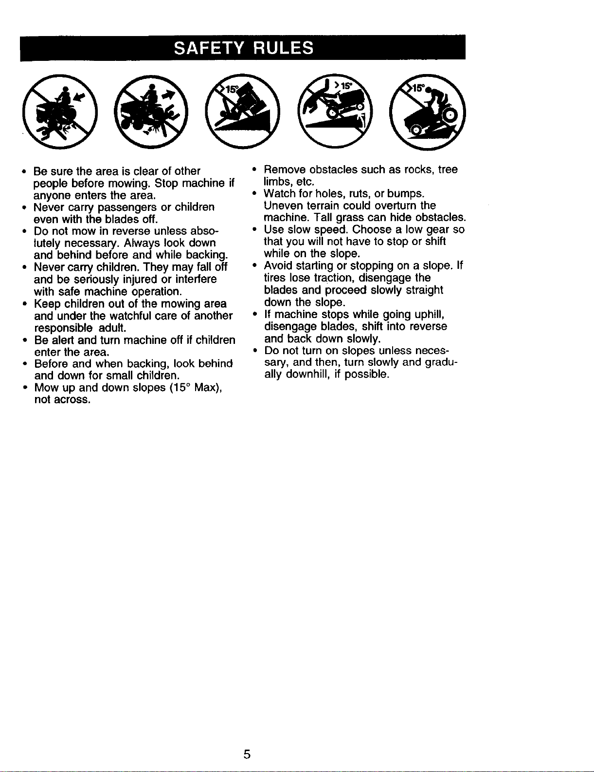
II. SLOPE OPERATION
Slopes are a major factor related to loss-of-
control and tipover accidents, which can re-
sult in severe injury or death. All slopes
require extra caution. If you cannot back up
the slope or if you feel uneasy on it, do not
mow it.
3

DO:
• Mow up and down slopes, not across.
• Remove obstacles such as rocks, tree
limbs, etc.
• Watch for holes, ruts, or bumps. Uneven
terrain could overturn the machine. Taft
grass can hide obstacles.
• Use slow speed. Choose a low gear so
that you will not have to stop or shift
while on the slope.
• Follow the manufacturer's recommenda-
tions for wheel weights or counter-
weights to improve stability.
• Use extra care with grass catchers or
other attachments. These can change
the stability of the machine.
• Keep all movement on the slopes slow
and gradual. Do not make sudden
changes in speed or direction.
• Avoid starting or stopping on a slope. If
tires lose traction, disengage the blades
and proceed slowly straight down the
slope.
DO NOT-
• Do not turn on slopes unless necessary,
and then, turn slowly and gradually
downhill, if possible.
• Do not mow near drop-offs, ditches, or
embankments. The mower could
suddenly turn over if a wheel is over the
edge of a cliff or ditch, or if an edge
caves in.
• Do not mow on wet grass. Reduced
traction could cause sliding.
• Do not try to stabilize the machine by
putting your foot on the ground.
• Do not use grass catcher on steep
slopes.
IlL CHILDREN
Tragic accidents can occur if the operator
is not alert to the presence of children.
Children are often attracted to the
machine and the mowing activity. Never
assume that children will remain where
you last saw them.
• Keep children out of the mowing area
and under the watchful care of another
responsible adult.
• Be alert and turn machine off if children
enter the area.
• Before and when backing, look behind
and down for small children.
• Never carry children. They may fall off
and be seriously injured or interfere
with safe machine operation.
• Never allow children to operate the
machine.
• Use extra care when approaching blinc
corners, shrubs, trees, or other objects
that may obscure vision.
IV,SERVICE
• Use extra care in handling gasoline
and other fuels. They are flammable
and vapors are explosive.
-Use only an approved container.
- Never remove gas cap or add fuel
with the engine running. Allow
engine to cool before refueling. Do
not smoke.
-Never refuel the machine indoors.
- Never store the machine or fuel
container inside where there is an
open flame, such as a water heater.
• Never run a machine inside a closed
area.
• Keep nuts and bolts, especially blade
attachment bolts, tight and keep
equipment in good condition.
• Never tamper with safety devices.
Check their proper operation regularly.
• Keep machine free of grass, leaves, or
other debris build-up. Clean oil or fuel
spillage. Allow machine to cool before
storing.
• Stop and inspect the equipment if you
strike an object. Repair, if necessary,
before restarting.
• Never make adjustments or repairs
with the engine running.
• Grass catcher components are subject
to wear, damage, and deterioration,
which could expose moving parts or
allow objects to be thrown. Frequently
check components and replace with
manufacturer's recommended parts,
when necessary.
• Mower blades are sharp and can cut.
Wrap the blade(s) or wear gloves, and
use extra caution when servicing them.
• Check brake operation frequently.
Adjust and service as required.
4
• Be sure the area is clear of other
people before mowing. Stop machine if
anyone enters the area.
• Never carry passengers or children
even with the blades off.
• Do not mow in reverse unless abso-
lutely necessary. Always look down
and behind before and while backing.
• Never carry children. They may fall off
and be seriously injured or interfere
with safe machine operation.
• Keep children out of the mowing area
and under the watchful care of another
responsible adult.
• Be alert and turn machine off if children
enter the area.
• Before and when backing, look behind
and down for small children.
• Mow up and down slopes (15 ° Max),
not across.
• Remove obstacles such as rocks, tree
limbs, etc.
• Watch for holes, ruts, or bumps.
Uneven terrain could overturn the
machine. Tall grass can hide obstacles.
• Use slow speed. Choose a low gear so
that you will not have to stop or shift
while on the slope.
• Avoid starting or stopping on a slope. If
tires lose traction, disengage the
blades and proceed slowly straight
down the slope.
• If machine stops while going uphill,
disengage blades, shift into reverse
and back down slowly.
• Do not turn on slopes unless neces-
sary, and then, turn slowly and gradu-
ally downhill, if possible.
5
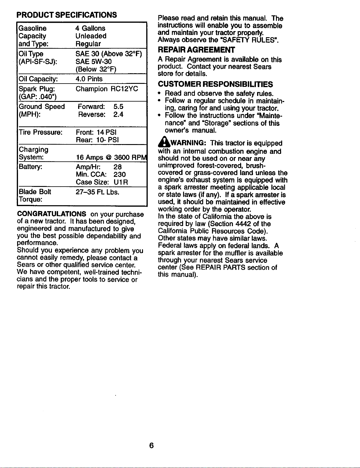
PRODUCT SPECIFICATIONS
Gasoline
Capacity
and Type:
OilType
API-SF-SJ):
Oil Capacity:
Spark Plug:
GAP: .040")
Ground Speed
(MPH):
4 Gallons
Unleaded
Regular
SAE 30 (Above 32°F)
SAE 5W-30
(Below 32°F)
4.0 Pints
Champion RC12YC
Forward: 5.5
Reverse: 2.4
Tire Pressure: Front: 14PSI
Rear: 10- PSI
Charging
System: 16 Amps @ 3600 RPM
Battery: Amp/Hr: 28
Min. CCA: 230
Case Size: Ul R
Blade Bolt 27-35 Ft. Lbs.
Torque:
CONGRATULATIONS on your purchase
of a new tractor. It has been designed,
engineered and manufactured to give
you the best possible dependability and
performance.
Should you experience any problem you
cannot easily remedy, please contact a
Sears or other qualified service center.
We have competent, well-trained techni-
cians and the proper tools to service or
repair this tractor.
Please read and retainthis manual. The
instructionswill enable you to assemble
and maintain yourtractorproperly.
Always observe the "SAFETY RULES".
REPAIR AGREEMENT
A Repair Agreement is available on this
product. Contact your nearest Sears
store for details.
CUSTOMER RESPONSIBILITIES
• Read and observe the safety rules.
• Follow a regular schedule in maintain-
ing, caringfor and usingyour tractor.
• Follow the instructionsunder "Mainte-
nance"and =Storage" sections of this
owner's manual.
_WARNING: This tractor is equipped
with an internal combustion engine and
should not be used on or near any
unimproved forest-covered, brush-
covered or grass-covered land unless the
engine's exhaust system is equipped with
a spark arrester meeting applicable local
or state laws (if any). If a spark arrester is
used, it should be maintained in effective
working order by the operator.
In the state of California the above is
required by law (Section 4442 of the
California Public Resources Code).
Other states may have similar laws.
Federal laws apply on federal lands. A
spark arrester for the muffler is available
through your nearest Sears service
center (See REPAIR PARTS section of
this manual).
6
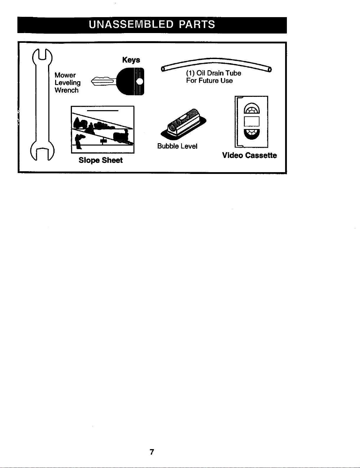
Mower
Leveling
Wrench
(1) Oil Drain Tube
For Future Use
Bubble Level
Slope Sheet
Video Cassette
7
Your new tractor hasbeen assembledat the factory. Reviewthe video cassettebefore
you begin.
When right or left hand is mentioned in
this manual, it means, from your point of
view, when you are in the operating
position (seated behind the steering
wheel).
TO REMOVE TRACTOR FROM
CARTON
UNPACK CARTON
1. Remove all accessible loose parts
and parts boxes from carton.
2. Cut, from top to bottom, along lines on
all four comers of carton, and lay
panels flat.
3. Check for any additional loose parts
or cartons and remove.
IMPORTANT: Check for and remove any
staples in skid that may puncture tires
where tractor is to roll off skid.
CHECK BATTERY
1. Lift hood to raised position.
NOTE: If this battery is put into service
after month and year indicated on label
(label located between terminals) charge
battery for minimum of one hour at 6-10
amps. (See "BATTERY" in Maintenance
section of this manual for charging
instructions).
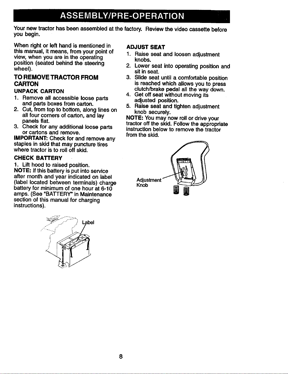
ADJUST SEAT
1. Raise seat and loosen adjustment
knobs.
2. Lower seat into operating position and
sit in seat.
3. Slide seat until a comfortable position
is reached which allows you to press
clutch/brake pedal all the way down.
4. Get off seat without moving its
adjusted position.
5. Raise seat and tighten adjustment
knob securely.
NOTE: You may now roll or drive your
tractor off the skid. Follow the appropriate
instruction below to remove the tractor
from the skid.
Knob
q
8
TO ROLL TRACTOR OFF SKID (See
Operation section for location and
function of controls)
1. Press lift lever plunger and raise
attachment lift lever to its highest
position.
2. Release parking brake by depressing
brake pedal.
3. Place freewheel control in disen-
gaged position to disengage transmis-
sion (See "TO TRANSPORT" in the
Operation section of this manual).
4. Roll tractor forward off skid.
5. Remove banding holding the deflector
shield up against tractor.
TO DRIVE TRACTOR OFF SKID (See
Operation section for location and
function of controls)
WARNING: Before starting, read
understand and follow a instructions in
the Operation section of this manual. Be
sure tractor is in a well-ventilated area. Be
sure the area in front of tractor is clear of
other people and objects.
1. Be sure all the above assembly steps
have been completed.
2. Check engine oil level and fill fuel
tank with gasoline.
3. Place freewheel control in "transmis-
sion engaged" position (see "TO
TRANSPORT" in Operation section of
this manual).
4. Sit on seat in operating position,
depress brake pedal and set the
parking brake.
5. Press lift lever plunger and raise
attachment lift lever to its highest
position.
6. Start the engine. After engine has
started, move throttle control to idle
position.
7. Release parking brake.
8. Slowly depress forward drive pedal
and drive tractor off skid.
9. Apply brake to stop tractor and set
parking brake.
10.Turn ignition key to "STOP" position.
Continue with the instructions that follow.
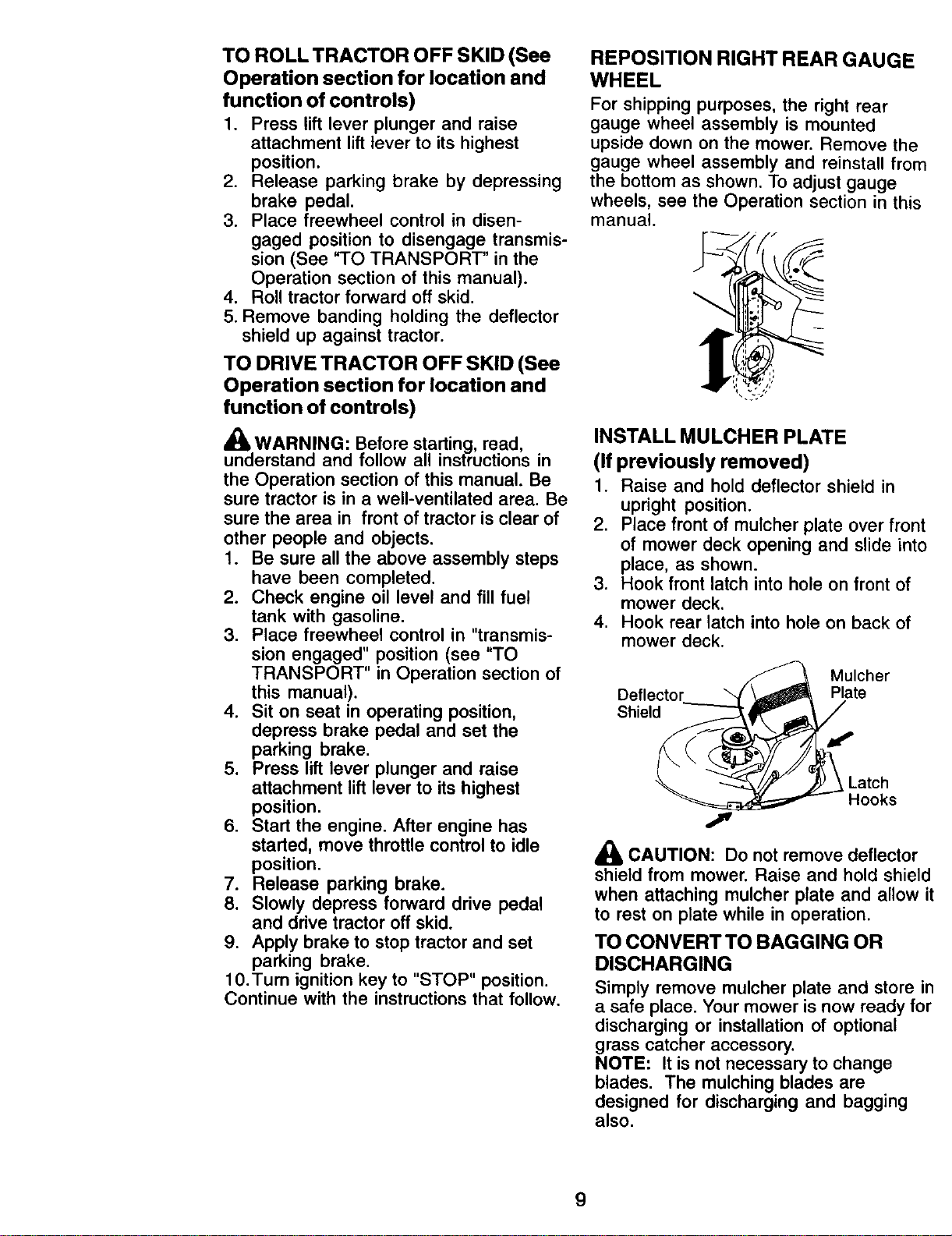
REPOSITION RIGHT REAR GAUGE
WHEEL
For shipping purposes, the right rear
gauge wheel assembly is mounted
upside down on the mower. Remove the
gauge wheel assembly and reinstall from
the bottom as shown. To adjust gauge
wheels, see the Operation section in this
manual.
INSTALL MULCHER PLATE
(If previously removed)
1. Raise and hold deflector shield in
upright position.
2. Place front of mulcher plate over front
of mower deck opening and slide into
place, as shown.
3. Hook front latch into hole on front of
mower deck.
4. Hook rear latch into hole on back of
mower deck.
Deflector
Shield
Mulcher
Plate
Latch
Hooks
_, CAUTION: Do not remove deflector
shield from mower. Raise and hold shield
when attaching mulcher plate and allow it
to rest on plate while in operation.
TO CONVERT TO BAGGING OR
DISCHARGING
Simply remove mulcher plate and store in
a safe place. Your mower is now ready for
discharging or installation of optional
grass catcher accessory.
NOTE: It is not necessary to change
blades. The mulching blades are
designed for discharging and bagging
also.
9
CHECK TIRE PRESSURE
The tires on your tractor were overinflated
at the factory for shipping purposes.
Correct tire pressure is important for best
cutting performance.
• Reduce tire pressure to PSI shown in
"PRODUCT SPECIFICATIONS" section
of this manual.
CHECK DECKLEVELNESS
For best cutting results, mower housing
should be properly leveled. See "TO
LEVEL MOWER HOUSING" in the
Service and Adjustments section of this
manual.
CHECKFORPROPERPOSITIONOF
ALLBE_S
See the figures that are shown for
replacing motion and mower blade drive
belts in the Service and Adjustments
section of this manual. Verify that the
belts are routed correctly.
CHECK BRAKE SYSTEM
After you learn how to operate your
tractor, check to see that the brake is
properly adjusted. See "TO ADJUST
BRAKE" in the Service and Adjustments
section of this manual.
,/CHECKLIST
Before you operate your new tractor, we
wish to assure that you receive the best
performance and satisfaction from this
quality product.
Please review the following checklist:
,/ All assembly instructions have been
completed.
,/No remaining loose parts in carton.
,/Battery is properly prepared and
charged. (Minimum 1 hour at 6 amps).
,/Seat is adjusted comfortably and
tightened securely.
,/All tires are properly inflated. (For
shipping purposes, the tires were
overinflated at the factory).
,I Be sure mower deck is properly leveled
side-to-side/front-to-rear for best cutting
results. (Tires must be properly inflated
for leveling).
,/Check mower and drive belts. Be sure
they are routed properly around pulleys
and inside all belt keepers.
,/Check wiring. See that all connections
are still secure and wires are properly
clamped.
,/Before driving tractor, be sure freewheel
control is in "transmission engaged"
position (see "TO TRANSPORT" in the
Operation section of this manual).
While learning how to use your tractor, pay
extra attention to the following important
items:
,f Engine oil is at proper level.
,/" Fuel tank is filled with fresh, clean,
regular unleaded gasoline.
,/Become familiar with all controls - their
location and function. Operate them
before you start the engine.
,/Be sure brake system is in safe operat-
ing condition.
,/It is important to purge the transmission
before operating your tractor for the first
time. Follow proper starting and trans-
mission purging instructions (See "TO
START ENGINE" and "PURGE TRANS-
MISSION" in the Operation section of this
manual).
10
These symbols may appear on your tractor or in literature supplied with the product.
Learn and understand their meaning.
BATTERY CAUTION OR
WARNING
REVERSE FORWARD FAST SLOW
ENGINE ON ENGfNE OFF OIL PRESSURE
LIGHTS ON
®
FUEL CHOKE MOWER HEIGHT PARKING BRAKE UNLOCKED
LOCKED
MOWERLJ_
R N H L
ATTACHMENT REVERSE
CLUTCH ENGAGED
NEUTRAL HIGH LOW
P'ARK{NG BRAKE
ATTACHMENT KEEP AREA CLEAR SLOPE HAZARDS
IGNITION CLUTCH DISENGAGED (SEE SAFETY RULES SECTION)
DANGER, KEEP HANDS AND FEET AWAY
11
FREE WHEEL
(Automatic Models only)
KNOW YOUR TRACTOR
READ THIS OWNER'S MANUAL AND SAFETY RULES BEFORE OPERATING
YOUR TRACTOR
Compare the illustrations with your tractor to familiarize yourself with the locations of
various controls and adjustments, Save this manual for future reference,
Hourmeter
Ignition Switch
Ammeter
Throttle
Control
Choke
Attachment Light Switch
Clutch Switch Position
Lift Lever Plunger
rive Pedal
Drive Pedal
Brake Pedal
o Height
Adjustment
Indicator
Freewheel
Control
Cruise Control Lever
Parking Brake Lever
Our tractors conform to the safety standards of the
American National Standards Institute.
AMMETER - Indicates charging (+) or
discharging (-) of battery_
ATTACHMENT CLUTCH SWITCH - Used
to engage the mower blades, or other
attachments mounted to your tractor.
A'n'ACHMENT LIFT LEVER - Used to
raise, lower, and adjust the mower deck
or other attachments mounted to your
tractor.
BRAKE PEDAL - Used for braking the
tractor and starting the engine.
CRUISE CONTROL LEVER - Used to set
forward movement of tractor at desired
speed without holding the forward drive
pedal.
FORWARD DRIVE PEDAL - Used for
forward movement of tractor.
REVERSE DRIVE PEDAL - Used for
reverse movement of tractor.
IGNITION SWITCH - Used for starting and
stopping the engine.
LIFT LEVER PLUNGER - Used to release
attachment lift lever when changing its
position.
LIGHT SWITCH POSITION -Turns the
headlights on and off_
PARKING BRAKE LEVER - Locks clutch/
brake pedal into the brake position.
THROTrLE CONTROL - Used for
controlling engine speed.
FREEWHEEL CONTROL -
Disengagages transmission for pushing
or slowly towing the tractor with the
engine off.
CHOKE CONTROL - Used for starting
engine.
HOURMETER - Indicates hours of
operation.
12
The operation of any tractor can result in foreign objects thrown into the
eyes, which can result in severe eye damage. Always wear safety
glasses or eye shields while operating your tractor or performing any
adjustments or repairs. We recommend standard safety glasses or a
wide vision safety mask worn over spectacles.
HOWTO USE YOUR TRACTOR ENGINE -
TO SET PARKING BRAKE
Your tractor is equipped with an operator
presence sensing switch. When engine
is running, any attempt by the operator to
leave the seat without first setting the
parking brake will shut off the engine.
1. Depress brake pedal all the way down
and hold.
2. Pull parking brake lever up and
release pressure from brake pedal.
Pedal should remain in brake posi-
tion. Make sure parking brake will
hold tractor secure.
Attachment
"Disengaged" Clutch Switch
Position "Engaged"
Position
Choke
Control Ignition
Forward
Throttle
Control Pedal
Position
Reverse
Drive
Pedal
Brake Pedal Parking Cruise
"Drive" Brake Control
Postion "Disengaged" "Engaged" Lever
Position Position
• Move throttle control to slow position.
NOTE: Failure to move throttle control to
slow position to allow engine to idle
before stopping may cause engine to
"backfire".
• Turn ignition key to "STOP" position
and remove key. Always remove key
when leaving tractor to prevent
unauthorized use.
• Never use choke to stop engine.
IMPORTANT: Leaving the ignition switch
in any position other than "STOP" will
cause the battery to discharge and go
dead.
NOTE: Under certain conditions when
tractor is standing idle with the engine
running, hot engine exhaust gases may
cause "browning" of grass. To eliminate
this possibility, always stop engine when
stopping tractor on grass areas.
CAUTION: Always stop tractor com-
pletely, as described above, before
leaving the operator's position.
TO USE THROTTLE CONTROL
Always operate engine at full throttle.
• Operating engine at less than full
throttle reduces the battery charging
rate.
• Full throttle offers the best bagging and
mower performance.
TO USE CHOKE CONTROL
STOPPING
MOWER BLADES -
• To stop mower blades, push attach-
ment clutch switch in to disengaged
position.
Use choke control whenever you are
starting a cold engine. Do not use to start
a warm engine.
• To engage choke control, pull knob out.
Slowly push knob in to disengage.
TO MOVE FORWARD AND
GROUND DRIVE- BACKWARD
• To stop ground drive, depress brake
pedal all the way down.
IMPORTANT" Forward and reverse drive
pedals return to neutral position when not
depressed.
The direction and speed of movement is
controlled by the forward and reverse
drive pedals.
1. Start tractor and release parking
brake.
2. Slowly depress forward or reverse
drive pedal to begin movement.
Ground speed increases the further
down the pedal is depressed.
13
TO USE CRUISE CONTROL
The cruise control feature can be used
for forward travel only.
1. With forward drive pedal depressed to
desired speed, move cruise control
lever forward to "SET" position and
hold while lifting your foot off the
pedal, then release the cruise control
lever.
To disengage the cruise control, pull the
lever backward to "OFF" position, or fully
depress the brake pedal.
TO ADJUST MOWER CUTTING HEIGHT
The position of the attachment lift lever
determines the cutting height.
• Grasp lift lever.
• Press plunger with thumb and move
lever to desired position.
The cutting height range is approxi-
mately 1-1/2 to 4". The heights are
measured from the ground to the blade
tip with the engine not running. These
heights are approximate and may vary
depending upon soil conditions, height of
grass and types of grass being mowed.
• The average lawn should be cut to
approximately 2-1/2 inches during the
cool season and to over 3 inches
during hot months.
For healthier and better looking lawns,
mow often and after moderate growth.
• For best cutting performance, grass
over 6 inches in height should be
mowed twice. Make the first cut
relatively high; the second to desired
height.
TO ADJUST GAUGE WHEELS
Gauge wheels are properly adjusted
when they are slightly off the ground
when mower is at the desired cutting
height in operating position. Gauge
wheels then keep the deck in proper
position to help prevent scalping in most
terrain conditions.
NOTE: Be sure tractor is on a flat level
surface.
1. Lower mower and adjust mower to
desired cutting height(See "TO
ADJUST MOWER CUTTING HEIGHT"
in this section of manual).
2. Remove retainer spring and clevis pin
which secure each gauge wheel bar.
3. Lower gauge wheels to ground. Raise
gauge wheels slightly to align holes in
bracket and gauge wheel bar and
insert clevis pin. Gauge wheels
should be slightly off the ground.
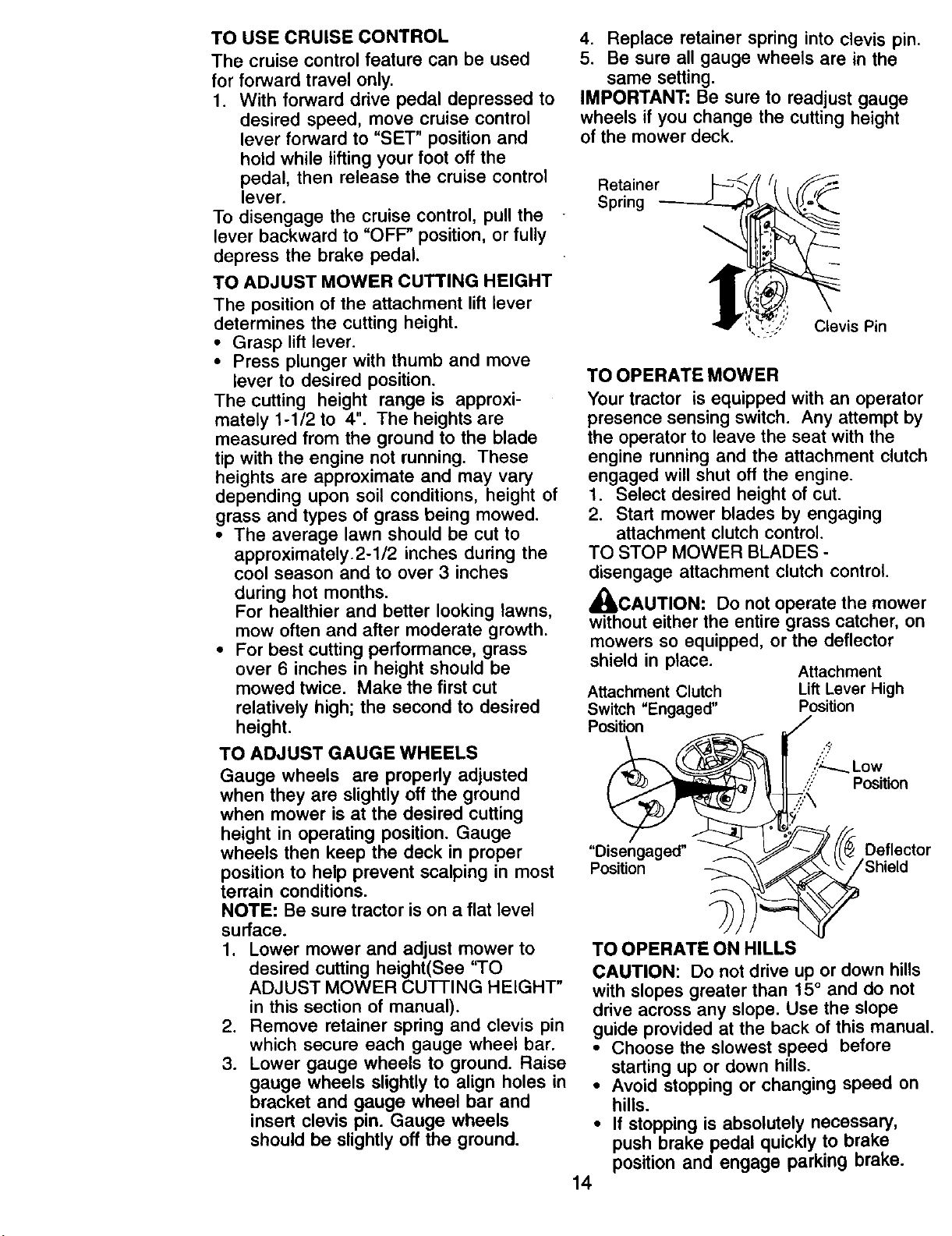
4. Replace retainer spring into clevis pin.
5. Be sure all gauge wheels are in the
same setting.
IMPORTANT: Be sure to readjust gauge
wheels if you change the cutting height
of the mower deck.
Retainer
Spring
Clevis Pin
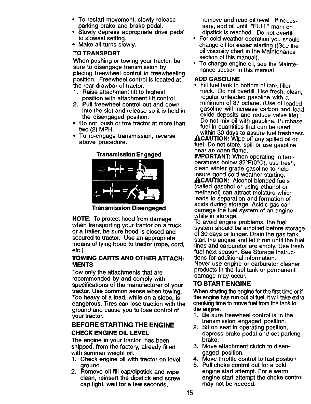
TO OPERATE MOWER
Your tractor is equipped with an operator
presence sensing switch. Any attempt by
the operator to leave the seat with the
engine running and the attachment clutch
engaged will shut off the engine.
1. Select desired height of cut.
2. Start mower blades by engaging
attachment clutch control,
TO STOP MOWER BLADES -
disengage attachment clutch control.
_ICAUTION: Do not operate the mower
without either the entire grass catcher, on
mowers so equipped, or the deflector
shield in place.
Attachment Clutch
Switch "Engaged"
Position
Attachment
Lift Lever High
Position
/
,:(_,._.,Low
,':" Position
r,
_/_ Deflector
Shield
TO OPERATE ON HILLS
CAUTION: Do not drive up or down hills
with slopes greater than 15° and do not
drive across any slope. Use the slope
guide provided at the back of this manual.
• Choose the slowest speed before
starting up or down hills.
• Avoid stopping or changing speed on
hills.
• If stopping is absolutely necessary,
push brake pedal quickly to brake
position and engage parking brake.
14
• To restart movement,slowly release
parking brake and brake pedal.
• Slowly depress appropriate drive pedal
to slowest setting.
• Make all turns slowly.
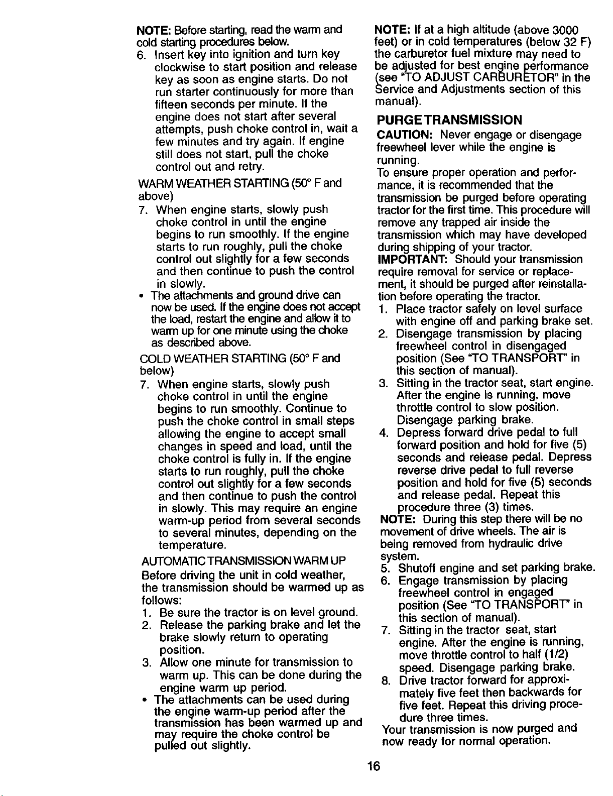
TO TRANSPORT
When pushing or towing your tractor, be
sure to disengage transmission by
placing freewheel control in freewheeling
position. Freewheel control is located at
the rear drawbar of tractor.
1. Raise attachment lift to highest
position with attachment lift control.
2. Pull freewheel control out and down
into the slot and release so it is held in
the disengaged position.
• Do not push or tow tractor at more than
two (2) MPH.
• To re-engage transmission, reverse
above procedure.
Transmission Engaged
Transmission Disengaged
NOTE: To protect hood from damage
when transporting your tractor on a truck
or a trailer, be sure hood is closed and
secured to tractor. Use an appropriate
means of tying hood to tractor (rope, cord,
etc.).
TOWING CARTS AND OTHER ATTACH-
MENTS
Tow only the attachments that are
recommended by and comply with
specifications of the manufacturer of your
tractor. Use common sense when towing.
Too heavy of a load, while on a slope, is
dangerous. Tires can lose traction with the
ground and cause you to lose control of
your tractor.
BEFORE STARTING THE ENGINE
CHECK ENGINE OIL LEVEL
The engine in your tractor has been
shipped, from the factory, already filled
with summer weight oil.
1. Check engine oil with tractor on level
ground.
2. Remove oil fill cap/dipstick and wipe
clean, reinsert the dipstick and screw
cap tight, wait for a few seconds,
15
remove and read oil level. If neces-
sary, add oil until "FULL" mark on
dipstick is reached. Do not overfill.
For cold weather operation you should
change oil for easier starting ((See the
oil viscosity chart in the Maintenance
section of this manual).
To change engine oil, see the Mainte-
nance section in this manual.
ADD GASOLINE
• Fill fuel tank to bottom of tank filler
neck. Do not overfill. Use fresh, clean,
regular unleaded gasoline with a
minimum of 87 octane. (Use of leaded
gasoline will increase carbon and lead
oxide deposits and reduce valve life).
Do not mix oil with gasoline. Purchase
fuel in quantities that can be used
within 30 days to assure fuel freshness.
_CAUTION: Wipe off any spilled oil or
fuel. Do not store, spill or use gasoline
near an open flame.
IMPORTANT: When operating in tem-
peratures below 32°F(0°C), use fresh,
clean winter grade gasoline to help
insure good cold weather starting.
• ILCAUTION: Alcohol blended fuels
(called gasohol or using ethanol or
methanol) can attract moisture which
leads to separation and formation of
acids during storage. Acidic gas can
damage the fuel system of an engine
while in storage.
To avoid engine problems, the fuel
system should be emptied before storage
of 30 days or longer. Drain the gas tank,
start the engine and let it run until the fuel
lines and carburetor are empty. Use fresh
fuel next season. See Storage Instruc-
tions for additional information.
Never use engine or carburetor cleaner
products in the fuel tank or permanent
damage may occur.
TO START ENGINE
When startingthe engine for the first time or if
the engine has runout of fuel, itwill take extra
crankin_time to move fuel from the tank to
the engine.
1. Be sure freewheel control is in the
transmission engaged position.
2. Sit on seat in operating position,
depress brake pedal and set parking
brake.
3. Move attachment clutch to disen-
gaged position.
4. Move throttle control to fast position
5. Pull choke control out for a cold
engine start attempt. For a warm
engine start attempt the choke control
may not be needed.
NOTE:Beforestarting,readthewarm and
cold starting procedures below.
6. Insert key into ignition and turn key
clockwise to start position and release
key as soon as engine starts. Do not
run starter continuously for more than
fifteen seconds per minute. If the
engine does not start after several
attempts, push choke control in, wait a
few minutes and try again. If engine
still does not start, pull the choke
control out and retry.
WARM WEATHER STARTING (50° F and
above)
7. When engine starts, slowly push
choke control in until the engine
begins to run smoothly. If the engine
starts to run roughly, pull the choke
control out slightly for a few seconds
and then continue to push the control
in slowly.
• The attachments and ground drive can
now be used. If the engine does not accept
the load, restart the engine and allow it to
warm up for one minute using the choke
as described above.
COLD WEATHER STARTING (500 F and
below)
7. When engine starts, slowly push
choke control in until the engine
begins to run smoothly. Continue to
push the choke control in small steps
allowing the engine to accept small
changes in speed and load, until the
choke control is fully in. If the engine
starts to run roughly, pull the choke
control out slightly for a few seconds
and then continue to push the control
in slowly. This may require an engine
warm-up period from several seconds
to several minutes, depending on the
temperature.
AUTOMATIC TRANSMISSION WARM UP
Before driving the unit in cold weather,
the transmission should be warmed up as
follows:
1. Be sure the tractor is on level ground.
2. Release the parking brake and let the
brake slowly return to operating
position.
3. Allow one minute for transmission to
warm up. This can be done during the
engine warm up period.
• The attachments can be used during
the engine warm-up period after the
transmission has been warmed up and
may require the choke control be
pulled out slightly.
NOTE: If at a high altitude (above 3000
feet) or in cold temperatures (below 32 F)
the carburetor fuel mixture may need to
be adjusted for best engine performance
(see "TO ADJUST CARBURETOR in the
Service and Adjustments section of this
manual).
PURGE TRANSMISSION
CAUTION: Never engage or disengage
freewheel lever while the engine is
running.
To ensure proper operation and perfor-
mance, it is recommended that the
transmission be purged before operating
tractor for the first time. This procedure will
remove any trapped air inside the
transmission which may have developed
during shipping of your tractor.
IMPORTANT: Should your transmission
require removal for service or replace-
ment, it should be purged after reinstalla-
tion before operating the tractor.
1. Place tractor safely on level surface
with engine off and parking brake set.
2. Disengage transmission by placing
freewheel control in disengaged
position (See "TO TRANSPORT" in
this section of manual).
3. Sitting in the tractor seat, start engine.
After the engine is running, move
throttle control to slow position.
Disengage parking brake.
4. Depress forward drive pedal to full
forward position and hold for five (5)
seconds and release pedal. Depress
reverse drive pedal to full reverse
position and hold for five (5) seconds
and release pedal. Repeat this
procedure three (3) times.
NOTE: During this step there will be no
movement of drive wheels. The air is
being removed from hydraulic drive
system.
5. Shutoff engine and set parking brake.
6. Engage transmission by placing
freewheel control in engaged
position (See "TO TRANSPORT" in
this section of manual).
7. Sitting in the tractor seat, start
engine. After the engine is running,
move throttle control to half (1/2)
speed. Disengage parking brake.
8. Drive tractor forward for approxi-
mately five feet then backwards for
five feet. Repeat this driving proce-
dure three times.
Your transmission is now purged and
now ready for normal operation.
16
MOWING TIPS
• Mower should be properly leveled for
best mowing performance. See "TO
LEVEL MOWER HOUSING" in the
Service and Adjustments section of
this manual.
• The left hand side of mower should be
used for trimming.
• Drive so that clippings are discharged
onto the area that has already been
cut. Have the cut area to the right of
the tractor. This will result in a more
even distribution of clippings and more
uniform cutting.
• When mowing large areas, start by
tuming to the right so that clippings will
discharge away f.rem shrubs, fences,
driveways, etc. After one or two
rounds, mow in the opposite direction
making left hand turns until finished.
c----
• If grass is extremely tall, it should be
mowed twice to reduce load and
possible fire hazard from dried clip-
pings. Make first cut relatively high; the
second to the desired height.
• Do not mow grass when it is wet. Wet
grass will plug mower and leave
undesirable clumps. Allow grass to dry
before mowing.
• Always operate engine at full throttle
when mowing to assure better mowing
performance and proper discharge of
material. Regulate ground speed by
selecting a low enough gear to give the
mower cutting performance as well as
the quality of cut desired.
• When operating attachments, select a
ground speed that will suit the terrain
and give best performance of the
attachment being used.
MULCHING MOWING TIPS
IMPORTANT: For best performance,
keep mower housing free of built-up
grass and trash. Clean after each use.
• The special mulching blade will recut
the grass clippings many times and
reduce them in size so that as they fall
onto the lawn they will disperse into tl_
grass and not be noticed. Also, the
mulched grass will biodegrade quickl!
to provide nutrients for the lawn.
Always mulch with your highest engin
(blade) speed as this will provide the
best recutting action of the blades.
• Avoid cutting your lawn when it is wet.
Wet grass tends to form clumps and
interferes with the mulching action.
The best time to mow your lawn is the
early afternoon. At this time the grass
has dried and the newly cut area wit1
not be exposed to the direct sun.
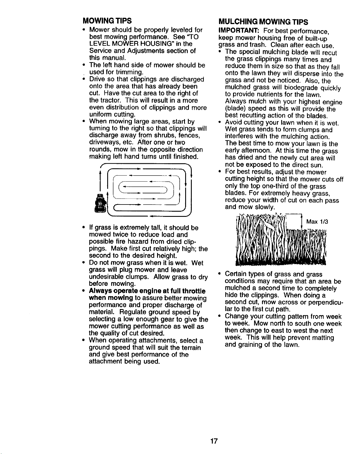
• For best results, adjust the mower
cutting height so that the mower cuts o
only the top one-third of the grass
blades. For extremely heavy grass,
reduce your width of cut on each pass
and mow slowly.
Max 1/3
• Certain types of grass and grass
conditions may require that an area b_
mulched a second time to completely
hide the clippings. When doing a
second cut, mow across or perpendicL
lar to the first cut path.
• Change your cutting pattern from weel
to week. Mow north to south one weel
then change to east to west the next
week. This will help prevent matting
and graining of the lawn.
17
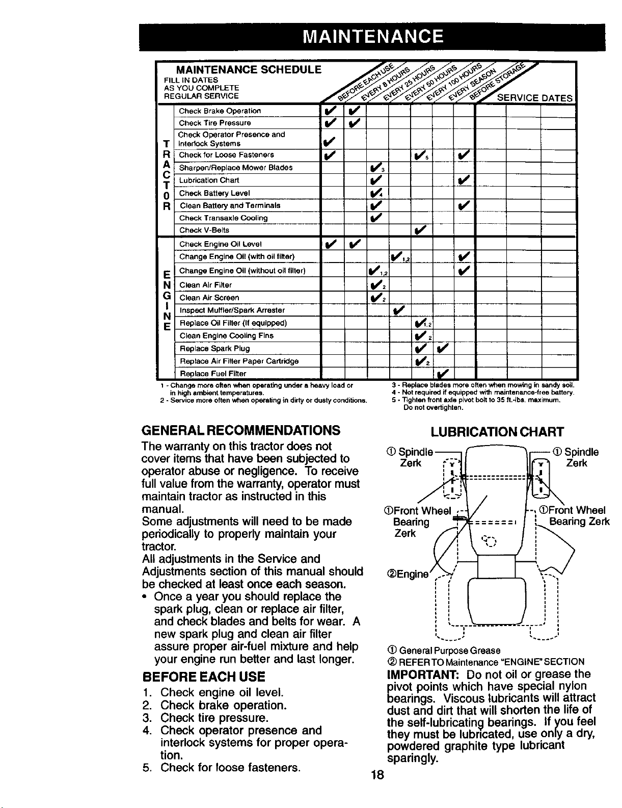
FILL IN DATES
REdo...SERV,CE DATES
Check Operator Presence and
T Interlock Systems I_
R Check for Loose Fasteners I_ V's V _
A Sharpen/Replace Mower Blades V__
T Lubrication Chart _1
0 Check Battery Level
R Clean Battery and Terminals jI##
Check Transaxlo Cooling
Check V-Beits V'
Check Engine Oil Level I_ V'
Change Engine Oil (with OII filter) V_I_
E Change Engine Oil (without oil filter) Iit_l _. _1_
N CleanAlrFilter _1;
G Clean Air Screen
i_ Muffler/Spark Arrester I_
Inspect
E Replace Oil Filter (If equipped) 1_1.2
Clean Engine Cooling Fins Iff'z
Replace Spark Plug _2 I#1
Replace Air Filler Paper Cartridge
Replace Fuel Filter !1_
1 - Change more often when operating under a heavy load or
in high ambient temperatures.
2 - Service more often when operating in dirty or dusty conditions.
3 - Replace blades more often when mowing in sandy soil
4 - Not required if equipped with maintenance-free battery.
5 - Tighten front axle pivot bolt to 35 ll.-Ibs, maximum.
Do not overtighten.
GENERALRECOMMENDATIONS
The warranty on this tractor does not
cover items that have been subjected to
operator abuse or negligence. To receive
full value from the warranty, operator must
maintain tractor as instructed in this
manual.
Some adjustments will need to be made
periodically to properly maintain your
tractor.
All adjustments in the Service and
Adjustments section of this manual should
be checked at least once each season.
• Once a year you should replace the
spark plug, clean or replace air filter,
and check blades and belts for wear. A
new spark plug and clean air filter
assure proper air-fuel mixture and help
your engine run better and last longer.
BEFOREEACH USE
1. Check engine oil level.
2. Check brake operation.
3. Check tire pressure.
4. Check operator presence and
interlock systems for proper opera-
tion.
5. Check for loose fasteners.
LUBRICATION CHART
(_ Spindle
Zer.
(gFront Wheel ,-
Beadng
Zerk _
_)Engine' ,.-%)',,'
i
i.--
(D Spindle
Zerk
-, OFront Wheel
=:====, ! BeadngZerk
r,
(_ General Purpose Grease
(_)REFERTO Maintenance =ENGINE" SECTION
IMPORTANT: Do not oil or grease the
pivot points which have special nylon
bearings. Viscous lubricants will attract
dust and dirt that will shorten the life of
the self-lubricatin 9 bearings, if you feel
they must be lubncated, use only a dry,
powdered graphite type lubricant
sparingly.
18
TRACTOR
Always observe safety rules when
performing any maintenance.
BRAKE OPERATION
If tractor requires more than six (6) feet
stopping distance at high speed in
highest gear, then brake must be ad-
justed. (See "TO ADJUST BRAKE" in the
Service and Adjustments section of this
manual).
TIRES
• Maintain proper air pressure in all tires
(See "PRODUCT SPECIFICATIONS"
section of this manual).
• Keep tires free of gasoline, oil, or insect
control chemicals which can harm
rubber.
• Avoid stumps, stones, deep ruts, sharp
objects and other hazards that may
cause tire damage.
NOTE: To seal tire punctures and prevent
flat tires due to slow leaks, tire sealant
may be purchased from your local parts
dealer. Tire sealant also prevents tire dry
rot and corrosion.
OPERATOR PRESENCE SYSTEM
Be sure operator presence and interlock
systems are working properly, if your
tractor does not function as described,
repair the problem immediately.
• The engine should not start unless the
brake pedal is fully depressed and
attachement clutch control is in the
disengaged position.
• When the engine is running, any
attempt by the operator to leave the
seat without first setting the parking
brake should shut off the engine.
• When the engine is running and the
attachment clutch is engaged, any
attempt by the operator to leave the
seat should shut off the engine.
• The attachment clutch should never
operate unless the operator is in the
seat.
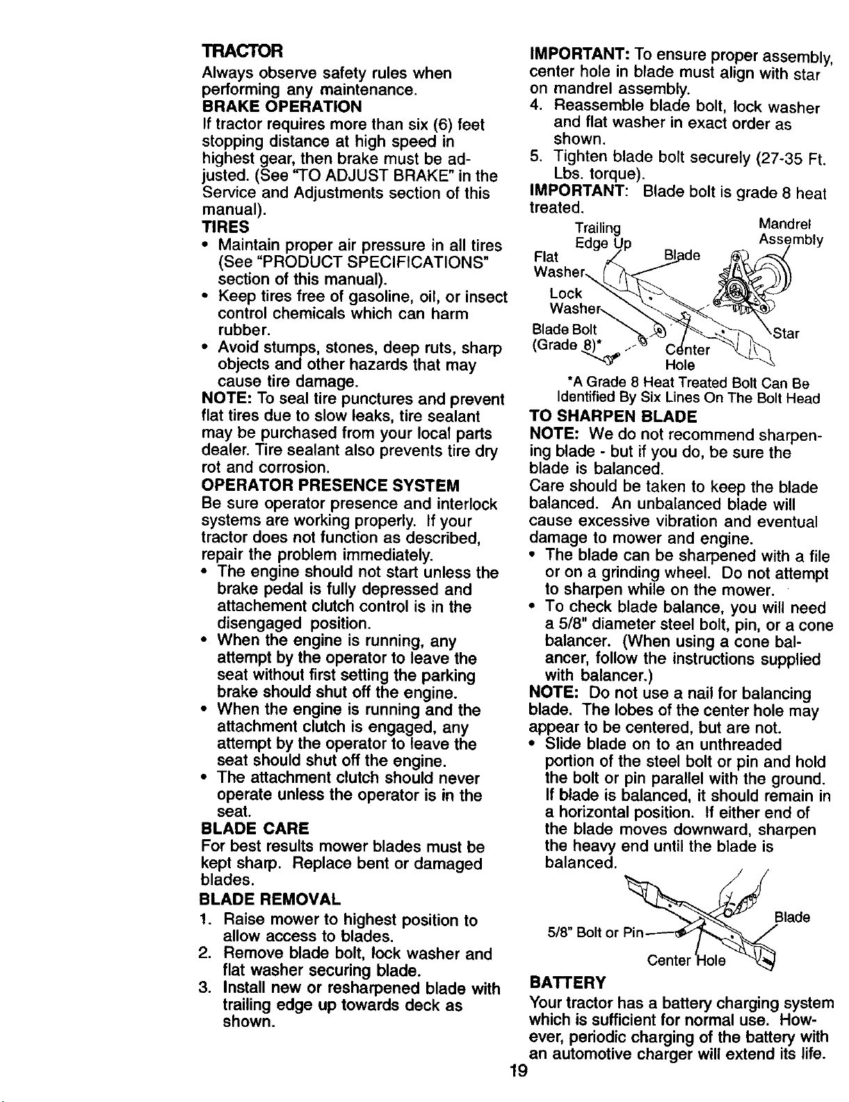
BLADE CARE
For best results mower blades must be
kept sharp. Replace bent or damaged
blades.
BLADE REMOVAL
I. Raise mower to highest position to
allow access to blades.
2. Remove blade bolt, lock washer and
flat washer securing blade.
3. Install new or resharpened blade with
trailing edge up towards deck as
shown.
IMPORTANT: To ensure proper assembly,
center hole in blade must align with star
on mandrel assembly.
4. Reassemble blade bolt, lock washer
and flat washer in exact order as
shown.
5. Tighten blade bolt securely (27-35 Ft.
Lbs. torque).
IMPORTANT: Blade bolt is grade 8 heat
treated.
Trailing Mandrel
Edge Assembly
Flat
Lock
Washer,.....
Blade Bolt
(Grade 8)_f ..
Hole
*A Grade 8 Heat Treated Bolt Can Be
Identified By Six Lines On The Bolt Head
TO SHARPEN BLADE
NOTE: We do not recommend sharpen-
ing blade - but if you do, be sure the
blade is balanced.
Care should be taken to keep the blade
balanced. An unbalanced blade will
cause excessive vibration and eventual
damage to mower and engine.
• The blade can be sharpened with a file
or on a grinding wheel. Do not attempt
to sharpen while on the mower.
• To check blade balance, you will need
a 5/8" diameter steel bolt, pin, or a cone
balancer. (When using a cone bal-
ancer, follow the instructions supplied
with balancer.)
NOTE: Do not use a nail for balancing
blade. The lobes of the center hole may
appear to be centered, but are not.
• Slide blade on to an unthreaded
portion of the steel bolt or pin and hold
the bolt or pin parallel with the ground.
If blade is balanced, it should remain in
a horizontal position. If either end of
the blade moves downward, sharpen
the heavy end until the blade is
balanced.
Blade
5/8"
Center
BATTERY
Your tractor has a battery charging system
which is sufficient for normal use. How-
ever, periodic charging of the battery with
an automotive charger will extend its life.
19
• Keep battery and terminals clean.
• Keep battery bolts tight.
• Keep small vent holes open.
• Recharge at 6-10 amperes for 1 hour.
NOTE: The original equipment battery on
your tractor is maintenance free. Do not
attempt to open or remove caps or covers.
Adding or checking level of electrolyte is
not necessary.
TO CLEAN BATTERY AND TERMINALS
Corrosion and dirt on the battery and
terminals can cause the battery to "leak"
power.
1. Remove terminal guard.
2. Disconnect BLACK battery cable first
then RED battery cable and remove
battery from tractor.
3. Rinse the battery with plain water and
dry.
4. Clean terminals and battery cable
ends with wire brush until bright.
5. Coat terminals with grease or petro-
leum jelly.
6. Reinstall battery (See "REPLACING
BATTERY" in the SERVICE AND
ADJUSTMENTS section of this
manual).
TRANSAXLE COOLING
The transmission fan and cooling fins
should be kept clean to assure proper
cooling.
Do not attempt to clean fan or transmission
while engine is running or while the
transmission is hot. To prevent possible
damage to seals, do not use high pressure
water or steam to clean transaxle.
• Inspect cooling fan to be sure fan blades
are intact and clean.
• Inspect cooling fins for dirt, grass
clippings and other materials. To
prevent damage to seals, do not use
compressed air or high pressure sprayer
to clean cooling fins.
TRANSAXLE PUMP FLUID
The transaxle was sealed at the factory
and fluid maintenance is not required for
the life of the transaxle. Should the
transaxle ever leak or require servicing,
contact a Sears or other qualified service
center.
V-BELTS
Check V-belts for deterioration and wear
after 100 hours of operation and replace if
necessary. The belts are not adjustable.
Replace belts if they begin to slip from
wear.
ENGINE
LUBRICATION
Only use high quality detergent oil rated
with API service classification SF-SJ.
Select the oil's SAE viscosity grade
according to your expected operating
temperature.
NOTE: Although multi-viscosity oils
(5W30, 10W30 etc.) improve starting in
cold weather, these multi-viscosity oils will
result in increased oil consumption when
used above 32°F. Check your engine oil
level more frequently to avoid possible
engine damage from running low on oil.
Change the oil after every 50 hours of
operation or at least once a year ifthe
tractor is not used for 50 hours in one year.
Check the crankcase oil level before
starting the engine and after each eight (8)
hours of operation. Tighten oil fill cap/
dipstick securely each time you check the
oil level.
TO CHANGE ENGINE OIL
Determine temperature range expected
before oil change. All oil must meet API
service classification SF-SJ.
• Be sure tractor is on level surface.
• Oil will drain more freely when warm.
• Catch oil in a suitable container.
1. Remove oil fill cap/dipstick. Be careful
not to allow dirt to enter the engine
when changing oil.
2. Remove yellow cap from end of drain
valve and install the drain tube onto
the fitting.
Oil DrainValve
Closed_ A
and
Locked |
Position _
Yellow Cap _"
__ Drain
. _Tube
3. Unlock drain valve by pushing inward
slightly and turning counterclockwise.
4. To open, pull out on the drain valve.
5. After oil has drained completely, close
and lock the drain valve by pushing
inward and turning clockwise until the
pin is in the locked position as shown.
6. Remove the drain tube and replace
the cap onto the end of the drain
20 valve.
.
.
Refill engine with oil through oil fill
dipstick tube. Pour slowly. Do not
overfill. For approximate capacity see
=PRODUCT SPECIFICATIONS"
section of this manual.
Use gauge on oil fill cap/dipstick for
checking level. For accurate reading,
tighten dipstick cap securely onto the
tube before removing dipstick. Keep
oil at "FULL" line on dipstick. Tighten
cap onto the tube securely when
finished.
ENGINE OIL FILTER
Replace the engine oil filter every season
or every other oil change if the tractor is
used more than 100 hours in one year.
AIR FILTER
Your engine will not run properly using a
dirty air filter. Clean the foam pre-cleaner
after every 25 hours of operation or every
season. Service paper cartridge every
100 hours of operation or every season,
whichever occurs first.
Service air cleaner more often under
dusty conditions.
1. Remove knobs and cover.
TO SERVICE PRE-CLEANER
2. Wash it in liquid detergent and water.
3. Squeeze it dry in a clean cloth.
4. Saturate it in engine oil. Wrap it in
clean, absorbent cloth and squeeze to
remove excess oil.
NOTE; If very dirty or damaged, replace
pre-cleaner.
TO SERVICE CARTRIDGE
1. Clean cartridge by tapping gently on
flat surface. If very dirty or damaged,
replace cartridge.
2. Reinstall precleaner cartridge, cover
and secure with knobs.
IMPORTANT; Petroleum solvents, such
as kerosene, are not to be used to clean
the cartridge. They may cause deteriora-
tion of the cartridge. Do not oil cartridge.
Do not use pressurized air to clean or dry
cartridge.
CLEAN AIR SCREEN
Air screen must be kept free of dirt and
chaff to prevent engine damage from
overheating. Clean with a wire brush or
compressed air to remove dirt and
stubborn dried gum fibers.
CLEAN AIR INTAKE/COOLING AREAS
To insure proper cooling, make sure the
grass screen, cooling fins, and other
external surfaces of the engine are kept
clean at all times.
Every 100 hours of operation (more often
under extremely dusty, dirty conditions),
remove the blower housing and other
cooling shrouds. Clean the cooling fins
and external surfaces as necessary. Make
sure the cooling shrouds are reinstalled.
NOTE: Operating the engine with a
blocked grass screen, dirty or plugged
cooling fins, and/or cooling shrouds
removed will cause engine damage due
to overheating.
MUFFLER
Inspect and replace corroded muffler and
spark arrester (if equipped) as it could
create a fire hazard and/or damage.
SPARK PLUG(S)
Replace spark plug(s) at the beginning of
each mowing season or after every 100
hours of operation, whichever occurs first.
Spark plug type and gap setting are
shown in "PRODUCT SPECIFICATIONS"
section of this manual.
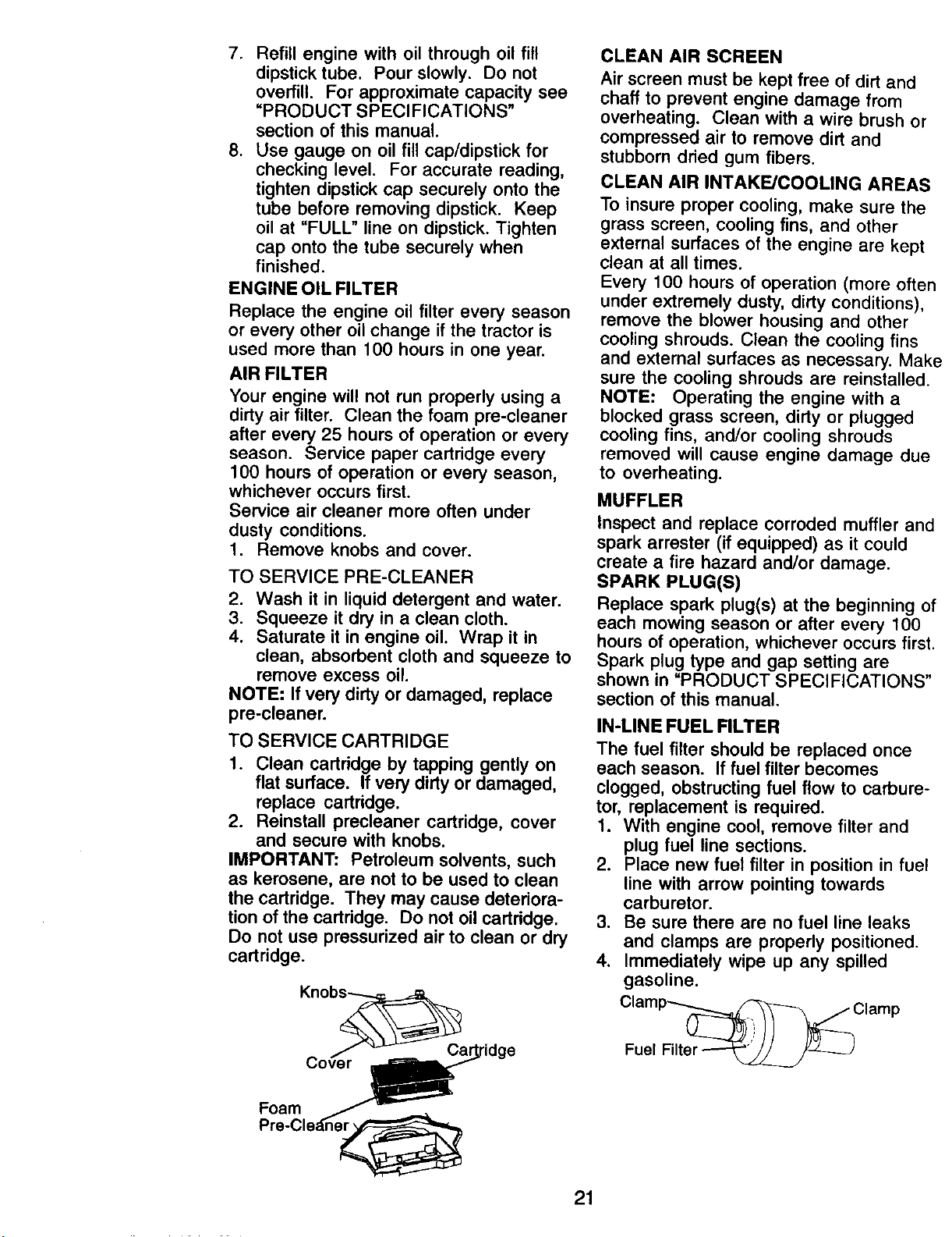
IN-LINE FUEL FILTER
The fuel filter should be replaced once
each season. If fuel filter becomes
clogged, obstructing fuel flow to carbure-
tor, replacement is required.
1. With engine cool, remove filter and
plug fuel line sections.
2. Place new fuel filter in position in fuel
line with arrow pointing towards
carburetor.
3. Be sure there are no fuel line leaks
and clamps are properly positioned.
4. Immediately wipe up any spilled
gasoline.
ClamP_clamp
Fuel Filter
Foam
21
CLEANING
• Clean engine, battery, seat, finish, etc.
of all foreign matter.
• Keep finished surfaces and wheels free
of all gasoline, oil, etc.
• Protect painted surfaces with automo-
tive type wax.
We do not recommend using a garden
hose to clean your tractor unless the
electrical system, muffler, air filter and
carburetor are covered to keep water out.
Water in engine can result in a shortened
engine life.
WARNING: TO AVOID SERIOUS INJURY, BEFORE PERFORMING ANY
SERVICE OR ADJUSTMENTS:
1. Depress brake pedal fully and set parking brake.
2. Place attachment clutch in "DISENGAGED" position.
3. Turn ignition key to "STOP" and remove key.
4. Make sure the blades and all moving parts have completely stopped.
5. Disconnect spark plug wire from spark plug and place wire where it cannot
come in contact with plug.
TRACTOR
TO REMOVE MOWER
1. Place attachment clutch in "DISEN-
GAGED" position.
2. If equipped, turn height adjustment
knob to lowest setting.
3. Lower mower to its lowest position,
4, Remove retainer spring holding anti-
sway bar to chassis bracket and
disengage anti-sway bar from bracket.
5. Remove four retainer springs from
front plate assembly and remove
plate.
6. Remove retainer springs from
suspension arms at deck and disen-
gage arms from deck.
7. Raise attachment lift to its highest
position.
8. Slide mower forward and remove belt
from electric clutch pulley.
9. Slide mower out from under right side
of tractor.
Chassis
Bracket
Retainer
Spring
TO INSTALL MOWER
Be sure tractor is on level surface and
mower suspension arms are raised with
attachment lift control. Engage parking
brake.
1. Swing anti-sway bar to left side of
mower deck.
2. Slide mower under tractor with
deflector shield to right side of tractor.
IMPORTANT: Check belt for proper
routing in all mower pulley grooves.
3. If equipped, turn height adjustment
knob counterclockwise until it stops.
4. Lower mower linkage with attachment
lift control.
5. Install belt into electric clutch pulley
groove.
6. Place the suspension arms on
outward pointing deck pins. Retain
with double loop retainer spring with
loops up as shown.
Front Mower
Bracket
Clutch Pulley
Front Plate
Assembly
Single Loop
Retainer Springs
Bar
Double Loop
Retainer Springs
USE PLIERS FOR
RETAINER SPRINGS
Suspension Arms Double Loop
Retainer Springs (Outward
pointingdeck pins)
22
ed Pins
Front Mower
Bracket
Deflector Shield
7. Install front plate assembly to tractor
suspension brackets and retain with
single loop retainer springs as shown.
8. Position front plate assembly between
front mower brackets. Raise deck and
plate assembly to align holes and
insert flanged pins. Secure pins with
double loop retainer springs between
the plate and mower brackets,
NOTE: To assist in locating hole in
flanged pin, the hole in pin is inline with
notch on head of pin. If necessary, move
mower side-to-side to give space
between plate and mower brackets.
IMPORTANT: Check belt for proper
routing in all mower pulley grooves.
9. Connect anti-sway bar to chassis
bracket under left footrest and retain
with double loop retainer spring.
10. If equipped, turn height adjustment
knob clockwise to remove slack from
mower suspension.
11. Raise deck to highest position.
TO LEVEL MOWER HOUSING
Adjust the mower while tractor is parked
on level ground or driveway. Make sure
tires are properly inflated (See "PROD-
UCT SPECIFICATIONS" section of this
manual). If tires are over or underinflated,
you wilt not properly adjust your mower.
SIDE-TO-SIDE ADJUSTMENT WITH
BUBBLE LEVEL
NOTE: If necessary, check side-to-side
surface below tractor for levelness with a
long board and the bubble level.
• Using the lift lever, place mower in
position where no part of the mower,
including gauge wheels, is touching the
ground.
• From left side of tractor, find the level
decal on top of mower and place
bubble level on decal as indicated.
• Mower is level side-to-side when
bubble is between the two lines in the
bubble level.
• If adjustment is necessary, under left
hand footrest, turn lift link adjustment
nut (above yellow cap) in appropriate
direction to bring bubble between the
lines in the bubble level.
• Remove bubble level from mower and
store in a safe place.
Bubble Between Bubble Level
Lines
Level Decal
Braket"_ LeftHand
_Adjustment
¥_llOW_ _ Nut
Cap
ALTERNATE SIDE-TO-SIDE
ADJUSTMENT METHOD
• Raise mower to its highest position.
• At the midpoint of both sides of mower,
measure height from bottom edge of
mower to ground. Distance "A" on
both sides of mower should be the
same or within 1/4" of each other.
• If adjustment is necessary, make
adjustment on one side of mower only.
• To raise one side of mower, tighten lift
link adjustment nut on that side.
• To lower one side of mower, loosen lift
link adjustment nut on that side.
NOTE: Each full turn of adjustment nut
will change mower height about 1/8".
• Recheck measurements after adjust-
ing.
Bottom Edge of Bottom Edge of
Mower to Ground Mower to Ground
Suspension
Arm
Lift Link
ustment
Nut
FRONT-TO-BACK ADJUSTMENT
IMPORTANT: Deck must be level side-to-
side. If the following front-to-back adjust-
. ment is necessary, be sure to adjust both
front links equally so mower will stay
level side-to-side.
To obtain the best cutting results, the
mower housing should be adjusted so
that the front is approximately 1/8" to 1/2"
lower than the rear when the mower is in
its highest position.
Check adjustment on right side of tractor.
Measure distance "D" directly in front of
and behind the mandrel at bottom edge of
mower housing as shown,
23
• Before making any necessary adjust-
ments, check that both front plate links
are equal in length.
• If links are not equal in length, adjust
one link to same length as other link.
• To lower front of mower loosen nut "E"
on both front links an equal number of
turns.
• When distance "D" is 1/8" to 1/2" lower
at front than rear, tighten nuts "F"
against trunnion on both front links.
• To raise front of mower, loosen nut "F"
from trunnion on both front links.
Tighten nut "E" on both front links an
equal number of turns. The two front
links must remain equal in length.
• When distance "D" is 1/8" to 1/2" lower
at front than rear, tighten nut "F" against
trunnion on both front links.
• Recheck side-to-side adjustment.
Measure distance "D" directly in front of
and behind the mandrel at bottom edge of
mower housing as shown.
• Before making any necessary adjust-
ments, check that both front links are
equal in length.
• If links are not equal in length, adjust
one link to same length as other link.
• To lower front of mower loosen nut "E"
on both front links an equal number of
turns.
• When distance "D" is 1/8" to 1/2" lower
at front than rear, tighten nuts "F"
against trunnion on both front links.
• To raise front of mower, loosen nut "F"
from trunnion on both front links.
Tighten nut "E" on both front links an
equal number of turns. The two front
links must remain equal in length.
• When distance "D" is 1/8" to 1/2" lower
at front than rear, tighten nut "F" against
trunnion on both front links.
• Recheck side-to-side adjustment.
Mandrel
BOTH FRONT PLATE LINKS MUST BE
EQUAL IN LENGTH
Nut "______!_ Nut "E"
Links
TO REPLACE MOWER BLADE DRIVE
BELT
The mower blade drive belt may be
replaced without tools. Park the tractor
on level surface. Engage parking brake.
BELT REMOVAL -
1, Remove mower from tractor (See "TO
REMOVE MOWER" in this section of
manual).
2. Work belt off both mandrel pulleys
and idler pulleys.
3. Pull belt away from mower.
BELT INSTALLATION -
1. Work belt around both mandrel
pulleys and idler pulleys
2. Make sure belt is in all pulley grooves
and inside all belt guides.
3. Install mower (See "To Install Mower"
in this section of this manual).
Mandrel
Idler
\
Mandrel
Pulley
24
TO ADJUST BRAKE
Your tractor is equipped with an adjustable
brake system which is mounted on the
side of the transaxle.
Iftractor requires more than six (6) feet
stopping distance at high speed in highest
gear on a level dry concrete or paved
surface, then brake must be adjusted.
1. Depress clutch/brake pedal and
engage parking brake.
2. Measure distance between brake
operating arm and nut "A" on brake
rod.
3. If distance is other than 1-3/4", loosen
jam nut and turn nut "A" until distance
becomes 1-3/4". Retighten jam nut
against nut "A".
4. Road test tractor for proper stopping
distance as stated above. Readjust if
necessary. If stopping distance is still
greater than six (6) feet in highest
gear, further maintenance is neces-
sary. Contact a Sears or other
qualified service center.
With parking brake "Engaged"
Nut
Nut
Operating
Do not touch this nut. If further brake
adjustment is necessary contact a Sears or
other qualified service center.
TO REPLACE MOTION DRIVE BELT
Park the tractor on level surface. Engage
parking brake. For assistance, there is a
belt installation guide decal on bottom
side of left footrest.
BELT REMOVAL-
1. Remove mower (See 'q-O REMOVE
MOWER" in this section of manual).
NOTE: Observe entire motion drive belt
and position of all belt guides and
keepers.
2. Disconnect clutch wire harness.
3. Remove clutch Iocator.
4. Remove belt from stationary idler and
clutching idler.
5. Remove belt downward from engine
pulley and around electric clutch.
6. Pull belt slack toward rear of tractor.
Carefully remove belt upwards from
transmission input pulley and over
cooling fan blades.
7. Remove belt from center span keeper
and pull belt away from tractor.
BELT INSTALLATION -
1. Carefully work new belt down around
transmission cooling fan and onto the
input pulley.
2. Slide belt into the center span keeper.
3. Pull belt toward front of tractor and roll
belt around electric clutch and onto
engine pulley.
4. Install belt through stationary idler and
clutching idler.
5. Reinstall clutch Iocator and tighten nut
securely.
6. Reconnect clutch harness.
7. Make sure belt is in all pulley grooves
and inside all belt guides and keep-
ers.
8. Install mower (See "-I-O INSTALL
MOWER" in this section of manual).
Electric
Clutch
Clutching_
Idler
Stationary_
Idler
Center Span _
Keeper
Transmission _'_
Input Pulley
Clutch
-'_" Locator
o.utc.
Harness
25
TRANSMISSION REMOVAL/REPLACE-
MENT
Should your transmission require
removal for service or replacement, it
should be purged after reinstallation and
before operating the tractor. See =PURGE
TRANSMISSION" in the Operation
section of this manual.
TO ADJUST STEERING WHEEL ALIGN-
MENT
If steering wheel crossbars are not
horizontal (left to right) when wheels are
positioned straight forward, remove
steering wheel and reassemble with
crossbars horizontal. Tighten securely.
FRONT WHEEL TOE-IN/CAMBER
The front wheel toe-in and camber are
not adjustable on your tractor. If damage
has occurred to affect the front wheel toe-
in or camber, contact a Sears or other
qualified service center.
TO REMOVE WHEEL FOR REPAIRS
1. Block up axle securely.
2. Remove axle cover, retaining ring and
washers to allow wheel removal (rear
wheels have a square key - Do not
lose).
3. Repair tire and reassemble.
NOTE: On rear wheels only: align grooves
in rear wheel hub and axle. Insert square
key.
4. Replace washers and snap retaining
ring securely in axle groove.
5. Replace axle cover.
NOTE: To seal tire punctures and prevent
flat tires due to slow leaks, purchase and
use tire sealant from Sears. Tire sealant
also prevents tire dry rot and corrosion.
Washers
Retaining
Ring
Axle
Cover
I
Square Key
(Rear Wheel Only)
TO START ENGINE WITH A WEAK
BATTERY
4uLWARNING: Lead-acid batteries generate
explosive gases. Keep sparks, flame and
smoking materials away from batteries.
Always wear eye protection when around
batteries.
Ifyour battery istoo weak to startthe engine, it
should be recharged. (See "BATTERY" in the
MAINTENANCE section ofthis manual).
If"jumper cables" are used for emergency
starting,follow this procedure:
IMPORTANT: Your tractorisequippedwith a
12 volt system.The other vehicle must also be
a 12 voltsystem. Do not useyour tractor
batteryto start other vehicles.
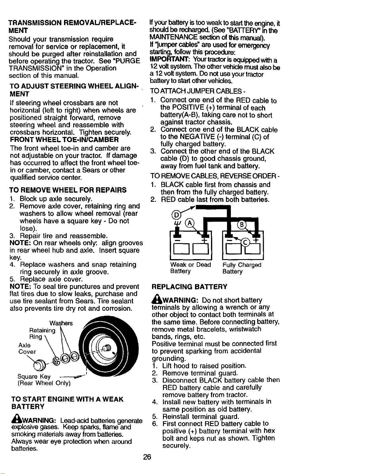
TO A'I-FACH JUMPER CABLES -
1. Connect one end of the RED cable to
the POSITIVE (+) terminal of each
battery(A-B), taking care not to short
against tractor chassis.
2. Connect one end of the BLACK cable
to the NEGATIVE (-) terminal (C) of
fully charged battery.
3. Connect the other end of the BLACK
cable (D) to good chassis ground,
away from fuel tank and battery.
TO REMOVE CABLES, REVERSE ORDER -
1. BLACK cable first from chassis and
then from the fully charged battery.
2. RED cable last from both batteries.
Weak or Dead Fully Charged
Battery Battery
REPLACING BATTERY
A
_WARNING: Do not short battery
terminals by allowing a wrench or any
other object to contact both terminals at
the same time. Before connecting battery,
remove metal bracelets, wristwatch
bands, rings, etc.
Positive terminal must be connected first
to prevent sparking from accidental
grounding.
1. Lift hood to raised position.
2. Remove terminal guard.
3. Disconnect BLACK battery cable then
RED battery cable and carefully
remove battery from tractor.
4. Install new battery with terminals in
same position as old battery.
5. Reinstall terminal guard.
6. First connect RED battery cable to
positive (+) battery terminal with hex
bolt and keps nut as shown. Tighten
securely.
26
7. Connect BLACK grounding cable to
negative (-) battery terminal with
remaining hex bolt and keps nut.
Tighten securely
8. Close terminal access doom.
9. Close hood.
Hex Bolt
Keps Nut
Terminal
Door
Positive
":" Cable
Guard
,Negative
(Black)
Cable
TO REPLACE HEADLIGHT LAMP
,_ CAUTION: When lit, the halogen
lamps get extremely hot. Hold lamp
assembly by the holder and do not touch
the bulb.
1. Raise hood.
2. Disconnect harness from lamp
assembly.
3. Rotate counterclockwise and pull
lamp assembly out of the hole in the
backside of the grill.
4. Insert new lamp assembly and rotate
clockwise to lock.
5. Reconnect harness to lamp
assembly.
6. Close hood.
INTERLOCKS AND RELAYS
Loose or damaged wiring may cause your
tractor to run poorly, stop running, or
prevent it from starting.
• Check wiring. See electrical wiring
diagram in the Repair Parts section.
TO REPLACE FUSE
Replace with 20 amp automotive-type
plug-in fuse. The fuse holder is located
behind the dash.
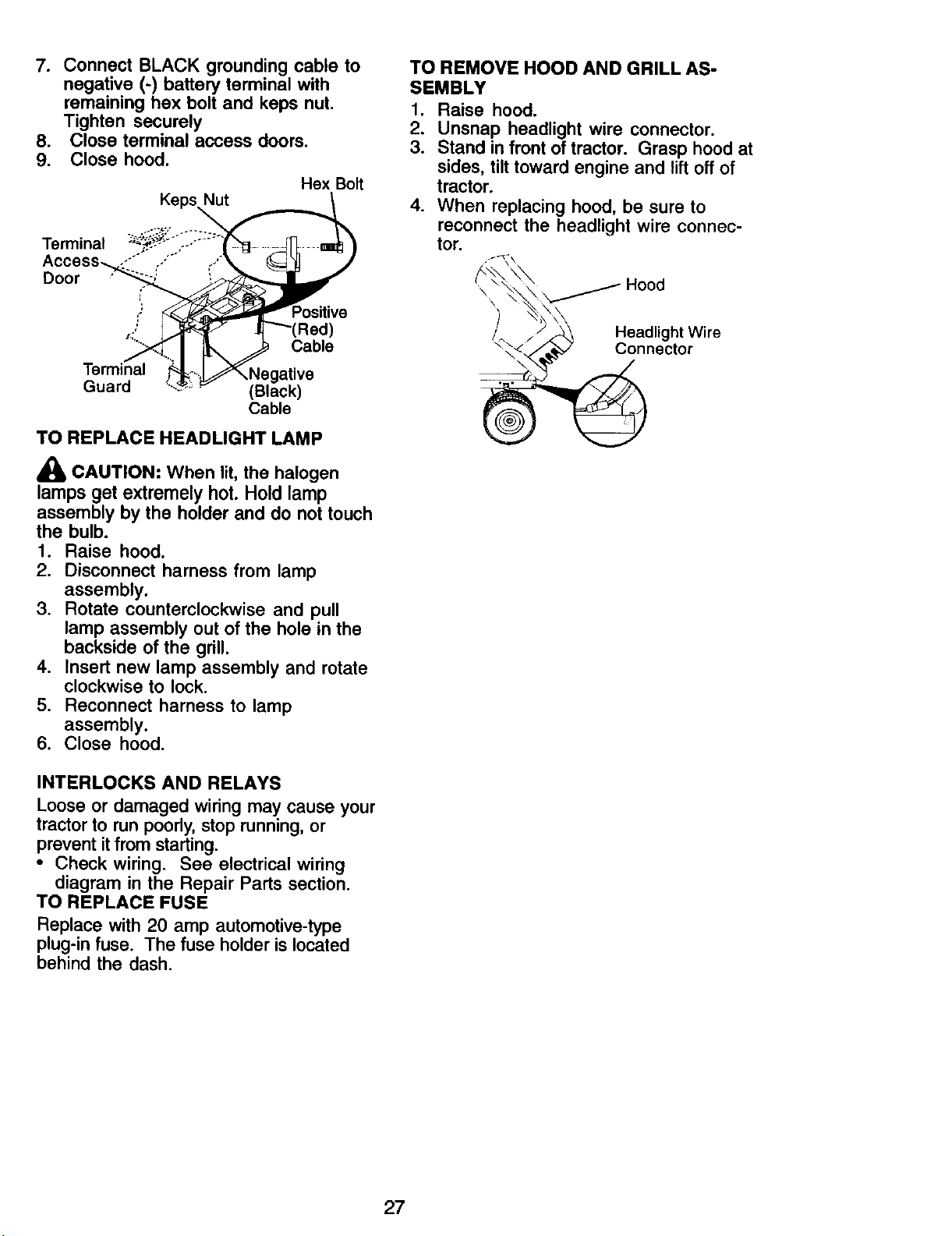
TO REMOVE HOOD AND GRILL AS-
SEMBLY
1. Raise hood.
2. Unsnap headlight wire connector.
3. Stand in front of tractor. Grasp hood at
sides, tilt toward engine and lift off of
tractor.
4. When replacing hood, be sure to
reconnect the headlight wire connec-
tor.
\
/_ Headlight Wire
\ _ Connector
27
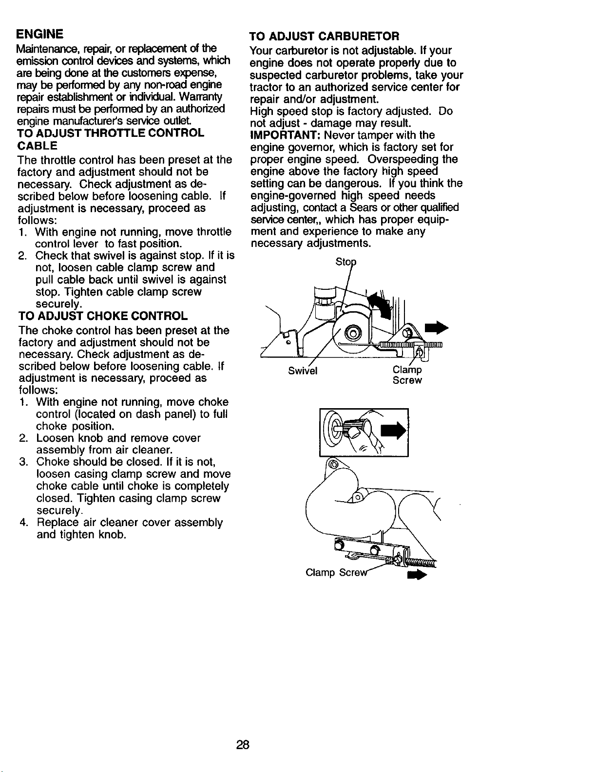
ENGINE
Maintenance, repair,or replacement of the
emission control devices and systems, which
are being done at the customers expense,
may be performed by any non-road engine
repair establishment or individual.Warranty
repairs must be performed by an authorized
engine manufacturer's service outlet.
TO ADJUST THROTTLE CONTROL
CABLE
The throttle control has been preset at the
factory and adjustment should not be
necessary. Check adjustment as de-
scribed below before loosening cable. If
adjustment is necessary, proceed as
follows:
1. With engine not running, move throttle
control lever to fast position.
2. Check that swivel is against stop. If it is
not, loosen cable clamp screw and
pull cable back until swivel is against
stop. Tighten cable clamp screw
securely.
TO ADJUST CHOKE CONTROL
The choke control has been preset at the
factory and adjustment should not be
necessary. Check adjustment as de-
scribed below before loosening cable. If
adjustment is necessary, proceed as
follows:
1. With engine not running, move choke
control (located on dash panel) to full
choke position.
2. Loosen knob and remove cover
assembly from air cleaner.
3. Choke should be closed. If it is not,
loosen casing clamp screw and move
choke cable until choke is completely
closed. Tighten casing clamp screw
securely.
4. Replace air cleaner cover assembly
and tighten knob.
TO ADJUST CARBURETOR
Your carburetor is not adjustable. If your
engine does not operate properly due to
suspected carburetor problems, take your
tractor to an authorized service center for
repair and/or adjustment.
High speed stop is factory adjusted. Do
not adjust - damage may result.
IMPORTANT: Never tamper with the
engine governor, which is factory set for
proper engine speed. Overspeeding the
engine above the factory high speed
setting can be dangerous, if you think the
engine-governed high speed needs
adjusting, contact a Sears or other qualified
service center,, which has proper equip-
ment and experience to make any
necessary adjustments.
/
Swivel
Screw
Claml
28
Immediately prepare your tractor for
storage at the end of the season or ifthe
tractor will not be used for 30 days or
more.
,_ CAUTION: Never store the tractor
with gasoline in the tank inside a building
where fumes may reach an open flame or
spark. Allow the engine to cool before
storing in any enclosure.
TRACTOR
Remove mower from tractor for winter
storage. When mower is to be stored for
a period of time, clean it thoroughly,
remove all dirt, grease, leaves, etc. Store
in a clean, dry area.
1. Clean entire tractor (See "CLEANING"
in the Maintenance section of this
manual).
2. Inspect and replace belts, if necessary
(See belt replacement instructions in
the Service and Adjustments section
of this manual).
3. Lubricate as shown in the Mainte-
nance section of this manual.
4. Be sure that all nuts, bolts and screws
are securely fastened. Inspect moving
parts for damage, breakage and wear.
Replace if necessary.
5. Touch up all rusted or chipped paint
surfaces; sand lightly before painting.
BATrERY
• Fully charge the battery for storage.
• After a period of time in storage, battery
may require recharging.
• To help prevent corrosion and power
leakage during long periods of storage,
battery cables should be disconnected
and battery cleaned thoroughly (see
"TO CLEAN BATTERY AND TERMI-
NALS" in the Maintenance section of
this manual).
• After cleaning, leave cables discon-
nected and place cables where they
cannot come in contact with battery
terminals.
• If battery is removed from tractor for
storage, do not store battery directly on
concrete or damp surfaces.
ENGINE
FUEL SYSTEM
IMPORTANT: It is important to prevent
gum deposits from forming in essential
fuel system parts such as carburetor, fuel
hose, or tank during storage.
Also, alcohol blended fuels (called
gasohol or using ethanol or methanol)
can attract moisture which leads to
separation and formation of acids during
storage. Acidic gas can damage the fuel
system of an engine while in storage.
1. Drain the fuel tank.
2. Start the engine and let it run until the
fuel lines and carburetor are empty.
• Never use engine or carburetor cleaner
products in the fuel tank or permanent
damage may occur.
• Use fresh fuel next season.
NOTE: Fuel stabilizer is an acceptable
alternative in minimizing the formation of
fuel gum deposits during storage. Add
stabilizer to gasoline in fuel tank or
storage container. Always follow the mix
ratio found on stabilizer container. Run
engine at least 10 minutes after adding
stabilizer to allow the stabilizer to reach
the carburetor. Do not drain the gas tank
and carburetor if using fuel stabilizer.
ENGINEOIL
Drain oil (with engine warm) and replace
with clean engine oil. (See "ENGINE" in
the Maintenance section of this manual).
CYLINDER(S)
1. Remove spark plug(s).
2. Pour one ounce of oil through spark
plug hole(s) into cylinder(s).
3. Turn ignition key to start position for a
few seconds to distribute oil.
4. Replace with new spark plug(s).
OTHER
• Do not store gasoline from one season
to another.
• Replace your gasoline can if your can
starts to rust. Rust and/or dirt in your
gasoline will cause problems.
• If possible, store your tractor indoors
and cover it to give protection from dust
and dirt.
• Cover your tractor with a suitable
protective cover that does not retain
moisture. Do not use plastic. Plastic
cannot breathe which allows conden-
sation to form and will cause your
tractor to rust.
IMPORTANT: Never cover tractor while
engine and exhaust areas are still warm.
29
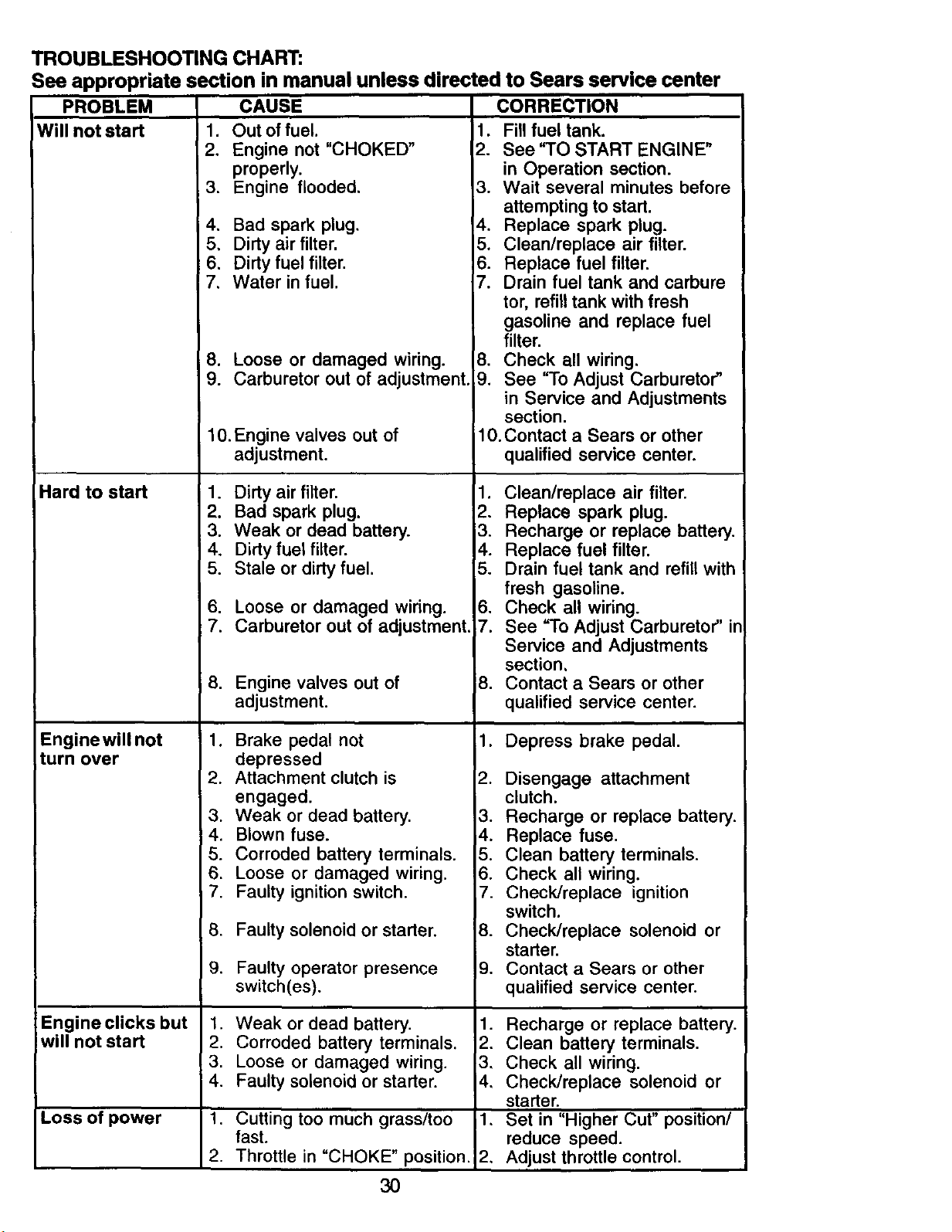
TROUBLESHOOTING CHART:
See appropriate section in manual unless directed to Sears service center
PROBLEM
Will not start
Hard to start
Enginewill not
turn over
Engine clicks but
will not start
CAUSE
1. Out of fuel.
2. Engine not "CHOKED"
properly.
3. Engine flooded, 3.
4, Bad spark plug. 4.
5, Dirty air filter. 5.
6, Dirty fuel filter. 6.
7, Water in fuel. 7.
8. Loose or damaged wiring. 8.
9. Carburetor out of adjustment. 9.
10. Engine valves out of
adjustment.
1. Dirty air filter. 1.
2. Bad spark plug. 2.
3. Weak or dead battery. 3.
4. Dirty fuel filter. 4.
5. Stale or dirty fuel. 5.
6. Loose or damaged wiring. 6.
7. Carburetor out of adjustment. 7.
8. Engine valves out of 8.
adjustment.
1. Brake pedal not 1.
depressed
2. Attachment clutch is 2.
engaged.
3. Weak or dead battery. 3.
4. Blown fuse. i4.
5. Corroded battery terminals. 5.
6. Loose or damaged wiring. 6.
7. Faulty ignition switch. 7.
8. Faulty solenoid or starter. 8.
9. Faulty operator presence 9.
switch(es).
1. Weak or dead battery. 1.
2. Corroded battery terminals. 2.
3. Loose or damaged wiring. 3,
4. Faulty solenoid or starter. 4,
1. Cutting too much grass/too 1,
fast.
2. Throttle in "CHOKE" position. 2,
Loss of power
3O
CORRECTION
1. Fill fuel tank.
2. See "TO START ENGINE"
in Operation section.
Wait several minutes before
attempting to start.
Replace spark plug.
Clean/replace air filter.
Replace fuel filter.
Drain fuel tank and carbure
tor, refill tank with fresh
gasoline and replace fuel
filter.
Check all wiring,
See "To Adjust Carburetor"
in Service and Adjustments
section.
10. Contact a Sears or other
qualified service center.
Clean/replace air filter.
Replace spark plug.
Recharge or replace battery.
Replace fuel filter.
Drain fuel tank and refill with
fresh gasoline.
Check all wiring.
See "To Adjust Carburetor" ir
Service and Adjustments
section,
Contact a Sears or other
qualified service center.
Depress brake pedal.
Disengage attachment
clutch.
Recharge or replace battery.
Replace fuse.
Clean battery terminals.
Check all wiring.
Check/replace ignition
switch.
Check/replace solenoid or
starter.
Contact a Sears or other
qualified service center.
Recharge or replace battery.
Clean battery terminals.
Check all wiring.
Check/replace solenoid or
starter.
Set in "Higher Cut" position/
reduce speed.
Adjust throttle control.
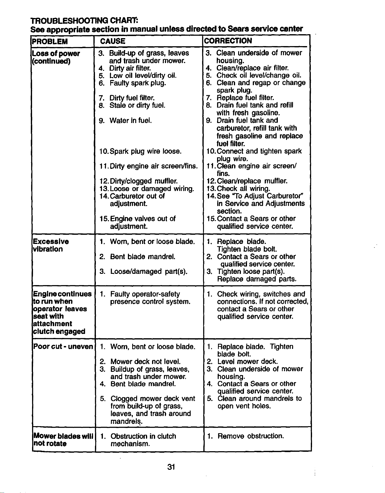
TROUBLESHOOTING CHART:
See appropriate section in manual unless directed to Sears service center
CAUSE CORRECTION
3. Build-up of grass, leaves
and trash under mower.
4. Dirty air filter.
5. Low oil level/dirty oil.
6. Faulty spark plug.
7. Dirty fuel filter.
8. Stale or dirty fuel.
9. Water in fuel.
PROBLEM
Loss of power
(continued)
Excessive
vibration
Engine conUnues
to run when
operator leaves
seat with
attachment
:lutch engaged
Poor cut - uneven
Mower blades will
not rotate
10.Spark plug wire loose.
11. Dirty engine air screen/fins.
12. Didy/clogged muffler.
13. Loose or damaged wiring.
14. Carburetor out of
adjustment.
15.Engine valves out of
adjustment.
1. Wom, bent or loose blade.
2. Bent blade mandrel.
3. Loose/damaged part(s).
1. Faulty operator-safety
presence control system.
1. Wom, bent or loose blade.
2. Mower deck not level.
3. Buildup of grass, leaves,
and trash under mower.
4. Bent blade mandrel.
,
Clogged mower deck vent
from build-upof grass,
leaves, and trash around
mandrels.
1. Obstructionin clutch
mechanism.
3. Clean underside of mower
housing.
4. Clean/replace air filter.
5. Check oil level/change oil.
6. Clean and regap or change
spark plug.
7. Replace fuel filter.
8. Drain fuel tank and refill
with fresh gasoline.
9. Drain fuel tank and
carburetor, refill tank with
fresh gasoline and replace
fuel filter.
10.Connect and tighten spark
plug wire.
11.Clean engine air screen/
fins.
12. Clean/replace muffler.
13.Check all wiring.
14.See =ToAdjust Carburetor"
in Service and Adjustments
section.
15.Contact a Sears or other
qualified service center.
1. Replace blade.
Tighten blade bolt.
2. Contact a Sears or other
qualified service center.
3. Tighten loose part(s).
Replace damaged pads.
.
Check wiring, switches and
connections. If not corrected
contact a Sears or other
qualified service center.
1. Replace blade. Tighten
blade bolt.
_2. Level mower deck.
3. Clean underside of mower
housing.
:4. Contact a Sears or other
qualified service center.
5. Clean around mandrels to
open vent holes.
1. Remove obstruction.
31
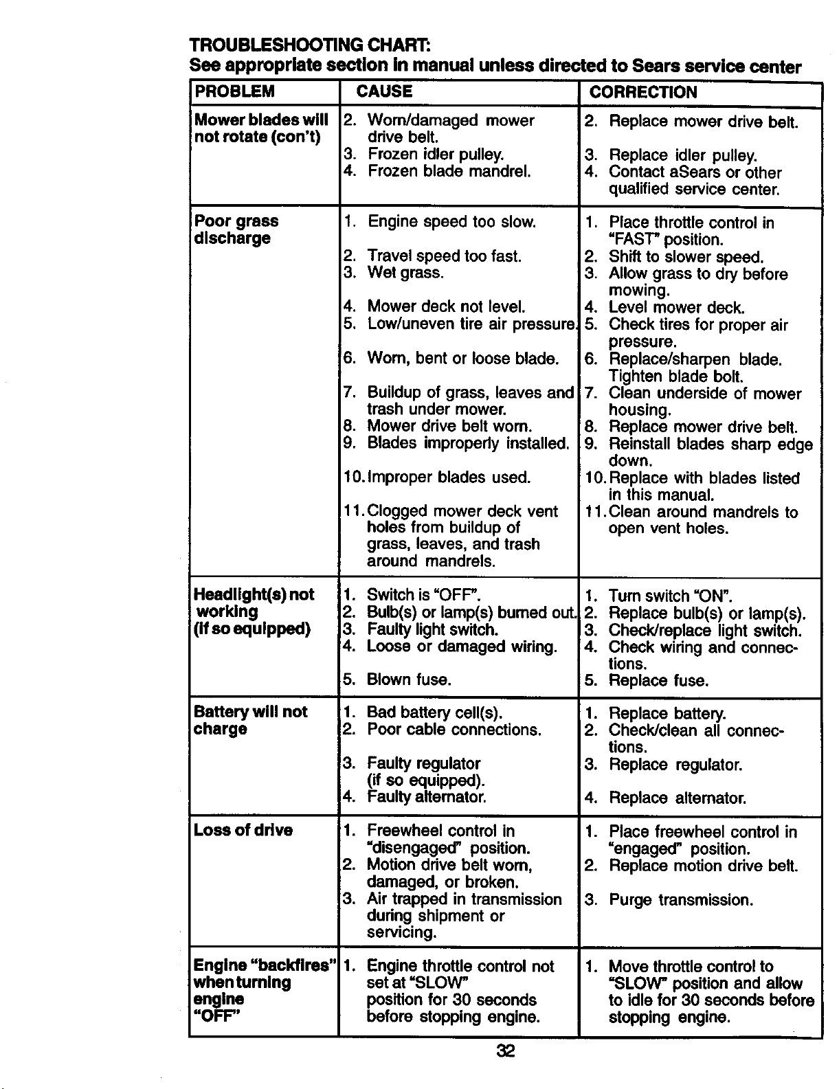
TROUBLESHOOTING CHART:
See appropriate section In manual unless directed to Sears service center
PROBLEM CAUSE CORRECTION
Mower blades will
not rotate (con't)
Poor grass
discharge
Headlight(s) not
working
(if so equipped)
Battery will not
charge
Loss of drive
2. Worn/damaged mower
drive belt.
3. Frozen idler pulley.
4. Frozen blade mandrel.
1. Engine speed too slow.
2. Travel speed too fast.
3. Wet grass.
4. Mower deck not level.
5. Low/uneven tire air pressure_
!6. Wom, bent or loose blade.
7. Buildup of grass, leaves and
trash under mower.
8. Mower drive belt worn.
9. Blades improperly installed.
10.Improper blades used.
11.Clogged mower deck vent
holes from buildup of
grass, leaves, and trash
around mandrels.
1. Switchis=OFF".
2. Bulb(s)or lamp(s)bumed out
3. Faulty lightswitch.
4. Loose or damaged wiring.
5. Blown fuse.
1. Bad battery cell(s).
2. Poor cable connections.
3. Faulty regulator
(if so equipped).
4. Faulty altemator.
1. Freewheel control in
"disengaged" position.
2. Motion ddve belt worn,
damaged, or broken.
3. Air trapped in transmission
during shipment or
servicing.
lo
Engine throttle control not
set at =SLOW"
position for 30 seconds
before stopping engine.
32
Engine "backfires"
whenturnlng
engine
"OFF"
2. Replace mower drive belt.
3. Replace idler pulley.
4. Contact aSears or other
qualified service center.
1. Place throttle control in
"FAST" position.
2. Shift to slower speed.
3. Allow grass to dry before
mowing.
4. Level mower deck.
5. Check tires for proper air
pressure.
6. Replace/sharpen blade.
Tighten blade bolt.
7. Clean underside of mower
housing.
8. Replace mower drive belt.
9. Reinstall blades sharp edge
down.
10. Replace with blades listed
in this manual.
11.Clean around mandrels to
open vent holes.
1. Turn switch =ON".
2. Replace bulb(s) or lamp(s).
3. Check/replace light switch.
4. Check wiring and connec-
tions.
5. Replace fuse.
1. Replace battery.
2. Check/clean all connec-
tions.
3. Replace regulator.
4. Replace altemator.
1. Place freewheel control in
=engaged" position.
2. Replace motion drive belt.
3. Purge transmission.
. Move throttlecontrolto
=SLOW" positionand allow
to idle for 30 seconds before
stopping engine.
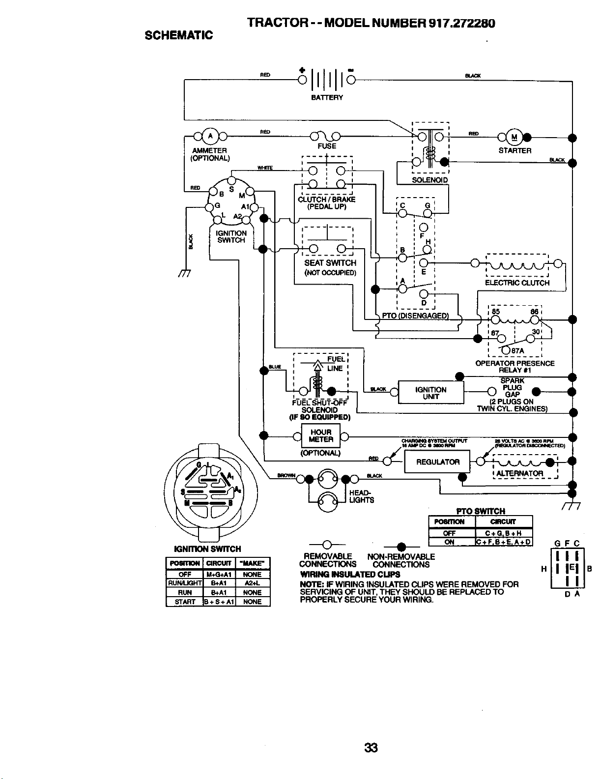
TRACTOR -- MODEL NUMBER 917.272280
SCHEMATIC
AMMETER
(OPTIONAL)
WhY:RE
---( )G AI(
IGNITION
SWITCH
FUSE
L ....... J
CLUTCH/ BRAKE
(PEDAL UP)
D
L ......
; -;U-E_:
•-_ ,_: uNe:
I o IGNITION
t........ UNIT
SOLENOID I
(IF 80 EQUIPPED)
i (o_no.AL) _ _ REQULA'roR
HE_- [
I
I
u STARTER
L __t
OPERATOR PRESENCE
RELAy #1
!' SPARK
_2 LUG
GAP
PLUGS ON
o ALTERNATOR I
Fro 8wn'cH
POI110N
OFF
REMOVABLE NON-REMOVABLE
CONNECTIONS CONNECTIONS
WIRING INSULATED CLIPS
NOTE: IF WIRING INSULATED CLIPS WERE REMOVED FOR
SERVICING OF UNIT, THEY SHOULD BE REPLACED TO
PROPERLY SECURE YOUR WIRING.
QRCtAT
C+GnS+H
+FrB+EnA+D
GFC
DA
33
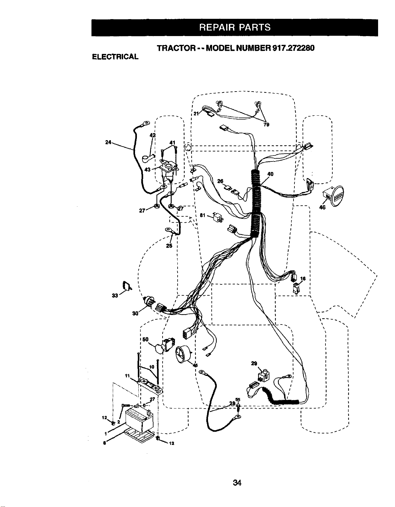
TRACTOR -- MODEL NUMBER 917.272280
ELECTRICAL
4O
/I
/I
/I
I
34
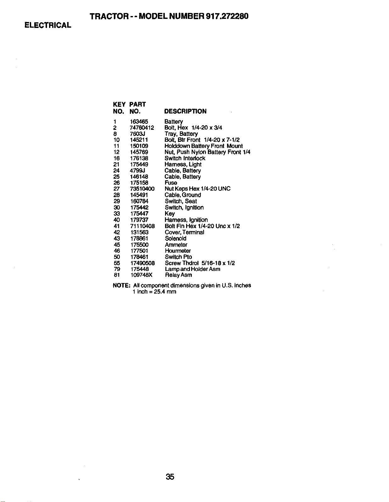
ELECTRICAL
TRACTOR -- MODEL NUMBER 917.272280
KEY PART
NO. NO. DESCRIPTION
1 163465 Battery
2 74760412 Bolt,Hex 1/4-20 x 3/4
8 7603J Tray, Battery
10 145211 Bolt, Btr Front 114-20x 7-1/2
11 150109 HolddownBatteryFront Mount
12 145769 Nut,Push NylonBatteryFront114
16 176138 SwitchInterlock
21 175449 Hamess,Light
24 4799J Cable, Battery
25 146148 Cable, Battery
26 175158 Fuse
27 73510400 NutKepsHex 1/4-20 UNC
28 145491 Cable,Ground
29 160784 Switch,Seat
30 175442 Switch,Ignition
33 175447 Key
40 179737 Hamess, Ignition
41 71110408 Bolt FinHex 1/4-20 Uncx 1/2
42 131563 Cover,Terminal
43 178861 Solenoid
45 175500 Ammeter
46 177501 Hourmeter
50 178461 SwitchPto
55 17490508 ScrewThdrol 5/16-18 x 1/2
79 175448 LampandHolderAsm
81 109748X RelayAsm
NOTE:
AllcomponentdimensionsgiveninU.S. inches
1 inch= 25.4 mm
35
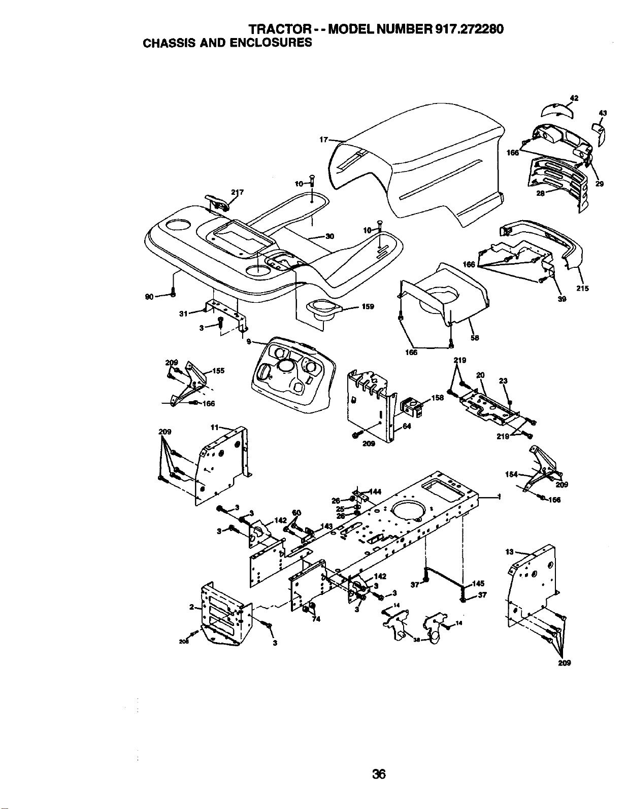
TRACTOR -- MODEL NUMBER 917.272280
CHASSIS AND ENCLOSURES
42
29
31
166
19
23
215
39
2O9
36
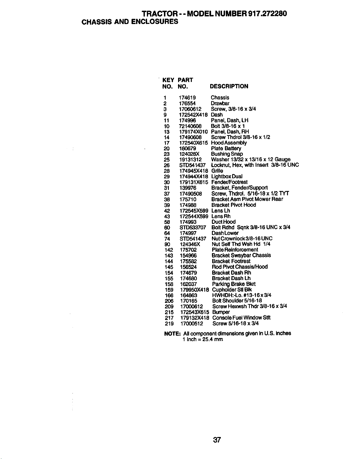
TRACTOR - - MODEL NUMBER 917.272280
CHASSIS AND ENCLOSURES
• KEY PART
NO. NO. DESCRIPTION
1 174619 Chassis
2 176554 Drawhar
3 17060612 Screw,3/8-16 x 3/4
9 172542X418 Dash
11 174996 Panel,Dash,LH
10 72140608 Bolt3/8-16 x 1
13 179174X010 Panel,Dash,RH
14 17490608 ScrewThdrol3/8-16x 1/2
17 172540X615 HoodAssembly
20 180679 PlateBattery
23 124028)( BushingSnap
25 19131312 Washer13/32x 13/16x 12 Gauge
26 STD541437 Locknut,Hex, withInsert 3/8-16 UNC
28 174945X418 Grille
29 174944X418 LIghtboxDual
30 179131X615 Fender/Footrast
31 139976 Bracket,Fender/Support
37 17490508 Screw,ThdraL 5/16-18x 1/2TY'r
38 175710 BracketAsmPivotMowerRear
39 174988 BracketPivotHood
42 172545X599 LensLh
43 172544X599 LensRh
58 174993 DuctHood
60 STD533707 BoltRdhd Sqnk3/8-16UNCx3/4
64 174997 DashLower
74 STD541437 NutCrownlock3/8-16UNC
90 124346X Nut SelfThdWshHd 1/4
142 175702 PlateReinforcement
143 154966 BracketSwaybarChassis
144 175582 BracketFootrest
145 156524 RodPivotChassis/Hood
154 174679 BracketDashRh
155 174680 BracketDash Lh
158 162037 ParkingBrakeBkrt
159 179950X418 CupholderStlBIk
166 164863 HWHDH:-Lo.#13-16x3/4
206 170165 BoltShoulder5/16-18
209 17000612 ScrewHexwshThdr3/8-16 x3/4
215 172543X615 Bumper
217 179132X418 ConsoleFuelWindowSUt
219 17000512 Screw5/16-18 x 3/4
NOTE: AllcomponentdimensionsgiveninU.S. inches
1 inch= 25.4 mm
37
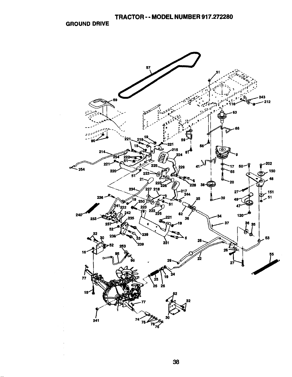
TRACTOR -- MODEL NUMBER 917.272280
GROUND DRIVE
77
1
241
26 26
229
$2
3O
41
" 150
1
38
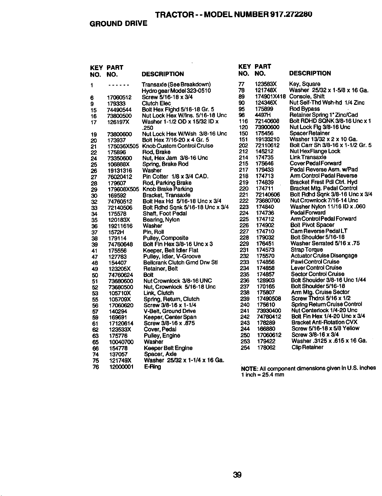
TRACTOR - - MODEL NUMBER 917.272280
GROUND DRIVE
KEY PART KEY PART
NO. NO. DESCRIPTION NO. NO. DESCRIPTION
1 ...... Transaxle(SeeBreakdown) 77
HydrogearModel323-0510 78
6 17060512 Screw5/16-18 x 3/4 89
9 179333 ClutchElec 90 124346X
15 74490544 BoltHexFlghd5/16-18 Gr. 5 95 175899
16 73800500 Nut Lock HexW/Ins. 5/16-18 Unc 96 4497H
17 126197X Washer1-1/20D x 15/32 ID x 116 72140608
.250 120 73900600
19 73800600 Nut LockHexW/Wsh 3/8-16 Unc 150 175456
20 173937 BoltHsx7/16-20 x 4 Gr. 5 151 19133210
21 175036X505 KnobCustomControlCruise 202 72110612
22 175896 Rod,Brake 212 145212
24 73350600 Nut,Hex Jam 3/8-16 Unc 214 174735
25 106888X Spdng,BrakeRod 215 175646
26 19131316 Washer 217 179433
27 76020412 PinCotter I/8 x 3/4 CAD. 218 174713
28 179607 ROd,ParkingBrake 219 174839
29 179608X505 KnobBrakeParking 220 174711
30 169592 Bracket,Transaxls 221 72140606
32 74760512 BoltHex Hd 5/16-18 Unc x 3/4 222 73680700
33 72140506 BoltRdhd Sqnk5/16-18 Uncx 3/4 223 174840
34 175578 Shaft,FootPedal 224 174736
35 120183X Beadng,Nylon 225 174712
36 19211616 Washer 226 174902
37 1572H Pin,Roll 227 174710
38 179114 Pulley,Composite 228 179032
39 74760648 Bolt FinHex3/8-16 Uncx 3 229 176451
41 175556 Keeper, BeltIdler Flat 231 174573
47 127783 Pulley,Idler,V-Groove 232 175570
48 154407 BellcrankClutchGmdDrwStl 233 174856
49 123205X Retainer,Belt 234 174858
50 74760624 Bolt 235 174857
51 73680600 NutCrownlock3/8-16 UNC 236 128..o03
52 73680500 Nut,Crownlock5/16-18 Unc 237 170165
53 105710X Link,Clutch 238 175807
55 105709X Spdng,Retum,Clutch 239 174..o0508
56 1706o0620 Screw3/8-16 x 1-1/4 240 175610
57 140294 V-Belt,GroundDdve 241 73930400
59 169691 Keeper,CenterSpan 242 74780412
61 17120614 Screw3/8-16 x .875 243 178289
62 123533X Cover,Pedal 244 166880
63 175776 Pulley,Engine 250 17060612
65 10040700 Washer 253 179422
66 154778 KeeperBeltEngine 254 178062
74 137057 Spacer,Axle
75 121749X Washer 25/32 x 1-1/4 x 16 Ga.
76 12000001 E-Ring
123583X Key,Square
121748X Washer 25/32 x 1-5/8x 16 Ga.
174901X418 Console,Shift
Nut Self-ThdWsh-hd 1/4Zinc
RodBypass
RetainerSpring1"Zinc/Cad
BoltRDHD SQNK 3/8-16Uncx 1
NutLockFig3/8-16 Unc
SpacerRetainer
Washer 13/32 x 2 x 10 Ga.
Bolt CarrSh 3/8-16 x 1-1/2Gr. 5
NutHexFlangeLock
LinkTransaxle
CoverPedalForward
PedalReverseAsm.w/Pad
ArmControl PedalReverse
BracketFrastPdlCtd. Hyd
BracketMtg.Pedal Control
BoltRdhdSqnk 3/8-16 Uocx 3/4
NutCrownlock7/16-14 Unc
WasherNylon11/16 ID x .060
PedalForward
ArmControlPedalForward
BoltPivotSpacer
CamReversePedalLT
Bolt Shoulder5/16-18
WasherSerrated5/16 x .75
StrapTorque
ActuatorCruiseDisengage
PawiControlCruise
LeverControlCruise
SectorControl Cruise
Bolt Shoulder3/6-16 Unc 1/44
BoltShoulder5/16-18
ArmMtg.CruiseSector
Screw Thdrot5/16 x 1/2
SpdngReturnCruiseControl
NutCentarlock1/4-20 Unc
BoltFinHex 1/4-20Uncx 3/4
BracketAnti-RotationCVX
Screw5/16-18x 5/8Yellow
Screw 3/8-16 x 3/4
Washer .3125 x .615 x 16 Ga.
ClipRetainer
NOTE: AllcomponentdimensionsgiveninU.S.Inches
1 inch= 25.4 mm
39
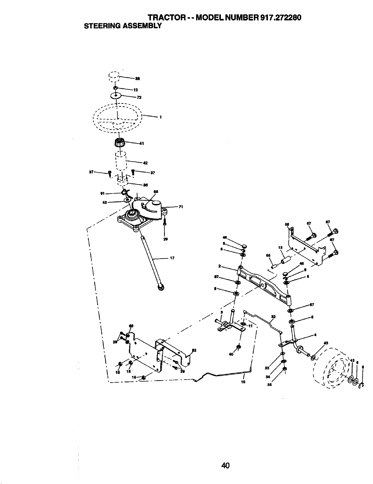
TRACTOR - - MODEL NUMBER 917.272280
STEERING ASSEMBLY
i II • .... _______.JI1--'----''" 1j
t
/ 17
i
18
40
10
40
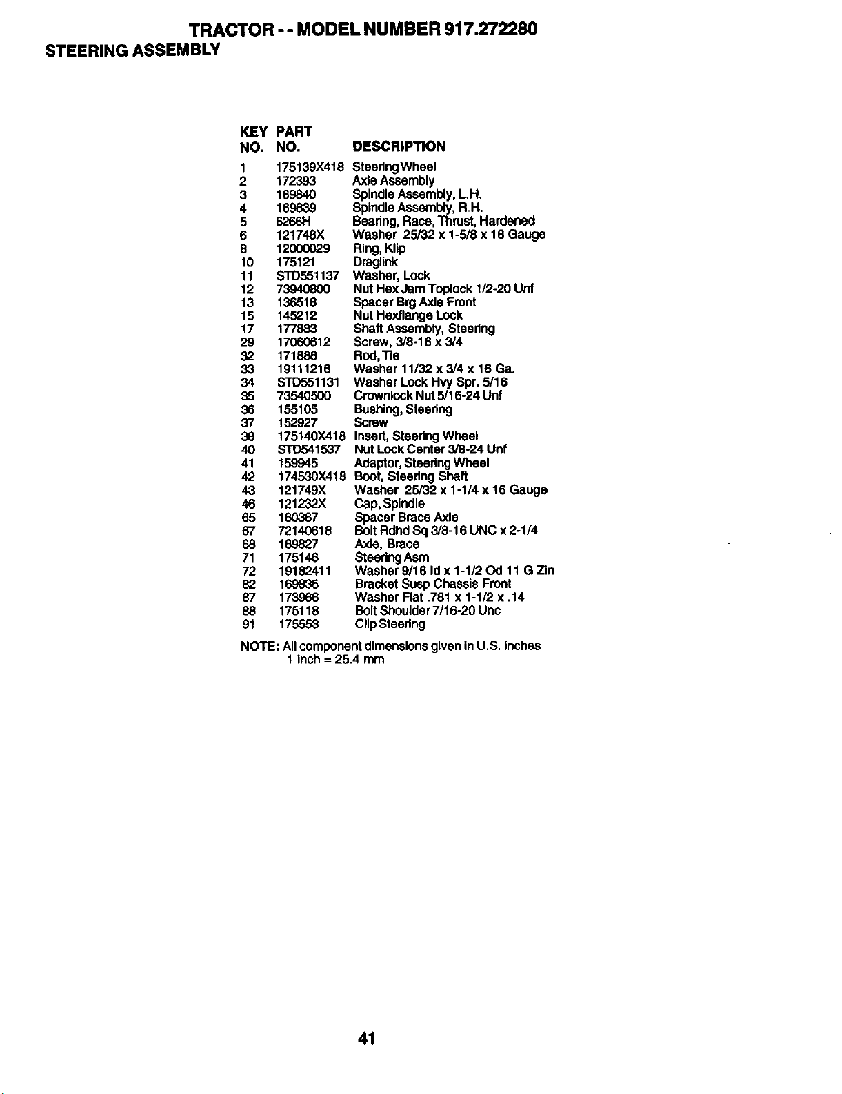
TRACTOR -- MODEL NUMBER 917.272280
STEERING ASSEMBLY
KEY PART
NO. NO. DESCRIPTION
1 175139X418
2 172393
3 169840
4 169839
5 6266H
6 121748X
8 12000029
10 175121
11 STD551137
12 73940800
13 136518
15 145212
17 177883
29 17060612
32 171888
33 19111216
34 STD551131
35 73540500
36 155105
37 152927
38 175140X418
40 STD541537
41 159945
42 174530X418
43 121749X
46 121232X
65 160367
67 72140618
68 169827
71 175146
72 19182411
82 169835
87 173966
88 175118
91 175553
SteedngWheel
AxleAssembly
SpindleAssembly,L.H.
SpindleAssembly,R.H.
Bearing,Race, Thrust,Hardened
Washer 25/32 x 1-5/8 x 16 Gauge
Ring,Klip
Draglink
Washer, Lock
NutHaxJam Toplock1/2-20Unf
SpacerBrgAxle Front
NutHexflangaLock
ShaftAssembly,Steering
Screw,3/8-16 x 3/4
Rod,Tie
Washer 11/32 x 3/4 x 16 Ga.
WasherLockHvySpr. 5/16
CrownlockNut5/16-24Unf
Bushing,Steering
Screw
Insert,SteedngWheel
NutLockCenter3/8-24 Unf
Adaptor,SteedngWheel
Boot,SteeringShaft
Washer 25/32 x 1-1/4 x 16 Gauge
Cap,Spindle
SpacerBraceAxle
BoltRdhdSq3/8-16 UNC x 2-1/4
Axle,Brace
SteeringAsrn
Washer9/16 Idx 1-1/20d 11 G Zin
BracketSuspChassisFront
WasherFlat .781 x 1-1/2 x .14
BoltShoulder7/16-20 Unc
ClipSteering
NOTE: All component dimensions given in U.S. inches
1 inch = 25,4 mm
41
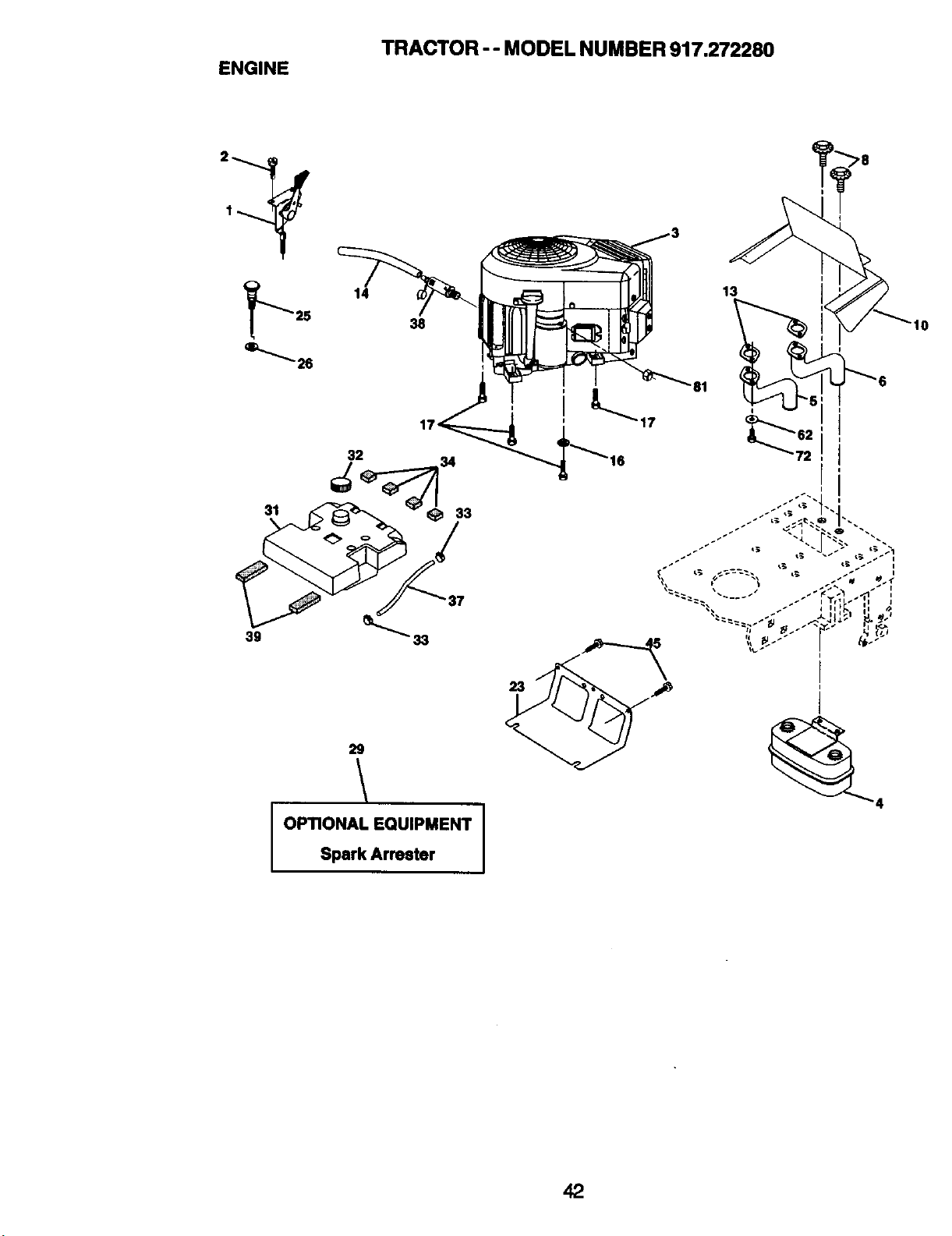
TRACTOR -- MODEL NUMBER 917.272280
ENGINE
F 14
25 38
_''_ 26
39 33
29
\
OPTIONAL EQUIPMENT
Spark Arrester
42
TRACTOR -- MODEL NUMBER 917.272280
ENGINE
KEY PART
NO. NO, DESCRIPTION
1 175437X505 Control,ThmtUe
2 164863 ScrewHwhdH.-Lo#13016 x 3/4
3 ....... Engine,(SeeBreakdown)B&SModelNumber
446T/7-O165-E1
4 149723 Muffler
5 159955 Pipe ExhaustLh
6 160589 Pipe Exhaus!Rh
8 171877 Bolt5/16-18 Unc x 3/4
10 162797 ShieldHeat
13 165391 Gasket
(See EngineBreakdown)
14 148456 TubeDrainOil Easy
16 11050600 Washer, Look,ExternalTooth 3/8
17 17060624 Screw 3/8-16 x 1-1/2
23 169837 Shield,Browning/ DebrisGuard
25 175440X505 ChokeControl
26 73920600 Nut,Keps 3/8-24 Unf
29 137180 Kit,SparkArrestor
31 179022 TankFue/
32 179124X418 CapAsm Fuel
33 123487X Clamp,Hose
34 106082X Pad, Spacer
37 8543R Line,Fuel
38 148315 PlugDrainOil Easy
39 109227X Pad, Idler
45 170(X_12 ScrewHexwshThdr3!8-16 x3/4
62 10040500 WasherLock5/16
72 71070512 ScrewHexCap 5/16-18 x 3/4
81 73510400 NutKepsHex 1/4-20 UNC
NOTE: AllcomponentdimensionsgivenInU.S. inches
1 Inch = 25.4 mm
43
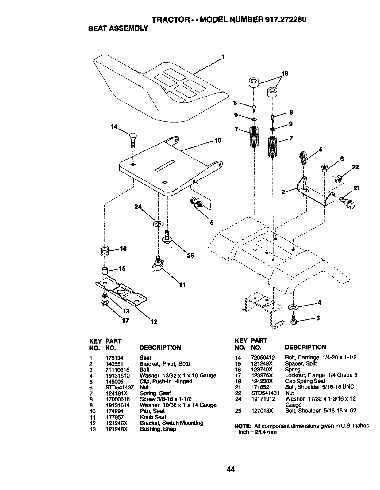
TRACTOR -- MODEL NUMBER 917.272280
SEATASSEMBLY
KEY PART KEY PART
NO. NO. DESCRIPTION NO. NO. DESCRIPTION
1 175134 Seat 14 72050412
2 140551 Bracket,Pivot,Seat 15 121249X
3 71110616 Bolt 16 123740X
4 19131610 Washer 13/32 x 1x 10 Gauge 17 123976X
5 145006 Clip,Push-In Hinged 18 124238X
6 STD541437 Nut 21 171852
7 124181X Spring,Seat 22 STD541431
8 17000616 Screw3/8-16 x 1-1/2 24 19171912
9 19131614 Washer 13/32 x I x14 Gauge
10 174894 Pan, Seat 25 127018X
11 177957 KnobSeat
12 121246X Bracket,SwitchMounting
13 121248X Bushing,Snap
Bolt, Carriage 1/4-20 x 1-1/2
Spacer,Split
Spdng
Locknut,Flange 1/4 Grads 5
Cap SpringSeat
Bolt,Shoulder 5/16-18 UNC
Nut
Washer 17/32 x 1-3/16 x 12
Gauge
Bolt, Shoulder 5/16-18 x .62
NOTE: AllcomponentdimensionsgiveninU.S. inches
1 Inch= 25.4 mm
44
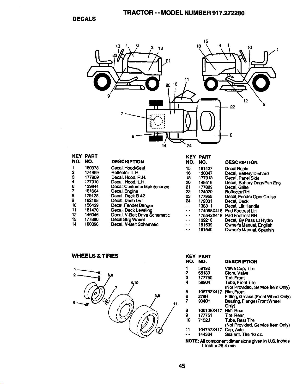
TRACTOR - - MODEL NUMBER 917.272280
DECALS
13
6
3 18
15
18 4
11
10
KEY PART
NO. NO,
1 18O978
2 174969
3 177909
4 177910
6 133644
7 181604
8 179128
9 182168
10 156439
11 181470
12 146046
13 177890
14 160396
9
8
14
KEY PART
DESCRIPTION NO. NO.
Decal,Hood/Seat 15 181427
Reflector L.H. 16 138047
Decal,Hood,R.H. 18 177913
Decal,Hood,L.H. 20 149516
Decal,CustomerMaintenance 21 177889
Decal,Engine 22 174970
Decal,Deck B42 23 177955
Decal,DashLwr 24 172331
Decal,FenderDanger - - 138311
Decal,DeckLeveling - - 174998X418
Decal,V-BeltDdve Schematic - - 175542X418
DecalStrgWheel - - 169210
Decal,V-BeltSchematic - - 181539
- - 181540
12
DESCRIPTION
DecalReplc
Decal,BatteryDiehard
Decal,PanelSide
Decal,Battery Dngr/PsnEng
Decal,Gdlle
ReflectorRH
Decal,FenderOperCruise
Decal,Deck
Decal,LiftHandle
Pad FootrestLH
PadFootrestRH
Decal,By Pass LtHydro
Owner'sManual,English
Owner'sManual,Spanish
WHEELS & TIRES
2 _ 5,8
4,10
11
KEY PART
NO. NO. DESCRIPTION
1 59192 ValveCap,Tire
2 65139 Stem,Valve
3 177750 Tire,Front
4 59904 Tube,FrontTire
(NotProvided,ServiceItemOnly)
5 106732X417 Rim,Front
6 2781-1 Fitting,Grease(FrontWheelOnly)
7 9040H Bearing,Flange(FrontWheel
Only)
8 106108X417 Rim,Rear
9 177751 Tire,Rear
10 7152J Tube,RearTire
(Not Provided,ServiceItemOnly)
11 104757X417 Cap, Axle
- - 144334 Sealant,Tire 10 oz.
NOTE: AllcomponentdimensionsgivenInU.S.Inches
1 inch= 25.4 mm
45
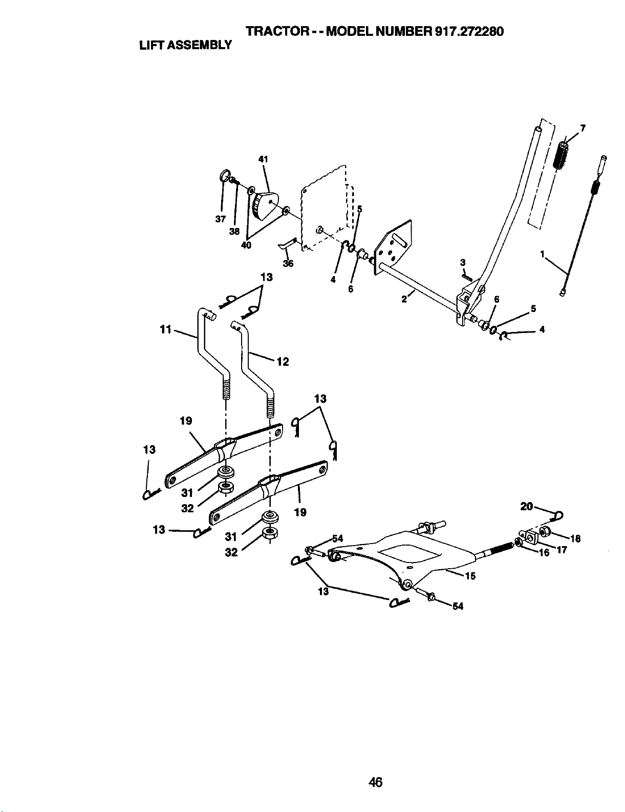
TRACTOR - - MODEL NUMBER 917.272280
LIFT ASSEMBLY
7
19
13
32
37
38
4O
31
32
41
13
13
3
4
6
6
46
TRACTOR-- MODEL NUMBER 917.272280
LIFTASSEMBLY
KEY PART
NO. NO. DESCRIPTION
1 179504 PlungerAssembly
2 159476 ShaftAssembly,Lift
3 178981 Pin,Groove
4 12000002 E-Ring
5 19211621 Washer 21/32 x I x 21 Gauge
6 120183X Beadng,Nyion
7 175830 Grip,Handle,Fluted
11 139865 link, Lift,L.H.
12 139866 Link, Lift,R.H.
13 4939M RetainerSpdng
15 175562 PlateAsmSuspensionFront
16 73350800 NutJam Hax 1/2-13 Unc
17 175689 TrunnionFrontSusp.
18 73800800 NutLockw/Wsh 1/2-13 Unc
19 139868 ArmAsm.SuspensionMower
20 1635.52 RetainerSpdng
31 169865 TrunionSups.Arm.BaadngPivot
32 73540600 NutCrowniock3/8-24
36 155097 PointerHeightIndicator
37 123935X PlugHole
38 17060516 Screw5/16-18 x 1
40 19112410 Washer 11/32 x 1-1/2 x 10 Ga
41 155098 IndicatorHeightStlt
54 175560 PinFlange
NOTE: All component dimensions given in U.S. inches
1 inch= 25.4 mm
47
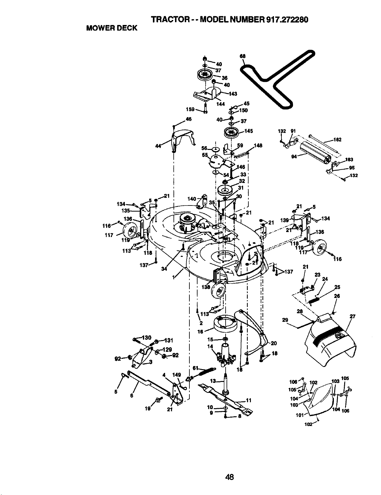
TRACTOR - - MODEL NUMBER 917.272280
MOWER DECK
i9"_ 144
140-
.134
117
I
16
14
5
i
i!
i!
i!
i!
27
29
,_ lO2 ,o,,,°5
,>,<"'2JJ
10_101_04 1!. 106
48
TRACTOR - - MODEL NUMBER 917.272280
MOWER DECK
KEY PART
NO. NO.
1 182032
2 STD533107
3 138017
4 165460
5 $10624008
6 178024
8 850857
9 STD551137
10 140296
11 139775
13 137645
14 128774
15 110485X
16 174493
17 72110614
18 72140505
19 132827
20 159770
21 STD541431
23 177563
24 105304X
25 123713X
26 110452X
27 130968X428
28 19111016
29 131491
30 173984
31 129963
32 153.535
33 178342
36 131494
37 STD551037
40 STD541437
44 14OO88
45 $10624003
46 137729
54 133943
55 155046
56 165723
59 141043
61 174882
DESCRIPTION
KEY PART
NO. NO.
MowerDeckAssembly,42" 68 174883
Bolt 91 180532
BracketAssembly,Sway Bar, 92 STD541437
Front 94 132264
BracketSway Bar 38/42" Deck 95 180533
RetainerSpdng 101 136420
BarSway Deck 102 71081010
Boll, Hex 3/8-24 x 1.25 Gr. 8 103 19061216
Washer, Lock 104 STD551110
Washer,Hardened 105 160793
Blade,MulchingPremium 106 2029J
ShaftAssembly,Mandrel,Vented 116 137644
Housing,Mandrel,Vented 117 174873
Bearing,Ball,Mandrel 118 73930600
Stripper,VentedMowerDeck 119 19121414
Boll Rdhd3/8-16 x 1-3/4 x Gr. 5 129 19131312
Bolt, Carriage 5/16-18 x 5/8 130 STD523710
Bolt,Shoulder 131 STD533710
Baffle,Vortex 132 17060612
NutCrownlock5/16-18UNC 134 156941
Bracket,Deflector 135 155989
Cap,Sleeve 136 155986
Spring,Torsion,Deflector 137 72110505
Nut,Push 138 155992
Shield,Deflector 139 159644
Washer 11/32x5/8x16Ga. 140 159643
Rod,Hinge 143 157109
ScrewThdRoUDodPt.Hex 144 158634
Washer,Spacer 145 165888
Pulley,Mandrel 146 171977
Nut,Toplock,Flanged 148 169022
Pulley,Idler,Flat 149 165898
Washer 13/32x13/16x16Ga. 150 19091216
NutCrownlock3/8-16 UNC 159 72140614
Guard,Mandrel,LH. 182 179126
Retalcer 183 163552
Screw,Thd. Roll 1/4-20x 5/8 - - 130794
Washer,Hardened
Arm,Idler
Spacer,Retainer
Guard,TUV Idler - - 181542
Spdng Ext.ElectClutch
DESCRIPTION
V-Belt
BracketRollerNoseLH
Nut
RollerNows38-50
BracketRollerNose RH
MulcharCover
Screw
Washer #10
Washer,Lock
LatchAssembly,Bagger
Nut,Weld
Bolt shoulder
WheelGaugeRally
Nut Centedock3/6-16
Washer 3/8 x 7/8 x 14 Ga.
Washer 13/32 x 13/16x 12 Ga.
Bolt, FinHax3/8-16 UNCx 1 Gr.5
Boll,RdhdSqnk3/8-16UNC x 1
Screw3/8-16 x 3/4
PinHead Rivet
BracketWhl. Gauge RearLH
ChannelAdj.Whl Gauge
BoltCan"Short5/16-18 x 5/8
BracketWhl. GaugeRear RH
BracketWhlGauge FrontRH
BracketWhtGauge FrontLH
BracketArm Idler42"
KeeperBelt42"ClutchCable
PulleyIdler Rat
BoltCarriageIdler
SpringReturnIdler
RetainerSpringYellowZinc
Washer 9/32 x 3/4 x 16 Ga.
BoltTdhd Sgn3/8-16UNC x 1-3/4
RodRollerNose
RetainerSpdngZinc
MandrelAssembly(Includes
Housing,Shaftand Shaft
HardwareOnly- PulleyNot
Included)
ReplacementMower,Complete
NOTE: AllcomponentdimensionsgiveninU.S. Inches
1 Inch=25.4 mm
49
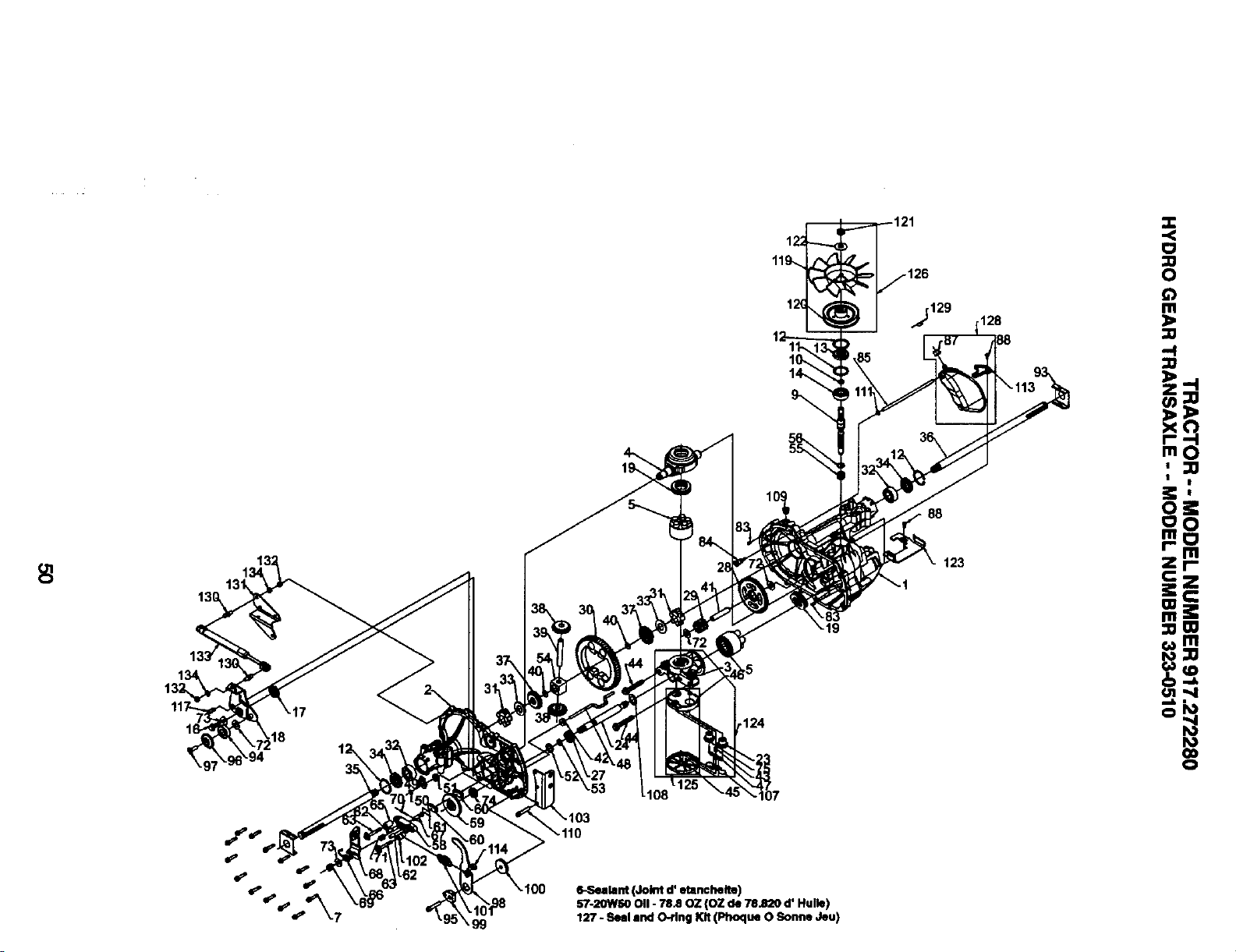
13(!
99
19
124
6-Sealant (Joint d' etlnchelte)
b'7-2OWSO011- 78.80Z (OZ de 78.820 d' Hulle)
127- Seal and O-ring Kit (Phoque 0 Sonne Jeu)
88
123
128
=0
o
0
|
|
oi:
oO
mo
r-- m
Zl-
c z
i: €
m
m J:
::0m
r_CD
O1"4
mlk •
b.1
0
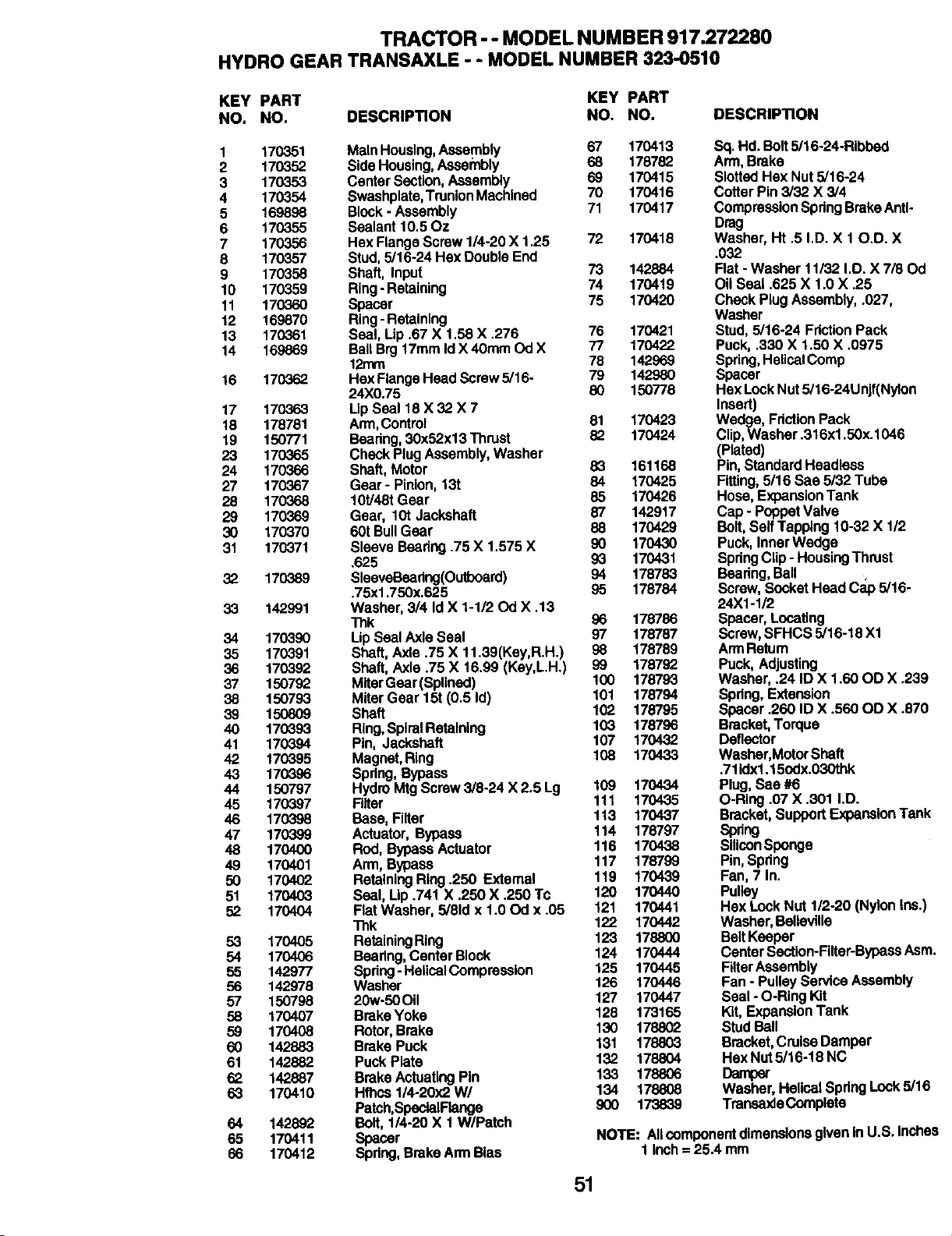
TRACTOR -- MODEL NUMBER 917.272280
HYDRO GEAR TRANSAXLE - - MODEL NUMBER 323-0510
KEY PART KEY PART
NO. NO. DESCRIPTION NO. NO. DESCRIPTION
1 170351 MainHousing,Aseambly 67 170413
2 1703,52 Side Housing,Assehlbly 68 178782
3 170353 CenterSection,Assembly 69 170415
4 170354 Swashplate,TrunlonMachined 70 170416
5 169898 Block- Assembly 71 170417
6 170355 Sealant10.50z
7 170356 HexFlangeScrew1/4-20X 1.25 72 170418
8 170357 Stud,5/16-24 HexDoubleEnd
9 170358 Shaft, Input 73 142884
10 170359 Ring- Retaining 74 170419
11 170360 Spacer 75 170420
12 169870 Ring-Retaining
13 170361 Seal, Lip .67X 1.58 X .276 76 170421
14 169869 BallBrg17mmIdX 40mmOd X 77 170422
12rnm 78 142969
16 170362 HexFlangeHeadScrew5/16- 79 142980
24X0.75 80 150778
17 170363 LipSeal 18 X 32 X 7
18 178781 Arm,Control 81 170423
19 150771 Beadng,30x52x13 Thrust 82 170424
23 170365 CheckPlugAssembly,Washer
24 170366 Shaft,Motor 83 161168
27 170367 Gear- Pinion,13t 84 170425
28 170368 10t/48tGear 85 170426
29 170369 Gear, 10t Jackshaft 87 142917
30 170370 60t BullGear 88 170429
31 170371 SleeveBearing.75X 1.575 X 90 170430
.625 93 170431
32 170389 SleavaBeadng(Outboard) 94 178783
.75xl .750x.625 S5 178784
33 142991 Washer,314IdX 1-1/20d X .13
Thk 96 178786
34 170390 LipSealAxle Seal 97 178787
35 170391 Shaft,Axle .75 X 11.39(Key,R.H.) 98 178789
36 170392 Shaft, Axle.75 X 16.99 (Key,L.H.) 99 178792
37 150792 MiterGear(Splined) 100 178793
38 150793 MiterGear 15t (0.5 Id) 101 178794
39 150809 Shaft 102 178795
40 170393 Ring,SpiralRetaining 103 178796
41 170394 Pin, Jackshaft 107 170432
42 170395 Magnet,Ring 108 170433
43 170396 Spring,Bypass
44 150797 HydroMtg Screw3/8-24 X 2.5 Lg 109 170434
45 170397 Filter 111 170435
46 170398 Base,Filter 113 170437
47 170399 Actuator,Bypass 114 178797
48 170400 Rod, BypassActuator 116 170438
49 170401 Arm,Bypass 117 178799
50 170402 RetainingRing.250 External 119 170439
51 170403 Seal, Up .741 X .250 X .250 Tc 120 170440
52 170404 Flat Washer, 5/81dx 1.00d x .05 121 170441
Thk 122 170442
53 170405 RetainingRing 123 178800
54 170406 Bearing,CenterBlock 124 170444
55 142977 Spdng- HeUcelCompression 125 170445
56 142978 Washer 126 170446
57 150798 20w-50Oil 127 170447
58 170407 BrakeYoke 128 173165
59 170408 Rotor,Brake 130 178802
60 142883 BrakePuck 131 178803
61 142882 PuckPlate 132 178804
62 142887 BrakeActuatingPin 133 178806
63 170410 Hfhcs 1/4-20)<2W/ 134 178808
Patch,SpectalFtanga 900 173839
64 142892 Bolt, 1/4-20X 1 W/Patch
65 170411 Spacer
66 170412 Spdng,BrakeArmBias
Sq. Hd.Bait 5/16-24-Ribbed
Arm,Brake
SlottedHex Nut5/16-24
CotterPin 3/32 X 3/4
CompressionSpdngBrakeAnti-
Drag
Washer, Ht .5 I.D. X 10.D. X
.032
Flat - Washer 11/32 I.D. X 7/80d
Oil Seal .625 X 1.0 X .25
Check PlugAssembly,.027,
Washer
Stud,5/16-24 FdctionPack
Puck,.330 X 1.50 X .0975
Spdng,HelicalComp
Spacer
HexLockNut5/16-24Unjf(Nylon
Insert)
Wedge, FdcUonPack
Clip,Washer.316xl .50x.1046
(Plated)
Pin,StandardHeadless
Fitting,5/16 Saa 5/32Tube
Hose,ExpansionTank
Cap - PoppetValve
Bolt,SelfTapping10-32 X 1/2
Puck,InnerWedge
SpdngClip- HousingThrust
Beadng,Ball
Screw,SocketHead C_o 5/16-
24X1-1/2
Spacer,Locating
Screw,SFHCS 5/16-18 Xl
ArmRetum
Puck,Adjusting
Washer, .24 ID X 1.60OD X .239
Spdng,Extension
Spacer.260 ID X .560OD X .870
Bracket,Torque
Deflector
Washer,MotorShaft
.711dxl.15edx.030thk
Plug,Sac #6
O-Ring .07X .301 I.D.
Bracket,SupportExpansionTank
Spdng
SiliconSponge
Pin,Spdng
Fan,7 In.
Pulley
HexLockNut 1/2-20 (NylonIns.)
Washer,BeUavtlle
BeltKeeper
CenterSection-Filter-BypassAsm.
FilterAssembly
Fan - PulleyServiceAssembly
Seal - O-RingKit
Kit,ExpansionTank
StudBall
Bracket,CruiseDamper
HexNut5/16-18 NC
Dampar
Washer,HelicalSpdngLock5/16
TransaxleComplete
NOTE: AllcomponentdimensionsgivenIn U.S. Inches
1 inch= 25.4 mm
51
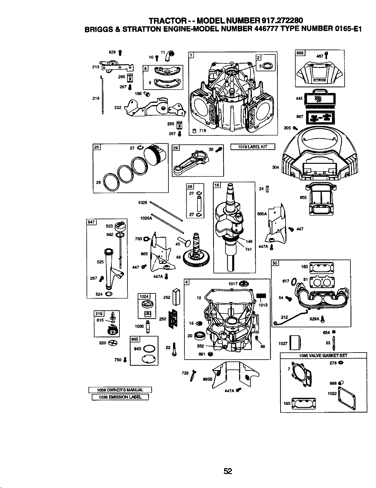
TRACTOR - - MODEL NUMBER 917.272280
BRIGGS & STRAI-rON ENGINE-MODEL NUMBER 446777 TYPE NUMBER 0165-E1
52_t lOt 11_i)
I I
216 222
265
2678
10_6
4,47A
447A
t 1058 OWNER'S MANUAL I 447A
3O5
447
1027 _ 5310Q5VALVE GAS_T_ SET
276 0
52
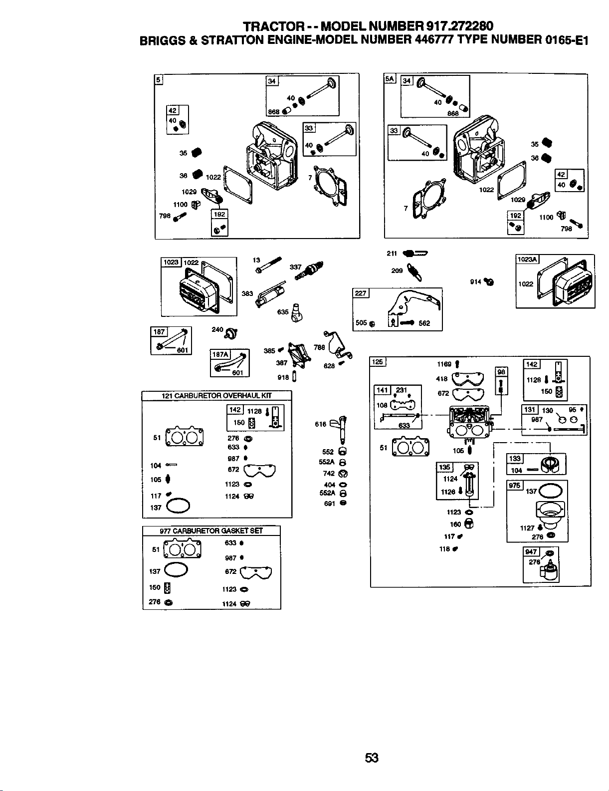
TRACTOR -- MODEL NUMBER 917.272280
BRIGGS & STRA'I'rON ENGINE-MODEL NUMBER 446777 TYPE NUMBER 0165-E1
36 _ 1022
1029
1100
798
1100 _
240_
918 []
121 CARBURETOR OVERHAUL Kn"
51 L_,_(_^I 276 0
633e
987 I
104 _ 672
105 0 1123 0
11"/"• 1124
SS2A8
742_'_
4O40
_8
691 O
9?7 CARBURETOR GASKET SET
51 _ _33e
987 •
150
276 Q 1124 _
211
++%
914 _1_
lO8(_
633
1169 1
105 0 "--'--'-I
117 • 276 0
118 •
53
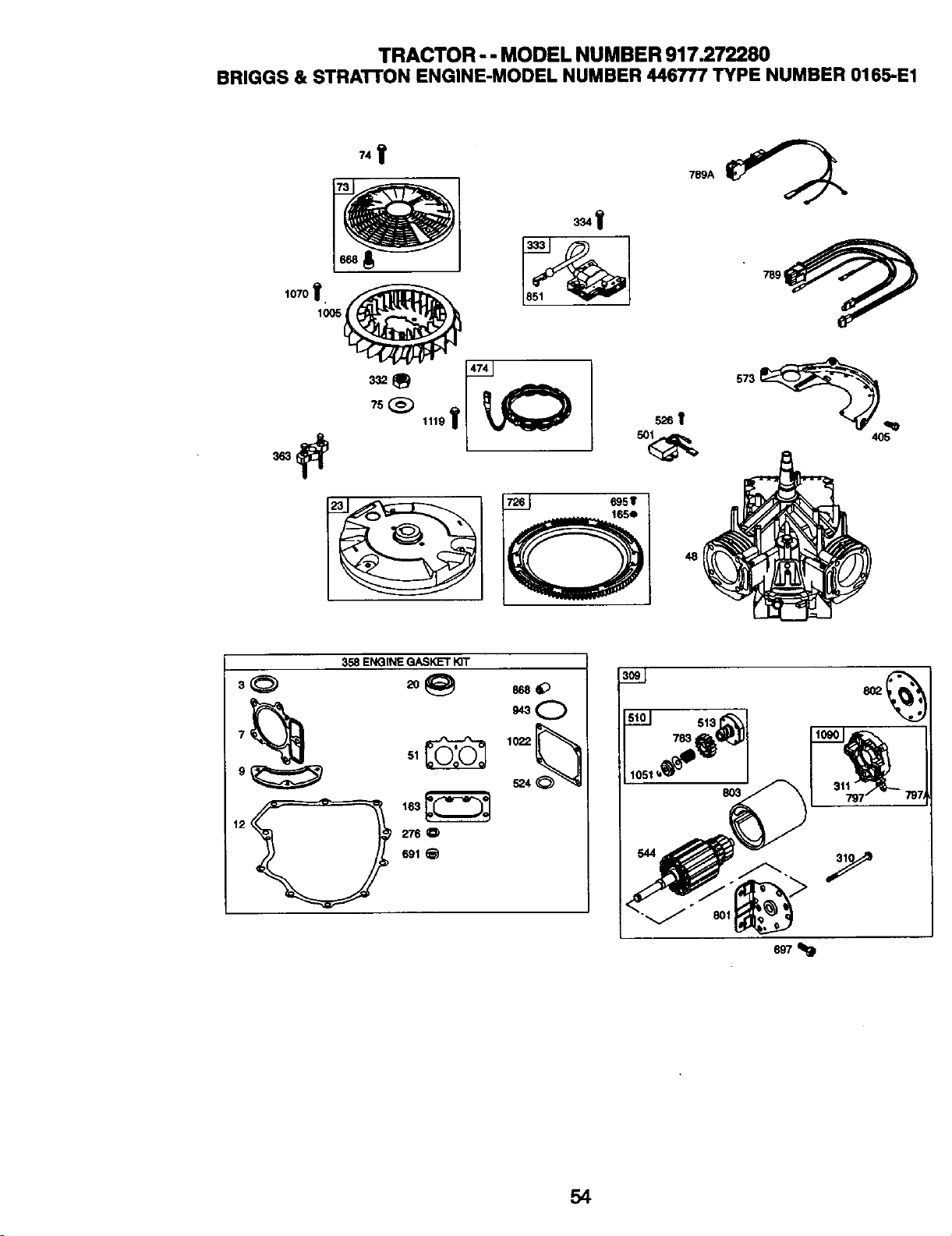
TRACTOR -- MODEL NUMBER 917.272280
BRIGGS & STRATTON ENGINE-MODEL NUMBER 446777 TYPE NUMBER 0165-E1
,,Y
my
474 I
789A
4115
358 ENGINE GASKET KIT
51 _ 1022
9 _ 524
12 276 0
691
513 _ 1
1051_'_ 803 I 31_7_ 797_
"-._" ®_
54
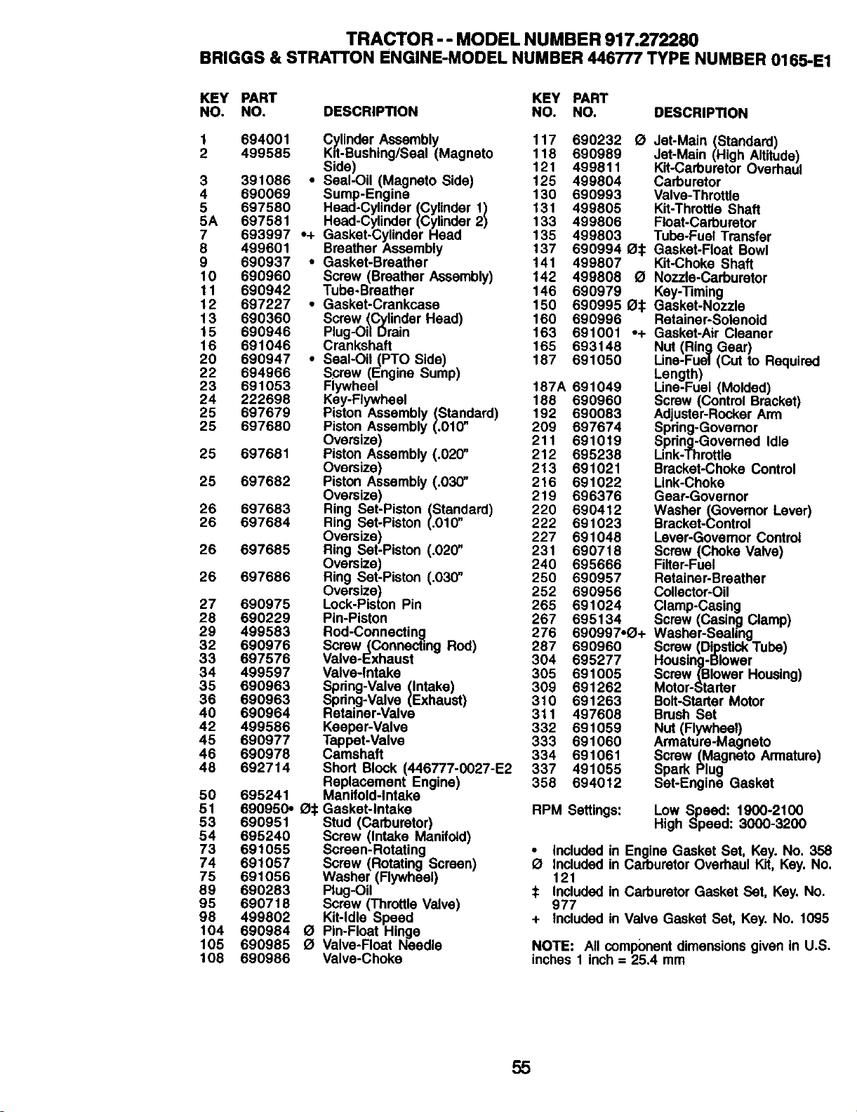
TRACTOR -- MODEL NUMBER 917.272280
BRIGGS & BTRATTON ENGINE-MODEL NUMBER 446777 TYPE NUMBER 0165-E1
KEY PART KEY PART
NO. NO. DESCRIPTION NO. NO. DESCRIPTION
1 694001 C_inder Assembly 117 690232
2 499585 Kd-Bushing/Seal (Magneto 118 690989
Side) 121 499811
3 391086 ,, Seal-Oil (Magneto Side) 125 499804
4 690069 + Sump-Engine 130 690993
5 697580 Head-Cylinder (Cylinder 1) 131 499805
5A 697581 Head-Cylinder (Cylinder 2) 133 499806
7 693997 • Gasket-Cylinder Head 135 499803
8 499601 Breather Assembly 137 690994
9 690937 • Gasket-Breather 141 499807
10 690960 Screw (Breather Assembly) 142 499808
11 690942 Tube-Breather 146 690979
12 697227 ° Gasket-Crankcase 150 690995
13 690360 Screw (Cylinder Head) 160 690996
15 690946 Plug-Oil Drain 163 691001
16 691046 Crankshaft 165 693148
20 690947 ° Seal-Oil (PTO Side) 187 691050
22 694966 Screw (Engine Sump)
23 691053 Flywheel 187A 691049
24 222698 Key-Flywheal 188 690960
25 697679 Piston Assembly (Standard) 192 690083
25 697680 Piston Assembly (.010" 209 697674
Oversize) 211 691019
25 697681 Piston Assembly (.02(7' 212 695238
Oversize) 213 691021
25 697682 Piston Assembly (.030" 216 691022
Oversize) 219 696376
26 697683 Ring Set-Piston (Standard) 220 690412
26 697684 Ring Set-Piston (.010" 222 691023
Oversize) 227 691048
26 697685 Ring Set-Piston (.020" 231 690718
Oversize) 240 695666
26 697686 Ring Set-Piston (.030" 250 690957
Oversize) 252 690956
27 690975 Lock-Piston Pin 265 691024
28 690229 Pin-Piston 267 695134
29 499583 Rod-Connecting 276 690997,_+
32 690976 Screw(Connecting Rod) 287 690960
33 697576 Valve-Exhaust 304 695277
34 499597 Valve-Intake 305 691005
35 690963 Spring-Valve (Intake) 309 691262
36 690963 Spring-Valve (Exhaust) 310 691263
40 690964 Retainer-Valve 311 497608
42 499586 Keeper-Valve 332 691059
45 690977 Tappet-Valve 333 691060
46 690978 Camshaft 334 691061
48 692714 Short Block (446777-0027-E2 337 491055
Replacement Engine) 358 694012
50 695241 Manifold-Intake
51 690950. _:1: Gasket-Intake
53 690951 Stud (Carburetor)
54 695240 Screw (Intake Manifold)
73 691055 Screen-Rotating o
Included in
74 691057 Screw (Rotating Screen) O
Included in
75 691056 Washer (Flywheel) 121
89 690283 Plug-Oil _ Included in
95 690718 Screw (Throttle Valve) 977
98 499802 Kit-Idle Speed + Included in
104 690984 O Pin-Float Hinge
105 690985 O Valve-Float Needle
108 690986 Valve-Choke
O Jet-Main (Standard)
Jet-Main (High Altitude)
Kit-Carburetor Overhaul
Carburetor
Valve-Throttle
Kit-Throttle Shaft
Float-Carburetor
Tube-Fuel Transfer
_:[: Gasket-Float Bowl
Kit-Choke Shaft
£1 Nozzle-Carburetor
Key-Timing
_:[: Gasket-Nozzle
Retainer-Solenoid
•+ Gasket-Air Cleaner
Nut (Ring Gear)
Line-Fuol (Cut to Required
Length)
Line-Fual (Molded)
Screw (Control Bracket)
Adjuster-Rocker Arm
Spring-Governor
Spring-Governed Idle
Link-Throttle
Bracket-Choke Control
Link-Choke
Gear-Governor
Washer (Governor Lever)
Bracket-Control
Lever-Govemor Control
Screw (Choke Valve)
Filter-Fuel
Retainer-Breather
Collector-Oil
Clamp-Casing
Screw (Casi.n_Clamp)
Washer-Sealing
Screw (DipstickTube)
Housing-Blower
Screw _Blower Housing)
Motor-Starter
Bolt-Starter Motor
Brush Set
Nut (Flywheel)
Armature-Magneto
Screw (Magneto Armature)
Spark Plug
Set-Engine Gasket
RPM Settings: Low Speed: 1900-2100
High Speed: 3000-3200
Engine Gasket Set, Key. No. 358
Carburetor Overhaul Kit, Key. No.
Carburetor Gasket Set, Key. No.
Valve Gasket Set, Key. No. 1095
NOTE: All component dimensions given in U.S.
inches 1 inch = 25.4 mm
55
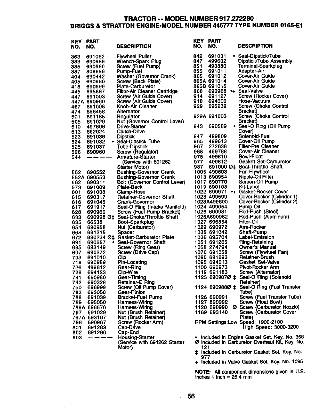
TRACTOR -- MODEL NUMBER 917.272280
BRIGGS & STRA'R'ON ENGINE-MODEL NUMBER 446777 TYPE NUMBER 0165-E1
KEY PART KEY PART
NO. NO. DESCRIPTION NO. NO. DESCRIPTION
363 691062 Rywheel Puller 842 691031 • Seal-Dipstick/Tube
383 690966 Wrench-Spark Plug 847 499602 Dipstick/Tube Assembly
385 690960 Screw (Fuel Pump) 851 493880 TerminaI-Sparkplug
387 808656 Pump-Fuel 855 691011 Adapter-Air
404 690442 Washer (Govemor Crank) 865 691012 Cover-Air Guide
405 690960 Screw (Back Plate) 865A 691014 Cover-Air Guide
418 690999 Plate-Carburetor 865B 691015 Cover-Air Guide
445 695667 Filter-Air Cleaner Cartridge 868 690968 .+ Seal-Valve
447 691003 Screw (Air Guide Cover) 914 691127 Screw(Rocker Cover)
447A 690960 Screw (Air Guide Cover) 918 694000 Hose-Vanuum
467 691008 Knob-Air Cleaner 929 695239 Screw (Choke Control
474 696458 Alternator Bracket)
501 691185 Regulator 929A 691003 Screw (Choke Control
505 691029 Nut (Govemor Control Lever) Bracket)
510 497606 Drive-Starter 943 690589 ° SeaI-O Ring (Oil Pump
513 692024 Clutch-Drive Cover)
523 691036 Dipstick 947 499809 Solenoid-Fuel
524 691032 * Seal-Dipstick Tube 965 499613 Cover-Oil Pump
525 691037 Tube-Dipstick 967 272638 Filter-Pre Cleaner
526 690960 Screw (Regulator) 968 499788 Cover-Air Cleaner
544 Armature-Starter 975 499810 Bowl-Float
(Service with 691262 977 499812 Gasket Set-Carburetor
Starter Motor) 987 691000 O:1: Seal-Throttle Shaft
552 690552 Bushing-Governor Crank 1005499603 Fan-Flywheel
552A 690553 Bushing-Governor Crank 1013690954 Nipple-Oil Filter
562 690311 Bolt (Govemor Control Lever) 1017690770 Screen-Oil Pump
573 691009 Plate-Back 1019690103 Kit-Label
601 691038 Clamp-Hose 1022690971 °+ Gasket-Rocker Cover
615 690317 Retainer-Governor Shaft 1023499599 Cover-Rocker (Cylinder 1)
616 691045 Crank-Governor 1023A499600 Cover-Rocker (Cylinder 2)
617 691917 SoaI-O Ring(Intake Manifold) 1024499054 Pump-OU
628 690960 Screw (Fuel Pump Bracket) 1026690981 Rod-Push (Steel)
633 690998 _:I: Seal-Choke/Throttle Shaft 1026A690982 Rod-Push (Aluminum)
635 66538 Boot-Sparkplug 1027696854 Filter-Oil
654 690958 Nut (Carburetor) 1029690972 Arm-Rocker
668 691215 Spacer 1035691042 Shaft-Pump
672 690234 _:1: Gasket-Carburetor Plate 1036695704 Label-Emission
691 690657 • Seal-Governor Shaft 1051691265 Ring-Retaining
695 693149 Screw (Ring Gear) 1058274794 Owner's Manual
697 690372 Screw (Drive Cap) 1070691058 Screw (Flywheel Fan)
703 691010 Clip 1090691293 Retainer-Brush
718 690959 Pin-Locating 1095694013 Gasket Set-Valve
726 499612 Gear-Ring 1100690973 Pivot-Rocker Arm
729 694123 Clip-Wire 1119691183 Screw (Aitemator)
741 690980 Gear-Timing 1123690987_1:1: Sesf-O Ring (Solenoid
742 690328 Retainer-E Ring Retainer)
SeaI-O Ring (Fuel Transfer
783750693058696999Gear-Pinionscrew_Oil Pump Cover) 1124690988_1:1: Tube)
788 691039 Bracket-Fuel Pump 1126690991 Screw (Fuel Transfer Tube)
789 695050 Hamees*Widng 1127690992 Screw (Float Bowl)
789A 696576 Hamess-Wiring 1128690990 O Screw (Carburetor Nozzle)
797 691029 Nut (Brush Retainer) 1169693140 Screw (Carburetor Cover
797A 693167 Nut (Brush Retainer) Plate)
798 690967 Screw (Rocker Arm) RPM Settings:Low Speed: 1900-2100
801 691283 Cap-Drive High Speed: 3000-3200
802 691286 Cap-End
803 Housing-Starter
° Included in Engine Gasket Set, Key. No. 358
(ser ce
with 691262 Starter g
Included in Carburetor Overhaul Kit, Key. No.
Motor) 121
:1:Included in Carburetor Gasket Set, Key. No.
977
+ Included in Valve Gasket Set, Key. No. 1095
NOTE: All component dimensions given in U.S.
Inches 1 inch = 25.4 mm
56


58

SUGGESTED GUIDE FOR SIGHTING SLOPES FOR SAFE OPERATION
1. Fold this page along dotted line indicated above.
2. Hold page before you so that its left edge is vertically parallel to a tree
trunk or other upright structure.
3. Sight acroso the fold in the direction of hill slope you want to measure.
4. Compare the angle of the fold with the slope of the hill.

Get it fixed, at your home or ours!
For repairof majorbrand appliancesin your own home...
no matterwho made it,no matter who sold it]
1-800-4-MY-HOME _ AnyOne,dayornight
(1-800A69-4663) (U.S,A.and Canada)
w_Rv,geEBl.conl WWIN.SeSI1LCa
Forrepairof carry-inproductslikevacuums, lawnequipment,and
electronics,callforthe nearestSears Partsand RepairCenter.
1-800-488-1222 Anym_,dayorn_ (U.SAorgy)
wv_v_
For the replacement parts,accessoriesand owner'smanuals
that you need to do-it-yourself,callSears PartsDirectS"t
1-800-366-PART 6 a.m.-11 p.m., 7days aweek
(1-8oo-366-7278) (U.S.A.one,)
www._arLcom/pamdlrect
To purchaseor inquire abouta Sears ServiceAgreement
or Sears Maintenance Agreement:
1-800-827-6655 (u.s.A.) 1-800-361-6665 (Canada)
7 a.m.- 5 p.m.,CST, Mort.- Sat. 9 a.m.- 8 p.m.EST, M- F, 4 p.m.Sat.
Parapedr _ dereparack_ a
domici_o,y paraordenarpiezas:
1.888-SU-HOGAR su
(1-888-784-6427)
AuCanadapourserviceenfran(;_
1-800-LE-r--OYERuc
(1-8oo-533-6937)
www.sears.ca
© Sears, Roebuckand Co
® Registered Trademark / r_ Trademark / SMService Mark of Sears, Roebuck and Co
® Marca Reg=strada / rMMarca de F_bnca / s_ Marca de Serv=clo de Sears, Roebuck and Co
MCMarque de commerce / MOMarque deposee de Sears, Roebuck and Co
181539 Rev. 2 3.20.02 RD PrmtedmU.S.A.


