
Loading ...
Loading ...
Loading ...
10 − English
FEATURES
KNOW YOUR COMPOUND MITER SAW
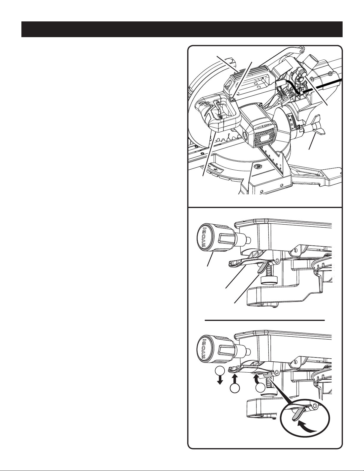
See Figure 1.
The safe use of this product requires an understanding of the
information on the tool and in this operator’s manual as well
as a knowledge of the project you are attempting. Before use
of this product, familiarize yourself with all operating features
and safety rules.
10 IN. BLADE
A 10 in. blade is included with the compound miter saw. It will
cut materials up to 3-1/2 in. thick or 12 in. wide, depending
upon the angle at which the cut is being made.
BEVEL LOCK KNOB
The bevel lock knob securely locks your compound miter saw
at desired bevel angles. A positive stop adjustment screw has
been provided on each side of the saw arm. These adjust-
ment screws are for making fine adjustments at 0° and 45°.
CARRYING HANDLE
See Figure 2.
For convenience when carrying or transporting the miter saw
from one place to another, a carrying handle has been provided
on top of the saw arm. To transport, turn off and unplug the
saw, then lower the saw arm and lock it in the down position
by pushing in the lock pin.
NOTE: DO NOT perform any cutting operation with the saw
in the locked position.
DETENT OVERRIDE
See Figure 3.
The detent override allows the miter table to move freely to
any desired angle. With the miter lock handle loosened and the
detent release lever squeezed (1), pull the detent override up (2)
and release the detent release lever (3) to bypass the positive
stops on the miter scale. To release the detent override and
allow the miter table to engage the positive stops, squeeze
and release the detent release lever.
ELECTRIC BRAKE
An electric brake has been provided to quickly stop blade
rotation after the switch is released.
LED LIGHTING SYSTEM
The LED casts a shadow of the blade teeth onto the workpiece
for making precision cuts and predicts blade kerf for blade
cut line.
MITER FENCE
The miter fence on the compound miter saw has been pro-
vided to hold your workpiece securely against when making
all cuts. The right side is larger providing additional support.
SAW ARM LOCKED IN DOWN POSITION
LOCK
PIN
CARRYING
HANDLE
“D”
HANDLE
MITER
LOCK HANDLE
BEVEL
LOCK KNOB
LED GUIDE
SWITCH
Fig. 2
Fig. 3
1
3
2
DETENT
RELEASE LEVER
DETENT
OVERRIDE
Loading ...
Loading ...
Loading ...