Loading ...
Loading ...
Loading ...

9
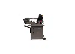
5.4 Mounting band saw to stand
Remove any plastic or holding straps from around
the band saw. Areas of the machine have been
given a protective coating at the factory; this should
be removed using a soft cloth moistened with
kerosene or a cleaner-degreaser. Do not use
gasoline, paint thinner, or lacquer thinner as these
will damage painted surfaces. Do not use an
abrasive pad.
Saw is heavy; two-person lift is
recommended.
See Figure 5-4.
1. Place chip pan (M) on stand. The side with the
mounting holes farther from the edge (X) must
be towards the left.
Figure 5-4
2. Using an assistant, place band saw atop chip
pan (M).
3. Align holes at four corners of saw and chip pan
with holes in stand. Band saw front faces same
direction as JET logo on stand.
4. Install 3/8x1-1/4 hex cap screw (HP1) with flat
washer (HP5) in each of the four holes. When
all four are inserted, tighten screws with 1/2"
wrench.
5. Remove two screws and shipping bracket (Y,
Figure 5-4) which secured the bow during
shipment. Retain these items in case they are
needed for future transporting of machine.
When moving the band saw, the
bow should be in lowered position.
5.5 Handwheel
Install handwheel onto vise lead screw shaft,
aligning the set screw with the flat on the shaft.
Tighten set screw.
5.6 Stock stop
The stock stop is used for making multiple cuts of
the same length.
1. Insert stock stop rod (Figure 5-5) into hole at
front or rear of base, as shown.
2. Secure rod by tightening socket set screw (K
1
,
Figure 5-5) with 3mm hex wrench.
3. The stock stop is moved along the rod by
loosening the socket set screw (K
2
, Figure 5-7)
with 4mm hex wrench. The stock stop can be
reversed on rod to accept slightly longer lengths
of workpieces. Tighten socket set screw (K
2s
)
before beginning operations.
Figure 5-5
5.7 Drip tray
Back out two screws on front or back of machine
base to mount drip tray, as shown in Figure 5-6.
Figure 5-6
Loading ...
Loading ...
Loading ...