Loading ...
Loading ...
Loading ...

1
8
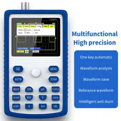
7:Press the [AUTO] button once,The measured PWM waveform is displayed,If
the waveform is too large or too small, press the [S] [ns] [V] [mV] button on the
panel,Zoom in or zoom out the waveform
Signal generator output measurement
Gear selection:The output voltage of the signal generator is within 30V,The
highest test of 1X file is 40V,So 1X gear is sufficient for the output of the test
signal generator.
1:First set the oscilloscope to Auto trigger mode,Auto trigger mode is used to
test periodic signals(The signal output by the signal generator is a p eriodic
signal)
2:Set the oscilloscope to 1X gear
3:The oscilloscope is set to DC coupling mode
4:Plug in the p robe,And turn the switch on the probe handle to the 1X position
5:Ensure that the signal generator is turned on and working and is outputting
signals
6:Connect the probe clip to the black clip of the signal generator output
cable,The probe is connected to the red output wire of the signal generator
7:Press the [AUTO] button once,The waveform output by the generator is
displayed,If the waveform is too large or too small, press the [S] [ns] [V] [mV]
button on the panel,Zoom in or zoom out the waveform
Household mains 220V or 110V measurement
Gear selection:Household electricity is generally 180~260V,The peak-to-peak
voltage is 507~733V,Household electricity in some countries is 110V,The
peak-to-peak voltage is 310V,The 1X file can measure up to 40V,The 10X file
can measure up to 400V,So it needs to be set to 10X gear,That is, the probe and
the oscilloscope must be switched to the 10X gear
Loading ...
Loading ...
Loading ...