Loading ...
Loading ...
Loading ...

1
7
2:Set the oscilloscope to 10X gear
3:Set the oscilloscope to 10X gear
4:Plug in the probe,And turn the switch on the probe handle to the 10X position
5:Make sure the crystal o scillator motherboard is powered on and running
6:Connect the probe clip to the ground wire o f the crystal oscillator main
board(The negative end of the power supply),Pull out the probe cap,Inside is
the needle tip,Touch the tip of the needle to one of the pins of the crystal
oscillator
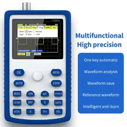
7:Press the [AUTO] button once,The waveform of the measured crystal
oscillator is displayed,If the waveform is too large or too small, press the [S] [ns]
[V] [mV] button on the panel,Zoom in or zoom out the waveform
MOS tube or IGBT PWM signal measurement
Gear selection:
Direct drive MOS tube Or the PWM signal voltage of IGBT is generally within
10V~20V,The PWM pre-control signal is generally within 3~20V,1X Gear can
test up to 40V,So 1X Gear is enough to test the PWM signal(Probe and
oscilloscope are both set to 1X Gear)
1:First set the oscilloscope to Auto trigger mode,Auto trigger mode is used to
test periodic signals(PWM is a periodic sig nal)
2:Set the oscilloscope to 1X gear
3:The oscilloscope is set to DC coupling mode
4:Plug in the p robe,And turn the switch on the probe handle to the 1X position
5:Ensure that the PWM motherboard has PWM signal output at this time
6:Connect the probe clip to the S pole o f the MOS tube,The probe is connected
to the G pole of the MOS tube
Loading ...
Loading ...
Loading ...