Loading ...
Loading ...
Loading ...
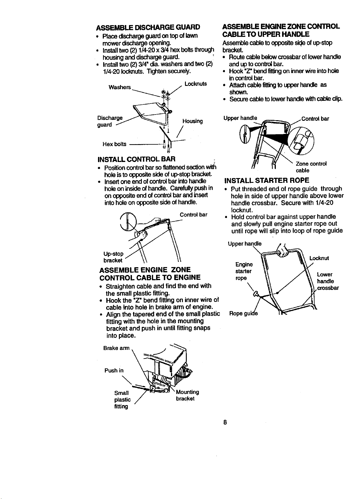
ASSEMBLE DISCHARGE GUARD
• Race discharge guard on top of lawn
mower discharge opening.
• Installtwo (2) 1/4-20 x 3/4 hex boltsthmugll.
housing and discharge guard.
• Installtwo (2) 3/4" die. washers and two (2)
1/4-20 Iocknuts. Tighten securely.
Washers
Hex bolts
. Locknuts
tP
Housing
/
ASSEMBLE ENGINE ZONE CONTROL
CABLE TO UPPER HANDLE
Assemble cable to opposite side ofup-stop
bracket.
• Route cable below crossbar of lower handle
and up to control bar.
• Hook "Z"bend titlingon inner wire into hole
incontrolbar.
• Attach cable fittingto uoper handle as
shown.
• Secure cable to lower handle with cable dip.
Upper handle ,bar
INSTALL CONTROL BAR
• Position control bar soflattened section
hole isto oppositeside of up-stopbracket.
• Insertone end ofcontrolbar intohandle
hole on inside of handle. Carefully push in
on opposite end ofcontrolbar and insert
intohole on opposite side of handle.
Controlbar
Up-stop
ASSEMBLE ENGINE ZONE
CONTROL CABLE TO ENGINE
• Straighten cable and find the end with
the small plastic fitting.
• Hook the "Z" bend fitting on inner wire of
cable into hole in brake arm of engine.
• Align the tapered end of the small plastic
fitting with the hole in the mounting
bracket and push in until fitting snaps
into place.
Brake arm
Zone control
cable
INSTALL STARTER ROPE
• Put threaded end of rope guide through
hole in side of upper handle above lower
handle crossbar. Secure with 1/4-20
Iocknut.
• Hold control bar against upper handle
and slowly pull engine starter rope out
until rope will slip into loop of rope guide
Upper handle
Locknut
Engine
starter
Lower
rope
Push in
\
Small Mounting
plastic bracket
fitting
8
Loading ...
Loading ...
Loading ...