
OWNER MANUAL
MANUALE D’USO
RDNET CONTROL 8
- ‘RDNET’ CONTROL UNIT
- UNITA’ DI CONTROLLO
DELLA RETE “RDNET”


INDEX
INDICE
ENGLISH
SAFETY PRECAUTIONS
INSTALLATION
DESCRIPTION
FRONT PANEL
REAR PANEL
SUBNET CONNECTION
NOTES ABOUT THE RDNET SOFTWARE
RDNET SOFTWARE INSTALLATION
LOUDSPEAKER BYPASS SWITCH
RDNET SOFTWARE (release 1.0.0.68)
ASSIGN AN OBJECT TO A GROUP
ASSIGN AN OBJECT TO AN ALGORITHM
ASSIGNING MULTIPLE OBJECTS TO AN ALGORITHM
EXAMPLE OF ANOTHER OBJECT
RDNET SOFTWARE REPAIR AND REMOVE
SPECIFICATIONS
ITALIANO
AVVERTENZE PER LA SICUREZZA
INSTALLAZIONE
DESCRIZIONE
PANNELLO FRONTALE
PANNELLO POSTERIORE
COLLEGAMENTO DELLE SOTTORETI
NOTE SUL SOFTWARE RDNET
INSTALLAZIONE DEL SOFTWARE RDNET
FUNZIONAMENTO DEL TASTO BYPASS DEI DIFFUSORI
UTILIZZO DEL SOFTWARE RDNET (rif. ver. 1.0.0.68)
ASSEGNAZIONE DI UN MODULO AD UN GRUPPO
ASSEGNAZIONE DI UN MODULO AD UN ALGORITMO
ASSEGNAZIONE MULTIPLA DI MODULI AD UN ALGORITMO
ESEMPIO DI UN ALTRO MODULO
RIPARAZIONE E DISINSTALLAZIONE DEL SOFTWARE RDNET
DATI TECNICI
4
6
6
7
8
9
10
10
14
15
25
26
27
28
28
29
32
34
34
35
36
37
38
38
42
43
53
54
55
56
56
57
4
ENGLISH
IMPORTANT
Before connecting and using this product, please read this instruction manual carefully and
keep it on hand for future reference.
The manual is to be considered an integral part of this product and must accompany
it when it changes ownership as a reference for correct installation and use as well as
for the safety precautions. RCF S.p.A. will not assume any responsibility for the incorrect
installation and / or use of this product.
WARNING: To prevent the risk of fire or electric shock, never expose this product to rain
or humidity.
SAFETY PRECAUTIONS
1. All the precautions, in particular the safety ones, must be read with special
attention, as they provide important information.
2.1 POWER SUPPLY FROM MAINS
a. The mains voltage is sufficiently high to involve a risk of electrocution; therefore, never
install or connect this product when its power cable is plugged in.
b. Before powering up, make sure that all the connections have been made correctly and
the voltage of your mains corresponds to the voltage shown on the rating
plate on the unit, if not, please contact your RCF dealer.
c. The metallic parts of the unit are earthed by means of the power cable.
An apparatus with CLASS I construction shall be connected to a mains socket outlet
with a protective earthing connection.
d. Protect the power cable from damage.
Make sure it is positioned in a way that it cannot be stepped on or crushed by objects.
e. To prevent the risk of electric shock, never open the product: there are no parts
inside that the user needs to access.
3. Make sure that no objects or liquids can get into this product, as this may cause a short
circuit. This apparatus shall not be exposed to dripping or splashing. No objects filled with
liquid, such as vases, shall be placed on this apparatus. No naked sources (such as lighted
candles) should be placed on this apparatus.
4. Never attempt to carry out any operations, modifications or repairs that are not expressly
described in this manual.
Contact your authorized service centre or qualified personnel should any of the following
occur:
- The product does not function (or functions in an anomalous way).
- The power supply cable has been damaged.
- Objects or liquids have got in the unit.
- The product has been subject to a heavy impact.
5. If this product is not used for a long period, disconnect the power cable.
6. If this product begins emitting any strange odours or smoke, switch it off immediately
and disconnect the power supply cable.
7. Do not connect this product to any equipment or accessories not foreseen.
For suspended installation, only use the dedicated anchoring points and do not try to
hang this product by using elements that are unsuitable or not specific for this purpose.
Also check the suitability of the support surface to which the product is anchored (wall, ceiling,
structure, etc.), and the components used for attachment (screw anchors, screws, brackets not
supplied by RCF etc.), which must guarantee the security of the system / installation over time,
also considering, for example, the mechanical vibrations normally generated by transducers.
To prevent the risk of falling equipment, do not stack multiple units of this product unless
this possibility is specified in the user manual.
IMPORTANT
WARNING
SAFETY
PRECAUTIONS

5
ENGLISH
7. Do not connect this product to any equipment or accessories not foreseen.
For suspended installation, only use the dedicated anchoring points and do not try to hang
this product by using elements that are unsuitable or not specific for this purpose.
Also check the suitability of the support surface to which the product is anchored (wall,
ceiling, structure, etc.), and the components used for attachment (screw anchors, screws,
brackets not supplied by RCF etc.), which must guarantee the security of the system /
installation over time, also considering, for example, the mechanical vibrations normally
generated by transducers.
To prevent the risk of falling equipment, do not stack multiple units of this product unless
this possibility is specified in the user manual.
8. RCF S.p.A. strongly recommends this product is only installed by professional
qualified installers (or specialised firms) who can ensure correct installation
and certify it according to the regulations in force.
The entire audio system must comply with the current standards and
regulations regarding electrical systems.
9. Supports and trolleys
The equipment should be only used on trolleys or supports, where necessary, that are
recommended by the manufacturer. The equipment / support / trolley assembly must be
moved with extreme caution. Sudden stops, excessive pushing force and uneven floors may
cause the assembly to overturn.
10. Mechanical and electrical factors need to be considered when installing a professional
audio system (in addition to those which are strictly acoustic, such as sound pressure,
angles of coverage, frequency response, etc.).
11. Hearing loss
Exposure to high sound levels can cause permanent hearing loss. The acoustic pressure
level that leads to hearing loss is different from person to person and depends on the
duration of exposure. To prevent potentially dangerous exposure to high levels of acoustic
pressure, anyone who is exposed to these levels should use adequate protection devices.
When a transducer capable of producing high sound levels is being used, it is therefore
necessary to wear ear plugs or protective earphones.
See the technical specifications in loudspeaker instruction manuals to know their maximum
sound pressure levels.
12. To prevent the occurrence of noise, use screened cables only and avoid putting them
close to:
- Equipment that produces high-intensity electromagnetic fields
(for example, high power transformers)
- Mains cables
- Loudspeaker lines.
13. Situate this product far from any heat sources.
14. Never force the control elements (keys, knobs, etc. ).
15. Do not use solvents, alcohol, benzene or other volatile substances for cleaning the
external parts of this product. Use a dry cloth.
6
ENGLISH
RCF S.P.A. THANKS YOU FOR PURCHASING THIS PRODUCT, WHICH HAS BEEN
DESIGNED TO GUARANTEE RELIABILITY AND HIGH PERFORMANCES.
DESCRIPTION
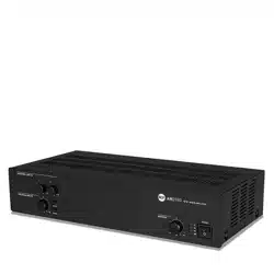
This device can be installed into a 19” rack cabinet (1 unit) with 4 screws, thanks to its
rack ears.
RDNET is a proprietary protocol of a network that allows to connect up to 256
compatible audio devices (i.e. professional RCF loudspeakers mod. TTL55-A, TTL33-A,
TTL31-A, etc.) to a computer (PC with Microsoft Windows® o. s.) to check and remote
control them.
RDNET CONTROL 8 unit routes all data between the PC and audio devices.
The RDNET system allows to monitor every device, checking voltages and currents,
temperatures, audio signal RMS values, cooling fans, etc. .
The PC cyclically requires the RDNET CONTROL 8 unit the operating state of audio
devices that make up the communication network. All data are collected by the central
unit that performs a sequential scan of all audio devices.
Digital address allocation is automatic.
Information relating to the functioning of all audio devices is acquired in real-time,
feature that allows a network global view.
It is possible to check each single audio device and edit its parameters (e.g. output level,
mute, equalization, delay, etc.) by using the PC software.
The audio device overall configuration can be saved as file in the PC and later reloaded.
It is possible to synchronize all parameter values of the RDNET CONTROL 8 unit to the
ones of the PC software preset.
The link between the PC and the RDNET CONTROL 8 unit can be made through either
the USB port or ETHERNET, the latter is useful when the PC is far or it is necessary to link
the RDNET CONTROL 8 unit to an ETHERNET net already wired.
USB link shall be at least version 1.1 (2.0 is OK) and
can be used when the PC is close to the central unit (a
few metres).
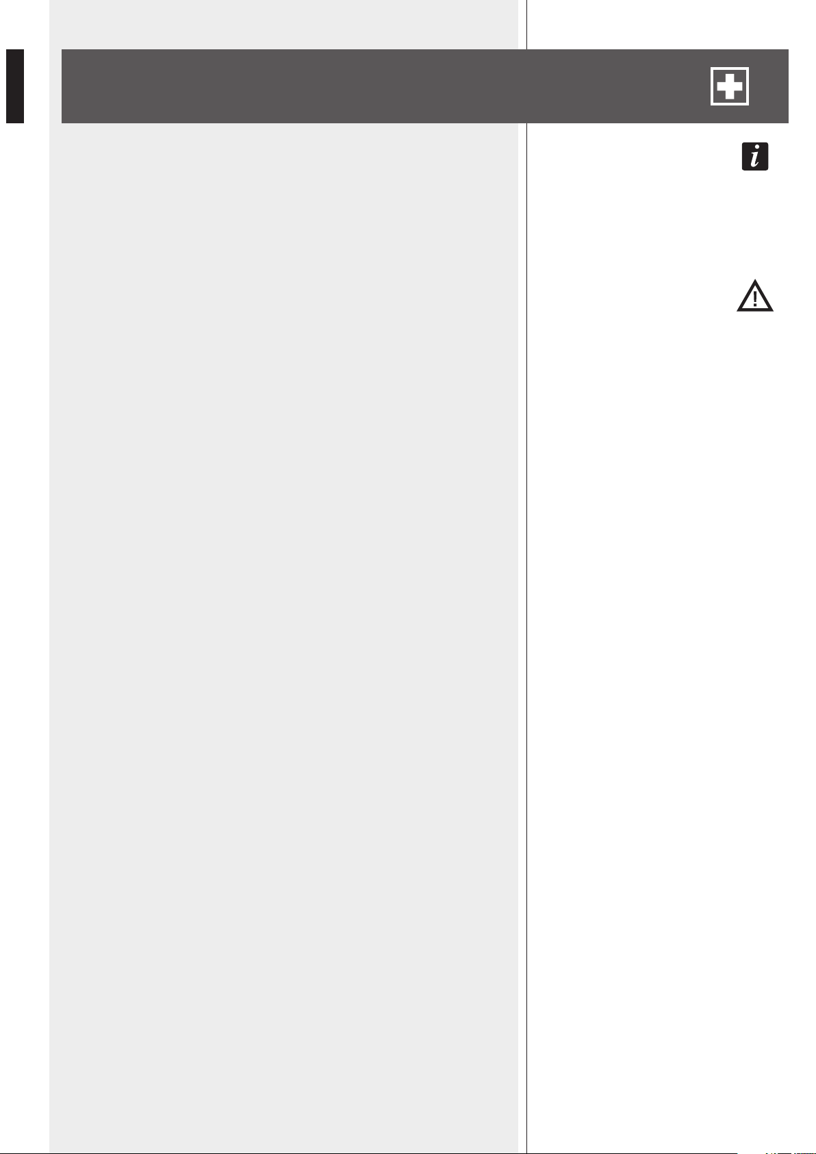
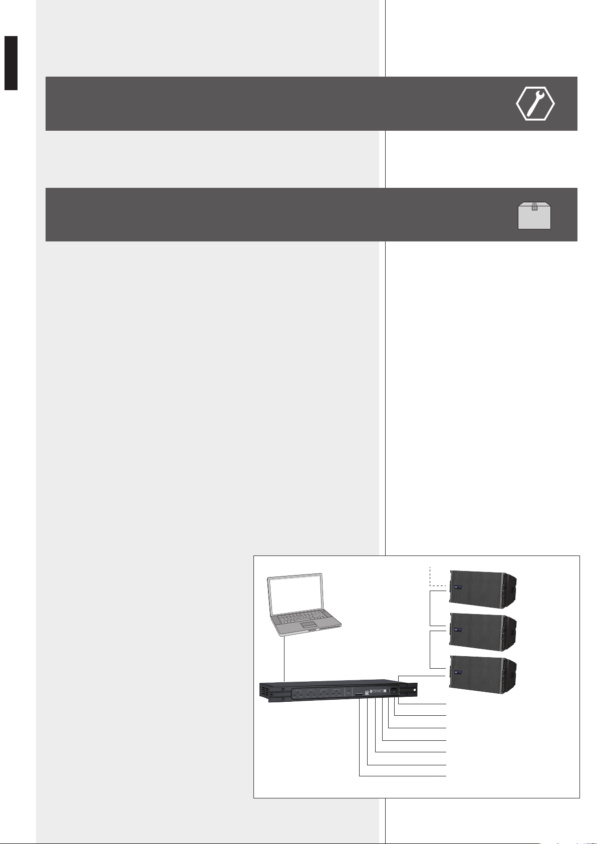
The RDNET CONTROL 8 unit can manage up to 8
subnets. Up to 32 audio devices can be connected
to each subnet (8 subnets x 32 = total 256 audio
devices).
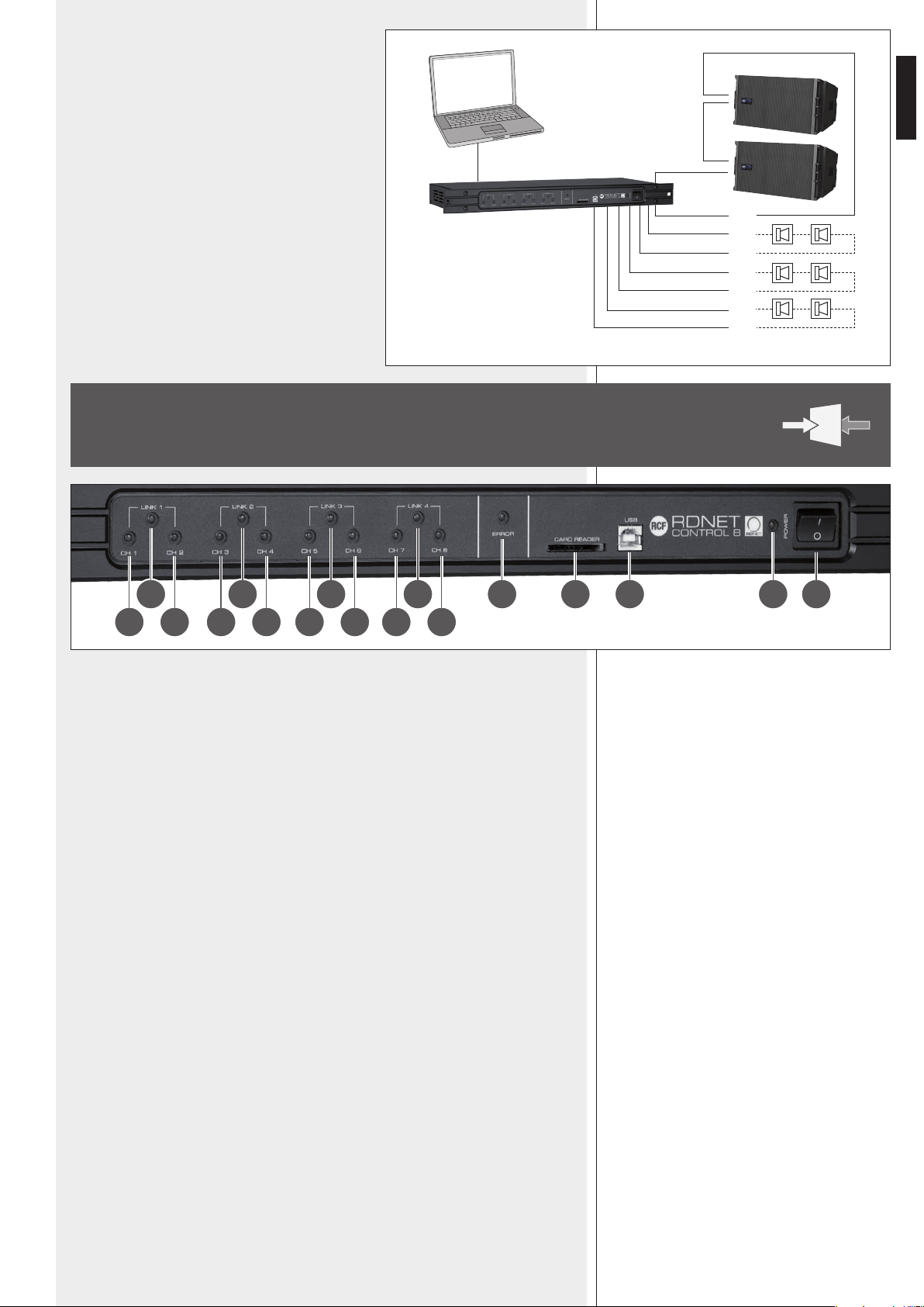
INSTALLATION
PC
USB / ETHERNET
RDNET CONTROL 8
EIA RS-485
AUDIO
DEVICES
(max. 32
per subnet)
SUBNET 1
SUBNET 2
SUBNET 3
SUBNET 4
SUBNET 5
SUBNET 6
SUBNET 7
SUBNET 8
7
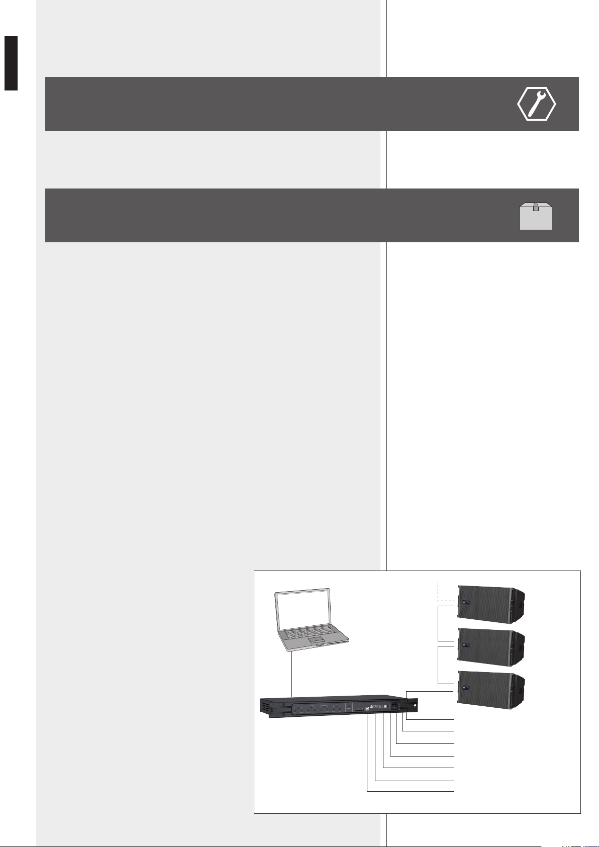
ENGLISH
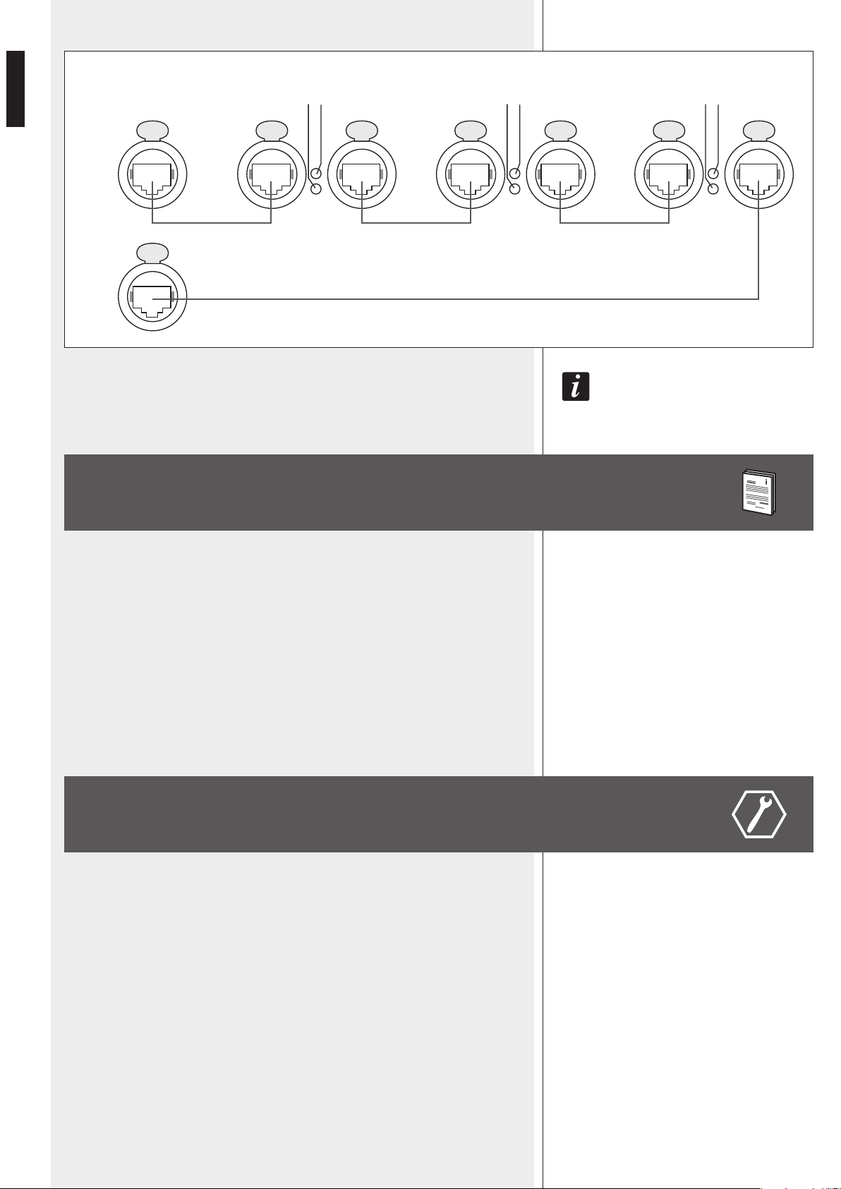
SUBNET PAIRS LINKED IN RINGS
As future option, it will be possible to link subnet
pairs in rings (to verify line integrity).
When using 4 subnet pairs, the max. total quantity of
audio devices that can be connected is 128.
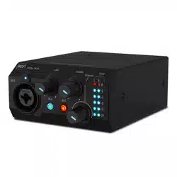
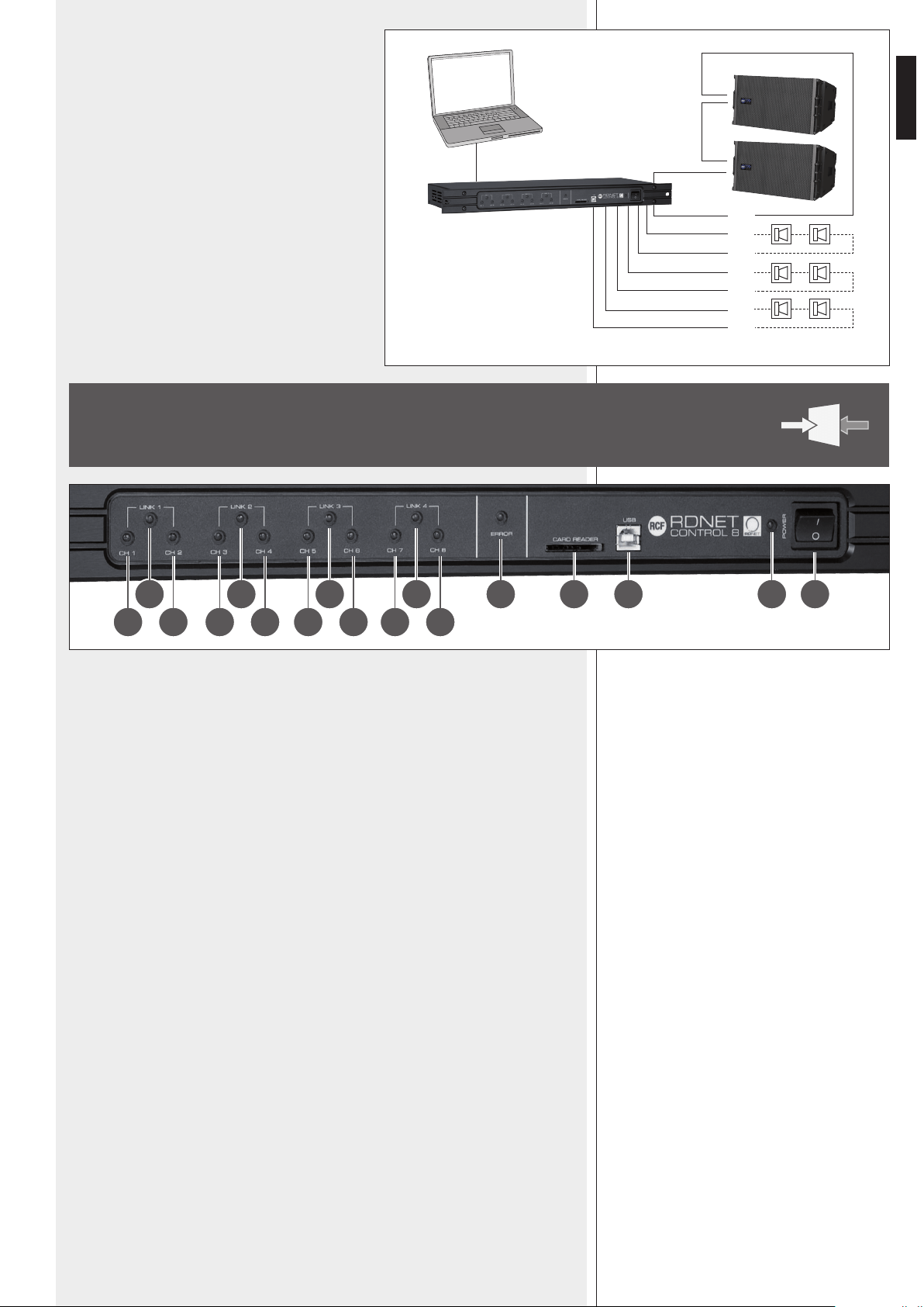
1 CH 1 LED indicating (when flashing) data transmission / reception in the subnet 1.
2 CH 2 LED indicating (when flashing) data transmission / reception in the subnet 2.
3 CH 3 LED indicating (when flashing) data transmission / reception in the subnet 3.
4 CH 4 LED indicating (when flashing) data transmission / reception in the subnet 4.
5 CH 5 LED indicating (when flashing) data transmission / reception in the subnet 5.
6 CH 6 LED indicating (when flashing) data transmission / reception in the subnet 6.
7 CH 7 LED indicating (when flashing) data transmission / reception in the subnet 7.
8 CH 8 LED indicating (when flashing) data transmission / reception in the subnet 8.
9 LINK 1 LED indicating (when lit) that subnets 1 and 2 are linked in a ring.
P LINK 2 LED indicating (when lit) that subnets 3 and 4 are linked in a ring.
{ LINK 3 LED indicating (when lit) that subnets 5 and 6 are linked in a ring.
} LINK 4 LED indicating (when lit) that subnets 7 and 8 are linked in a ring.
q ERROR LED indicating (when lit) an error during data transmission / reception.
w CARD READER slot for an SD (‘Secure Digital’) flash memory.
This slot is not enabled in the current firmware release.
e USB port (type B) for the computer (local) link.
r POWER LED indicating (when lit) that the unit is switched on.
t POWER switch (I:ON, O:OFF).
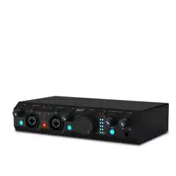
FRONT PANEL
9 10 11 12 13 14 15 1716
1 3 5 72 4 6 8
PC
USB / ETHERNET
RDNET CONTROL 8
EIA RS-485
2
3
4
5
6
7
8
ex.: 4 SUBNET PAIRS LINKED IN RINGS
AUDIO
DEVICES
(max. 32
per subnet)
SUBNET 1
8
ENGLISH
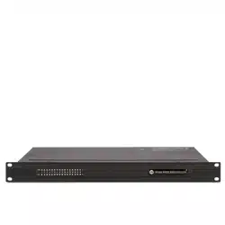
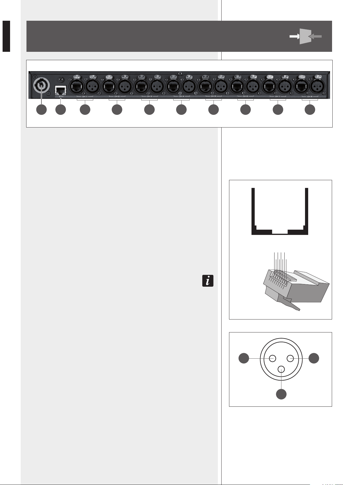
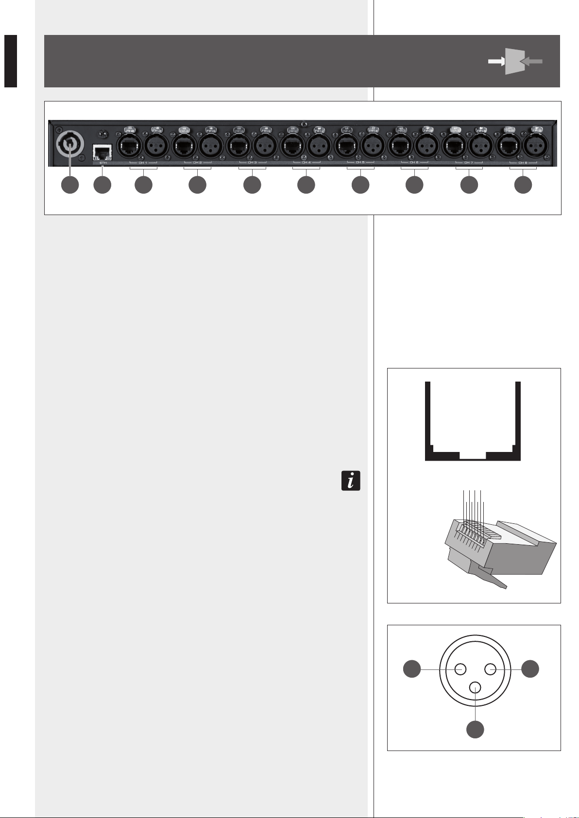
y ‘Powercon’ connector for the power cable.
Operating voltage: 100 ÷ 240 V ac (50 – 60 Hz).
u ETH ETHERNET port (to link a remote computer).
RJ45 CONNECTOR (CAT5 cable):
pin
1- TX+
2- VDD
3- TX–
4- RX+
5- digital ground
6- RX–
7- not used
8- ground
i CH1 Subnet 1 RDNET port, through either an RJ 45 connector (CAT5 cable ) or a
3-pole XLR socket.
Do NoT coNNecT boTh RJ 45 aND XLR coNNecToRs aT The same RDNeT poRT!
RJ 45 CONNECTOR
pin
1 – available for other functions (for example: audio signal +, hot)
2 – available for other functions (for example: audio signal –, cold)
3 – available for other functions (for example: analogue ground)
4 – digital ground
5 – digital ground
6 – available for other functions (for example: power supply)
7 – RS 485 A
8 – RS 485 B
XLR SOCKET
pin
1 – digital ground
2 – RS 485 A
3 – RS 485 B
REAR PANEL
18 19 20 2422 2621 2523 27
XLR SOCKET
3
12
RJ 45 SOCKET
|1|2 |3 |4 |5 |6 |7 |8 |
RJ 45 PLUG
8 46 2
7 35 1
9
ENGLISH
o CH2 Subnet 2 RDNET port, through either an RJ 45 connector (CAT5 cable)
or a 3-pole XLR socket (see i).
p CH3 Subnet 3 RDNET port, through either an RJ 45 connector (CAT5 cable)
or a 3-pole XLR socket (see i).
[ CH4 Subnet 4 RDNET port, through either an RJ 45 connector (CAT5 cable)
or a 3-pole XLR socket (see i).
] CH5 Subnet 5 RDNET port, through either an RJ 45 connector (CAT5 cable)
or a 3-pole XLR socket (see i).
A CH6 Subnet 6 RDNET port, through either an RJ 45 connector (CAT5 cable)
or a 3-pole XLR socket (see i).
S CH7 Subnet 7 RDNET port, through either an RJ 45 connector (CAT5 cable)
or a 3-pole XLR socket (see i).
D CH8 Subnet 8 RDNET port, through either an RJ 45 connector (CAT5 cable)
or a 3-pole XLR socket (see i).
Each of the 8 available RDNET ports of the RDNET CONTROL 8 unit can be connected
to max. 32 compatible audio devices (linked in ‘daisy-chain’).
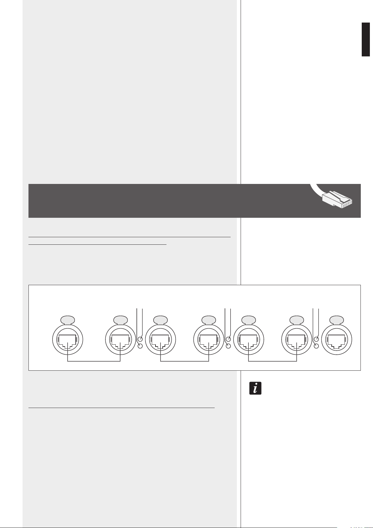
Example: the RDNET CONTROL 8 port 1 is connected to the DATA IN input of a RCF
TTL-55A loudspeaker, of which DATA LINK parallel output is linked to the input of the
following TTL55-A loudspeaker.
IN The eXampLe above, [n] Is a NumbeR fRom 3 To 32 (maX. quaNTITy of auDIo DevIces ThaT caN be
coNNecTeD To a subNeT).
The total CAT 5 cable length of a subnet cannot exceed 900 metres (c. 2950 feet).
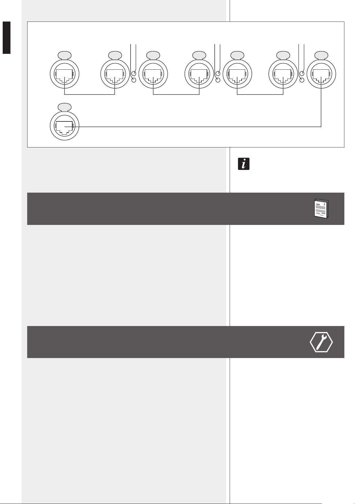
As future option, it will be possible to link subnet pairs in rings (to verify line integrity).
For instance: the RDNET CONTROL 8 port 1 is connected to the DATA IN input of a
RCF TTL55A loudspeaker, of which DATA LINK parallel output is linked the input of the
following TTL55A loudspeaker. The DATA LINK output of the last TTL55A loudspeaker of
the line is connected the RDNET CONTROL 8 port 2.
SUBNET CONNECTION
RDNET
CONTROL 8
TTL55-A [1] TTL55-A [2] TTL55-A [n]
DATA IN DATA IN DATA INDATA LINK DATA LINK DATA LINK
CH 1
ACTIVE
LINK
ACTIVE
LINK
ACTIVE
LINK
10
ENGLISH
LINK 1 9 , LINK 2 P , LINK 3 { e LINK 4 } fRoNT paNeL LeDs INDIcaTe The RINg
coNNecTIoN of The RespecTIve paIR of subNeTs.
The RDNET software is protected by international copyright laws and is to be used to
configure the RCF RDNET system only.
It is not allowed to modify or change or try to decompile this software.
In no event shall RCF S.p.A. be liable to end-users for any damage whatsoever, including
but not limited to financial damages for loss of business profits or business information
due to the software use or inability to use this product.
The foregoing provision is effective even if RCF S.p.A. has been advised of the possibility
of such damages.
Even if the SOFTWARE has any material, verifiable and reproducible program errors, RCF
S.p.A. shall have no obligation to modify such errors.
Minimum requirement: a PC with Microsoft ‘Windows® XP’, ‘Vista’ or ‘7’ operating
system, having an available USB port and / or ETHERNET.
Before installing a new software release, it is necessary to remove the previous version (if
installed) by running Start > Programs > RCF Group > RDNet > Uninstall and (in
case) disconnect the USB cable between the computer and the RDNET CONTROL 8 unit.
Run setup.exe (inside the ‘setup’ folder) to start the software installation.
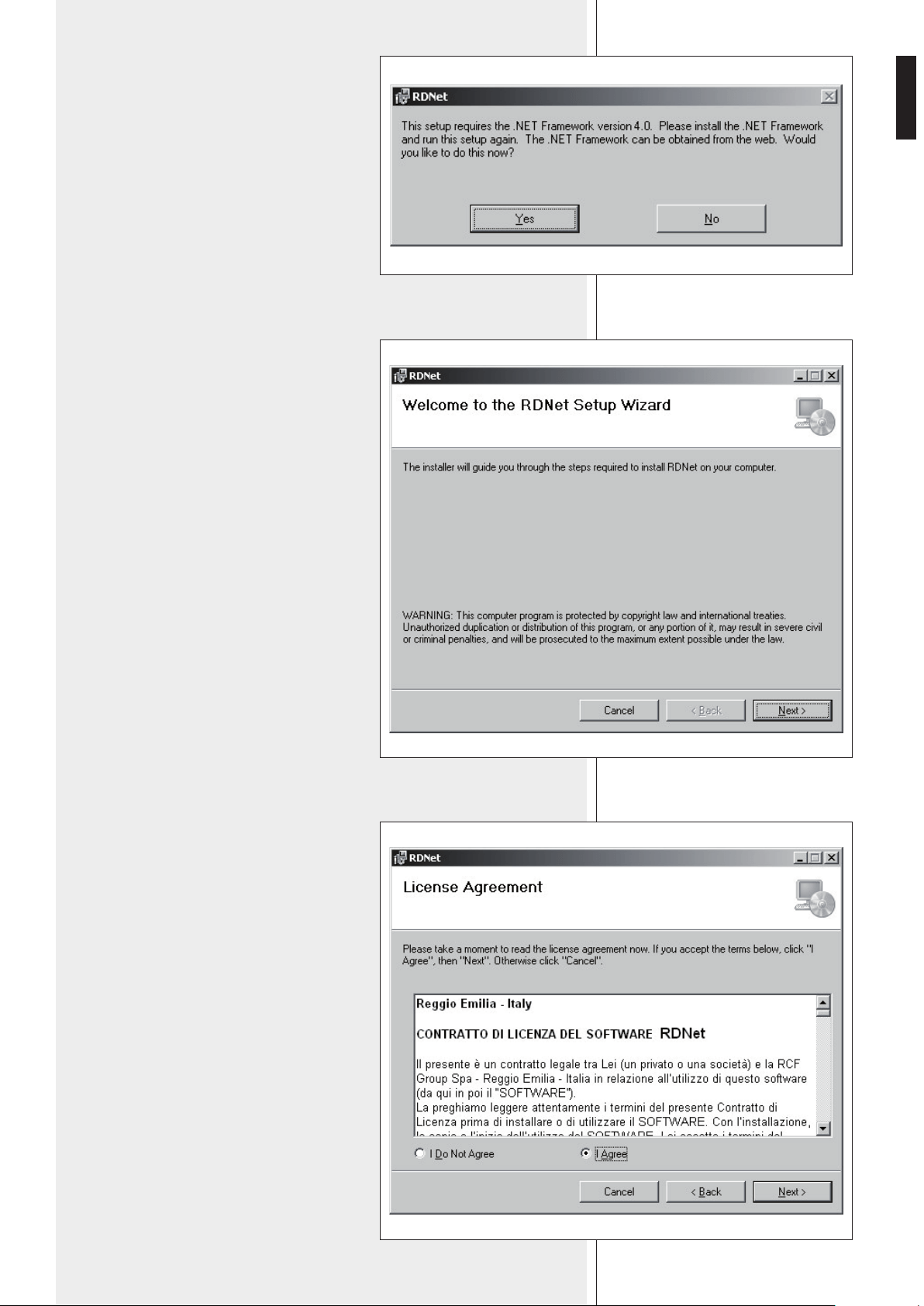
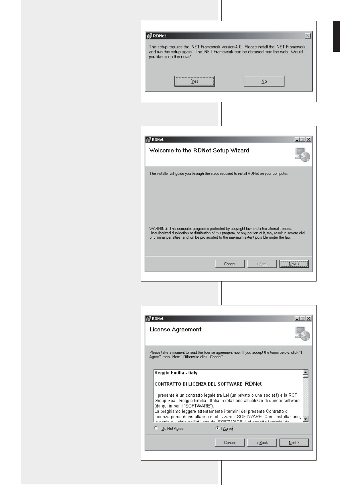
If the installed PC software does not include the release 4.0 of MS “.NET Framework”
(necessary to install the RDNET software), it will be show the request for downloading
from the web (for free).
NOTES ABOUT THE RDNET SOFTWARE
RDNET
CONTROL 8
TTL55-A [1] TTL55-A [2] TTL55-A [n]
DATA IN DATA IN DATA INDATA LINK DATA LINK DATA LINK
CH 1
CH 2
ACTIVE
LINK
ACTIVE
LINK
ACTIVE
LINK
RDNET SOFTWARE INSTALLATION
11
ENGLISH
If internet is available, click the YES button
to open the web page where it is possible
to download the last release of the ‘.NET
Framework’ software, then install it.
Read the license agreement.
Click ‘I Agree’ to accept and proceed with the
software installation.
Click the NEXT > button to proceed.
If ‘.NET Framework 4.0’ has been previously
installed, the RDNET software wizard starts.
Click the NEXT > button to proceed.
12
ENGLISH
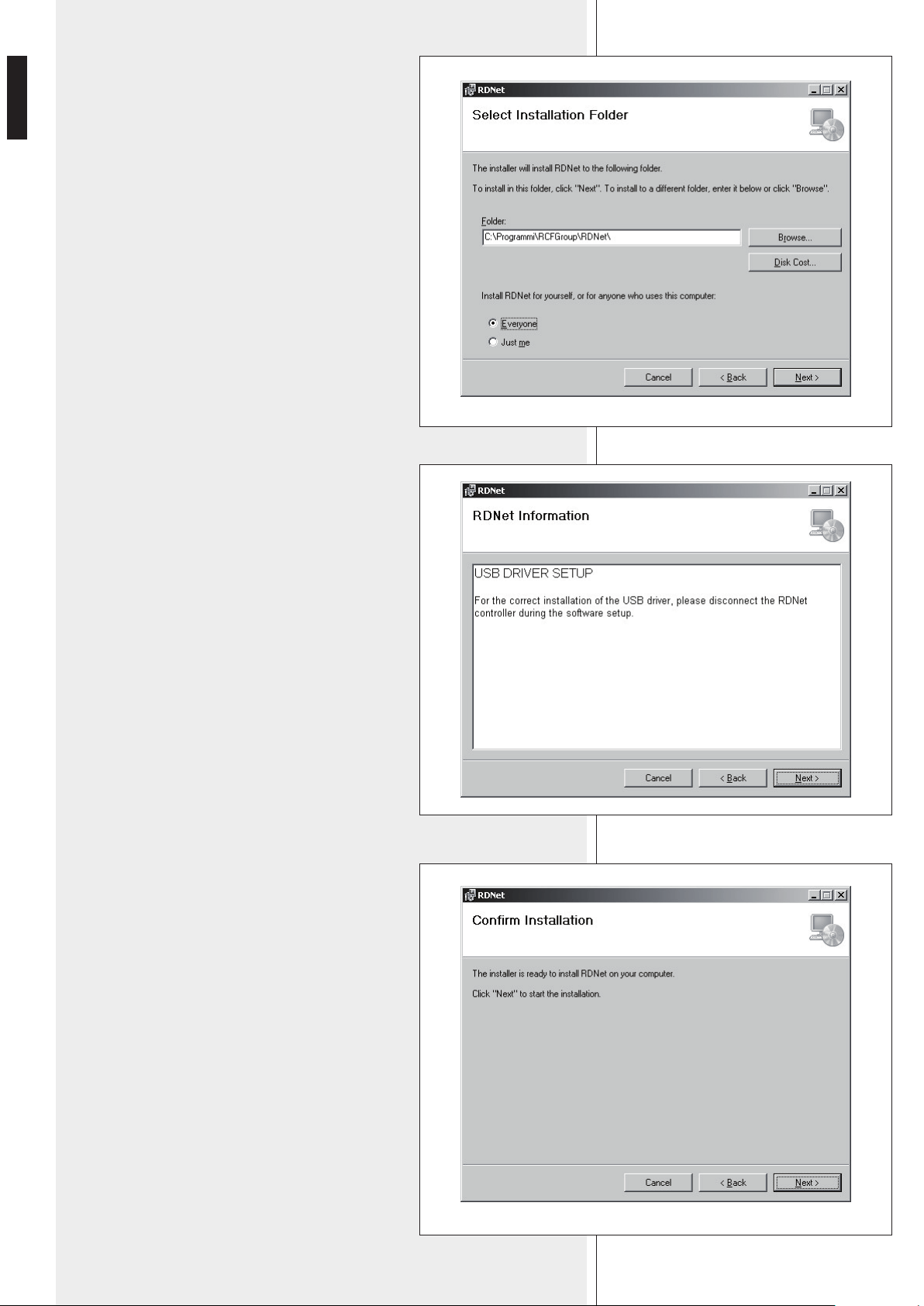
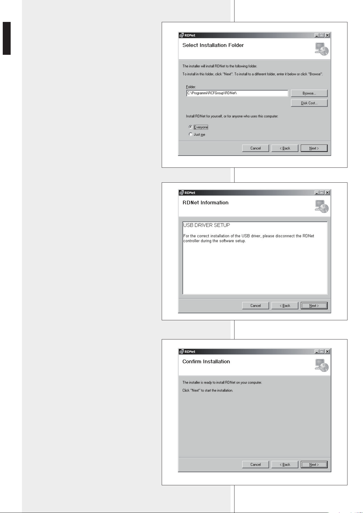
It is now possible to change the installation folder
(directory) of the RDNET software (or keep the
default path).
Choose if the software can be used by ‘Everyone’
or ‘Just me’.
Click the NEXT > button to proceed.
The wizard reminds you that it is necessary to
disconnect the USB cable between the computer
and the RDNET CONTROL 8 unit in order to install
USB drivers properly.
Check if the USB cable is actually disconnected
before proceeding.
Then, it is required the installation confirmation.
If you are sure, click the NEXT > button to
proceed and start the installation.
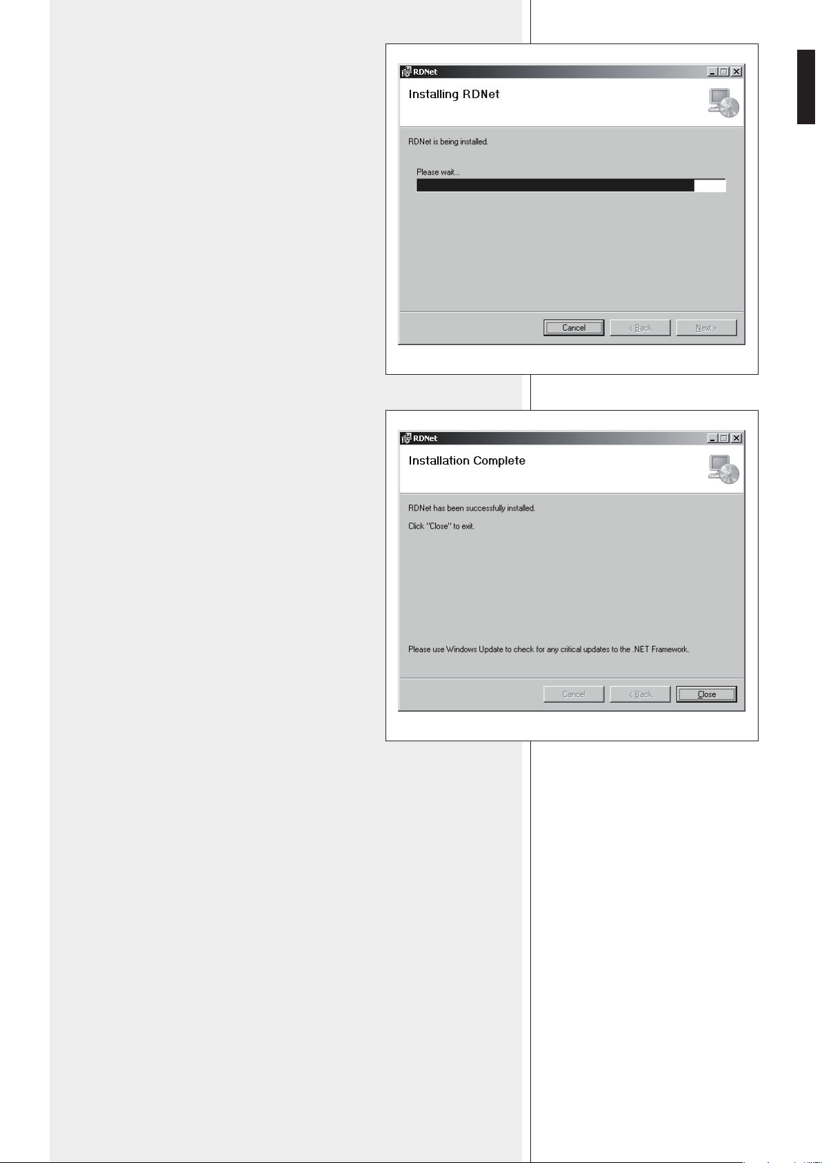
Await the installation is complete.

13
ENGLISH
While waiting, the installation progress bar is
shown.
As soon as the installation ends (no error), the
‘Installation Complete’ window will appear.
Click the CLOSE button to exit.
Connect the USB cable or ETHERNET between the
computer and the RDNET CONTROL 8 unit before
running the software.
14
ENGLISH
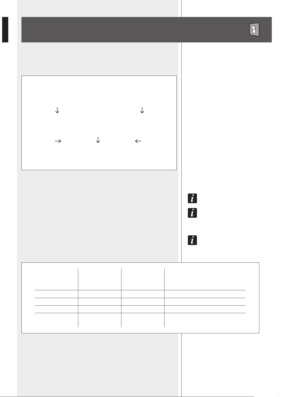
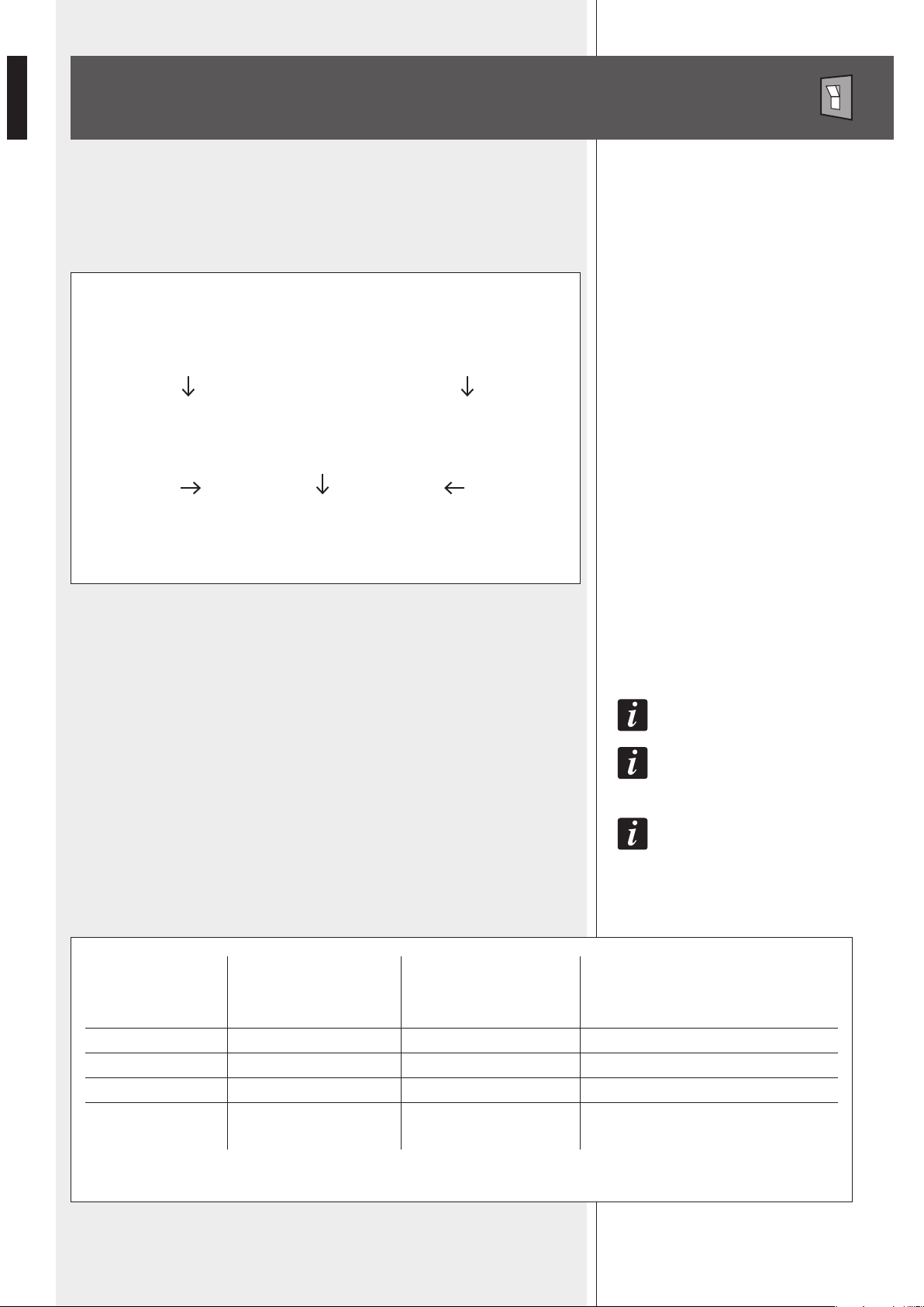
Loudspeaker not linked to RDNET
(device not listed, the ‘LINK’ LED is off)
The BYPASS switch is pressed ?
NO YES
The keyboard configuration is applied The loudspeaker loads its stored preset
The ‘BYPASS’ LED is off The ‘BYPASS’ LED is lit
Loudspeaker linked to RDNET
(device listed, the ‘LINK’ LED is lit)
All data concerning the selected preset and the operating mode are sent to the computer.
IT Is possIbLe To eDIT aLL paRameTeRs aND sToRe Them IN LouDspeakeRs by usINg The pc sofTwaRe.
If The RDNeT NeT Is DIscoNNecTeD, ThIs pRoceDuRe wILL ResTaRT fRom The begINNINg.
fILTeR DaTa caNNoT be seNT To LouDspeakeRs fRom pc. The oNLy way To kNow If LouDspeakeR DaTa
aRe IDeNTIcaL To The pc sofTwaRe seTTINgs Is To check ThaT The LouDspeakeR (oR aNy oTheR DevIce) Is
syNchRoNIzeD.
If The sofTwaRe Is ‘oNLINe’, LouDspeakeR maIN seTTINgs aRe RemoTe coNTRoLLeD ThRough RDNeT
NeTwoRk. If The sofTwaRe Is ‘offLINe’, LouDspeakeR maIN seTTINgs DepeND oN ITs INpuT paNeL bypass
swITch (ThaT RecaLLs The LasT saveD coNfIguRaTIoN). see The foLLowINg TabLe.
In every RDNET compatible loudspeaker, when pressing the BYPASS switch, it is possible
to recall a previously stored preset and disable the loudspeaker keyboard.
The following flowchart indicates the BYPASS function:
LOUDSPEAKER BYPASS SWITCH
RDNET software
(network status)
offline
offline
online
online
Loudspeaker
BYPASS switch
OFF
ON
OFF
ON
Loudspeaker
BYPASS LED
OFF
ON
OFF
ON
Loudspeaker
configuration
According to the loudspeaker front panel
Last saved configuration
Settings through RDNET network
Settings through RDNET network
15
ENGLISH
as sooN as The RDNeT coNTRoL 8 uNIT Is TuRNeD oN, aLL DevIces wILL be LIsTeD aND cycLIcaLLy
scaNNeD (‘poLLINg’).
Every listed device confirms its operation by turning its ‘LINK’ LED on.
10 times a second, each device is checked in a single daisy-chain and (when required) the
current status is sent to the PC software.
Run the software (in Windows: Start > Programs > RCF Group > RDNet > RDNet):
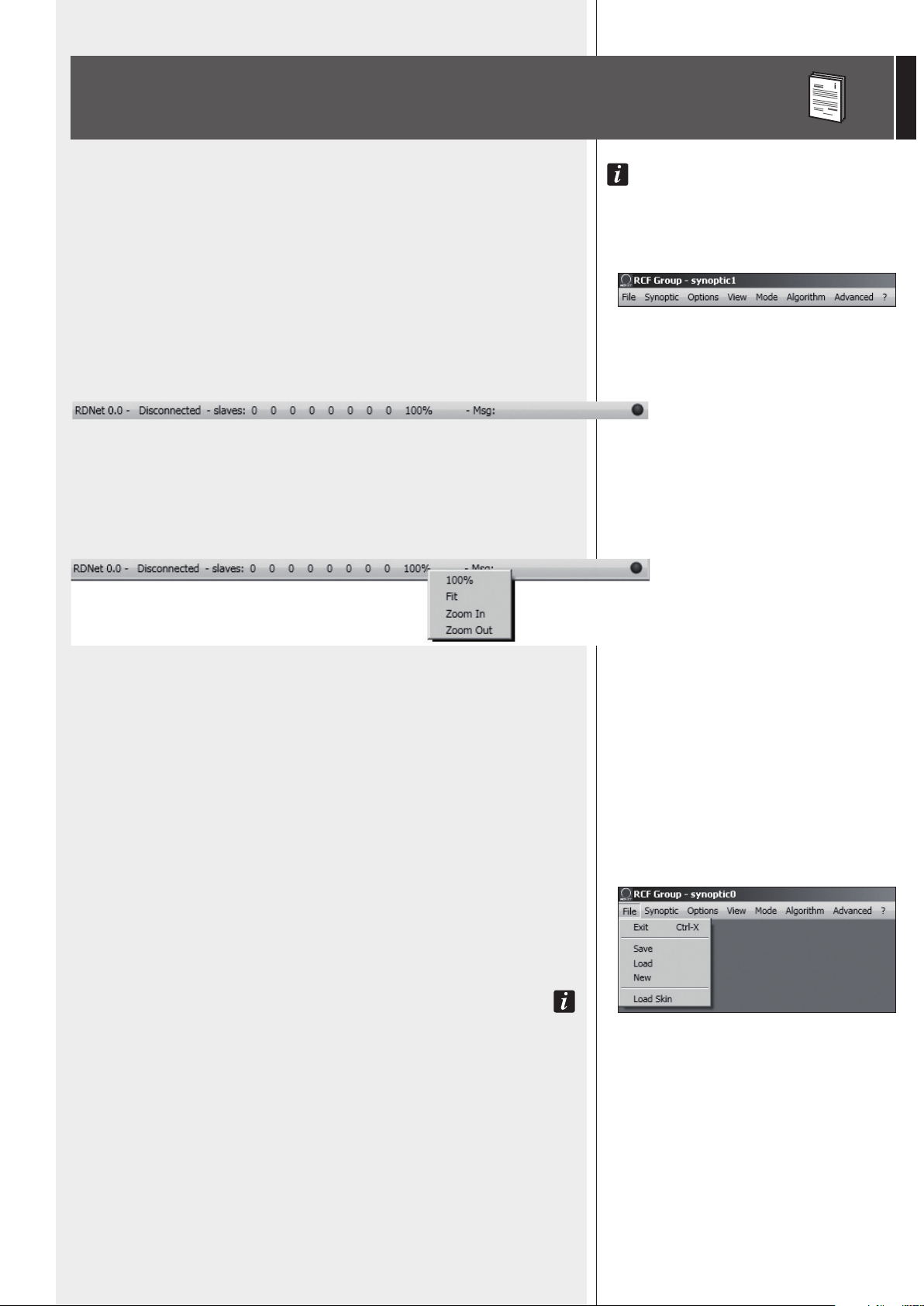
it appears the main window with 8 menus:
‘File’, ‘Synoptic’, ‘Options’, ‘View’, ‘Mode’, ‘Algorithm’, ‘Advanced’, ‘?’.
RDNET SOFTWARE (release 1.0.0.68)
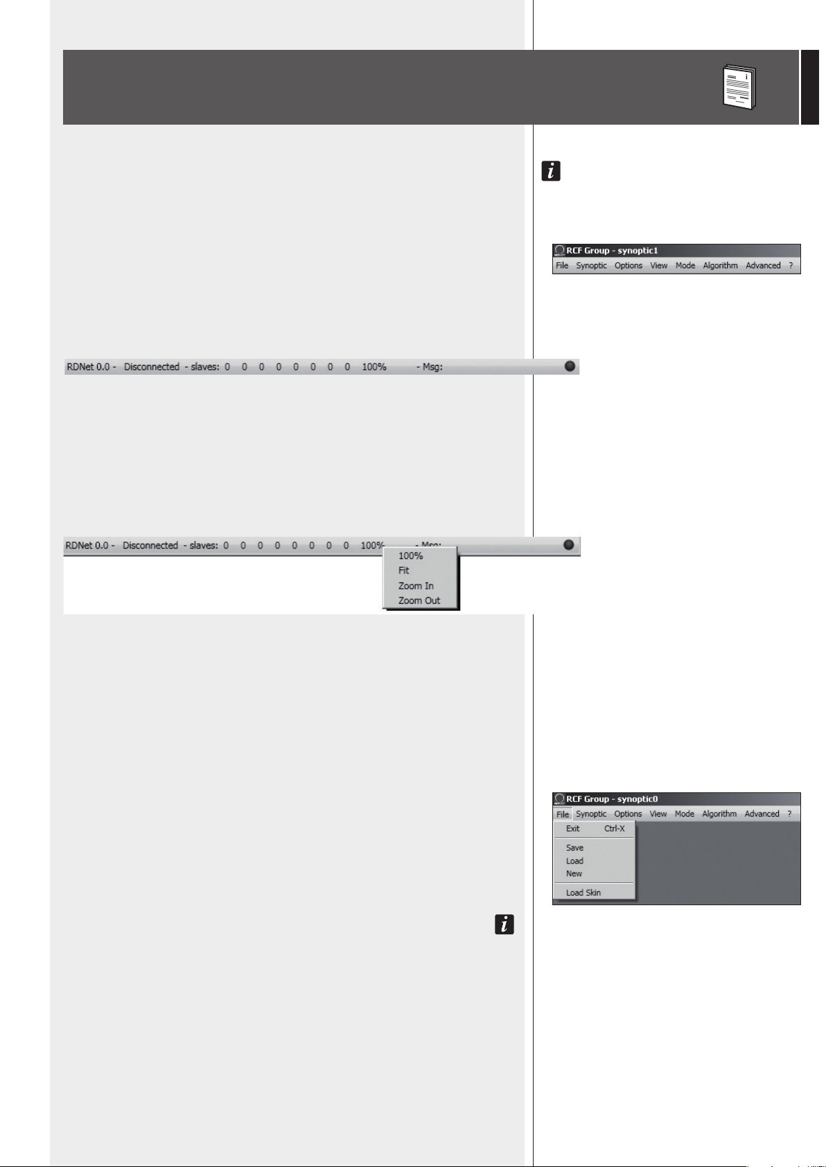
STATUS BAR
The status bar (main window bottom) includes:
- The connection status (Connected / Disconnected)
- Devices found in each of the 8 lines (slaves: n n n n n n n n)
- Synoptic zoom (default: 100%)
- A LED type indicator that flashes when the PC is connected.
Right-click the zoom value to visualize the respective 4 synoptic zoom options:
100%: it resets the default zoom
Fit:
it automatically fits the zoom, according to the number and positions of the present objects
Zoom In: 10% zoom in
Zoom Out: 10% zoom out.
It is also possible to adjust the zoom by pressing and holding the computer keyboard Ctrl
key and turning the mouse scroll wheel at the same time.
FILE
Exit: RDNET software quit.
Save: it saves the current configuration as .rds file (groups and equalizations included).
Load: it loads a configuration previously saved as .rds file .
New: new configuration.
Load aND New seLecTIoNs DeLeTe The cuRReNT coNfIguRaTIoN!
Load Skin: it loads a software skin (.xaml file).
16
ENGLISH
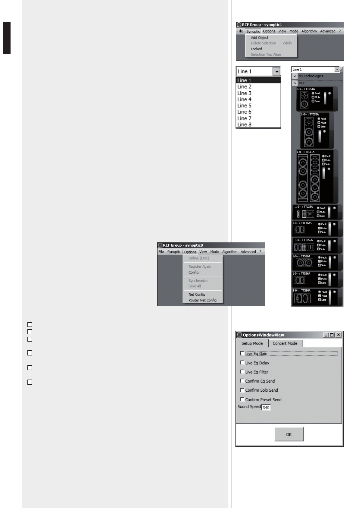
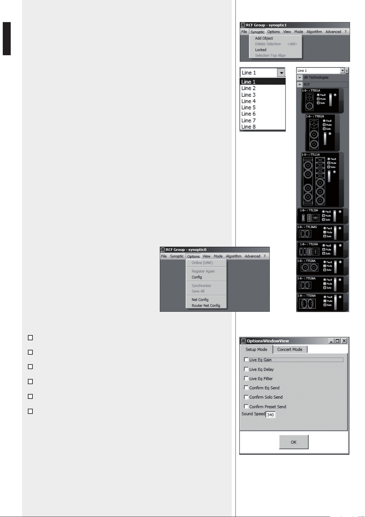
OPTIONS
Online: it enables the link between the PC and the
RDNET CONTROL 8 unit.
Register Again: reconfiguration and digital re-
addressing of all audio devices connected to RDNET
(to be used in case of communication errors).
Config: 2 protection modes: ‘Setup’ and ‘Concert’.
In both it is possible to enable (or disable for safety
reasons) one or more of the 6 listed functions and set
the current sound speed:
Live Eq Gain: it enables the real-time GAIN setting (in the equalization window).
Live Eq Delay: it enables the real-time DELAY setting (in the equalization window).
Live Eq Filter: it enables the real-time equalization.
Confirm Eq Send: it enables the EQ confirmation request when clicking the SEND
button.
Confirm Solo Send: it enables the confirmation request when activating the
‘SOLO’ function (only one loudspeaker turned on at a time).
Confirm Preset Send: it enables the confirmation request when sending a preset
to a loudspeakers (e.g. TTL55A: field and cluster loudspeaker number settings).
Sound Speed: current sound speed setting (the sound speed depends on the air
temperature), indicated in metres per second (340 m/s a 15°C / 59°F, 343 m/s at
20°C / 68°F, 346 m/s at 25°C / 77°F, 349 m/s at 30°C / 86°F).
SYNOPTIC
Add Object: it opens a window where it is possible to add one or more objects
(among all available, which correspond to different loudspeakers, e.g. RCF TTL55A)
to the synoptic.
First choose the line (to which the loudspeaker is linked), then the loudspeaker
(double-click the respective object): the object is added to the synoptic.
Delete Selection: it deletes (after confirmation) the selected object.
Locked: it locks all object positions in the synoptic (to be selected as soon as the
synoptic is complete).
Selection Top Align: it makes all selected objects aligned at the same synoptic level
(the same of the highest object).

17
ENGLISH
Synchronize: it aligns all parameter values of all loudspeakers that are linked to RDNET
to the current software configuration.
Save All: it stores all configurations to all loudspeaker memories.
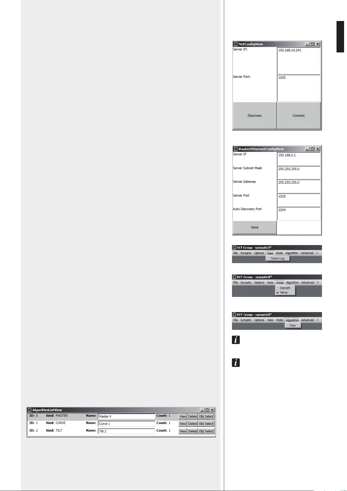
Net Config: it opens the ‘NetConfigView’ window, in which it is possible to connect the
RDNET CONTROL 8 unit via Ethernet after setting both the IP address (‘Server IP’) and
the port (‘Server Port’).
Click ‘Discovery’ to search IP addresses.
Click ‘Connect’ to enable Ethernet.
Router Net Config: it opens a window where it is possible to send (by clicking ‘Send’)
the ‘Server IP’, the ‘Server Subnet Mask’, the ‘Server Gateway’ and the ‘Server Port’ to the
RDNET CONTROL 8 unit.
Auto Discovery Port: setting of the port that allows to find the ‘master’ unit.
VIEW
Comm Log: log view.
MODE
Selection of the protection mode between ‘Concert’ and ‘Setup’, settable in the
Options > Config menu.
ALGORITHM (for expert users only)
aN aLgoRIThm INcLuDes commoN seTTINgs foR moRe obJecTs.
aN obJecT (coRRespoNDINg To a LouDspeakeR) caN be assIgNeD To moRe aLgoRIThms aND, TheRefoRe,
affecTeD To aLL RespecTIve seTTINgs.
NoTe: be caRefuL NoT To coNfuse aLgoRIThms wITh gRoups (fuNcTIoN eXpLaINeD IN The foLLowINg ‘assIgN
aN obJecT To a gRoup’ maNuaL secTIoN)!
eveRy obJecT caN beLoNg To a sINgLe gRoup oNLy.
Click Algorithm > View to open the ‘AlgorithmListView’ window that shows the list of
created and available algorithms.
18
ENGLISH
The assIgNmeNT of aN obJecT To aN aLgoRIThm (aND ITs cReaTIoN) caN be maDe fRom The obJecT ITseLf
(see The ‘assIgN aN obJecT To aN aLgoRIThm’ maNuaL secTIoN).
ID: it indicates the progressive number (starting from 0) of current algorithms.
Kind: algorithm kind.
3 kinds: MASTER, CURVE and TILT (their functions are described here below).
Name: algorithm name (freely assignable).
Count: number indication of all objects currently assigned to that algorithm.
View: it opens the window including the algorithm parameters.
Delete: it deletes he algorithm (pay attention: all its settings will be lost!)
Obj Select: it makes the information of all objects assigned to that algorithm lined with red.
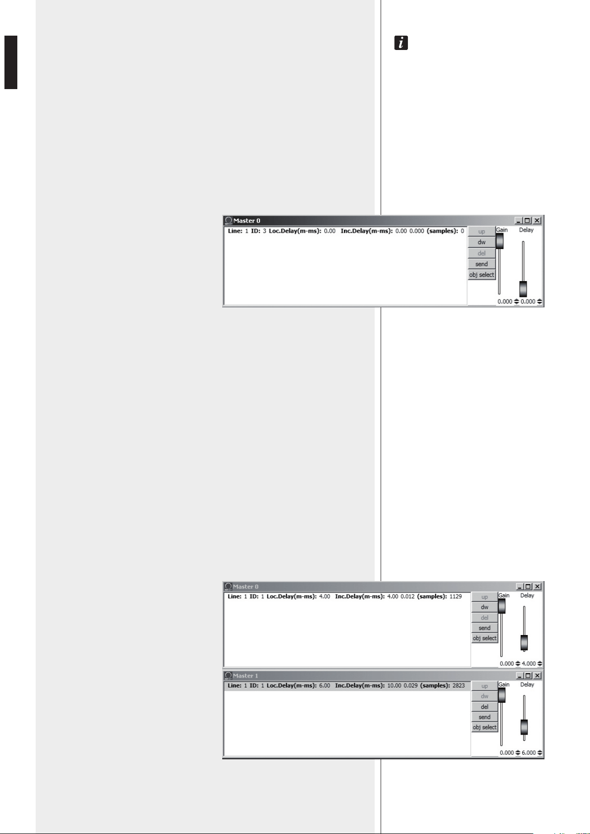
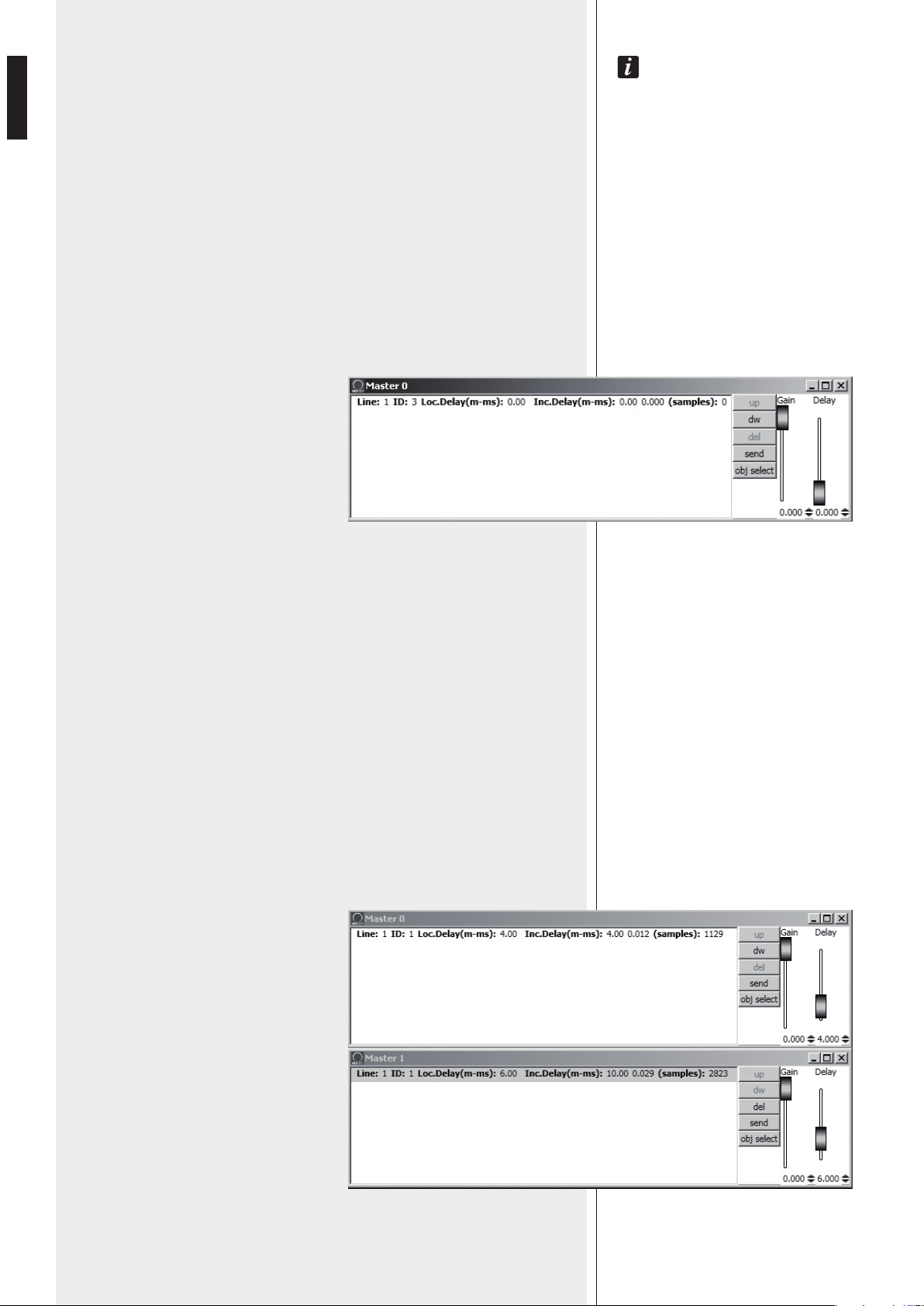
Click View of a MASTER algorithm to see its respective setting window:
On the left there is the object list (objects can be identified by ‘Line’ and ‘ID’
numbers).
Loc.Delay: audio signal delay value (indicated in the equivalent distance in metres,
max. 20 metres) set by the algorithm Delay control.
Inc.Delay: audio signal total delay, which is the sum of all delays of all algorithms
upstream (with lower ID numbers, to which the object has already been assigned)
and the delay of the current selected algorithm.
Its value is indicated in the equivalent distance in metres, in seconds (time) and
samples.
The maximum total delay cannot exceed 21.25 m (equivalent distance),
corresponding to 6000 samples.
EXAMPLE
An object has been assigned to 2 MASTER algorithms: in the first (MASTER 0) the
delay (Loc.Delay) is set to 4 metres, in the second (MASTER 1) the delay is 6 metres.
The total delay (Inc.Delay) indicated in the second algorithm (MASTER 1) is 10
metres (4 m + 6 m).
19
ENGLISH
BUTTONS
up: it moves up (one location) the selected line (corresponding to an object), function
that is useful to sort more lines.
dw: it moves down (one location) the selected line (corresponding to an object), function
that is useful to sort more lines.
del: it deletes the selected line (corresponding to an object), attention: the object will no
longer be affected by the algorithm settings!
send: it sends the algorithm settings to the loudspeaker corresponding to the
selected object.
obj select: it shows all the objects assigned to that algorithm by lining the respective
information with red.
CURSORS
Gain: audio signal gain setting from 0 to –20 dB (20 dB attenuation).
Delay: audio signal delay setting.
USE EXAMPLE
It is possible to get common settings for two front line-arrays (made of loudspeakers) of a
stage, by using MASTER algorithms, for instance:
MASTER: common settings for all loudspeakers (both left and right channels)
LEFT: common settings for all left loudspeakers only
RIGHT: common settings for all right loudspeakers only
FAR: common settings for all far-field loudspeakers only
NEAR: common settings for all near-field loudspeakers only.
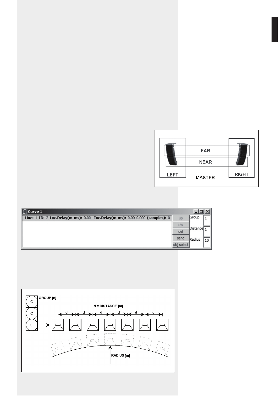
Click View of a CURVE algorithm to see its respective setting window:
The CURVE algorithm can be useful when using subwoofers (loudspeakers designed for
very low frequencies), placed on the ground at the centre under the stage, to improve
their efficiency by creating a ‘virtual curve’ of subwoofer positions.
20
ENGLISH
The 3 parameters (to be set) in the window on the right:
Group: quantity of subwoofers grouped at the same position
Distance: distance (in metres) between a subwoofer group axis and those adjacent
Radius: curve radius (in metres).
In each line (corresponding to an object):
Loc.Delay: audio signal delay value (indicated in the equivalent distance in metres, max.
20 metres) that depends on the 3 parameter settings
Inc.Delay: audio signal total delay (the sum of all delays, considering also all algorithms
upstream of the selected one).
About the buttons up, dw, del, send, obj select, please refer to the previous MASTER
algorithm.
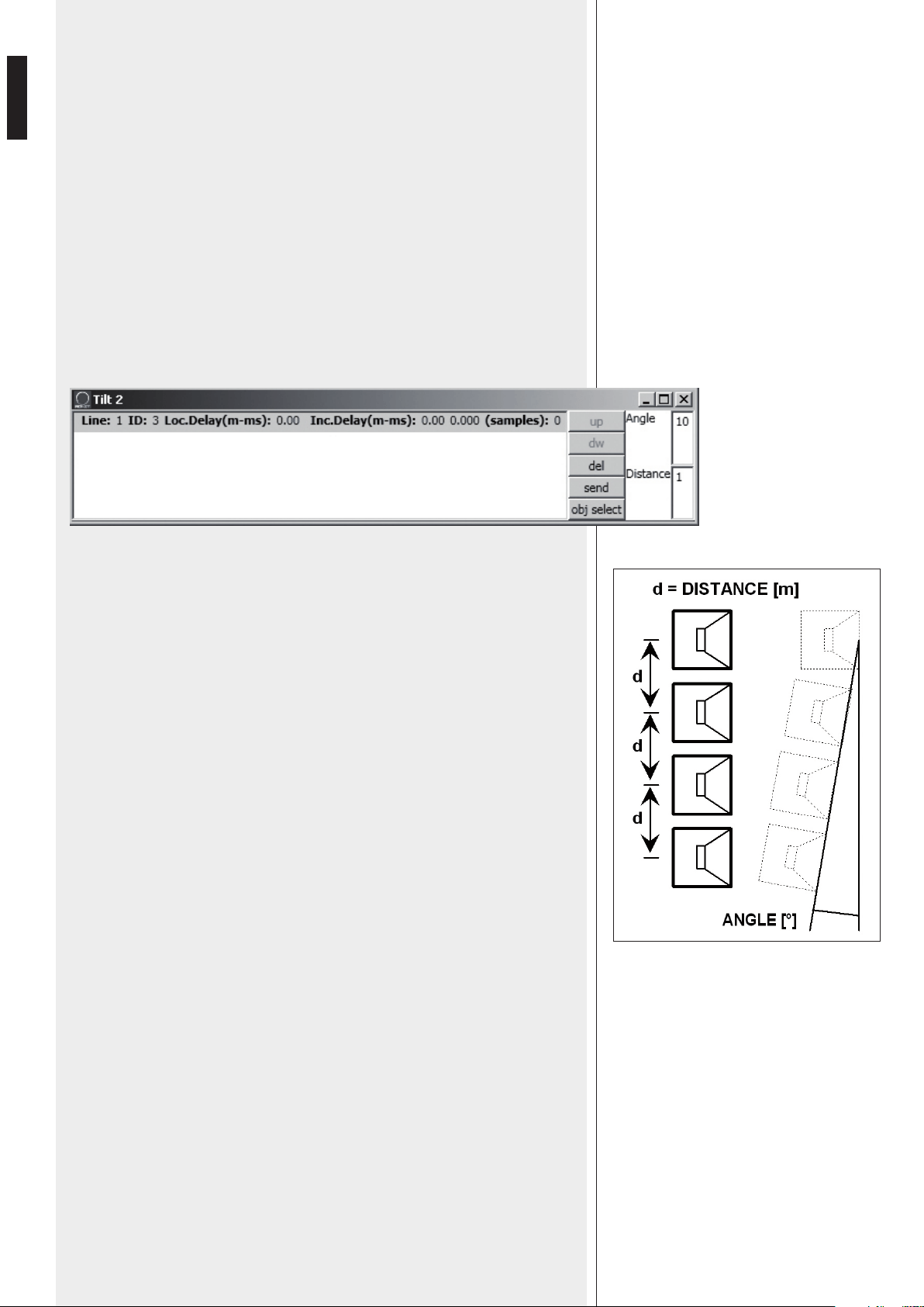
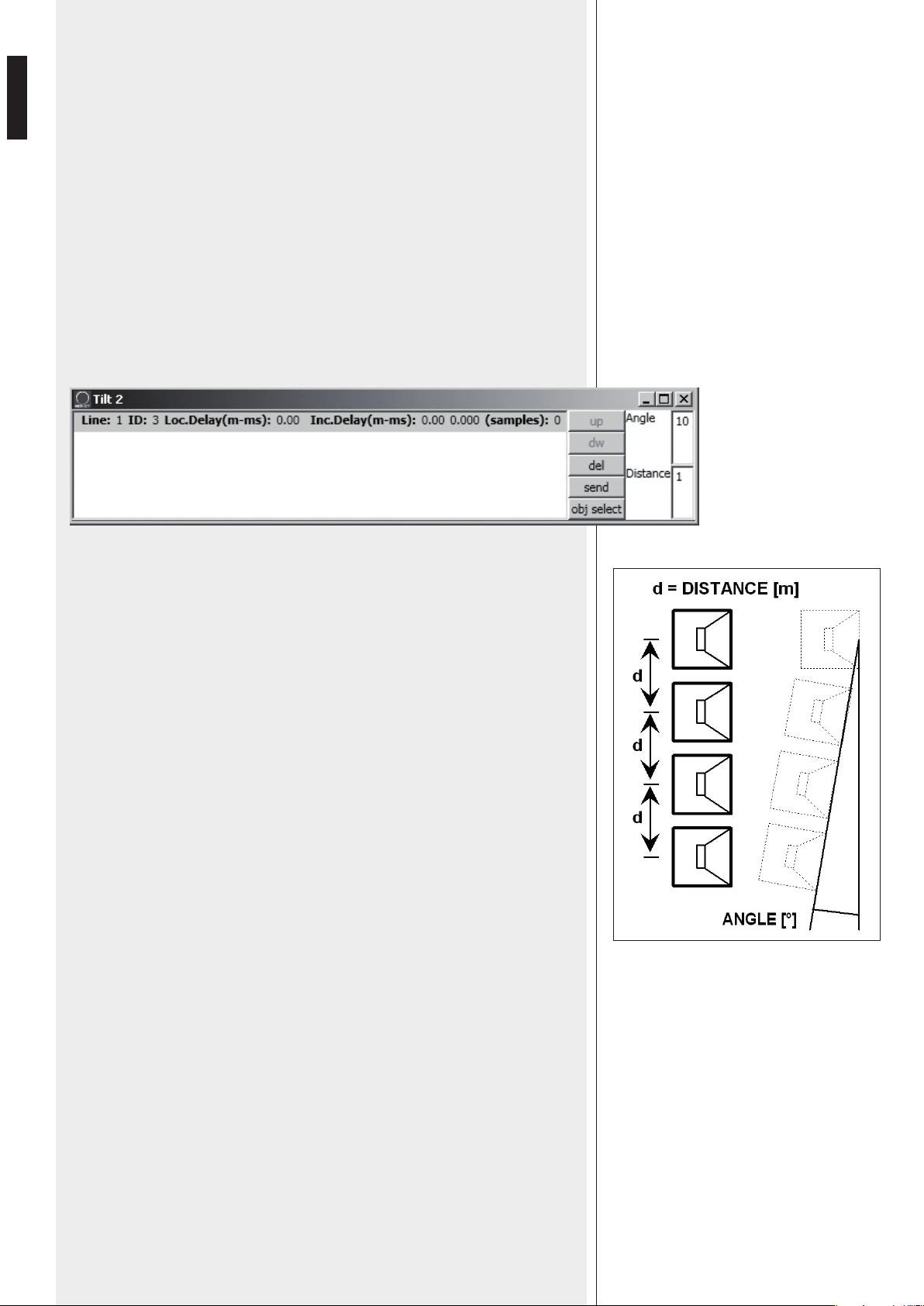
Click View of a TILT algorithm to see its respective setting window:
The TILT algorithm can be useful when using subwoofers in a suspended cluster to get a
better near-field coverage, by creating a sort of virtual vertical tilt of subwoofers.
The 2 parameters (to be set) in the window on the right:
Angle: vertical tilt angle (degrees)
Distance: distance (in metres) between a subwoofer axis and those adjacent.
In each line (corresponding to an object):
Loc.Delay: audio signal delay value (indicated in the equivalent distance in metres, max.
20 metres) that depends on the 2 parameter settings
Inc.Delay: audio signal total delay (the sum of all delays, considering also all algorithms
upstream of the selected one).
About the buttons up, dw, del, send, obj select, please refer to the previous MASTER
algorithm.
21
ENGLISH
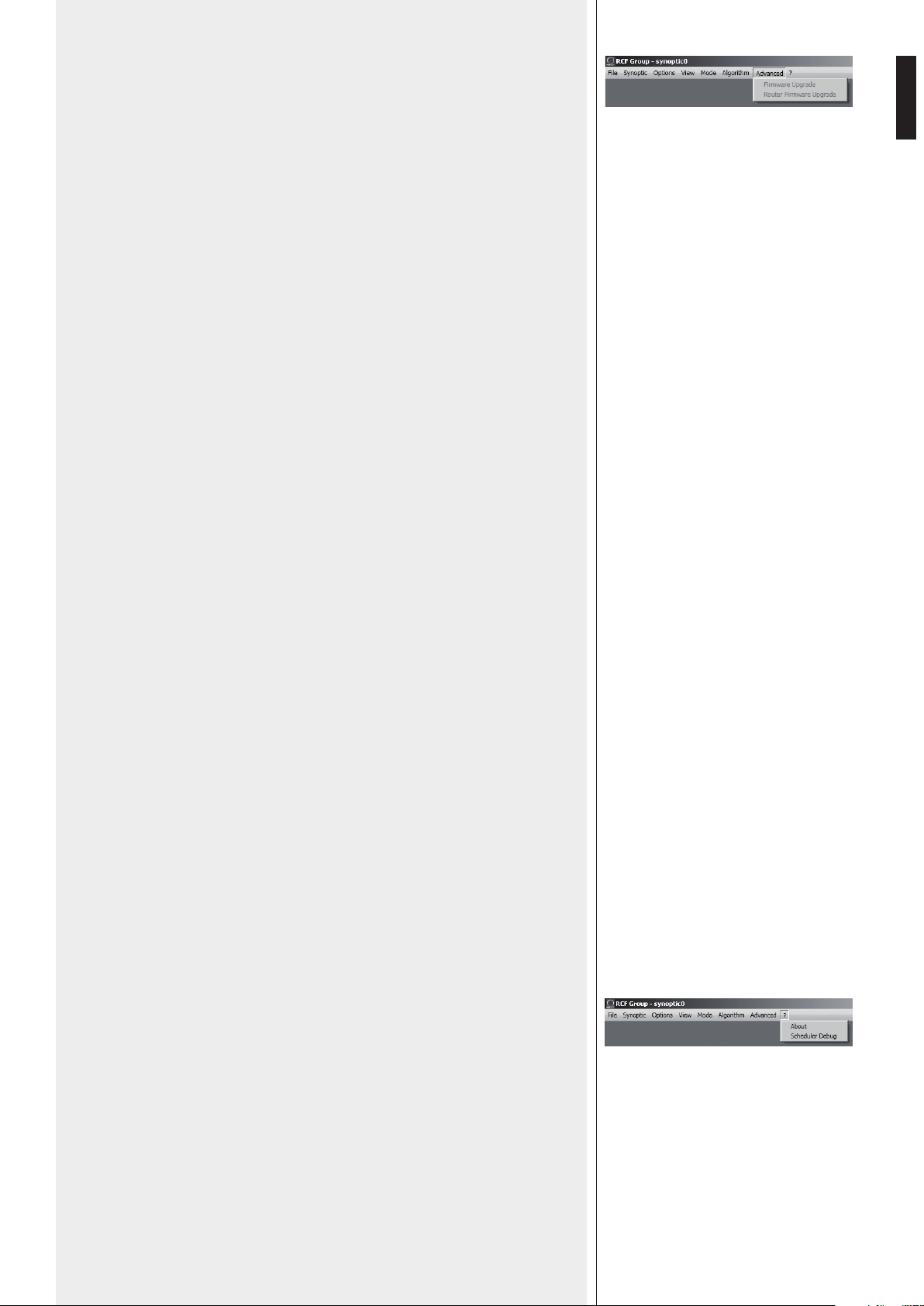
ADVANCED
Firmware Upgrade: loudspeaker (or any other audio device) firmware upgrade.
1. Link the RDNET CONTROL 8 unit to the computer through the USB cable or
ETHERNET.
Turn the RDNET CONTROL 8 unit on without connecting any loudspeaker and wait
until LEDs stop flashing (after c.10-15 seconds).
2. Link the ‘DATA INPUT’ of the only loudspeaker that needs to be upgraded to the
CH1 i connector of the RDNET CONTROL 8 unit (and disconnect all the other
loudspeakers).
3. Turn the loudspeaker on wait until its ‘STATUS’ LED stops flashing.
4. In the software home page, select:
ADVANCED > Firmware Upgrade.
5. Select the file concerning a new specific firmware for that loudspeaker.
6. Click YES on ‘Send to object 0?’ request.
7. Await until the progress bar indicates the installation end, then the CH1 LED will stop
flashing and the loudspeaker will automatically reboot.
8. Wait for the loudspeaker reboot (at the end, its ‘STATUS’ LED stops flashing).
Now the upgrade is complete.
9. Return to the point 2 for a new loudspeaker firmware upgrade.
10. As soon as the firmware upgrade is applied to all loudspeakers, these can be
linked in daisy-chain to RDNET and all the system can be managed by the RDNET
CONTROL 8 unit.
Router Firmware Upgrade: RDNET CONTROL 8 unit firmware upgrade.
1. Link the RDNET CONTROL 8 unit to the computer through the USB cable and turn it
on without connecting any loudspeaker.
2. Wait until its front panel LEDs stop flashing (after c.10-15 seconds).
3. In the software home page, select ADVANCED > Router Firmware Upgrade to
open the respective window, then click ‘LOAD’ and choose the ‘CONTROL8.RDU’ file.
4. The download automatically begins. A new window appears reminding you to
disconnect the USB cable and then reconnect it later. Click OK when complete.
5. Await until the progress bar indicates the installation end, then disconnect the USB
cable and reconnect it later. The RDNET CONTROL 8 unit will automatically reboot.
‘?’ MENU
About: it opens a window indicating the current software release.
Scheduler Debug: it shows found errors (if any).

22
ENGLISH
SYNOPTIC
When online, the RDNET CONTROL 8 unit sequentially scans all audio devices, which
are automatically assigned to digital addresses.
The software synoptic is compared to the real settings and any difference is pointed out:
the loudspeaker objects (or of any other audio device) shown in the software without
being really present in the net have their Fault indicator lit, while for other objects
there is a comparison between software and real data: if differences are found, a yellow
exclamation mark will be shown in the top left-hand corner of objects.
Loudspeakers linked to the net are automatically added to the software synoptic,
therefore the software shows an object per each loudspeaker (or any other audio device)
that has been found.
When offline, it is possible to add objects through the ‘Synoptic > Add Object’ menu (by
double-clicking each object that needs to be added).
To uNdersTaNd characTerisTics aNd fuNcTioNs of aLL Loudspeakers (or audio devices),
aLways refer To Their respecTive user maNuaLs.
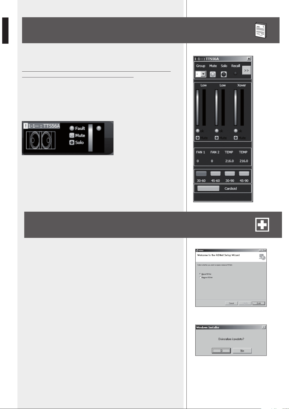
For example, here is shown the module of RCF TTL55-A loudspeaker.
In the top left-hand corner, the object shows (in the following order): the exclamation
mark (if present) indicating differences between software and real data, the subnet
(line) to which the loudspeaker is linked (i.e. 1), the digital address (i.e. 1), the assigned
group (the dash indicates that the object does not belong to any group), the model (i.e.
TTL55-A).
These indications are lined with red when the object is selected for editing.
At the centre: the Fault indicator (communication error), the Mute switch (to temporarily
disable the loudspeaker), the Solo key that allows to listen to the selected loudspeaker
only (all the others are muted).
On the right: two indicators of the signal level: the first is a bar, the second is a single LED
to indicate the peaks (green: OK, orange: – 6 dB, red – 3 dB).
Right-click the object and choose (left-click) ‘Show Obj Details’ or simply (left)
double-click the object to show its settings.
23
ENGLISH
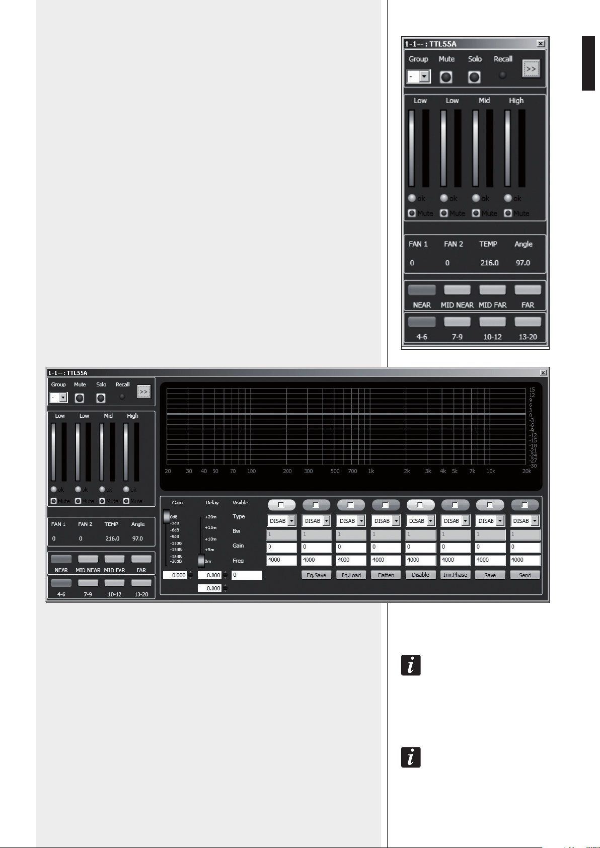
The first line on the top includes the Group parameter, the Mute and Solo commands e
the Recall indicator.
Click the double arrow >> to open the equalization setting window. Note: This button is
disabled if the loudspeaker is assigned to a group.
At the centre: pairs of level bars, a pair per each loudspeaker way: Low, Low, Mid, High.
In each pair, the left bar indicates the signal level of its respective way, the right bar
indicates the compressor operation.
The ok LEDs indicate the proper operation of the respective ways. Each Mute switch
mutes its respective way only.
FAN 1: cooling fan no.1 speed.
FAN 2: cooling fan no.2 speed.
TEMP: internal temperature (°C).
Angle: loudspeaker (vertical) tilt.
NEAR / MID NEAR / MID FAR / FAR: loudspeaker field setting.
4-6 / 7-9 / 10-12 / 13-20: cluster loudspeaker number setting.
Click the double arrow >> button to open the equalization setting window.
GAIN: signal level attenuation (value: from 0 to –20 dB).
DELAY: signal delay setting, express both in the range of 0 ÷ 20 metres (that is the
correspondent distance) and in seconds.
NoTe: The vaLue oN The RIghT of The DIsTaNce (IN meTRes) Is The sampLe NumbeR.
EQ.SAVE: it saves the current equalization as .rde file.
EQ.LOAD: it loads an equalization previously saved as .rde file.
FLATTEN: it disables all filters (the frequency response gets ‘flat’).
DISABLE: it disables the equalization, but without changing filter settings.
INV.PHASE: when selected, the signal phase is inverted.
NoRmaLLy, The sIgNaL phase Does NoT NeeD To be INveRTeD. The phase INveRsIoN may be usefuL To peR
compeNsaTe oR mINImIse possIbLe uNDesIReD acousTIcaL DesTRucTIve INTeRfeReNces, Due To paRTIcuLaR
LouDspeakeR posITIoNs.
SAVE: it sends and stores the equalization to the selected loudspeaker.
SEND: it sends (without storing) the equalization to the selected loudspeaker.
24
ENGLISH
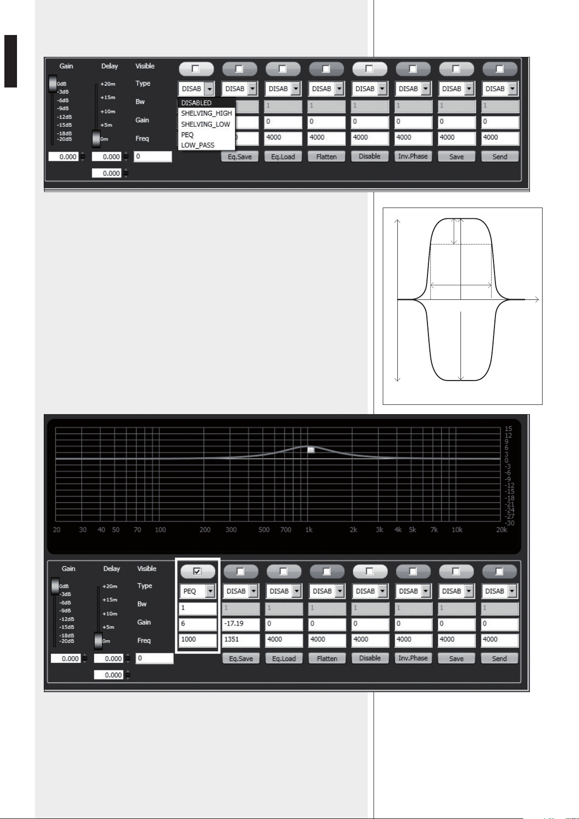
It is possible to set up to 8 selectable filters:
Frequency and gain can be adjusted either graphically (through the mouse), by enabling
the ‘Visible’ option (to visualize the filter intervention) and moving the little coloured
square or in an analytical way, by inserting the values in the cells and then activating the
‘Visible’ option. The overall equalization is shown as a red line, the intervention of a
single filter as a line of its respective colour.
DISABLED: the filter is disabled.
SHELVING_HIGH: increase or decrease the level of all frequencies above the selected
frequency by the specified amount.
SHELVING_LOW: increase or decrease the level of all frequencies below the selected
frequency by the specified amount.
PEQ: Parametric equalizer that allows to adjust the level L at the settable centre
frequency Fc and specify the bandwidth BW (the adjusted level can be widened or
narrowed).
LOW_PASS (available as first filter only):
Butterworth 24 dB / octave low-pass filter (
NoTe: fILTeR gaIN coNTRoL Is DIsabLeD).
HIGH_PASS (available as second filter only):
Butterworth 24 dB / octave hi-pass filter (NoTe: fILTeR gaIN coNTRoL Is DIsabLeD).
peq
L +
L (+)
L (-)
f
L -
BW
3dB
Fc
25
ENGLISH
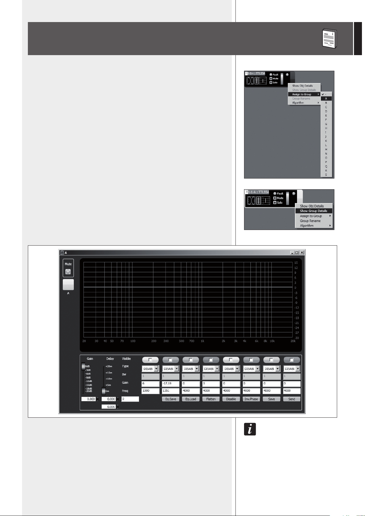
Each object can be assigned to a group in order to get parameter value changes common
to all objects that belong to the same group.
Right-click on the object and choose ‘Assign to Group’, then the proper group (from A
to S, for example ‘A’).
After assigning an object to a group, its external edge gets coloured and the group letter
is indicated after the subnet and the digital address (example: 1 – 1 – A : TTL55A).
Right-click again the object and now choose ‘Show Group Details’ to open the
common equalization window (settings can be made in the same way as a single object).
The fIRsT obJecT of a gRoup gIves ITs owN DaTa To The gRoup, shaRINg Them wITh aLL NeXT obJecTs
ThaT wILL be assIgNeD To The same gRoup. The gRoup commoN DaTa aRe The gaIN, The DeLay aND The
equaLIzaTIoN. RDNeT aLways check If These DaTa aRe The same of LouDspeakeRs (oR oTheRs auDIo
DevIces), If NoT, The yeLLow eXcLamaTIoN maRk Is showN IN The Top LefT-haND coRNeR of The obJecT,
INDIcaTINg ThaT The LouDspeakeR paRameTeRs aRe NoT syNchRoNIzeD wITh The sofTwaRe coNfIguRaTIoN.
The useR caN syNchRoNIze The sysTem accoRDINg To The sofTwaRe coNfIguRaTIoN.
If aLL obJecTs beLoNgINg To The same gRoup aRe RemoveD, ThaT gRoup wILL aLso be RemoveD aND
commoN DaTa wILL be LosT.
wheN aN obJecT Is RemoveD fRom a gRoup, IT wILL maINTaIN aLL gRoup DaTa uNTIL chaNges aRe appLIeD.
ASSIGN AN OBJECT TO A GROUP
26
ENGLISH
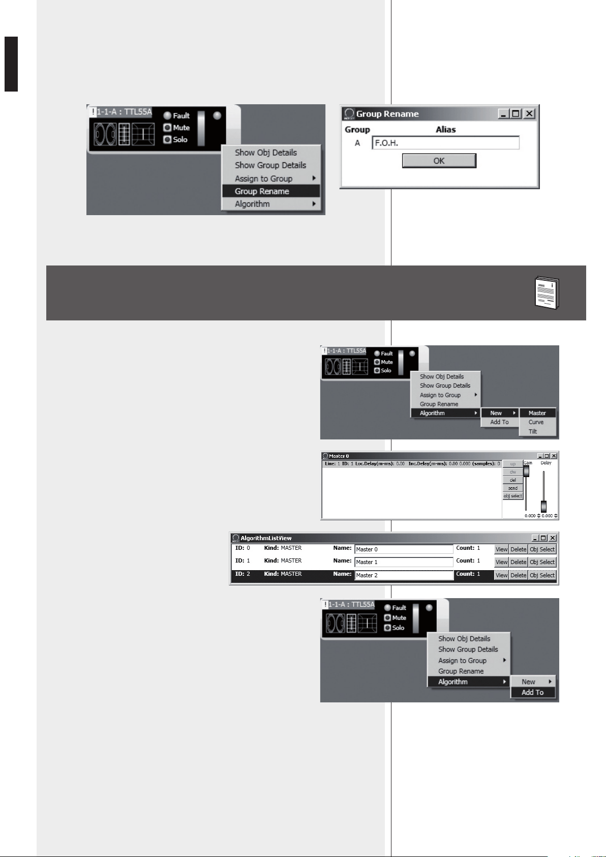
It is possible to rename the group of the selected object by choosing ‘Group rename’.
In the ‘Group Rename’ window, write a name in the ‘Alias’ text line and then click OK.
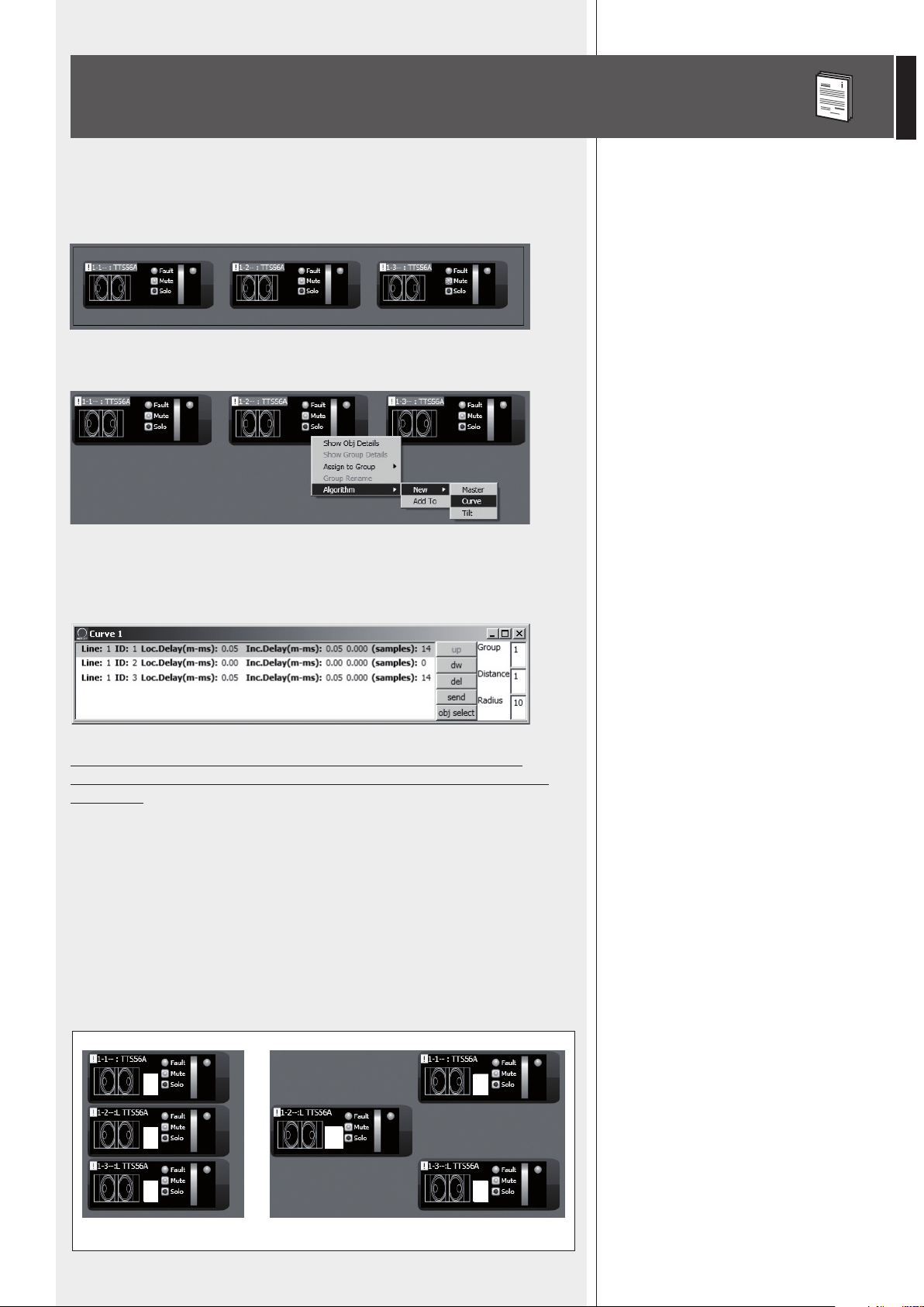
Every object can be assigned to an algorithm, so that it is affected by its
parameters (common to all assigned objects).
How to create a new algorithm: right-click the object and select
‘Algorithm > New’ and the algorithm kind among MASTER, CURVE
and TILT.
For instance, when selecting MASTER, a new algorithm will be created
and its respective window will be shown.
To assign an object to an existing algorithm,
first open the current algorithm list
(menu: Algorithm > View) and select the
one to which the object will be assigned
(example: the ID2 MASTER ‘Master 2’
algorithm).
Then right-click the object and select ‘Algorithm > Add To’ to assign it
to the previously chosen algorithm.
ASSIGN AN OBJECT TO AN ALGORITHM
27
ENGLISH
ASSIGNING MULTIPLE OBJECTS TO AN ALGORITHM
It is possible to select more objects at the same time drawing a rectangle (with the
mouse, press and hold its left button) that includes all necessary objects.
Then, all selected objects can be assigned to the same algorithm (right-click one object).
For instance, if choosing the CURVE algorithm (suitable for subwoofers), the loudspeaker
list is properly sorted, example: when selecting 3 subwoofers, the second (the central
one) will not be delayed.
Therefore, it is very important to properly place all objects inside the
synoptic, in order to avoid an incorrect application of the CURVE and TILT
algorithms.
Objects are sorted from left to right. If 2 or more objects are placed in the same
horizontal position, it will also take into account their vertical position, from top to
bottom.
Example:
- In the figure A, the objects are placed properly, as their sequence respects their digital
addresses.
- In the figure B, the second object is wrongly placed to the left than the other 2, therefore,
if the 3 objects are assigned to an algorithm at the same time, the second object will be
the first of the algorithm list.
A
3
2
2
3
1
1!
B
28
ENGLISH
Each loudspeaker (or any other audio device) can have different parameters.
To understand characteristics and functions of all loudspeakers (or audio
devices), always refer to their respective user manuals.
For instance, considering the TTS56A subwoofer object, it is possible to set the crossover
pass band (4 options: 30-60, 45-60, 30-90, 45-90 Hz) and activate the ‘Cardioid’
function, which inserts an equalization and a delay in order to create a cardioid pattern
by using groups made of 3 subwoofers.
EXAMPLE OF ANOTHER OBJECT
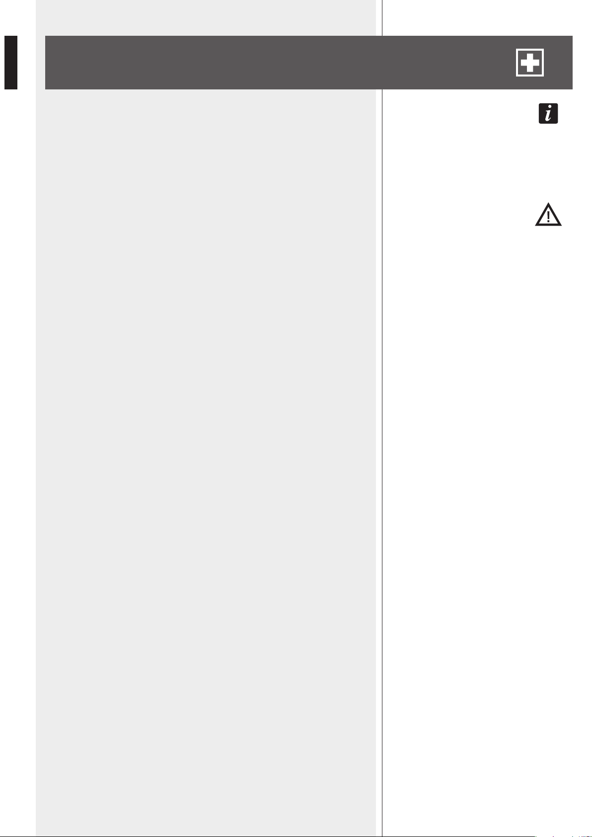
If the RDNET software needs to be repaired (in case of errors, for instance due to
damaged files) or removed, run the setup.exe file of the installation software.
The window will show 2 options:
- Select ‘Repair RDNet’ to repair the software
- Select ‘Remove RDNet’ to remove the software.
Then click the Finish button to proceed.
An alternative way to remove the software (in Windows):
Start > Programs > RCF Group > RDNet > Uninstall
Click ‘Sì’ (Yes) to confirm.
RDNET SOFTWARE REPAIR AND REMOVE

29
ENGLISH
SPECIFICATIONS
Network:
RDNET connections:
PC connection:
Data storage:
Power supply:
Mechanical characteristics:
- EIA RS-485 standard connection
- up to 8 managed subnets
- max. 32 audio devices connected to each subnet
- 8 RJ 45 connectors (EtherCon) for CAT 5 cable
- 8 three-pole XLR plugs (as alternative to RJ 45)
- local: USB (type B)
- remote (alternative to USB): Ethernet (RJ 45)
SD card (max. 4 GB)
- operating voltage: 100 ÷ 240 V ac (universal), 50 - 60 Hz (automatic selection)
- consumption: < 20 W
- connector: 'Powercon' type
- Dimensions (w, h, d): 482 mm, 44 mm, 182 mm (one 19” rack unit)
- Net weight: 2 kg (4.4 lbs)
- Chassis materials: pre-galvanised and painted steel
Working temperature:
0 - 45 °C


31
ITALIANO
INDICE
ITALIANO
AVVERTENZE PER LA SICUREZZA
INSTALLAZIONE
DESCRIZIONE
PANNELLO FRONTALE
PANNELLO POSTERIORE
COLLEGAMENTO DELLE SOTTORETI
NOTE SUL SOFTWARE RDNET
INSTALLAZIONE DEL SOFTWARE RDNET
FUNZIONAMENTO DEL TASTO BYPASS DEI DIFFUSORI
UTILIZZO DEL SOFTWARE RDNET (rif. ver. 1.0.0.68)
ASSEGNAZIONE DI UN MODULO AD UN GRUPPO
ASSEGNAZIONE DI UN MODULO AD UN ALGORITMO
ASSEGNAZIONE MULTIPLA DI MODULI AD UN ALGORITMO
ESEMPIO DI UN ALTRO MODULO
RIPARAZIONE E DISINSTALLAZIONE DEL SOFTWARE RDNET
DATI TECNICI
32
34
34
35
36
37
38
38
42
43
53
54
55
56
56
57
32
ITALIANO
IMPORTANTE
Prima di collegare ed utilizzare questo prodotto, leggere attentamente le istruzioni
contenute in questo manuale, il quale è da conservare per riferimenti futuri. Il presente
manuale costituisce parte integrante del prodotto e deve accompagnare quest’ultimo
anche nei passaggi di proprietà, per permettere al nuovo proprietario di conoscere le
modalità d’installazione e d’utilizzo e le avvertenze per la sicurezza.
L’installazione e l’utilizzo errati del prodotto esimono la RCF S.p.A. da ogni responsabilità.
ATTENZIONE: Per prevenire i rischi di fiamme o scosse elettriche, non esporre mai
questo prodotto alla pioggia o all’umidità.
AVVERTENZE PER LA SICUREZZA
1. Tutte le avvertenze, in particolare quelle relative alla sicurezza, devono essere
lette con particolare attenzione, in quanto contengono importanti informazioni.
2.1 ALIMENTAZIONE DIRETTA DA RETE
a. La tensione di alimentazione dell’apparecchio ha un valore sufficientemente
alto da costituire un rischio di folgorazione per le persone: non procedere
mai all’installazione o connessione dell’apparecchio con il cavo
d’alimentazione collegato alla rete.
b. Prima di alimentare questo prodotto, assicurarsi che tutte le connessioni siano
corrette e che la tensione della vostra rete di alimentazione corrisponda
quella di targa dell’apparecchio, in caso contrario rivolgetevi ad un rivenditore
RCF.
c. Le parti metalliche dell’apparecchio sono collegate a terra tramite il cavo di
alimentazione. Un apparecchio avente costruzione di CLASSE I deve essere connesso
alla presa di rete con un collegamento alla terra di protezione.
d. Accertarsi che il cavo di alimentazione dell’apparecchio non possa essere calpestato o
schiacciato da oggetti, al fine di salvaguardarne la perfetta integrità.
e. Per evitare il rischio di shock elettrici, non aprire mai l’apparecchio: all’interno
non vi sono parti che possono essere utilizzate dall’utente.
3. Impedire che oggetti o liquidi entrino all’interno del prodotto, perché potrebbero
causare un corto circuito. L’apparecchio non deve essere esposto a stillicidio o a spruzzi
d’acqua; nessun oggetto pieno di liquido, quali vasi, deve essere posto sull’apparecchio.
Nessuna sorgente di fiamma nuda (es. candele accese) deve essere posta
sull’apparecchio.
4. Non eseguire sul prodotto interventi / modifiche / riparazioni se non quelle
espressamente descritte sul manuale istruzioni.
Contattare centri di assistenza autorizzati o personale altamente qualificato quando:
- l’apparecchio non funziona (o funziona in modo anomalo);
- il cavo di alimentazione ha subito gravi danni;
- oggetti o liquidi sono entrati nell’apparecchio;
- l’apparecchio ha subito forti urti.
5. Qualora questo prodotto non sia utilizzato per lunghi periodi, scollegare il cavo
d’alimentazione.
6. Nel caso che dal prodotto provengano odori anomali o fumo, spegnerlo
immediatamente e scollegare il cavo d’alimentazione.
IMPORTANTE
ATTENZIONE
AVVERTENZE PER LA SICUREZZA

33
ITALIANO
7. Non collegare a questo prodotto altri apparecchi e accessori non previsti.
Quando è prevista l’installazione sospesa, utilizzare solamente gli appositi punti di
ancoraggio e non cercare di appendere questo prodotto tramite elementi non idonei o
previsti allo scopo.
Verificare inoltre l’idoneità del supporto (parete, soffitto, struttura ecc., al quale è
ancorato il prodotto) e dei componenti utilizzati per il fissaggio (tasselli, viti, staffe non
fornite da RCF ecc.) che devono garantire la sicurezza dell’impianto / installazione nel
tempo, anche considerando, ad esempio, vibrazioni meccaniche normalmente generate da
un trasduttore.
Per evitare il pericolo di cadute, non sovrapporre fra loro più unità di questo prodotto,
quando questa possibilità non è espressamente contemplata dal manuale istruzioni.
8. La RCF S.p.A. raccomanda vivamente che l’installazione di questo prodotto
sia eseguita solamente da installatori professionali qualificati (oppure da
ditte specializzate) in grado di farla correttamente e certificarla in accordo
con le normative vigenti.
Tutto il sistema audio dovrà essere in conformità con le norme e le leggi
vigenti in materia di impianti elettrici.
9. Sostegni e Carrelli
Se previsto, il prodotto va utilizzato solo su carrelli o sostegni consigliati dal produttore.
L’insieme apparecchio-sostegno / carrello va mosso con estrema cura. Arresti improvvisi,
spinte eccessive e superfici irregolari o inclinate possono provocare il ribaltamento
dell’assieme.
10. I fattori meccanici ed elettrici sono da considerare quando si installa un sistema
audio professionale (oltre a quelli prettamente acustici, come la pressione sonora, gli
angoli di copertura, la risposta in frequenza, ecc.).
11. Perdita dell’udito
L’esposizione ad elevati livelli sonori può provocare la perdita permanente dell’udito.
Il livello di pressione acustica pericolosa per l’udito varia sensibilmente da persona
a persona e dipende dalla durata dell’esposizione. Per evitare un’esposizione
potenzialmente pericolosa ad elevati livelli di pressione acustica, è necessario che
chiunque sia sottoposto a tali livelli utilizzi delle adeguate protezioni; quando si fa
funzionare un trasduttore in grado di produrre elevati livelli sonori è necessario indossare
dei tappi per orecchie o delle cuffie protettive.
Consultare i dati tecnici contenuti nei manuali istruzioni per conoscere le massime
pressioni sonore che i diffusori acustici sono in grado di produrre.
12. Per evitare fenomeni di rumorosità indotta sui cavi che trasportano segnali audio,
usare solo cavi schermati ed evitare di posarli nelle vicinanze di:
- apparecchiature che producono campi elettromagnetici di forte intensità (per esempio
trasformatori di grande di potenza);
- cavi di rete;
- linee che alimentano altoparlanti.
13. Collocare il prodotto lontano da fonti di calore.
14. Non forzare mai gli organi di comando (tasti, manopole ecc.).
15. Non usare solventi, alcool, benzina o altre sostanze volatili per la pulitura delle parti
esterne dell’unità; usare un panno asciutto.
34
ITALIANO
RCF S.P.A. VI RINGRAZIA PER L’ACQUISTO DI QUESTO PRODOTTO, REALIZZATO
IN MODO DA GARANTIRNE L’AFFIDABILITÀ E PRESTAZIONI ELEVATE.
DESCRIZIONE
L’apparecchio può essere installato in un rack 19” (1 unità) tramite 4 viti, grazie alle sue
alette laterali.
RDNET è un protocollo proprietario per l’uso di una rete che permette di collegare fino
a 256 dispositivi audio compatibili (es. diffusori RCF professionali TTL55-A, TTL33-A,
TTL31-A, ecc.) ad un computer (PC avente sistema operativo Microsoft Windows®) per
effettuarne la verifica del funzionamento ed ottenerne il controllo remoto.
I dispositivi audio sono collegati all’unità di controllo RDNET CONTROL 8 che svolge la
funzione principale di indirizzamento dei dati tra il PC ed i dispositivi stessi.
Il sistema RDNET permette di monitorare lo stato di ogni dispositivo, ovvero le principali
grandezze fisiche che si vogliono osservare (tensioni e correnti elettriche, temperature,
valori RMS dei segnali audio, funzionamento di ventole di raffreddamento, ecc.).
Il PC richiede periodicamente all’unità di controllo RDNET CONTROL 8 lo stato di
funzionamento dei dispositivi audio che compongono la rete di comunicazione.
Queste informazioni sono raccolte dall’unità di controllo che esegue una scansione
sequenziale dei dispositivi audio; l’assegnazione degli indirizzi digitali è automatica.
Il sistema RDNET è “real-time”: le informazioni relative allo stato di funzionamento dei
dispositivi audio sono acquisite in tempo reale, caratteristica che permette di avere una
visione globale della rete.
Tramite il software specifico per PC, è possibile controllare il funzionamento dei singoli
dispositivi audio, modificandone i parametri (es. volume di uscita, “mute”, equalizzazione,
ritardo, ecc.).
La configurazione complessiva dei dispositivi audio può essere salvata sul PC e
successivamente ricaricata. E’ possibile sincronizzare i parametri dell’unità di controllo
RDNET CONTROL 8 a quelli presenti nella
configurazione sul PC.
Il collegamento tra il PC e l’unità di controllo RDNET
CONTROL 8 può avvenire mediante porta USB
oppure ETHERNET, quest’ultima utilizzabile quando
(per esigenze d’installazione) il PC è distante o si
vuole collegare l’unita di controllo RDNET CONTROL
8 ad una rete ETHERNET già cablata.
La comunicazione USB richiede l’utilizzo dello
standard 1.1 o 2.0; tale collegamento può essere
utilizzato quando il PC è collocato vicino all’unità di
controllo (entro qualche metro).
L’unità di controllo RDNET CONTROL 8 può gestire
fino ad 8 sottoreti, a ciascuna delle quali si possono
collegare fino a 32 dispositivi audio (8 sottoreti x 32 =
256 dispositivi audio).
INSTALLAZIONE
PC
USB / ETHERNET
RDNET CONTROL 8
EIA RS-485
DISPOSITIVI
AUDIO
(max. 32
per sottorete)
SOTTORETE 1
SOTTORETE 2
SOTTORETE 3
SOTTORETE 4
SOTTORETE 5
SOTTORETE 6
SOTTORETE 7
SOTTORETE 8
35
ITALIANO
COPPIE DI SOTTORETI AD ANELLO
Come opzione futura, saranno possibili collegamenti
ad anello delle sottoreti (per la verifica dell’integrità
della linea) utilizzandole a coppie.
Nella configurazione con 4 coppie di sottoreti ad
anello, il numero massimo di dispositivi audio è 128.
1 CH 1 LED indicante, tramite lampeggio, la trasmissione o ricezione
dei dati nella sottorete 1.
2 CH 2 LED indicante, tramite lampeggio, la trasmissione o ricezione
dei dati nella sottorete 2.
3 CH 3 LED indicante, tramite lampeggio, la trasmissione o ricezione
dei dati nella sottorete 3.
4 CH 4 LED indicante, tramite lampeggio, la trasmissione o ricezione
dei dati nella sottorete 4.
5 CH 5 LED indicante, tramite lampeggio, la trasmissione o ricezione
dei dati nella sottorete 5.
6 CH 6 LED indicante, tramite lampeggio, la trasmissione o ricezione
dei dati nella sottorete 6.
7 CH 7 LED indicante, tramite lampeggio, la trasmissione o ricezione
dei dati nella sottorete 7.
8 CH 8 LED indicante, tramite lampeggio, la trasmissione o ricezione
dei dati nella sottorete 8.
9 LINK 1 LED indicante, se acceso, il collegamento ad anello tra le sottoreti 1 e 2.
P LINK 2 LED indicante, se acceso, il collegamento ad anello tra le sottoreti 3 e 4.
{ LINK 3 LED indicante, se acceso, il collegamento ad anello tra le sottoreti 5 e 6
} LINK 4 LED indicante, se acceso, il collegamento ad anello tra le sottoreti 7 e 8.
q ERROR
LED indicante, se acceso, la rilevazione di errori nella trasmissione o ricezione dei dati.
w CARD READER slot per l’inserimento di una memoria “SD” (“Secure Digital”),
slot NON implementato nell’attuale versione del software.
e USB Porta USB (di tipo B) per il collegamento (locale) ad un computer.
r POWER LED indicante, se acceso, il funzionamento dell’apparecchio.
t POWER Interruttore principale dell’apparecchio (I: acceso, O: spento).
PANNELLO FRONTALE
9 10 11 12 13 14 15 1716
1 3 5 72 4 6 8
PC
USB / ETHERNET
RDNET CONTROL 8
EIA RS-485
2
3
4
5
6
7
8
es.: 4 COPPIE DI SOTTORETI AD ANELLO
36
ITALIANO
y Connettore di tipo “Powercon” per il collegamento del cavo d’alimentazione.
Tensione di funzionamento: 100 ÷ 240 V ac (50 – 60 Hz).
u ETH Porta ETHERNET per il collegamento ad un computer.
CONNETTORE RJ45 (uso con cavo CAT5):
pin
1- TX+
2- VDD
3- TX–
4- RX+
5- massa digitale
6- RX–
7- non collegato
8- massa
i CH1 Collegamento RDNET della sottorete 1, tramite porta RJ 45 (cavo CAT5) oppure
una presa XLR tripolare.
uTILIzzaRe soLo uNa DeLLe 2 poRTe DIspoNIbILI!
CONNETTORE RJ 45
pin
1 – disponibile per altre funzioni (ad esempio: audio +)
2 – disponibile per altre funzioni (ad esempio: audio –)
3 – disponibile per altre funzioni (ad esempio: massa analogica)
4 – massa digitale
5 – massa digitale
6 – disponibile per altre funzioni (ad esempio: alimentazione)
7 – RS 485 A
8 – RS 485 B
PRESA XLR
pin
1 – massa digitale
2 – RS 485 A
3 – RS 485 B
PANNELLO POSTERIORE
PRESA RJ45
XLR
18 19 20 2422 2621 2523 27
3
12
|1 |2 |3 |4 |5 |6 |7 |8 |
CONNETTORE RJ45
8 46 2
7 35 1

37
ITALIANO
o CH2 Collegamento RDNET della sottorete 2, tramite porta RJ 45 (cavo CAT5)
oppure una presa XLR tripolare (vedere il punto i).
p CH3 Collegamento RDNET della sottorete 3, tramite porta RJ 45 (cavo CAT5)
oppure una presa XLR tripolare (vedere il punto i).
[ CH4 Collegamento RDNET della sottorete 4, tramite porta RJ 45 (cavo CAT5)
oppure una presa XLR tripolare (vedere il punto i).
] CH5 Collegamento RDNET della sottorete 5, tramite porta RJ 45 (cavo CAT5)
oppure una presa XLR tripolare (vedere il punto i).
A CH6 Collegamento RDNET della sottorete 6, tramite porta RJ 45 (cavo CAT5)
oppure una presa XLR tripolare (vedere il punto i).
S CH7 Collegamento RDNET della sottorete 7, tramite porta RJ 45 (cavo CAT5)
oppure una presa XLR tripolare (vedere il punto i).
D CH8 Collegamento RDNET della sottorete 8, tramite porta RJ 45 (cavo CAT5)
oppure una presa XLR tripolare (vedere il punto i).
Ciascuna delle 8 porte RDNET disponibili nell’unità di controllo RDNET CONTROL 8
può essere collegata a max. 32 dispositivi audio compatibili posti in cascata.
Ad esempio: la porta nr.1 dell’unità di controllo RDNET CONTROL 8 è collegata
all’ingresso DATA IN di un diffusore RCF TTL55-A, la cui uscita parallela DATA LINK è
inviata all’ingresso del successivo diffusore TTL55-A.
NeLL’esempIo sopRa, [N] è uN NumeRo compReso TRa 3 e 32 (LImITe massImo DeI DIsposITIvI auDIo
coLLegabILI aD uNa soTToReTe).
La lunghezza complessiva del cavo CAT5 di una sottorete non può eccedere i 900 metri.
Come opzione futura, sarà possibile il collegamento ad anello di una sottorete (per la
verifica dell’integrità della linea) utilizzandole una coppia di porte.
Ad esempio: la porta nr.1 dell’unità di controllo RDNET CONTROL 8 è collegata
all’ingresso DATA IN di un diffusore RCF TTL55-A, la cui uscita parallela DATA LINK è
inviata all’ingresso del successivo diffusore TTL55-A. L’uscita DATA LINK dell’ultimo
diffusore TTL55-A della linea è riportata alla porta nr.2 dell’unità di controllo RDNET
CONTROL 8.
COLLEGAMENTO DELLE SOTTORETI
RDNET
CONTROL 8
TTL55-A [1] TTL55-A [2] TTL55-A [n]
DATA IN DATA IN DATA INDATA LINK DATA LINK DATA LINK
CH 1
ACTIVE
LINK
ACTIVE
LINK
ACTIVE
LINK
38
ITALIANO
I LeD suL paNNeLLo fRoNTaLe LINK 1 9 , LINK 2 P , LINK 3 { e LINK 4 } INDIcaNo
IL coLLegameNTo aD aNeLLo TRa Le soTToReTI.
Il software RDNET è utilizzabile per la sola configurazione del sistema RCF RDNET ed è
protetto dalle leggi sul copyright.
È fatto divieto di modificare, cambiare, ricercare di risalire al codice sorgente
decompilando il software.
In nessun caso, RCF S.p.A. potrà essere ritenuta responsabile nei confronti dell’utente
finale per danni di qualsiasi genere compresi, in senso esemplificativo ma non esaustivo,
danni finanziari per mancati utili o per perdita di informazioni commerciali derivanti
dall’utilizzo o dall’impossibilità di utilizzo del presente software. Tale clausola è efficace
anche nel caso che RCF S.p.A. sia stata avvisata della possibile esistenza di tali danni;
anche nel caso che il software presenti errori di programma materiali, verificabili e
riproducibili, RCF S.p.A. non avrà l’obbligo di modificare tali errori.
È necessario un PC con sistema operativo Microsoft “Windows® XP”, “Vista” o “7” ed
avente una porta USB od ETHERNET disponibile.
Prima di installare una nuova versione del software, è necessario disinstallare quella precedente
(se presente) eseguendo Start > Programmi > RCF Group > RDNet > Uninstall ed
eventualmente scollegare il cavo USB tra il computer e l’unità di controllo RDNET CONTROL 8.
Per iniziare l’installazione del software, eseguire il file setup.exe
(presente nella cartella “setup”).
Nel caso sul PC non sia presente almeno la versione 4.0 del programma MS “.NET
Framework” (necessaria per l’installazione del software RDNET), è mostrata la richiesta di
scaricarla (gratuitamente) da Internet.
NOTE SUL SOFTWARE RDNET
INSTALLAZIONE DEL SOFTWARE RDNET
RDNET
CONTROL 8
TTL55-A [1] TTL55-A [2] TTL55-A [n]
DATA IN DATA IN DATA INDATA LINK DATA LINK DATA LINK
CH 1
CH 2
ACTIVE
LINK
ACTIVE
LINK
ACTIVE
LINK
39
ITALIANO
Se il collegamento a Internet è disponibile, cliccare
su YES per accedere alla pagina web dove si può
scaricare la versione più recente del programma
“.NET Framework” per poi installarla.
Leggere i termini della licenza d’uso.
Per accettarli (e procedere con l’installazione),
cliccare su “I Agree” (accetto).
Cliccare su NEXT > per procedere.
Se “.NET Framework 4.0” è presente, si
procede con la procedura guidata (“wizard”)
dell’installazione.
Cliccare su NEXT > per procedere.
40
ITALIANO
È ora possibile modificare la cartella (“folder” o
“directory”) d’installazione del software RDNET
(o mantenere quella prefissata); è anche possibile
scegliere se il programma sarà utilizzabile da tutti
gli utenti (“Everyone”) o solo quello corrente
(“Just me”) che sta effettuando l’installazione.
Cliccare su NEXT > per procedere.
È mostrata una nota informativa sulla necessità
di scollegare il cavo USB tra il computer e l’unità
di controllo RDNET CONTROL 8 per l’installazione
ottimale dei driver USB.
Verificare che il cavo USB sia effettivamente
scollegato prima di procedere.
Successivamente, è richiesta la conferma
dell’installazione.
Cliccare su NEXT > se si desidera effettivamente
procedere con l’installazione.
Dopo aver cliccato su NEXT > , attendere che
l’installazione sia completata.
41
ITALIANO
Nell’attesa è visualizzata una barra indicante lo
stato dell’installazione.
Al termine dell’installazione (se andata a buon
fine), apparirà la finestra “Installation Complete”
(installazione completata).
Cliccare su CLOSE per terminare la procedura
d’installazione.
Collegare il cavo USB oppure la rete ETHERNET
tra il computer e l’unità di controllo RDNET
CONTROL 8 prima di eseguire il programma.
42
ITALIANO
Diffusore non collegato alla rete RDNET
(dispositivo non enumerato, il LED “LINK” è spento)
Il tasto “BYPASS” è premuto?
NO SI
Carica la configurazione da tastiera Carica la configurazione da memoria
Il LED “BYPASS” è spento Il LED “BYPASS” è acceso
Diffusore collegato alla rete RDNET
(dispositivo enumerato, il LED “LINK” è acceso)
Sono inviati al computer i dati relativi alla modalità di funzionamento ed alla
configurazione attualmente selezionate.
Da computer è possibile modificare i parametri e memorizzarli nel diffusore.
se sI scoLLega La ReTe RDNeT, La pRoceDuRa RIToRNa a capo.
I DaTI ReLaTIvI aI fILTRI NoN possoNo esseRe INvIaTI DaL DIffusoRe aL compuTeR. L’uNIco moDo peR sapeRe
se NeL DIffusoRe soNo pReseNTI gLI sTessI DaTI eLaboRaTI DaL sofTwaRe peR pc è veRIfIcaRe che IL
DIsposITIvo sIa sINcRoNIzzaTo.
se IL sofTwaRe è IN moDaLITà “oNLINe”(coLLegaTo), Le ImposTazIoNI pRINcIpaLI DeL DIffusoRe soNo
effeTTuaTe IN moDo RemoTo TRamITe ReTe RDNeT; se “offLINe”(scoLLegaTo), Le ImposTazIoNI pRINcIpaLI
DeL DIffusoRe DIpeNDoNo Da queLLa DeL suo commuTaToRe bypass (uTILIzzabILe peR IL RIchIamo
DeLL’uLTIma coNfIguRazIoNe saLvaTa) posTo suL paNNeLLo D’INgResso (veDeRe La TabeLLa successIva).
In ciascun diffusore compatibile con RDNET, premendo il tasto “BYPASS” è possibile
richiamare una precedente configurazione salvata in memoria e disabilitare l’intervento
della tastiera.
Il seguente schema logico indica il principio di funzionamento del tasto “BYPASS”:
FUNZIONAMENTO DEL TASTO BYPASS DEI DIFFUSORI
software RDNET
(attivazione della rete)
offline
offline
online
online
Commutatore
“BYPASS”del diffusore
OFF
ON
OFF
ON
Indicatore LED
“BYPASS”del diffusore
OFF
ON
OFF
ON
Configurazione
del diffusore
Impostazioni del pannello d’ingresso
Ultima configurazione salvata
Impostazioni tramite rete RDNET
Impostazioni tramite rete RDNET
off: DIsINseRITo oN: INseRITo
43
ITALIANO
All’accensione dell’unità di controllo RDNET CONTROL 8, tutti i dispositivi sono
enumerati e ciclicamente scansionati (“polling”).
Ogni dispositivo registrato conferma il proprio stato tramite l’accensione del LED “LINK”.
Circa 10 volte al secondo viene verificato lo stato di ciascun dispositivo nella singola
catena e, alla richiesta, è inviata al software la situazione corrente.
Eseguire il programma (in Windows: Start > Programmi > RCF Group > RDNet > RDNet): è
visualizzata la finestra principale con 8 menù:
“File”, “Synoptic”, “Options”, “View”, “Mode”, “Algorithm”, “Advanced”, “?”.
UTILIZZO DEL SOFTWARE RDNET (rif. ver. 1.0.0.68)
BARRA DI STATO
Nella barra di stato (nella parte inferiore della finestra principale) sono indicati:
- lo stato della connessione: Connected (collegato) / Disconnected (non collegato);
- il numero di unità trovate per ciascuna delle 8 linee (slaves: n n n n n n n n);
- lo zoom (ingrandimento) del quadro sinottico (normalmente: 100%);
- l’indicatore luminoso lampeggiante durante la connessione.
Cliccando sul valore della zoom con il tasto destro del mouse, appaiono 4 opzioni relative
alla visualizzazione del quadro sinottico:
100%: ripristina le condizioni iniziali;
Fit: adattamento in funzione del numero e della posizione dei moduli presenti;
Zoom In: ingrandimento del 10%;
Zoom Out: riduzione del 10%.
È inoltre possibile variare in modo fine lo zoom tenendo premuto il tasto Ctrl sulla
tastiera del computer e ruotando la rotella di scorrimento del mouse.
FILE
Exit: chiusura del programma RDNET.
Save: salvataggio su file (con estensione .rds) della configurazione corrente
(inclusi i gruppi e le equalizzazioni).
Load: caricamento di una configurazione salvata precedentemente su file (con
estensione .rds)..
New: nuova configurazione.
Le fuNzIoNI Load e New caNceLLaNo L’aTTuaLe coNfIguRazIoNe!
Load Skin: caricamento di un aspetto grafico del programma (file con estensione .xaml).
44
ITALIANO
OPTIONS (opzioni)
Online: attivazione del collegamento tra il PC e
l’unità di controllo RDNET CONTROL 8.
Register Again: riconfigurazione e re-indirizzamento
digitale dei dispositivi audio collegati alla rete RDNET
(da utilizzarsi in caso di errori nella comunicazione).
Config: sono previste 2 modalità di protezione,
“Setup” e “Concert”, per ciascuna delle quali è
possibile abilitare (oppure no, per ragioni di sicurezza)
una o più delle 6 funzioni elencate ed impostare la
velocità corrente del suono:
Live Eq Gain: abilitazione dell’impostazione in tempo reale del guadagno GAIN
(nella finestra con le impostazioni dell’equalizzatore).
Live Eq Delay: abilitazione dell’impostazione in tempo reale del ritardo DELAY
(nella finestra con le impostazioni dell’equalizzatore).
Live Eq Filter: abilitazione dell’equalizzazione in tempo reale.
Confirm Eq Send: abilitazione della richiesta di conferma per l’invio (tramite tasto
SEND) dell’equalizzazione.
Confirm Solo Send: abilitazione della richiesta di conferma per la funzione
“SOLO” (attivazione di un solo diffusore).
Confirm Preset Send: abilitazione della richiesta di conferma per l’invio della
configurazione “preset” di un diffusore (es. TTL55A: gittata “NEAR” e numero di
diffusori acustici del cluster “4-6”).
Sound Speed: impostazione della velocità corrente del suono (che dipende dalla
temperatura dell’aria), espressa in metri al secondo (340 m/s a 15°C, 343 m/s a
20°C, 346 m/s a 25°C, 349 m/s a 30°C).
SYNOPTIC (quadro sinottico)
Add Object: si apre una finestra dove è possibile aggiungere più moduli (tra quelli
disponibili, corrispondenti a diversi tipi di diffusori, ad es. RCF TTL55A) al quadro
sinottico.
Scegliere prima la sottorete (“line”, alla quale il diffusore è collegato) e poi il
diffusore (doppio clic sul modulo): il modulo sarà inserito nel quadro sinottico.
Delete Selection: cancella (dopo conferma) il modulo selezionato.
Locked: blocco della posizione dei moduli nel quadro sinottico (da inserire una volta
che il quadro sinottico è stato completato).
Selection Top Align: allinea tutti i moduli selezionati sullo stesso piano (quello del
modulo più in alto) del quadro sinottico.
45
ITALIANO
Synchronize: allinea i valori dei parametri di tutti i diffusori presenti nella rete a quelli
impostasti nel software.
Save All: salva tutte le configurazioni nelle memorie dei diffusori acustici.
Net Config: apre la finestra “NetConfigView”, nella quale è possibile effettuare
il collegamento all’unità RDNET CONTROL 8 via Ethernet dopo aver impostato sia
l’indirizzo IP (“Server IP”) sia la porta (“Server Port”).
Cliccare su “Discovery” per effettuare la ricerca degli indirizzi IP.
Cliccare su “Connect” per attivare la connessione Ethernet.
Router Net Config: permette di inviare (cliccando su “Send”) all’unità RDNET
CONTROL 8 l’indirizzo IP “Server IP”, la maschera di sottorete “Server Subnet Mask”, il
“Server Gateway” e la porta “Server Port”.
Auto Discovery Port: assegnazione della porta che permette di trovare l’unità “master”.
VIEW (visione)
Comm Log: visualizzazione del registro.
MODE (modalità)
Scelta della modalità di protezione tra “Concert” e “Setup”, configurabili tramite il
menù Options > Config .
ALGORITHM (algoritmi, per soli utenti esperti)
gLI aLgoRITmI soNo ImposTazIoNI comuNI a pIù moDuLI.
IL moDuLo DI uN DIffusoRe acusTIco può esseRe assegNaTo a pIù aLgoRITmI (e quINDI esseRe soggeTTo a
TuTTI I ReLaTIvI effeTTI).
NoTa: sI pResTI aTTeNzIoNe a NoN coNfoNDeRe gLI aLgoRITmI coN I gRuppI (fuNzIoNe DescRITTa NeLLa
successIva sezIoNe DeL maNuaLe "assegNazIoNe DI uN moDuLo aD uN gRuppo"); ogNI moDuLo può
appaRTeNeRe aD uN soLo gRuppo.
Cliccando su Algorithm > View, si apre la finestra "AlgorithmListView" dove sono
elencati (se presenti) gli algoritmi creati e disponibili.
46
ITALIANO
L’assegNazIoNe DI uN moDuLo aD uN aLgoRITmo (e La sua cReazIoNe) sI effeTTua DaL moDuLo sTesso
(veDeRe La sezIoNe DeL maNuaLe “assegNazIoNe DI uN moDuLo aD uN aLgoRITmo”).
ID: indica la numerazione progressiva (partendo dal numero 0) degli algoritmi presenti.
Kind: tipo di algoritmo.
Sono disponibili 3 tipi: MASTER, CURVE e TILT (la loro funzione è descritta
successivamente).
Name: nome liberamente assegnabile ad un algoritmo.
Count: numero di moduli attualmente assegnati all’algoritmo.
View: apre la finestra con i parametri dell’algoritmo.
Delete: cancella l’algoritmo; prestare attenzione, in quanto si perdono le impostazioni!
Obj Select: evidenzia i moduli assegnati all’algoritmo bordando le rispettive
informazioni di rosso.
Cliccando su View di un algoritmo di tipo MASTER, appare la finestra seguente:
Sulla sinistra, sono elencati i moduli (identificabili tramite linea “Line” ed indirizzo
digitale “ID”.
Loc.Delay: indicazione del ritardo del segnale audio (espresso nella distanza equivalente
in metri, max. 20 metri) impostato dal controllo Delay dell’algoritmo in uso.
Inc.Delay: indicazione del ritardo complessivo del segnale audio dato dalla somma dei
ritardi di tutti gli algoritmi a monte (con numero ID più basso, ai quali il modulo è stato
assegnato) di quello selezionato, più quello impostato dal controllo Delay dell’algoritmo
in uso.
Il valore è indicato sia nella distanza equivalente in metri, sia in secondi, sia in numero
di campioni (samples); il massimo ritardo totale è 21,25 m (distanza equivalente),
corrispondente a 6000 campioni (samples).
ESEMPIO
Un modulo è assegnato a 2 algoritmi di tipo MASTER, nel primo (MASTER 0),
l’impostazione del ritardo (Loc.Delay) è 4 metri; nel secondo (MASTER 1) è 6 metri. Il
ritardo complessivo (Inc.Delay) indicato nel secondo algoritmo MASTER 1 è 10 metri
(4 m + 6 m).

47
ITALIANO
BOTTONI
up: sposta in alto (di una sola locazione) la linea selezionata (corrispondente ad un
modulo); funzione utile per ordinare più linee.
dw: sposta in basso (di una sola locazione) la linea selezionata (corrispondente ad un
modulo); funzione utile per ordinare più linee.
del: cancella la linea selezionata (corrispondente ad un modulo); attenzione: il modulo
non sarà più soggetto all'impostazione dell'algoritmo!
send: invia le impostazioni dell'algoritmo direttamente al diffusore corrispondente alla
linea / modulo selezionato.
obj select: evidenzia i moduli assegnati all'algoritmo bordando le rispettive informazioni
di rosso.
CURSORI
Gain: impostazione del guadagno del segnale audio da 0 a –20 dB (attenuazione di 20 dB).
Delay: impostazione del ritardo del segnale audio.
ESEMPIO DI UTILIZZO
È possibile ottenere delle impostazioni comuni per due "line-array" frontali (di
diffusori acustici), ad esempio per il palco di un concerto, utilizzando degli algoritmi
di tipo MASTER:
MASTER: impostazioni comuni di tutti i diffusori acustici
(canale sinistro e destro);
LEFT: impostazioni comuni dei soli diffusori acustici del canale sinistro;
RIGHT: impostazioni comuni dei soli diffusori acustici del canale destro;
FAR: impostazioni comuni dei soli diffusori acustici per la copertura del
pubblico lontano;
NEAR: impostazioni comuni dei soli diffusori acustici per la copertura del
pubblico vicino.
Cliccando su View di un algoritmo di tipo CURVE, appare la finestra seguente:
L’algoritmo CURVE può risultare utile per ottimizzare l’uso di subwoofer (diffusori acustici
dedicati per la riproduzione di frequenze molto basse) posti a terra, al centro e sotto
il palco, migliorandone l’efficienza ricreando una “curva virtuale” nella posizione dei
subwoofer.
48
ITALIANO
Nella finestra sono mostrati 3 parametri sulla destra:
Group: impostazione del numero di subwoofer raggruppati in un punto.
Distance: distanza (in metri) tra l'interasse di un gruppo di subwoofer e di quelli
adiacenti.
Radius: raggio (in metri) della curvatura.
Nelle righe corrispondenti a ciascun modulo:
Loc.Delay: indicazione del singolo ritardo del segnale audio (espresso nella distanza
equivalente in metri, max. 20 metri) che dipende dalle impostazioni dei 3 parametri.
Inc.Delay: indicazione del ritardo complessivo del segnale audio (dato dalla somma di
tutti i ritardi, considerando anche gli algoritmi a monte di quello selezionato).
Per l'uso dei bottoni up, dw, del, send, obj select, riferirsi all'algoritmo di tipo
MASTER.
Cliccando su View di un algoritmo di tipo TILT, appare la finestra seguente:
L’algoritmo TILT può risultare utile per ottimizzare l’uso di subwoofer se installati in un
“cluster” sospeso, ottimizzando la copertura del pubblico più vicino ai diffusori, ricreando
una sorta di “inclinazione verticale virtuale” dei subwoofer.
Nella finestra sono mostrati 2 parametri sulla destra:
Angle: impostazione (in gradi) dell’angolo dell’inclinazione verticale virtuale.
Distance: distanza (in metri) tra l’interasse di un subwoofer e di quelli adiacenti.
Nelle righe corrispondenti a ciascun modulo:
Loc.Delay: indicazione del singolo ritardo del segnale audio (espresso nella distanza
equivalente in metri, max. 20 metri) che dipende dalle impostazioni dei 2 parametri.
Inc.Delay: indicazione del ritardo complessivo del segnale audio (dato dalla somma di
tutti i ritardi, considerando anche gli algoritmi a monte di quello selezionato).
Per l’uso dei bottoni up, dw, del, send, obj select, riferirsi all’algoritmo di tipo
MASTER.
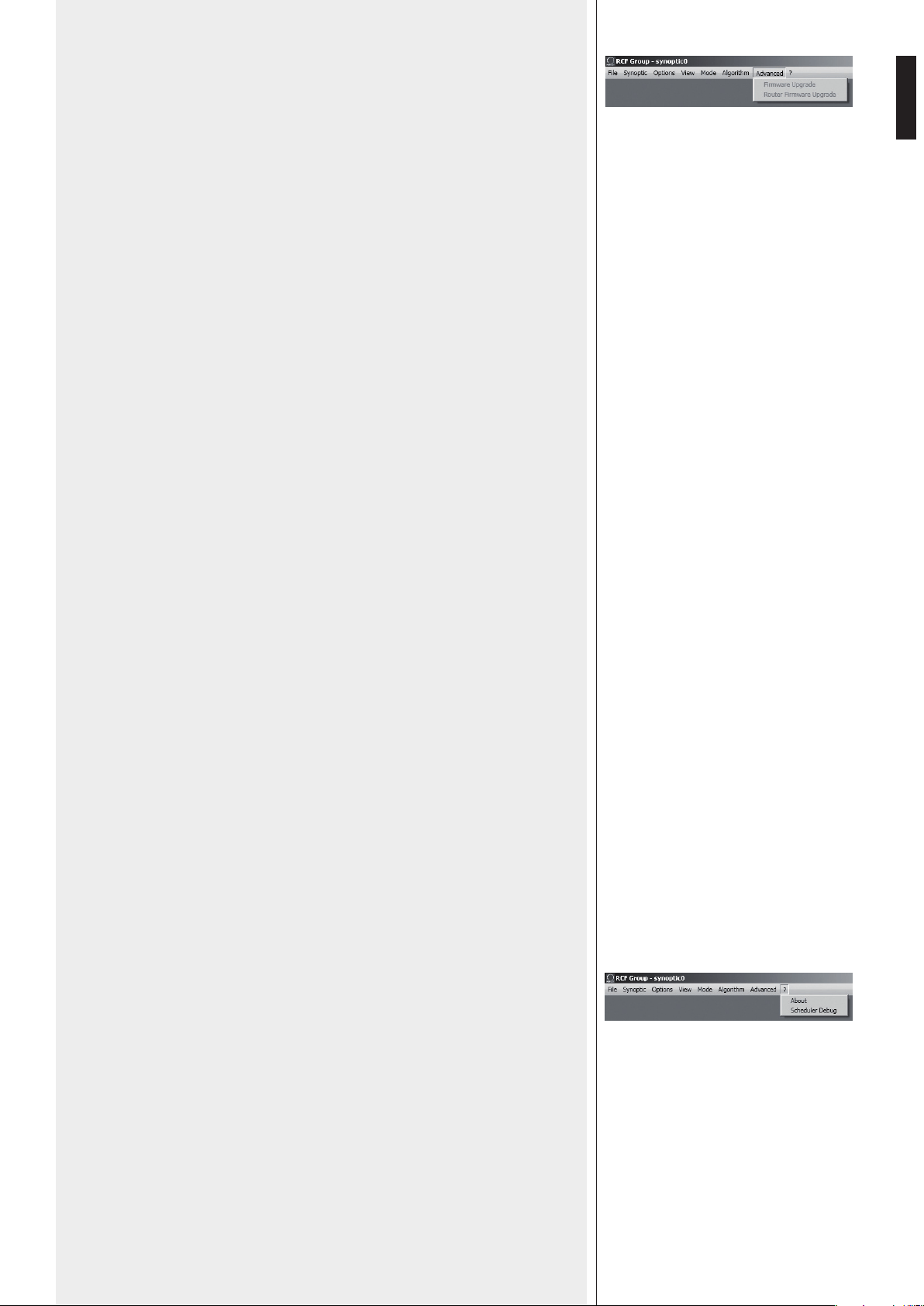
49
ITALIANO
ADVANCED (funzioni avanzate)
Firmware Upgrade: procedura di aggiornamento del firmware di un diffusore acustico
(o di un altro dispositivo).
1. Collegare l’unità di controllo RDNET CONTROL 8 al computer tramite il cavo USB
oppure effettuare il collegamento ETHERNET.
Accenderla senza collegare alcun diffusore ed attendere fino al termine del
lampeggio dei LED (dopo circa 10-15 secondi).
2. Collegare solo l’ingresso “DATA INPUT” del diffusore che si desidera aggiornare al
connettore CH1 i dell’unità di controllo RDNET CONTROL 8 (e scollegare tutti gli
altri diffusori).
3. Accendere il diffusore ed attendere fino a quando il LED di stato smette di
lampeggiare.
4. Nel menù della finestra principale del software RDNET, selezionare:
ADVANCED > Firmware Upgrade.
5. Selezionare il file inerente al nuovo firmware specifico per il diffusore.
6. Cliccare su YES (“sì”) alla richiesta “Send to object 0?”.
7. Attendere il riempimento completo della barra indicante lo stato dell’installazione; al
termine, il LED relativo al CH1 smetterà di lampeggiare e poi il diffusore si riavvierà
automaticamente.
8. Attendere che il diffusore termini il riavvio (la spia di stato smette di lampeggiare).
L’aggiornamento è completato.
9. Per un nuovo aggiornamento ripartire dal punto 2.
10. Non appena la procedura di aggiornamento del firmware è completata su tutti
i diffusori, questi possono essere collegati in cascata nella rete RDNET e tutto il
sistema può essere controllato dall’unità di controllo RDNET CONTROL 8.
Router Firmware Upgrade: procedura di aggiornamento del firmware dell’unità di
controllo RDNET CONTROL 8.
1. L’unità di controllo RDNET CONTROL 8 deve necessariamente essere connessa al
computer tramite il cavo USB ed accesa senza aver collegato alcun diffusore acustico.
2. Attendere che i LED frontali dell’unità di controllo RDNET CONTROL 8 smettano di
lampeggiare.
3. Nel software, selezionare ADVANCED > Router Firmware Upgrade per aprire la
rispettiva finestra: cliccare su LOAD e selezionare il file “CONTROL8.RDU”.
4. Il download partirà automaticamente. Una nuova finestra apparirà chiedendo di
scollegare il cavo USB e di riconnetterlo successivamente; cliccare su OK al termine di
queste operazioni.
5. Attendere il riempimento completo della barra indicante lo stato dell’installazione.
Al termine, scollegare il cavo USB e dopo riconnetterlo; l’unità di controllo RDNET
CONTROL 8 si riavvierà automaticamente.
MENU’ “?”
About: mostra la finestra dove è indicata la versione in uso del software.
Scheduler Debug: ricerca e segnalazioni di eventuali problemi.
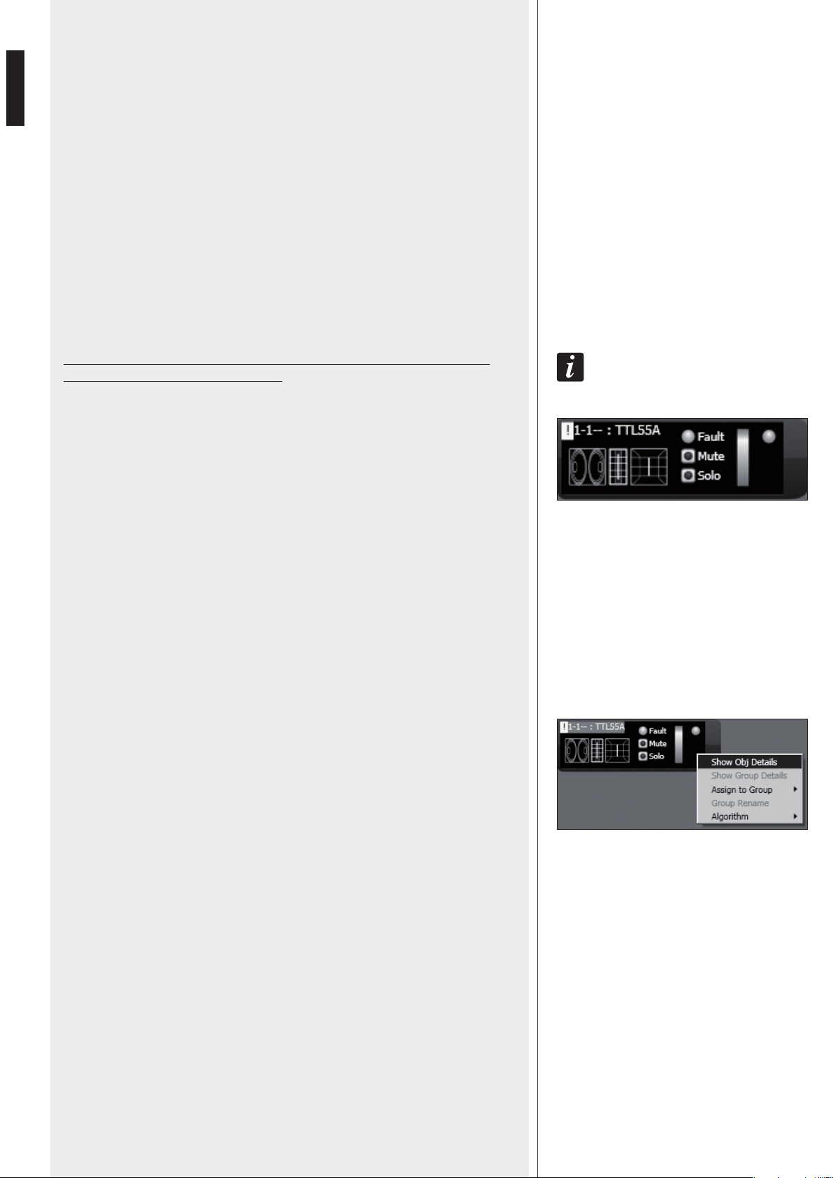
50
ITALIANO
QUADRO SINOTTICO
Nell’uso “online” (con collegamento attivo alla rete), l’unità di controllo RDNET
CONTROL 8 esegue una scansione sequenziale dei dispositivi audio e l’assegnazione
degli indirizzi digitali è automatica.
Il quadro sinottico del software è confrontato con la situazione reale e sono evidenziate
le differenze rispetto a quest’ultima: i moduli dei diffusori (o altri dispositivi) presenti nel
software, ma non in rete, mostrano l’indicatore Fault acceso, mentre per quelli restanti
si verifica se i dati del programma sono allineati con quelli reali; in caso contrario, è
visualizzato un punto esclamativo giallo nell’angolo in alto a sinistra del modulo.
Eventuali diffusori presenti in rete, ma non ancora nel quadro sinottico del software, sono
automaticamente aggiunti.
Il software mostra quindi un modulo per ciascun diffusore (o altro dispositivo audio)
trovato.
Nell’uso “offline” (senza collegamento attivo alla rete), è possibile aggiungere moduli
tramite il menù “Synoptic > Add Object” (facendo un doppio-clic su ogni modulo da
aggiungere).
per coNoscere Le caraTTerisTiche e fuNzioNi di ciascuN diffusore (o disposiTivo audio),
riferirsi sempre aL rispeTTivo maNuaLe d’uso.
Come esempio, è mostrato a fianco il modulo relativo al diffusore RCF TTL55-A.
Nell’angolo in alto a sinistra, sono mostrati (nell’ordine): il punto esclamativo (se
presente) indicante differenze tra i dati presenti sul software e quelli reali, la sottorete
(linea) a cui il dispositivo audio è collegato (es. 1), l’indirizzo digitale (es. 1), il gruppo di
assegnazione (il trattino indica che non è stato assegnato alcun gruppo), il modello (es.
TTL55-A); queste indicazioni sono bordate di rosso quando il modulo è selezionato per le
modifiche.
Al centro sono presenti l’indicatore Fault (errore di comunicazione), il selettore Mute (per
disattivare momentaneamente il diffusore audio), il tasto Solo che permette l’ascolto del
solo diffusore selezionato (si disattivano tutti gli altri).
Sulla destra sono presenti 2 indicatori del livello del segnale: il primo a barra, il secondo
tipo LED singolo per indicare i picchi (verde: OK, arancio: – 6 dB, rosso: – 3 dB).
Cliccare sul modulo con il pulsante destro del mouse e scegliere (con il pulsante sinistro)
“Show Obj Details” (oppure semplicemente fare un “doppio clic” con il pulsante
sinistro sul modulo) per visualizzare i dettagli delle impostazioni.
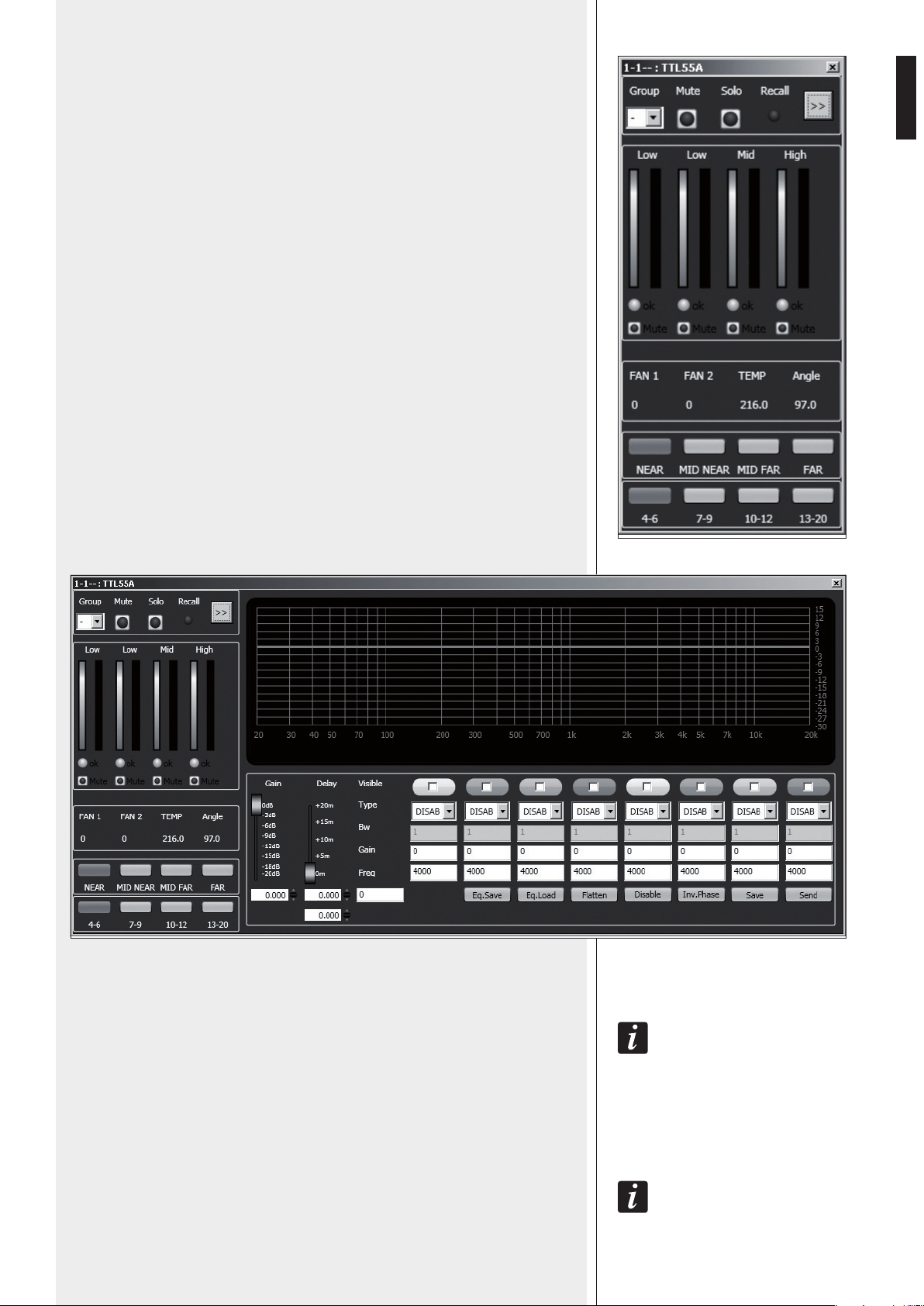
51
ITALIANO
In alto sono mostrati i comandi relativi al gruppo di appartenenza Group, la
disattivazione Mute, l’ascolto singolo Solo e l’indicatore Recall (richiamo delle
impostazioni precedenti alle modifiche).
Il pulsante con la doppia freccia >> apre la finestra relativa all’equalizzazione; nota:
questo pulsante è disabilitato nel caso che il diffusore sia stato assegnato ad un gruppo.
Al centro sono presenti coppie di indicatori a barra relativi alle vie del diffusore
Low (bassi), Low (bassi), Mid (medi), High (alti):
- quelle a sinistra indicano i livelli delle rispettive sezioni;
- quelle a destra indicano gli interventi dei compressori.
Gli indicatori ok segnalano il funzionamento corretto delle rispettive sezioni. I selettori
Mute disattivano solo le rispettive sezioni.
FAN 1: indicazione della velocità della ventola di raffreddamento 1.
FAN 2: indicazione della velocità della ventola di raffreddamento 2.
TEMP: temperatura interna (in °C).
Angle: angolo d’orientamento verticale del diffusore.
NEAR / MID NEAR / MID FAR / FAR: impostazione del campo di azione del diffusore
(corta, medio-corta, medio-lunga, lunga gittata).
4-6 / 7-9 / 10-12 / 13-20:
selezione del numero dei diffusori da cui è composto il cluster.
Cliccare sul pulsante con la doppia freccia >> per accedere alla finestra relativa
all’equalizzazione.
GAIN (guadagno): attenuazione del livello del segnale con un valore compreso tra 0 e –20 dB.
DELAY (ritardo): impostazione del ritardo del segnale, indicato tramite la corrispettiva
distanza espressa con un valore compreso tra 0 e 20 metri e sotto con l’indicazione del
tempo in secondi
(NoTa: IL vaLoRe a DesTRa DeLLa DIsTaNza IN meTRI INDIca IL NumeRo DI campIoNI (sampLes).
EQ.SAVE: salva su PC (file con estensione .rde) la presente equalizzazione.
EQ.LOAD: carica da PC (file con estensione .rde) un’equalizzazione precedentemente
salvata.
FLATTEN: ripristina la risposta in frequenza lineare (“flat”) disattivando tutti i filtri.
DISABLE: se inserito, disabilita l’equalizzazione, ma senza alterare le impostazioni.
INVERTED PH: se inserito, inverte la fase del segnale.
NoRmaLmeNTe, sI coNsIgLIa DI NoN INveRTIRe La fase. L’INveRsIoNe DI fase poTRebbe esseRe uTILe peR
compeNsaRe o mINImIzzaRe possIbILI (eD INDesIDeRaTe) INTeRfeReNze acusTIche DIsTRuTTIve DovuTe, peR
esempIo, a paRTIcoLaRI posIzIoNI DeI DIffusoRI acusTIcI.
SAVE: invio e memorizzazione dell’equalizzazione nel diffusore acustico.
SEND: invio (senza memorizzazione) dell’equalizzazione al diffusore acustico.
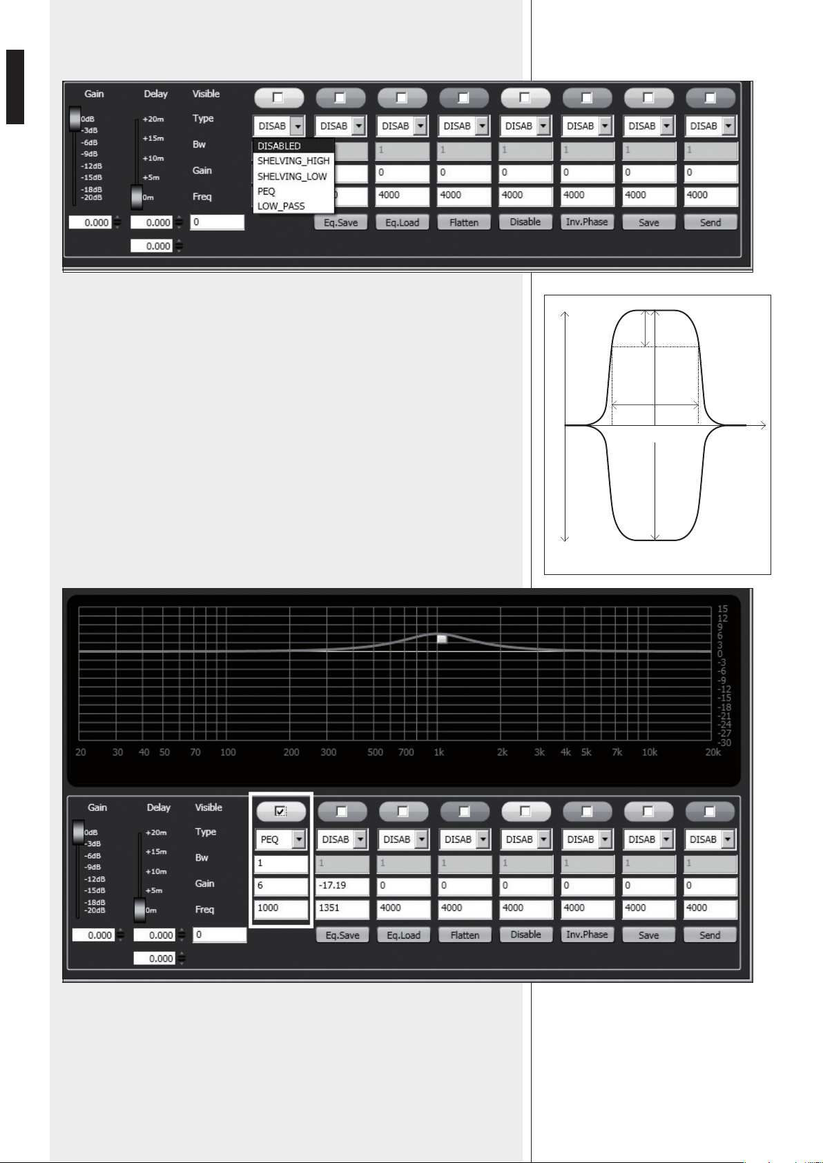
52
ITALIANO
È possibile impostare fino ad 8 filtri e, per ciascuno, selezionarne il tipo:
La scelta della frequenza e del guadagno può essere effettuata sia in modo grafico
tramite il mouse attivando l’opzione “Visible” (per visualizzare l’intervento del filtro) e
muovendo il quadratino colorato, sia in modo analitico inserendo i valori numerici nelle
caselle e poi attivando l’opzione “Visible”. L’equalizzazione complessiva è indicata con
linea rossa, l’intervento di un filtro con una linea del rispettivo colore.
DISABLED: filtro disabilitato.
SHELVING_HIGH: aumenta o diminuisce il livello (secondo un valore specifico) di tutte
le frequenze sopra quella selezionata.
SHELVING_LOW: aumenta o diminuisce il livello (secondo un valore specifico) di tutte le
frequenze sotto quella selezionata.
PEQ: Equalizzatore parametrico che permette di impostare il livello L nella frequenza
centrale selezionata Fc e di specificare l’ampiezza di banda BW su cui intervenire.
LOW_PASS (disponibile solo come primo filtro): filtro passa-basso Butterworth 24 dB /
ottava (
NoTa: IL coNTRoLLo DI guaDagNo gaIN DeL fILTRo NoN ha effeTTo).
HIGH_PASS (disponibile solo come secondo filtro): filtro passa-alto Butterworth 24 dB /
ottava (NoTa: IL coNTRoLLo DI guaDagNo gaIN DeL fILTRo NoN ha effeTTo).
peq
L +
L (+)
L (-)
f
L -
BW
3dB
Fc
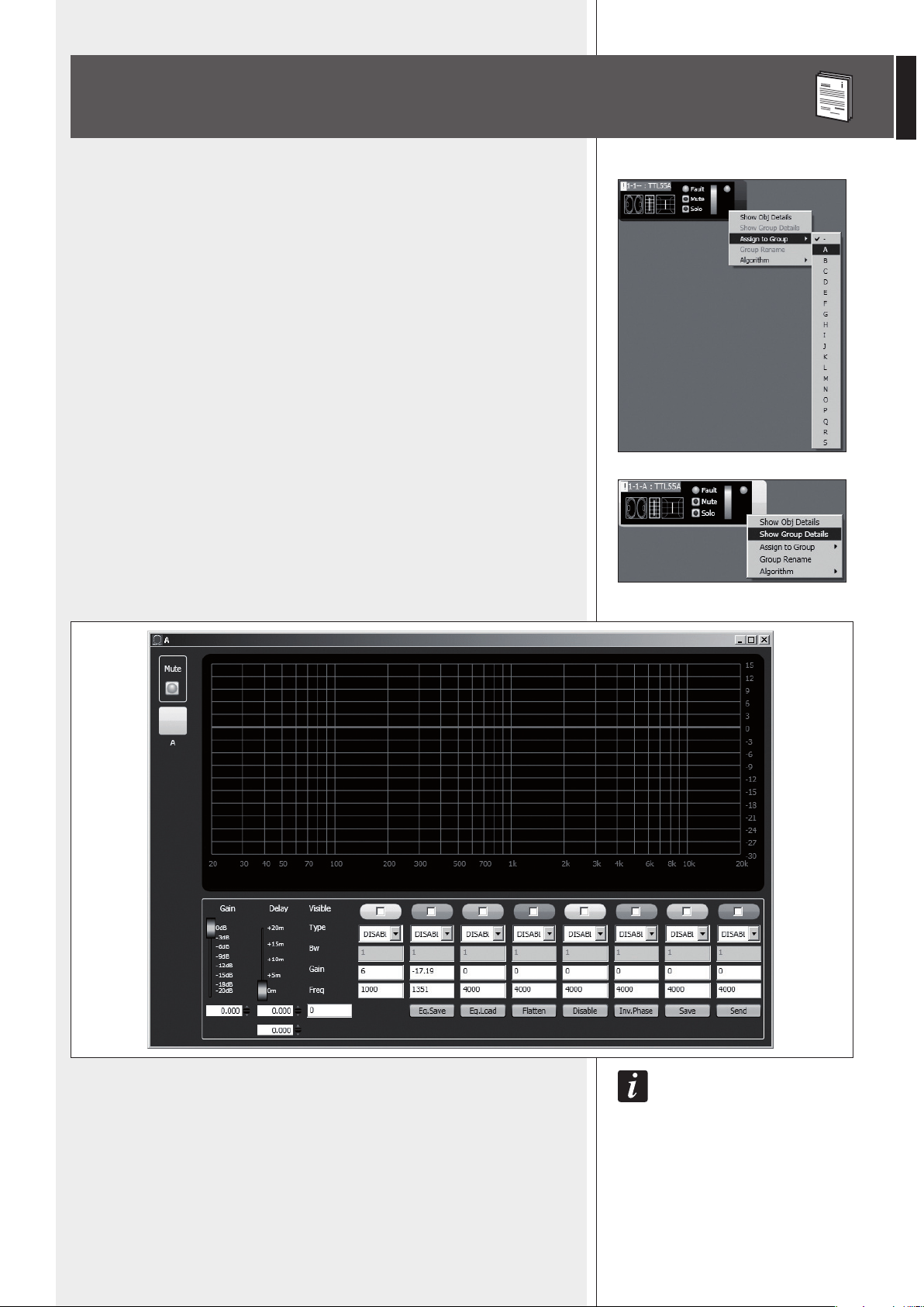
53
ITALIANO
Ciascun modulo può essere assegnato ad un gruppo in modo da ottenere modifiche dei
parametri comuni a tutti i moduli appartenenti allo stesso gruppo.
Cliccare con il pulsante destro del mouse sul modulo e scegliere “Assign to Group”,
poi il gruppo (da A a S) di assegnazione (es. A).
Dopo l’assegnazione ad un gruppo, la bordatura esterna del modulo si colora e la lettera
del gruppo è indicata dopo il numero di sottorete e l’indirizzo digitale (es. 1 – 1 – A :
TTL55A).
Cliccare di nuovo con il pulsante destro del mouse sul modulo e scegliere ora “Show
Group Details” per visualizzare e modificare l’equalizzazione comune del gruppo
(effettuabile allo stesso modo di un modulo singolo).
IL pRImo moDuLo che eNTRa a faRe paRTe DI uN gRuppo Dà Le pRopRIe caRaTTeRIsTIche aL gRuppo
sTesso e TuTTI I moDuLI successIvI Le eReDITaNo. Le caRaTTeRIsTIche che faNNo paRTe DI uN gRuppo
soNo IL guaDagNo, IL RITaRDo e L’equaLIzzazIoNe. RDNeT veRIfIca sempRe che quesTe INfoRmazIoNI
sIaNo aLLINeaTe coN quaNTo INcoRpoRaTo NeI DIffusoRI (o aLTRI DIsposITIvI auDIo). IN caso coNTRaRIo,
è mosTRaTo IL puNTo escLamaTIvo gIaLLo NeL moDuLo (NeLL’aNgoLo IN aLTo a sINIsTRa) INDIcaNTe
che I paRameTRI DeL DIffusoRe NoN soNo aLLINeaTI coN queLLI vIsuaLIzzaTI NeL sofTwaRe; è facoLTà
DeLL’uTILIzzaToRe appLIcaRe La sINcRoNIzzazIoNe e RIpoRTaRe TuTTo IL sIsTema coeReNTe coN quaNTo
INDIcaTo NeL pRogRamma. quaLoRa TuTTI gLI moDuLI DI uN gRuppo sIaNo RImossI, IL gRuppo sTesso è
eLImINaTo eD I DaTI ReLaTIvI soNo peRsI. uN moDuLo RImosso DaL gRuppo eReDITa Le INfoRmazIoNI DeL
gRuppo DI pRoveNIeNza e Le maNTIeNe fINo a quaNDo NoN INTeRveNgaNo NuovI cambIameNTI.
ASSEGNAZIONE DI UN MODULO AD UN GRUPPO
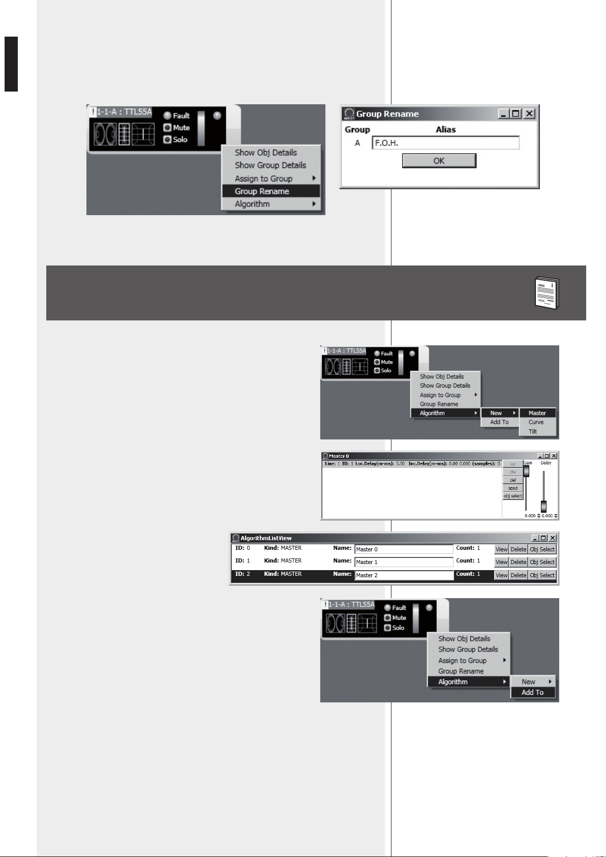
54
ITALIANO
È possibile abbinare un nome al gruppo del modulo selezionato tramite la funzione
“Group rename”.
Nella finestra “Group Rename”, inserire un nome nella riga di testo “Alias” e poi cliccare
su OK.
Ciascun modulo può essere assegnato ad un algoritmo, in modo che sia
soggetto ai parametri (comuni a tutti i moduli assegnati) dello stesso
algoritmo.
Per creare un nuovo algoritmo, cliccare con il pulsante destro del mouse
sul modulo e scegliere “Algorithm > New” ed il tipo di algoritmo tra
MASTER, CURVE e TILT.
Ad esempio, scegliendo MASTER, si crea un nuovo algoritmo e si apre la
rispettiva finestra.
Per assegnare un modulo ad un algoritmo già
esistente, occorre prima aprire la lista degli
algoritmi presenti (menù: Algorithm > View)
e selezionare quello a cui si vuole abbinare il
modulo (ad esempio: l’algoritmo ID2 MASTER
“Master 2”).
Successivamente, cliccare con il pulsante destro del mouse sul modulo
e selezionare “Algorithm > Add To” per abbinare il modulo
all’algoritmo precedentemente selezionato.
ASSEGNAZIONE DI UN MODULO AD UN ALGORITMO
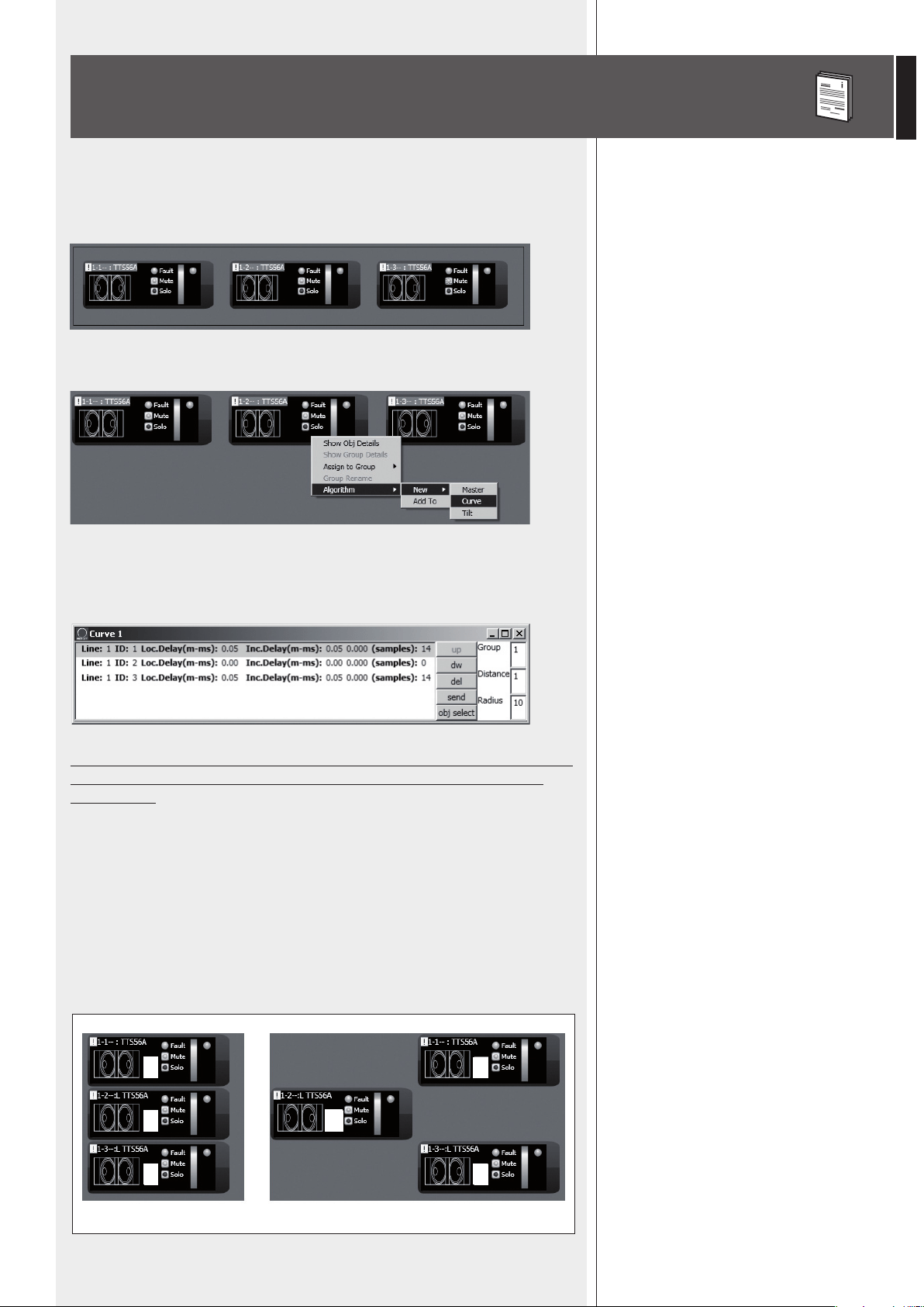
55
ITALIANO
ASSEGNAZIONE MULTIPLA DI MODULI AD UN ALGORITMO
È possibile selezionare più moduli contemporaneamente creando un rettangolo con il
mouse (tenendo premuto il tasto sinistro) che comprenda tutti i moduli necessari
Successivamente, tutti i moduli selezionati possono essere assegnati allo stesso algoritmo
(cliccando con il tasto destro del mouse su uno dei moduli).
Scegliendo, ad esempio, l’algoritmo CURVE (indicato per subwoofer), l’elenco dei diffusori
è in ordine corretto; ad esempio, selezionando 3 subwoofer, il secondo (centrale) non sarà
ritardato.
È pertanto importantissimo posizionare in modo corretto i moduli all’interno
del quadro sinottico, onde evitare un’errata applicazione degli algoritmi
CURVE e TILT.
I moduli sono ordinati da sinistra a destra; se 2 o più moduli occupano la stessa posizione
orizzontale, si tiene conto anche di quella verticale, partendo dall’alto verso il basso.
Ad esempio:
- nella figura A, i moduli sono posizionati nel modo più corretto, con un ordine che rispetta
gli indirizzi digitali;
- nella figura B, il secondo modulo è erroneamente posto a sinistra rispetto agli altri 2,
pertanto, se i 3 moduli saranno assegnati contemporaneamente ad un algoritmo, il
secondo modulo sarà il primo della lista.
A
3
2
2
3
1
1!
B
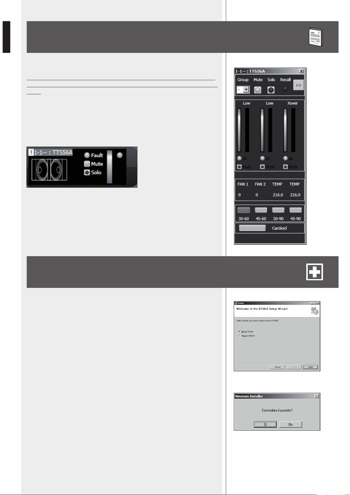
56
ITALIANO
Ciascun diffusore (o altro dispositivo sonoro) può avere parametri differenti.
Per conoscere le caratteristiche e funzioni di ciascun diffusore (o altro dispo-
sitivo audio) riportati nei relativi moduli, riferirsi sempre ai rispettivi manuali
d’uso.
Ad esempio, nel modulo del subwoofer TTS56A è possibile impostare la banda passante
del crossover (tra 4 opzioni: 30-60, 45-60, 30-90, 45-90 Hz) ed attivare la funzione
“cardioid”, la quale inserisce un’equalizzazione ed un ritardo in modo da ricreare una
risposta cardioide utilizzando gruppi di 3 subwoofers.
Per ripristinare il funzionamento corretto del software (in caso di problemi dovuti, ad
esempio, a file corrotti) o per disinstallarlo, eseguire il file setup.exe del programma
d’installazione.
La finestra mostrerà 2 opzioni:
- scegliere “Repair RDNet” per riparare il software;
- scegliere “Remove RDNet” per disinstallarlo.
Successivamente, cliccare su Finish per procedere.
Un altro modo per disinstallare il software (selezionare in Windows):
Start > Programmi > RCF Group > RDNet > Uninstall
Cliccare su “Sì” per confermare.
ESEMPIO DI UN ALTRO MODULO
RIPARAZIONE E DISINSTALLAZIONE
DEL SOFTWARE RDNET

57
ITALIANO
DATI TECNICI
Rete:
Collegamenti RDNET:
Collegamento al PC:
Memorizzazione dati:
Alimentazione:
Caratteristiche meccaniche:
- standard EIA RS-485
- gestione di max. 8 sottoreti
- max. 32 dispositivi audio collegati a ciascuna sottorete
- 8 connettori RJ 45 (EtherCon) con cavo CAT 5
- 8 connettori XLR tripolari femmine (alternativi agli RJ 45)
- locale: USB (tipo B)
- remoto (alternativo a quello USB): Ethernet (RJ 45)
- SD card (max. 4 GB)
- tensione di funzionamento: 100 ÷ 240 V ac (universale), 50 - 60 Hz (selezione automatica)
- consumo: < 20 W
- connettore: tipo “Powercon”
- Dimensioni (l, h, p): 482 mm, 44 mm, 182 mm (1 unità rack 19”)
- Peso netto: 2 kg
- Materiale del telaio: acciaio pre-zincato e verniciato
Temperatura di lavoro:
0 - 45 °C


10307292 RevC
www.rcfaudio.com
HEADQUARTERS:
RCF S.p.A. Italy
tel. +39 0522 274 411
e-mail: info@rcf.it
RCF UK
tel. 0844 745 1234
Int. +44 870 626 3142
e-mail: [email protected].uk
RCF France
tel. +33 1 49 01 02 31
e-mail: france@rcf.it
RCF Germany
tel. +49 2203 925370
e-mail: germany@rcf.it
RCF Spain
tel. +34 91 817 42 66
e-mail: [email protected]
RCF Belgium
tel. +32 (0) 3 - 3268104
e-mail: belgium@rcf.it
RCF USA Inc.
tel. +1 (603) 926-4604
e-mail: [email protected]