Loading ...
MODELS 765H80L • 765H80LB
Page 2
RED
WHITE
BLACK
120 VAC LINE IN
LIGHT
VENT
HEAT
GROUND
RED
BLACK
GROUND
RED
BLUE
WHITE
BLACK
INSTALLATION
WARNING: To reduce the risk of fire, do not store
or use gasoline or other flammable vapors and
liquids in the vicinity of the heater.
CAUTION: High temperature, risk of fire, keep
electrical cords, drapery, furnishings, and
other combustibles at least 3 feet (0.9 m) from
the front of the heater and away from the side
and rear.
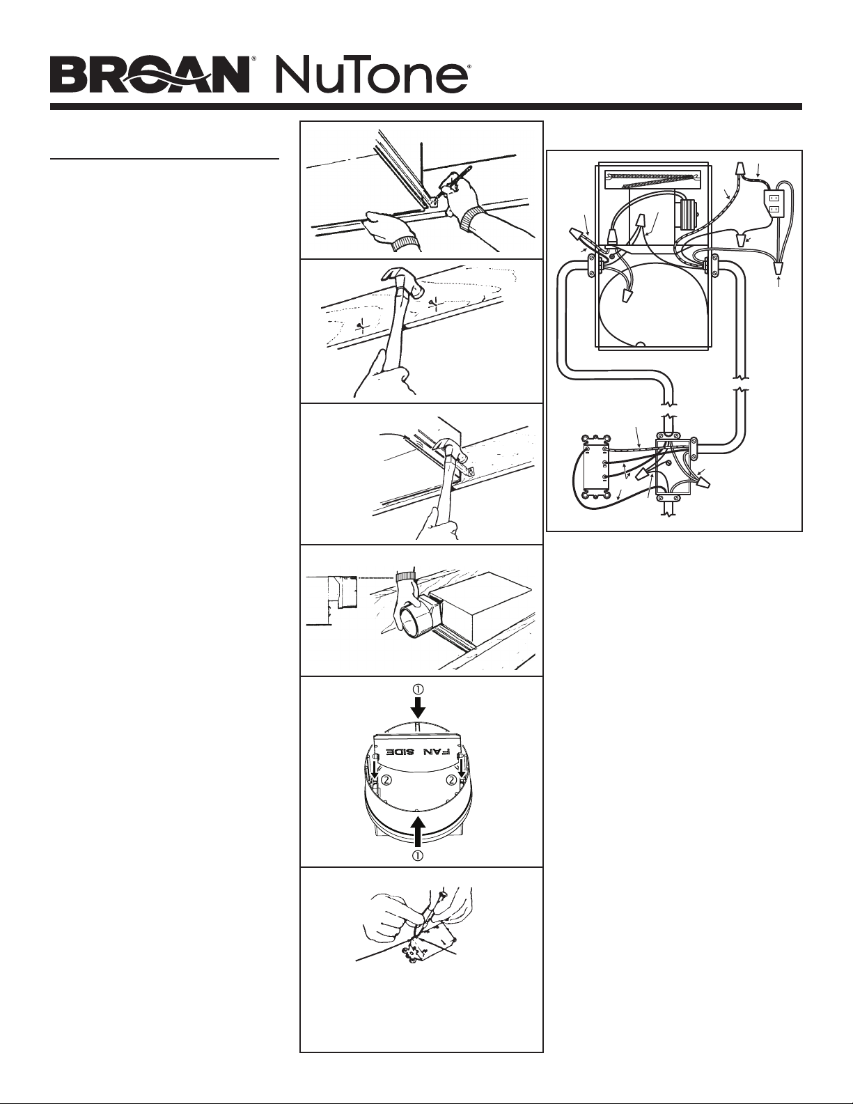
8. For best results, choose a location which allows
fan to be vented outside with the shortest
possible duct run and the fewest number of
elbows.
9. Position unit between joists and extend
mounting brackets. Position brackets such
that the bottom edge of housing will be flush
with finished ceiling. Mark the top of keyhole
slot on all four mounting brackets. (FIG. 6)
10. Remove unit temporarily, and drive nails
partially into joists at all four marked locations.
(FIG. 7)
11. Hang unit from nails and use embossed
measuring guides to check if unit will be flush
with finished ceiling. Drive nails tight. For
wide joist centers: A #8 x 3/8 self-tapping
screw can be used to join extended brackets
together and create a rigid mount. To ensure a
noise-free mount, crimp the bracket channels
tightly around mounting brackets. (FIG. 8)
12. Snap the damper/duct connector onto housing.
Make sure that tabs on the connector lock in
housing slots. (Top of damper/duct connector
will be flush with top of housing.) (FIG. 9)
NOTE: Make sure damper flap is in place inside
of duct connector. If it is not: Squeeze top
and bottom of connector to snap flap back
into place. (FIG. 10)
Installation work and electrical wiring must be
done by a qualied person(s) in accordance
with all applicable codes and standards,
including re-rated construction codes and
standards.
13. Wire unit according to Figure 11.
14. Replace heater assembly removed in STEP 3
and plug it into RED receptacle. Direct wires
away from blower inlet.
15. Replace fan assembly removed in STEP 5 and
plug it into BLACK receptacle.
FIG. 6
FIG. 7
FIG. 8
EMBOSSED
MEASURING
GUIDES
FIG. 9
FLUSH
FIG. 10
FIG. 11
NOTE
WIRE
OPENING
RELEASE SLOT
If the switch has not been wired properly and wires need to
be moved:
1. Each wire opening has a release slot.
2. Push a small nail or screwdriver into release slot while gently
removing wire.
3. DO NOT pull any wire out of the switch without using the
release slot. The switch may be damaged.
Loading ...
Loading ...
Loading ...