
V1.00.000
09-08-2021

i
DN606 Automotive Diagnostic Tool User's Manual
GENERAL SAFETY INSTRUCTIONS
IMPORTANT SAFETY CONSIDERATIONS
WARNING: Before operating this device, be sure to read all content within this
manual, ensuring that you understand the operating procedures, maintenance
requirements and all safety warnings. All users shall have an understanding of
the product, its operating characteristics, and safety operating instructions before
operating this device. Safety information shall be emphasized and understood.
Failure to heed these markings may result in serious personal injury/property
damage.
SAFETY PRECAUTIONS AND WARNINGS
To prevent personal injury or damage to vehicles and/or the test equipment,
please read this user’s manual rst carefully and observe the following safety
precautions at a minimum whenever working on a vehicle:
• Always perform automotive testing in a safe environment.
• Do not attempt to operate or observe the tool while driving a vehicle.
Operating or observing the tool will cause driver distraction and could cause a
fatal accident.
• Wear safety eye protection that meets ANSI standards.
• Keep clothing, hair, hands, tools, test equipment, etc. away from all moving or
hot engine parts.
• Operate the vehicle in a well-ventilated work area: Exhaust gases are
poisonous.
• Put blocks in front of the drive wheels and never leave the vehicle unattended
while running tests.
• Use extreme caution when working around the ignition coil, distributor cap,
ignition wires and spark plugs. These components create hazardous voltages
when the engine is running.
• Put the transmission in P (for A/T) or N (for M/T) and make sure the parking
brake is engaged.
• Keep a re extinguisher suitable for gasoline/chemical/ electrical res nearby.
• Don’t connect or disconnect any test equipment while the ignition is on or the
engine is running.
• Keep the test equipment dry, clean, free from oil/water or grease. Use a mild
detergent on a clean cloth to clean the outside of the test equipment, when
necessary.

ii
DN606 Automotive Diagnostic Tool User's Manual
ASSEMBLY AND ADJUSTMENTS
Prior to each use, a visual inspection shall be made to the device by checking
for abnormal conditions including cracks, leaks, and damaged, loose, or missing
parts.
Storage
Store in a dry location on a level surface.
Disclaimer
• To take full advantage of the unit, you should be familiar with the engine.
• All information, illustrations, and specications contained in this manual are
based on the latest information available at the time of publication. The right is
reserved to make change at any time without notice
FCC Statement
This device complies with part 15 of the FCC Rules. Operation is subject to the
following two conditions: (1) This device may not cause harmful interference,
and (2) this device must accept any interference received, including interference
that may cause undesired operation.

iii
DN606 Automotive Diagnostic Tool User's Manual
Table of Contents
1. Introduction ....................................................................................................1
2. General Information ......................................................................................3
2.1 On-Board Diagnostics (OBD) I ......................................................................3
2.2 On-Board Diagnostics (OBD) II .....................................................................3
2.3 Diagnostic Trouble Codes (DTCs) ................................................................. 5
2.4 Location of the Data Link Connector (DLC)...................................................6
2.4 OBD II Readiness Monitors ........................................................................... 7
2.5 OBD II Monitor Readiness Status..................................................................8
3. Product Descriptions ..................................................................................18
3.1 Components & Controls ..............................................................................18
3.2 Technical Specications ..............................................................................19
3.3 Accessories Included ................................................................................... 19
4. Connection ...................................................................................................20
4.1 Install TF card .............................................................................................. 20
4.2 Vehicle connection.......................................................................................20
5. Diagnose ......................................................................................................22
5.1 OBDII/EOBD Diagnosing.............................................................................22
5.1.1 Read Codes........................................................................................23
5.1.2 Erase Codes .......................................................................................26
5.1.3 I/M Readiness.....................................................................................26
5.1.4 Data Stream .......................................................................................27
5.1.5 View Freeze Frame ............................................................................29
5.1.6 O2 sensor test ....................................................................................29
5.1.7 On-board monitor test.........................................................................29
5.1.8 EVAP System Test ..............................................................................29
5.1.9 Vehicle Info ......................................................................................... 30
5.2 System Diagnosing......................................................................................30
5.3 Review .........................................................................................................32
6 Settings .........................................................................................................34

iv
DN606 Automotive Diagnostic Tool User's Manual
6.1 Language.....................................................................................................34
6.2 Unit of Measure ...........................................................................................34
6.3 Beeper ......................................................................................................... 34
6.4 Record Mode ............................................................................................... 34
7. Help ...............................................................................................................35
7.1 DLC Location Information ............................................................................35
7.2 DTC Library .................................................................................................35
7.3 Abbreviation .................................................................................................36
7.4 Tool Information ........................................................................................... 36
7.5 About OBD................................................................................................... 36
8. Update & Print ..............................................................................................37
8.1 Register & Update .......................................................................................37
8.2 Print .............................................................................................................39
9. FAQ ...............................................................................................................42

1
DN606 Automotive Diagnostic Tool User's Manual
1. Introduction
Featuring the 3.5” TFT color display, the DN606 Modular Comprehensive
Automotive Diagnostic Tool has the following features:
• Read & clear clodes on Engine, Transmission (A/T), ABS and Airbag (SRS)
systems
• Enhanced data stream for Engine, Transmission (A/T), ABS and Airbag (SRS)
systems
• Auto vehicle ID, auto module search & ultra-fast protocol ID
• Retrieve vehicle information (VIN, CIN and CVN)
• View freeze frame data and I/M readiness monitor status
• Display live PCM data stream and O
2
sensor test data
• Support all 10 test modes of OBD II
• Support OBD II & EOBD II standard vehicles
• Retrieve generic and manufacturer specic codes - both permanent &
pending
• Graph, record and replay data in full color
• Code cause/solution tips offer faster diagnosis and repair time
• It can be connected to PC through the USB cable for upgrade.
• Print data via PC
Note: This tool may automacally reset while being disturbed by strong stac
electricity. THIS IS A NORMAL REACTION.
This tool is specially designed to work with all OBD II compliant vehicles,
including Controller Area Network (CAN). It is required by EPA that all 1996 and
newer vehicles (cars and light trucks) sold in the United States must be OBD II
compliant and this includes all American, Asian and European vehicles.
A small number of 1994 and 1995 model year gasoline vehicles are OBD II
compliant. To verify if a 1994 or 1995 vehicle is OBD II compliant, check the
following:
1. Vehicle Emissions Control Information (VECI) Label. It is located under the
hood or by the radiator of most vehicles. If the vehicle is OBD II compliant,
the label will designate “OBD II Certied”.

2
DN606 Automotive Diagnostic Tool User's Manual
2. Government regulations mandate that all OBD II compliant vehicles must
have a “common” 16-pin Data Link Connector (DLC).
Note: Some 1994 and 1995 vehicles have 16-pin connectors but are not OBD II
compliant. Only those vehicles with a Vehicle Emissions Control Label stang “OBD II
Cered” are OBD II compliant.

3
DN606 Automotive Diagnostic Tool User's Manual
2. General Information
2.1 On-Board Diagnostics (OBD) I
Note: With the exception of some 1994 and 1995 vehicles, most vehicles from
1982 to 1995 are equipped with some type of rst generation On-Board Diagnostics.
Beginning in 1988, California’s Air Resources Board (CARB), and later the
Environmental Protection Agency (EPA) required vehicle manufacturers to
include a self-diagnostic program in their on-board computers. The program
would be capable of identifying emissions-related faults in a system. The first
generation of Onboard Diagnostics came to be known as OBD I.
OBD I is a set of self-testing and diagnostic instructions programmed into the
vehicle’s onboard computer. The programs are specically designed to detect
failures in the sensors, actuators, switches and wiring of the various vehicle
emissions-related systems. If the computer detects a failure in any of these
components or systems, it lights an indicator on the dashboard to alert the driver.
The indicator lights only when an emissions-related problem is detected.
The computer also assigns a numeric code for each specific problem that it
detects, and stores these codes in its memory for later retrieval. These codes
can be retrieved from the computer’s memory with the use of a “Code Reader”
or a “Diagnostic Tool.”
2.2 On-Board Diagnostics (OBD) II
As technology evolved and the desire to improve the On-Board Diagnostic
system increased, a new generation of On-Board Diagnostic system was
developed. This second generation of On-Board Diagnostic regulations is called
“OBD II”.
In addition to performing all the functions of the OBD I System, the OBD II
System has been enhanced with new Diagnostic Programs. These programs
closely monitor the functions of various emissions-related components and
systems (as well as other systems) and make this information readily available
(with the proper equipment) to the technician for evaluation.
The California Air Resources Board (CARB) conducted studies on OBD I
equipped vehicles. The information that was gathered from these studies
showed the following:
• A large number of vehicles had deteriorating or degraded emissions-related
components. These components were causing an increase in emissions.

4
DN606 Automotive Diagnostic Tool User's Manual
• Because OBD I systems only detect failed components, the degraded
components were not setting codes.
• Some emissions problems related to degraded components only occur
when the vehicle is being driven under a load. The emission checks being
conducted at the time were not performed under simulated driving conditions.
As a result, a signicant number of vehicles with degraded components were
passing Emissions Tests.
• Codes, code definitions, diagnostic connectors, communication protocols
and emissions terminology were different for each manufacturer. This caused
confusion for the technicians working on different make and model vehicles.
To address the problems made evident by this study, CARB and the EPA passed
new laws and standardization requirements. These laws required that vehicle
manufacturers to equip their new vehicles with devices capable of meeting
all of the new emissions standards and regulations. It was also decided that
an enhanced on-board diagnostic system, capable of addressing all of these
problems, was needed. This new system is known as “On-Board Diagnostics
Generation Two (OBD II/OBD 2).” The primary objective of the OBD II system
is to comply with the latest regulations and emissions standards established by
CARB and the EPA.
The Main Objectives of the OBD II System are:
• To detect degraded and/or failed emissions-related components or systems
that could cause tailpipe emissions to exceed by 1.5 times the Federal Test
Procedure (FTP) standard.
• To expand emissions-related system monitoring. This includes a set of
computer run diagnostics called Monitors. Monitors perform diagnostics and
testing to verify that all emissions-related components and/or systems are
operating correctly and within the manufacturer’s specications.
• To use a standardized Diagnostic Link Connector (DLC) in all vehicles.
(Before OBD II, DLCs were of different shapes and sizes.)
• To standardize the code numbers, code definitions and language used to
describe faults. (Before OBD II, each vehicle manufacturer used their own
code numbers, code denitions and language to describe the same faults.)
• To expand the operation of the Malfunction Indicator Lamp (MIL).
• To standardize communication procedures and protocols between the
diagnostic equipment (Diagnostic Tools, Code Readers, etc.) and the
vehicle’s on-board computer.

5
DN606 Automotive Diagnostic Tool User's Manual
2.3 Diagnostic Trouble Codes (DTCs)
OBD II Diagnostic Trouble Codes are codes that are stored by the on-board
computer diagnostic system in response to a problem found in the vehicle. These
codes identify a particular problem area and are intended to provide you with a
guide as to where a fault might be occurring within a vehicle. DO NOT replace
parts based only on DTCs without rst consulting the vehicle’s service manual
for proper testing procedures for that particular system, circuit or component.
OBD II Diagnostic Trouble Codes consist of a ve-digit alphanumeric code.
• The 1st character is a letter (B, C, P or U). It identifies the “main system”
where the fault occurred (Body, Chassis, Powertrain, or Network).
• The 2nd character is a numeric digit (0 thru 3). It identies the “type” of code
(Generic or Manufacturer-Specic).
Generic DTCs are codes that are used by all vehicle manufacturers. The
standards for generic DTCs, as well as their definitions, are set by the Society of
Automotive Engineers (SAE).
Manufacturer-Specific DTCs are codes that are controlled by the vehicle
manufacturers. The Federal Government does not require vehicle
manufacturers to go beyond the standardized generic DTCs in order to comply
with the new OBD II emissions standards. However, manufacturers are free
to expand beyond the standardized codes to make their systems easier to
diagnose.
• The 3rd character is a letter or a numeric digit (0 thru 9, A thru F). It identies
the specic system or sub-system where the problem is located.
• The 4th and 5th characters are letters or numeric digits (0 thru 9, A thru F).
They identify the section of the system that is malfunctioning.

6
DN606 Automotive Diagnostic Tool User's Manual
Figure 2-1
2.4 Location of the Data Link Connector (DLC)
The DLC (Data Link Connector or Diagnostic Link Connector) is typically a 16-
pin connector where diagnostic code readers interface with the vehicle’s on-
board computer. It is usually located 12 inches from the center of the instrument
panel, under or around the driver’s side for most vehicles. For some vehicles
with special designs, the DLC location may vary.
7
DN606 Automotive Diagnostic Tool User's Manual
Refer to the following gure for location.
Figure 2-2
A Opel, Volkswagen, Audi
B Honda
C Volkswagen
D Opel, Volkswagen, Citroen
E Changan
F
Hyundai, Daewoo, Kia, Honda, Toyota, Nissan, Mitsubishi, Renault,
Opel, BMW, Mercedes-Benz, Mazda, Volkswagen, Audi, GM,
Chrysler, Peugeot, Regal, Beijing Jeep, Citroen and other most
popular models
If the DLC cannot be found, refer to the vehicle’s service manual for the location.
2.4 OBD II Readiness Monitors
An important part of a vehicle’s OBD II system is the Readiness Monitors, which
are indicators used to find out if all of the emissions components have been
evaluated by the OBD II system. They are running periodic tests on specific
systems and components to ensure that they are performing within allowable
limits.
Currently, there are eleven OBD II Readiness Monitors (or I/M Monitors) dened
by the U.S. Environmental Protection Agency (EPA). Not all monitors are
supported in every vehicles and the exact number of monitors in any vehicle
depends on the motor vehicle manufacturer’s emissions control strategy.
Continuous Monitors -- Some of the vehicle components or systems are
continuously tested by the vehicle’s OBD II system, while others are tested

8
DN606 Automotive Diagnostic Tool User's Manual
only under specific vehicle operating conditions. The continuously monitored
components listed below are always ready:
1. Misre
2. Fuel System
3. Comprehensive Components (CCM)
Once the vehicle is running, the OBD II system is continuously checking the
above components, monitoring key engine sensors, watching for engine misre,
and monitoring fuel demands.
Non-Continuous Monitors -- Unlike the continuous monitors, many emissions
and engine system components require the vehicle to be operated under
specic conditions before the monitor is ready. These monitors are termed non-
continuous monitors and are listed below:
1) EGR System
2) O2 Sensors
3) Catalyst
4) Evaporative System
5) O2 Sensor Heater
6) Secondary air Injection
7) Heated Catalyst
8) A/C system
2.5 OBD II Monitor Readiness Status
OBD II systems must indicate whether or not the vehicle’s PCM’s monitor
system has completed testing on each component. Components that have been
tested will be reported as “Ready”, or “Complete”, meaning they have been
tested by the OBD II system. The purpose of recording readiness status is to
allow inspectors to determine if the vehicle’s OBD II system has tested all the
components and/or systems.
The powertrain control module (PCM) sets a monitor to “Ready” or “Complete”
after an appropriate drive cycle has been performed. The drive cycle that
enables a monitor and sets readiness codes to “Ready” varies for each
individual monitor. Once a monitor is set as “Ready” or “Complete”, it will remain
in this state. A number of factors, including erasing of diagnostic trouble codes
(DTCs) with a code reader or a disconnected battery, can result in Readiness
Monitors being set to “Not Ready”. Since the three continuous monitors are
constantly evaluating, they will be reported as “Ready” all of the time. If testing
of a particular supported non-continuous monitor has not been completed, the
monitor status will be reported as “Not Complete” or “Not Ready.”

9
DN606 Automotive Diagnostic Tool User's Manual
In order for the OBD monitor system to become ready, the vehicle should be
driven under a variety of normal operating conditions. These operating conditions
may include a mix of highway driving and stop and go, city type driving, and at
least one overnight-off period. For specic information on getting your vehicle’s
OBD monitor system ready, please consult your vehicle owner’s manual.
2.5 OBD II Terminology
The following terms and their denitions are related to OBD II systems. Read
and reference this list as needed to aid in the understanding of OBD II systems.
Powertrain Control Module (PCM) -- The PCM is the OBD II accepted term
for the vehicle’s “on-board computer.” In addition to controlling the engine
management and emissions systems, the PCM also participates in controlling
the powertrain (transmission) operation. Most PCMs also have the ability to
communicate with other computers on the vehicle (ABS, ride control, body, etc.).
Monitors -- Monitors are “diagnostic routines” programmed into the PCM. The
PCM utilizes these programs to run diagnostic tests, and to monitor operation
of the vehicle’s emissions-related components or systems to ensure they
are operating correctly and within the vehicle’s manufacturer specifications.
Currently, up to fteen Monitors are used in OBD II systems. Additional Monitors
will be added as the OBD II system is further developed.
Note: Not all vehicles support all een Monitors.
Enabling Criteria -- Also termed Enabling Conditions. They are the vehicle-
specic events or conditions that must occur within the engine before the various
monitors will set, or run. Some monitors require the vehicle to follow a prescribed
“drive cycle” routine as part of the enabling criteria. Drive cycles vary among
vehicles and for each monitor in any particular vehicle. Please refer to the
vehicle’s factory service manual for specic enabling procedures.
Trip - A Trip for a particular Monitor requires that the vehicle is being driven in
such a way that all the required “Enabling Criteria” for the Monitor to run and
complete its diagnostic testing are met. The “Trip Drive Cycle” for a particular
Monitor begins when the ignition key is turned “On.” It is successfully completed
when all the “Enabling Criteria” for the Monitor to run and complete its diagnostic
testing are met by the time the ignition key is turned “Off.” Since each of the
fifteen monitors is designed to run diagnostics and testing on a different part
of the engine or emissions system, the “Trip Drive Cycle” needed for each
individual Monitor to run and complete varies.
OBD II Drive Cycle -- A specific mode of vehicle operation that provides

10
DN606 Automotive Diagnostic Tool User's Manual
conditions required to set all the readiness monitors applicable to the vehicle to
the “ready” condition. The purpose of completing an OBD II drive cycle is to force
the vehicle to run its onboard diagnostics. Some form of a drive cycle needs to
be performed after DTCs have been erased from the PCM’s memory or after
the battery has been disconnected. Running through a vehicle’s complete drive
cycle will “set” the readiness monitors so that future faults can be detected. Drive
cycles vary depending on the vehicle and the monitor that needs to be reset. For
vehicle specic drive cycle, consult the service manual.
Note: Do not confuse a “Trip” Drive Cycle with an OBD II Drive Cycle. A “Trip”
Drive Cycle provides the “Enabling Criteria” for one specic Monitor to run and
complete its diagnostic testing. An OBD II Drive Cycle must meet the “Enabling
Criteria” for all Monitors on a particular vehicle to run and complete their
diagnosc tesng.
Warm-up Cycle - Vehicle operation after an engine off period where engine
temperature rises at least 40°F (22°C) from its temperature before starting, and
reaches at least 160°F (70°C). The PCM uses warm-up cycles as a counter to
automatically erase a specic code and related data from its memory. When no
faults related to the original problem are detected within a specied number of
warm-up cycles, the code is erased automatically.
Fuel Trim (FT) - Feedback adjustments to the base fuel schedule. Short-term
fuel trim refers to dynamic or instantaneous adjustments. Long-term fuel trim
refers to much more gradual adjustments to the fuel calibration schedule than
short-term trim adjustments. These long-term adjustments compensate for
vehicle differences and gradual changes that occur over time.
2.6 OBD II Monitors
An important part of a vehicle’s OBD II system is the Readiness Monitors, which
are indicators used to find out if all of the emissions components have been
evaluated by the OBD II system. They are running periodic tests on specific
systems and components to ensure that they are performing within allowable
limits.
Monitor operation is either “Continuous” or “Non-Continuous,” depending on the
specic monitor.
2.6.1 Continuous Monitors
Some of the vehicle components or systems are continuously tested by the
vehicle’s OBD II system, while others are tested only under specific vehicle
operating conditions. The continuously monitored components listed below are

11
DN606 Automotive Diagnostic Tool User's Manual
always ready:
1. Misre Monitor
This Monitor continuously checks for engine misres. A misre occurs when the
air-fuel mixture in the cylinder does not ignite. The misre Monitor uses changes
in crankshaft speed to sense an engine misre. When a cylinder misres, it no
longer contributes to the speed of the engine, and engine speed decreases each
time the affected cylinder(s) misre. The misre Monitor is designed to sense
engine speed fluctuations and determine from which cylinder(s) the misfire is
coming, as well as how bad the misre is.
There are three types of engine misres, Types 1, 2, and 3.
• Type 1 and Type 3 misfires are two-trip monitor faults. If a fault is sensed
on the rst trip, the computer temporarily saves the fault in its memory as a
Pending Code. The MIL is not commanded on at this time. If the fault is found
again on the second trip, under similar conditions of engine speed, load and
temperature, the computer commands the MIL “On,” and the code is saved in
its long term memory.
• Type 2 misres are the most severe type of misre. When a Type 2 misre
is sensed on the rst trip, the computer commands the MIL to light when the
misre is sensed. If the computer determines that a Type 2 misre is severe,
and may cause catalytic converter damage, it commands the MIL to “ash”
once per second as soon as the misfire is sensed. When the misfire is no
longer present, the MIL reverts to steady “On” condition.
The Misfire Monitor is supported by both “spark ignition” vehicles and
“compression ignition” vehicles.
2. Fuel System Monitor
This Monitor uses a Fuel System Correction program, called Fuel Trim, inside
the on-board computer. Fuel Trim is a set of positive and negative values that
represent adding or subtracting fuel from the engine. This program is used
to correct for a lean (too much air/not enough fuel) or rich (too much fuel/not
enough air) air-fuel mixture. The program is designed to add or subtract fuel,
as needed, up to a certain percent. If the correction needed is too large and
exceeds the time and percent allowed by the program, a fault is indicated by the
computer.
The Fuel System Monitor is supported by both “spark ignition” vehicles and
“compression ignition” vehicles. The Fuel System Monitor may be a “One-Trip”
or “Two-Trip” Monitor, depending on the severity of the problem.
3. Comprehensive Components Monitor (CCM)

12
DN606 Automotive Diagnostic Tool User's Manual
This Monitor continuously checks all inputs and outputs from sensors, actuators,
switches and other devices that provide a signal to the computer. The Monitor
checks for shorts, opens, out of range value, functionality and “rationality* (
See
Note
).”
Raonality: Each input signal is compared against all other inputs and against
informaon in the computer’s memory to see if it makes sense under the current
operang condions.
Example: The signal from the throttle position sensor indicates the vehicle is
in a wide-open throttle condition, but the vehicle is really at idle, and the idle
condion is conrmed by the signals from all other sensors. Based on the input
data, the computer determines that the signal from the throle posion sensor
is not raonal (does not make sense when compared to the other inputs). In this
case, the signal would fail the raonality test.
The CCM is supported by both “spark ignition” vehicles and “compression
ignition” vehicles. The CCM may be either a “One-Trip” or a “Two-Trip” Monitor,
depending on the component.
2.6.2 Non-Continuous Monitors
“Non-continuous” Monitors perform and complete their testing once per trip. The
“non-continuous” Monitors are:
1. O2 Sensor Monitor
The Oxygen Sensor monitors how much oxygen is in the vehicle’s exhaust. It
generates a varying voltage of up to one volt, based on how much oxygen is in
the exhaust gas, and sends the signal to the computer. The computer uses this
signal to make corrections to the air/fuel mixture. If the exhaust gas has a large
amount of oxygen (a lean air/fuel mixture), the oxygen sensor generates a “low”
voltage signal. If the exhaust gas has very little oxygen (a rich mixture condition),
the oxygen sensor generates a “high” voltage signal. A 450mV signal indicates
the most efcient, and least polluting, air/fuel ratio of 14.7 parts of air to one part
of fuel.
The oxygen sensor must reach a temperature of at least 600-650°F, and the
engine must reach normal operating temperature, for the computer to enter into
closed-loop operation.
The oxygen sensor only functions when the computer is in closed-loop. A
properly operating oxygen sensor reacts quickly to any change in oxygen content
in the exhaust stream. A faulty oxygen sensor reacts slowly, or its voltage signal
is weak or missing.

13
DN606 Automotive Diagnostic Tool User's Manual
The Oxygen Sensor Monitor is supported by “spark ignition” vehicles only. The
Oxygen Sensor Monitor is a “Two-Trip” monitor. If a fault is found on the rst trip,
the computer temporarily saves the fault in its memory as a Pending Code. The
computer does not command the MIL on at this time. If the fault is sensed again
on the second trip, the computer commands the MIL “On,” and saves the code in
its long-term memory.
2. O2 Sensor Heater Monitor
The Oxygen Sensor Heater Monitor tests the operation of the oxygen sensor’s
heater. There are two modes of operation on a computer-controlled vehicle:
“open-loop” and “closed-loop.” The vehicle operates in open-loop when the
engine is cold, before it reaches normal operating temperature. The vehicle
also goes to open-loop mode at other times, such as heavy load and full throttle
conditions. When the vehicle is running in open-loop, the oxygen sensor signal is
ignored by the computer for air/fuel mixture corrections. Engine efciency during
open-loop operation is very low, and results in the production of more vehicle
emissions.
Closed-loop operation is the best condition for both vehicle emissions and
vehicle operation. When the vehicle is operating in closed-loop, the computer
uses the oxygen sensor signal for air/fuel mixture corrections.
In order for the computer to enter closed-loop operation, the oxygen sensor
must reach a temperature of at least 600°F. The oxygen sensor heater helps the
oxygen sensor reach and maintain its minimum operating temperature (600°F)
more quickly, to bring the vehicle into closed-loop operation as soon as possible.
The Oxygen Sensor Heater Monitor is supported by “spark ignition” vehicles
only. The Oxygen Sensor Heater Monitor is a “Two-Trip” Monitor. If a fault is
found on the rst trip, the computer temporarily saves the fault in its memory as
a Pending Code. The computer does not command the MIL on at this time. If the
fault is sensed again on the second trip, the computer commands the MIL “On,”
and saves the code in its long-term memory.
3. Catalyst Monitor
The catalytic converter is a device that is installed downstream of the exhaust
manifold. It helps to oxidize (burn) the unburned fuel (hydrocarbons) and
partially burned fuel (carbon monoxide) left over from the combustion process.
To accomplish this, heat and catalyst materials inside the converter react with
the exhaust gases to burn the remaining fuel. Some materials inside the catalytic
converter also have the ability to store oxygen, and release it as needed to
oxidize hydrocarbons and carbon monoxide. In the process, it reduces vehicle
emissions by converting the polluting gases into carbon dioxide and water.

14
DN606 Automotive Diagnostic Tool User's Manual
The computer checks the efciency of the catalytic converter by monitoring the
oxygen sensors used by the system. One sensor is located before (upstream
of) the converter; the other is located after (downstream of) the converter. If the
catalytic converter loses its ability to store oxygen, the downstream sensor signal
voltage becomes almost the same as the upstream sensor signal. In this case,
the monitor fails the test.
The Catalyst Monitor is supported by “spark ignition” vehicles only. The Catalyst
Monitor is a “Two-Trip” Monitor. If a fault is found on the rst trip, the computer
temporarily saves the fault in its memory as a Pending Code. The computer does
not command the MIL on at this time. If the fault is sensed again on the second
trip, the computer commands the MIL “On” and saves the code in its long-term
memory.
4. Heated Catalyst Monitor
Operation of the “heated” catalytic converter is similar to the catalytic converter.
The main difference is that a heater is added to bring the catalytic converter to
its operating temperature more quickly. This helps reduce emissions by reducing
the converter’s down time when the engine is cold. The Heated Catalyst Monitor
performs the same diagnostic tests as the catalyst Monitor, and also tests the
catalytic converter’s heater for proper operation.
The Heated Catalyst Monitor is supported by “spark ignition” vehicles only. This
Monitor is also a “Two-Trip” Monitor.
5. EGR (Exhaust Gas Recirculation) System Monitor
The Exhaust Gas Recirculation (EGR) system helps reduce the formation
of Oxides of Nitrogen during combustion. Temperatures above 2500°F
cause nitrogen and oxygen to combine and form Oxides of Nitrogen in the
combustion chamber. To reduce the formation of Oxides of Nitrogen, combustion
temperatures must be kept below 2500°F. The EGR system recirculates small
amounts of exhaust gas back into the intake manifold, where it is mixed with the
incoming air/fuel mixture. This reduces combustion temperatures by up to 500°F.
The computer determines when, for how long, and how much exhaust gas is
recirculated back to the intake manifold. The EGR Monitor performs EGR system
function tests at preset times during vehicle operation.
The EGR Monitor is supported by both “spark ignition” vehicles and “compression
ignition” vehicles. The EGR Monitor is a “Two-Trip” Monitor. If a fault is found on
the rst trip, the computer temporarily saves the fault in its memory as a Pending
Code. The computer does not command the MIL on at this time. If the fault is
sensed again on the second trip, the computer commands the MIL “On,” and
saves the code in its long-term memory.

15
DN606 Automotive Diagnostic Tool User's Manual
6. EVAP System Monitor
OBD II vehicles are equipped with a fuel Evaporative system (EVAP) that helps
prevent fuel vapors from evaporating into the air. The EVAP system carries
fumes from the fuel tank to the engine where they are burned during combustion.
The EVAP system may consist of a charcoal canister, fuel tank cap, purge
solenoid, vent solenoid, ow monitor, leak detector and connecting tubes, lines
and hoses.
Fumes are carried from the fuel tank to the charcoal canister by hoses or tubes.
The fumes are stored in the charcoal canister. The computer controls the ow of
fuel vapors from the charcoal canister to the engine via a purge solenoid. The
computer energizes or deenergizes the purge solenoid (depending on solenoid
design). The purge solenoid opens a valve to allow engine vacuum to draw the
fuel vapors from the canister into the engine where the vapors are burned. The
EVAP Monitor checks for proper fuel vapor ow to the engine, and pressurizes
the system to test for leaks. The computer runs this Monitor once per trip.
The EVAP Monitor is supported by “spark ignition” vehicles only. The EVAP
Monitor is a “Two-Trip” Monitor. If a fault is found on the rst trip, the computer
temporarily saves the fault in its memory as a Pending Code. The computer
does not command the MIL on at this time. If the fault is sensed again on the
second trip, the PCM commands the MIL “On,” and saves the code in its long-
term memory.
7. Secondary Air System Monitor
When a cold engine is first started, it runs in open-loop mode. During open-
loop operation, the engine usually runs rich. A vehicle running rich wastes
fuel and creates increased emissions, such as carbon monoxide and some
hydrocarbons. A Secondary Air System injects air into the exhaust stream to aid
catalytic converter operation:
• It supplies the catalytic converter with the oxygen it needs to oxidize the
carbon monoxide and hydrocarbons left over from the combustion process
during engine warmup.
• The extra oxygen injected into the exhaust stream also helps the catalytic
converter reach operating temperature more quickly during warm-up periods.
The catalytic converter must heat to operating temperature to work properly.
The Secondary Air System Monitor checks for component integrity and system
operation, and tests for faults in the system. The computer runs this Monitor
once per trip.
The Secondary Air System Monitor is a “Two-Trip” monitor. If a fault is found
on the first trip, the computer temporarily saves this fault in its memory as a

16
DN606 Automotive Diagnostic Tool User's Manual
Pending Code. The computer does not command the MIL on at this time. If the
fault is sensed again on the second trip, the computer commands the MIL “On,”
and saves the code in its long-term memory.
2.6.3 OBD II Reference Table
The table below lists current OBD II Monitors, and indicates the following for
each Monitor:
A. Monitor Type (how often does the Monitor run; Continuous or Once per trip).
B. Number of trips needed, with a fault present, to set a pending DTC.
C. Number of consecutive trips needed, with a fault present, to command the
MIL “On” and store a DTC.
D. Number of trips needed, with no faults present, to erase a Pending DTC.
E. Number and type of trips or drive cycles needed, with no faults present, to
turn off the MIL.
F. Number of warm-up periods needed to erase the DTC from the computer’s
memory after the MIL is turned off.
Name of
Monitor
A B C D E F
CCM Continuous 1 2 1 3 40
Misre Monitor
(Type 1 and 3)
Continuous 1 2 1
3 - similar
conditions
80
Misre Monitor
(Type 2)
Continuous 1 1 1
3 - similar
conditions
80
Fuel System
Monitor
Continuous 1 1 or 2 1
3 - similar
conditions
80
Catalytic
Converter
Monitor
Once per trip 1 2 1 3 trips 40
O
2
Sensor
Monitor
Once per trip 1 2 1 3 trips 40
O
2
Sensor
Heater Monitor
Once per trip 1 2 1 3 trips 40

17
DN606 Automotive Diagnostic Tool User's Manual
EGR Monitor Once per trip 1 2 1 3 trips 40
EVAP system
Monitor
Once per trip 1 2 1 3 trips 40
Secondary Air
System
Monitor
Once per trip 1 2 1 3 trips 40

18
DN606 Automotive Diagnostic Tool User's Manual
3. Product Descriptions
3.1 Components & Controls
No. Name Descriptions
1. LCD - Indicate test results.
2. Power indicator - Light up while the tool is energized.
3. Communication indicator - Flash when the tool is communicating with ECU.
4. DB-15 connector - Connect to vehicle’s DLC(Data Link Connector) via
diagnostic cable.
5.
/ - Move cursor up or down for selection.
/ - Move cursor left or right for selection; Or turn page up or down when
more than one page is displayed.
- Conrm a selection (or action) from a menu list.
6.
- Exit the current program or return to the previous screen.
7.
- Retrieve the DTCs in the database.
8. USB port - Connect it to PC to upload data or print test results.
9. TF card slot - Insert the TF card into it to read or write the data/le stored in
TF card.

19
DN606 Automotive Diagnostic Tool User's Manual
3.2 Technical Specications
• Screen: 3.5” TFT LCD display
• Working voltage: 9~18V
• Working current: <600mA
• Working temperature: 0 to 50°C (32 to 122 F°)
• Storage temperature: -20 to 70°C (-4 to 158 F°)
• Working humidity: 10%~90%
• Storage humidity: <80%
3.3 Accessories Included
1. DN606 tool
2. Diagnostic cable
3. User’s Manual
4. TF card
5. TF card reader
6. USB cable
20
DN606 Automotive Diagnostic Tool User's Manual
4. Connection
4.1 Install TF card
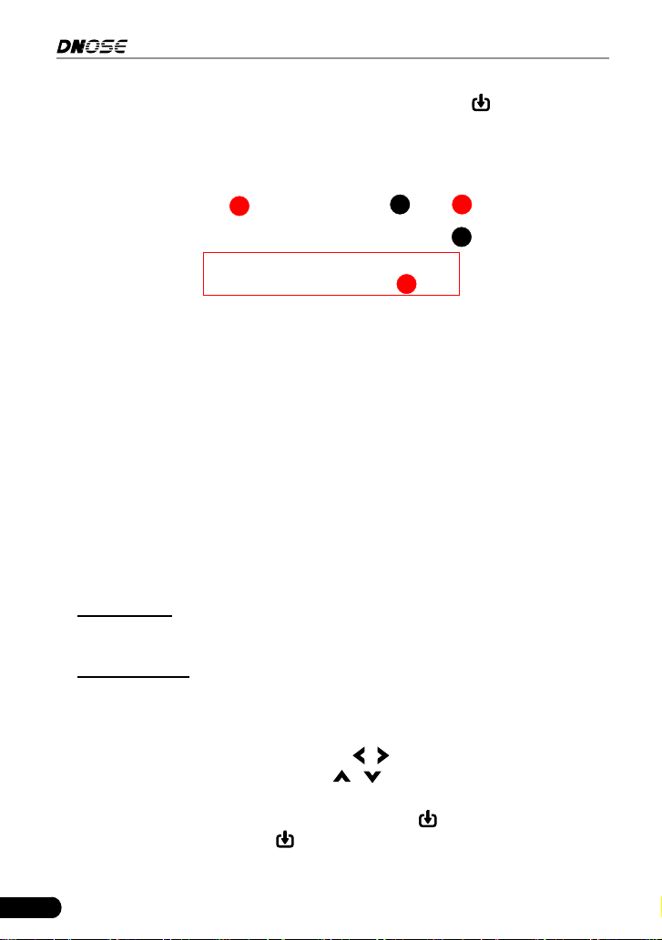
1) Take out the TF card from package box.
2) Insert the TF card into the TF card slot of the tool perpendicularly. Make sure
is fully inserted in the right place with the “micro” label facing upward.
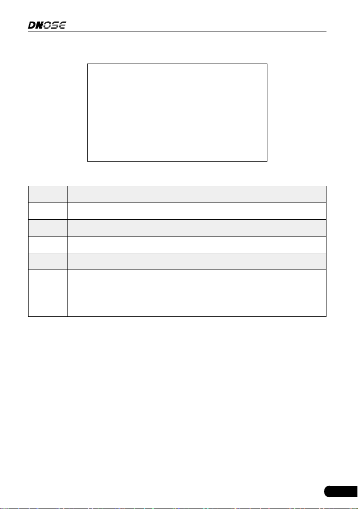
4.2 Vehicle connection
1. Turn the ignition off.
2. Locate the vehicle’s 16-pin Data Link Connector (DLC).
3. Plug one end of the diagnostic cable into DB-15 connector of the tool and the
other end to the vehicle’s DLC port.

21
DN606 Automotive Diagnostic Tool User's Manual
Notes:
• A plasc DLC cover may be found for some vehicles and you need to remove it
before plugging the diagnosc cable.
• The cable connector is keyed and will only t one way. If you have problems
connecng the cable connector to the DLC, rotate the connector 180
o
and try
again.
4. Turn the ignition on. Engine can be off or running.
CAUTION: Don’t connect or disconnect any test equipment with ignion on
or engine running.
5. The system automatically turns on and navigates to the Main Menu screen.

22
DN606 Automotive Diagnostic Tool User's Manual
5. Diagnose
Select [Diagnose] on the home screen and press , the following screen will
appear:
Figure 5-1
5.1 OBDII/EOBD Diagnosing
This option presents a quick way to check for DTCs, isolate the cause of the
illuminated Malfunction Indicator Lamp (MIL), check monitor status prior to
emissions certification testing, verify repairs, and perform a number of other
services that are emission-related.
In Figure 5-1, highlight [OBD II/EOBD] and press
. The tool will automatically
start a check of the vehicle’s computer to determine which type of communication
protocol it is using. When the tool identifies the computer’s communication
protocol, a communication link is established and then the screen will display the
Monitor Status.
Note: A PROTOCOL is a set of rules and procedures for regulang data
transmission between computers, and between tesng equipment and computers.
Now ve dierent types of protocols (ISO 9141, Keyword 2000, J1850 PWM, J1850
VPW and CAN) are in use by vehicle manufacturers.

23
DN606 Automotive Diagnostic Tool User's Manual
Figure 5-2
Press
, the following diagnostic menu will appear:
Figure 5-3
Note: If it fails to enter the system, the message box prompng error in
communicaon with vehicle ECU will pop up on the screen. Follow the on-screen
instrucons to check the possible cause and retry it.
5.1.1 Read Codes
This function allows you to view the Diagnostic Trouble Codes (DTCs) retrieved
from the vehicle’s on-board computer.
Note: Retrieving and using DTCs for troubleshoong vehicle operaon is only one
part of an overall diagnosc strategy. Never replace a part based only on the DTC
denion. Each DTC has a set of tesng procedures, instrucons and ow charts that
must be followed to conrm the locaon of the problem. This informaon can be
found in the vehicle’s service manual.
24
DN606 Automotive Diagnostic Tool User's Manual
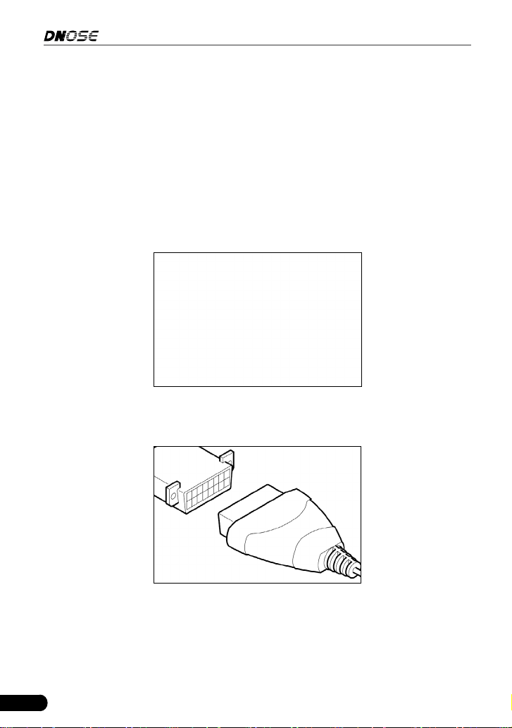
Select [Read Codes] from the Diagnostic Menu and press . The system will
automatically read the SAE-standard DTCs and a screen similar to Figure 5-4
will appear.
A
B C
D
E
Figure 5-4
In Fig. 5-4,
• A - DTC: Displays the Diagnostic Trouble Code (DTC) number. Each fault is
assigned a code number that is specic to that fault.
• B - Code Number Sequence: The tool assigns a sequence number to each
DTC that is present in the computer’s memory, starting with “1.” This number
indicates which code is currently displayed.
• C - Code Enumerator: Indicates the total number of codes retrieved from the
vehicle’s computer.
• D - Code Type: Indicates the type of code being displayed: Generic Current,
Generic Pending, Generic Permanent, etc.
Pending DTC: A code recorded on the “rst trip” for a “two-trip” code. If the
fault that caused the code to be set is not detected on the second trip, the
code is automatically erased.
Permanent DTC: It indicates there is a problem in one or more of the vehicle’s
systems. In this case, the Malfunction Indicator (“Check Engine”) lamp on the
vehicle’s instrument panel will light steady on.
• E - Test Data Display Area: Displays DTC denitions.
If more than one DTC was retrieved, press
/ to view different DTCs.
In the case of long code denitions, use
/ to view the additional
information.
If the record mode in the tool setup is set as ON, the
button will appear on
the bottom of the screen. Press
to record the diagnostic trouble code for later
printing. The saved records are stored in “Print” in the Main Menu.
25
DN606 Automotive Diagnostic Tool User's Manual
Press
to view the diagnostic tips/solution associated with the current DTC.
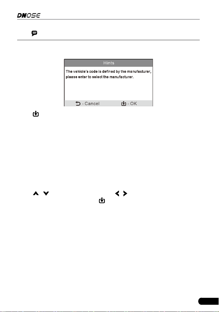
Note: In case the diagnostic codes are manufacturer-specific, users need to
select the manufacturer manually and the following screen will display.
Press
to enter to select the manufacturer.
Press
/
to select dierent items; press
/
to turn to next or previous page.
Aer selecng the desired one, press
to conrm.
• If some DTCs are found, the screen will display the DTCs (Refer to Figure 5-4).
• If the DTC can not be found, a screen similar to the following gure will appear:
26
DN606 Automotive Diagnostic Tool User's Manual
5.1.2 Erase Codes
Note: When this function is used to erase DTCs from the vehicle’s on-board
computer, “Freeze Frame” data is erased and “Permanent” DTCs ARE NOT erased.
If you plan to take the vehicle to a Service Center for repair, DO NOT erase the
codes from the vehicle’s computer. If data is erased, valuable information that
might help the technician troubleshoot the problem will also be erased.
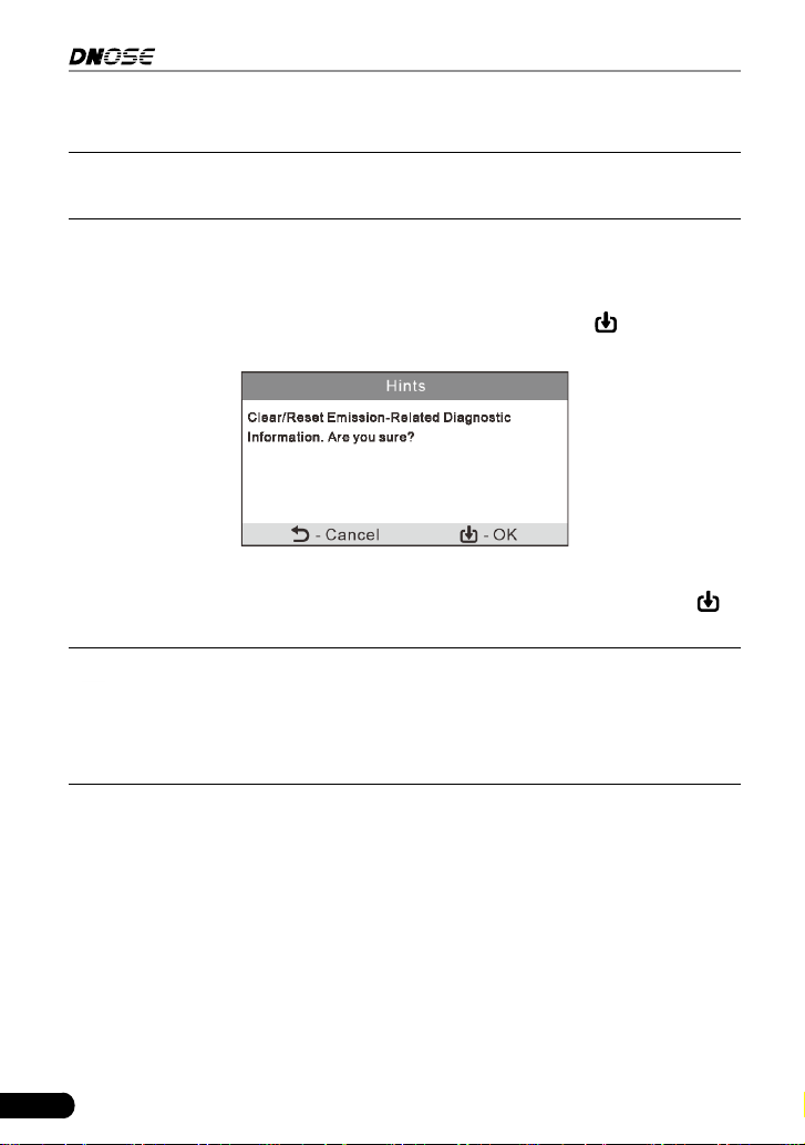
Select [Erase Codes] from the Diagnostic Menu and press
, the following
screen will appear:
Figure 5-5
Follow the on-screen prompts to turn the ignition on with engine off, press
to
clear the DTCs.
Note: When data is erased from the vehicle’s computer memory, the I/M
Readiness Monitor Status program resets the status of all Monitors to a “Not
Completed” status. To set all of the Monitors to a “Completed” status, an OBD
II Drive Cycle must be performed. Refer to your vehicle’s service manual for
informaon on how to perform an OBD II Drive Cycle for the vehicle under test.
After clearing, you should retrieve trouble codes once more or turn ignition on
and retrieve codes again. If there are still some trouble codes in the system,
please troubleshoot the code using a factory diagnosis guide, then clear the
code and recheck.
5.1.3 I/M Readiness
I/M refers to Inspection and Maintenance that is legislated by the Government
to meet federal clean-air standards. I/M Readiness indicates whether or not the
various emissions-related systems on the vehicle are operating properly and are
ready for Inspection and Maintenance testing.
The purpose of the I/M Readiness Monitor Status is to indicate which of the

27
DN606 Automotive Diagnostic Tool User's Manual
vehicle’s Monitors have run and completed their diagnosis and testing, and
which ones have not yet run and completed testing and diagnosis of their
designated sections of the vehicle’s emissions system.
The I/M Readiness Monitor Status function also can be used (after repair of
a fault has been performed) to confirm that the repair has been performed
correctly, and/or to check for Monitor Run Status.
Select [I/M Readiness] from the Diagnostic Menu and press
, the screen will
display the I/M readiness result.
Figure 5-6
N/A means not available on this vehicle; INC means incomplete or not ready and
OK means Completed or Monitor Ok.
5.1.4 Data Stream
This option retrieves and displays live data and parameters from the vehicle’s
ECU.
Select [Data Stream] from the Diagnostic Menu and press
, the following
screen appear:

28
DN606 Automotive Diagnostic Tool User's Manual
Figure 5-7
• Select [View All Items] and press
, the screen will display the dynamic data
of all data stream items:
Figure 5-8
Press
/ to turn page to view other data streams.
• Select [Select Items] in Data stream menu and press
, the screen will
display the interface as shown below:
Figure 5-9
Press
/ to check data stream items, and press / to turn page.
After selecting items, press
, the screen will display the selected data
stream items.
To select all data stream of the current page, check the option “All Datastream
of Page” and press
, √ will appear before all items. To deselect all, just
press
again.

29
DN606 Automotive Diagnostic Tool User's Manual
• If [View Graphic Items] is selected in Data stream menu and press
to enter
the graphic items selection screen.
Press
/ to select single data stream items, and press , the screen will
display the selected items of live graphic data.
5.1.5 View Freeze Frame
When an emission-related fault occurs, certain vehicle conditions are recorded
by the on-board computer. This information is referred to as freeze frame data.
Freeze Data is a snapshot of the operating conditions at the time of an emission-
related fault.
Note: if DTCs were erased, Freeze Data may not be stored in vehicle memory
depending on vehicle.
5.1.6 O2 sensor test
OBD II regulations require that applicable vehicles monitor and test operation
of the oxygen (O
2
) sensors to identify problems that can affect fuel efficiency
and vehicle emissions. These tests are performed automatically when engine
operating conditions are within predefined limits. Results of these tests are
stored in the on-board computer’s memory.
The O2 Sensor Test function lets you retrieve and view O2 sensor monitor
test results for the most recently completed tests from your vehicle’s on-board
computer.
5.1.7 On-board monitor test
The On-board Monitor Test function retrieves and displays test results for
emission-related powertrain components and systems that are not continuously
monitored. The tests available are determined by the vehicle manufacturer.
5.1.8 EVAP System Test
The EVAP test function lets you initiate a leak test for the vehicle’s EVAP system.
This tool does not perform the leak test, but signals to vehicle’s on-board
computer to initiate the test. The vehicle manufacturer determines the criteria
and method for stopping the test once it has been started. Before using the
system test function, refer to the vehicle’s service repair manual to determine the
procedures necessary to stop the test.

30
DN606 Automotive Diagnostic Tool User's Manual
5.1.9 Vehicle Info
Select [Vehicle Info] from the Diagnostic Menu and press , the tool will retrieve
a list of information (provided by the vehicle manufacturer) from the vehicle’s on-
board computer. This information may include:
• VIN (Vehicle identication Number). It is applicable to model year 2000 and
newer OBD II-compliant vehicles.
• CID (Calibration ID). These IDs uniquely identify the software version(s) for
the vehicle’s control module(s).
• CVN (Calibration Verication Number). CVNs are used to CVNs are used to
determine if emission-related calibrations for the vehicle under test have been
changed. One or more CVNs may be returned by the vehicle’s computer.
5.2 System Diagnosing
This function is specially designed to diagnose electronic control system of
single vehicle model which includes the following systems:
• ENG (Engine)
• ABS (Anti-lock Brake System)
• TCM (Transmission Control Module)
• SRS (Supplemental Restraint System)
Notes:
• Before diagnosing, please make sure the diagnostic program corresponding to
certain vehicle model has been installed on the tool.
• For vehicles manufactured by dierent vendors, it is possible that it has dierent
diagnostic menus. For details, please follow the instructions on the screen to
proceed.
On the home screen, select [Diagnose] and press
, the following screen will
appear.

31
DN606 Automotive Diagnostic Tool User's Manual
Figure 5-10
Highlight [Scan] and press
, the system will enter vehicle system selection
interface.
Figure 5-11
Refer to the owchart illustrated as below to diagnose a vehicle manually
.

32
DN606 Automotive Diagnostic Tool User's Manual
Select “Scan”
Automatic
(Note: This mode allows
your tool to scan the
vehicle test system
automatically)
Manual Select
(Note: In this case, you need to choose
the desired system manually. Just
follow the on-screen instructions to
proceed.)
Select test system
Select test function
Select Vehicle Model
(Note: For different
vehicles, vehicle make
selection may differ.
Generally, we can choose
a vehicle via make year.
But for BENZ, we need to
choose it via chassis.)
Select Vehicle
Manufacturer
Read version
information
Read fault code
Clear fault code
Read data
stream
5.3 Review
This function is used to review or delete the recorded DTC, Data Streams and
Freeze Frame, and upload the record.
For details on how to record, please refer to “Chapter 6.4 Record Mode”.
Highlight [Diagnose] on the home screen screen and press
to enter the
submenu of Diagnose.
Highlight [Review] and press
to enter review options selection interface:

33
DN606 Automotive Diagnostic Tool User's Manual
Figure 5-12
Select the desired option and press
to perform the corresponding function.

34
DN606 Automotive Diagnostic Tool User's Manual
6 Settings
Select [Settings] on the home screen and press , the system will enter the
following screen:
Figure 6-1
6.1 Language
This option enables you to set the user interface language.
Due to continuous software upgrade, language interface may differ from different
software versions.
6.2 Unit of Measure
This option allows you to set measurement unit.
6.3 Beeper
It is used to set On/Off the buzzer.
6.4 Record Mode
It is used to turn On/Off recording function.
When recording is ON, the icon
appears, then the tool can record DTCs, Data
Stream and Freeze Frames.

35
DN606 Automotive Diagnostic Tool User's Manual
7. Help
This menu enables you to view device information and OBD introduction.
On the home screen, select [Help] and press
to enter the following screen.
Figure 7-1
7.1 DLC Location Information
This option allows you to check the location of vehicle’s DLC.
7.2 DTC Library
This option provides abundant diagnostic trouble code database for your quick
retrieval.
Select [DTC Library] and press
to enter the following screen.
Figure 7-2
Press
/ to move the highlight bar to different position. Press / to alter
36
DN606 Automotive Diagnostic Tool User's Manual
the value, then press
, the screen will display denition of the DTC.
7.3 Abbreviation
This option provides the detailed descriptions to some vehicle glossary
abbreviations for your reference.
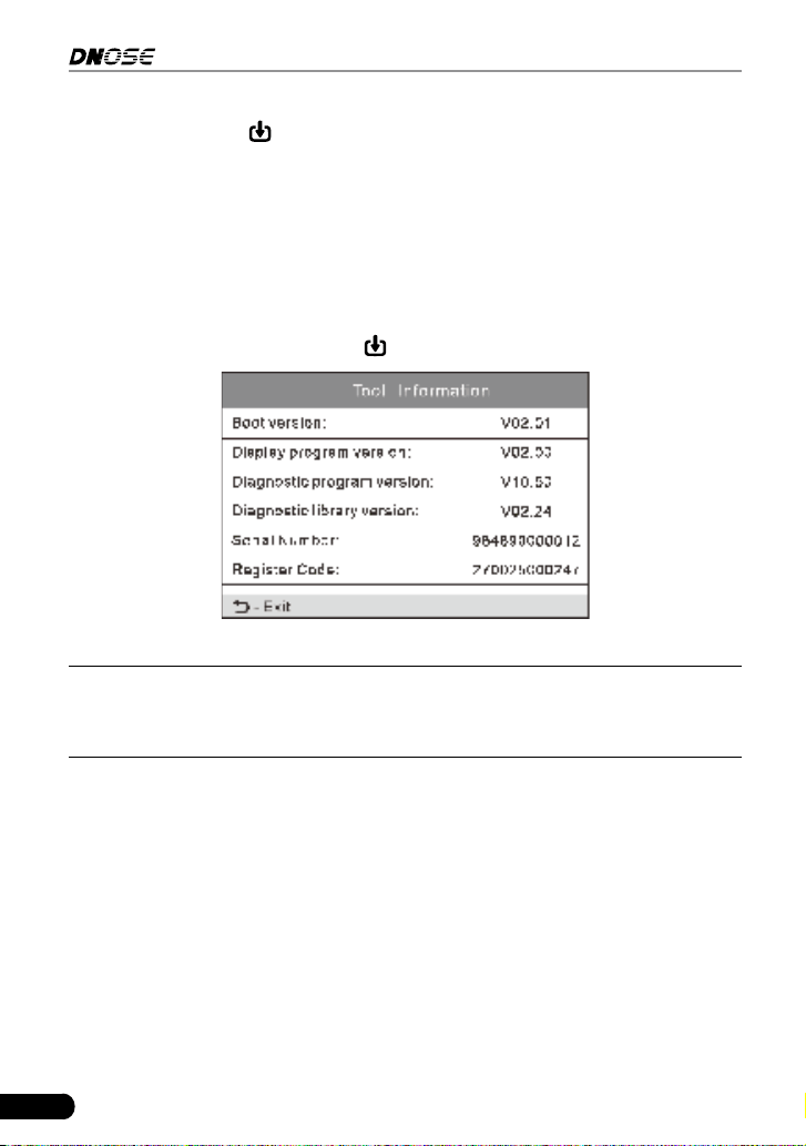
7.4 Tool Information
This option lets you check the detailed information of the tool.
Select [Tool Information] and press
to view the related information of the tool.
Figure 7-3
Note: You are strongly recommended to note down the Serial Number and
Register Code since these 2 pieces of informaon are required while registering your
tool.
7.5 About OBD
This option allows you to have a general knowledge of OBD.

37
DN606 Automotive Diagnostic Tool User's Manual
8. Update & Print
8.1 Register & Update
Hardware Requirement:
1. A computer that can access the Internet.
2. A TF card reader/writer and a TF card.
Follow the steps described as below to proceed registration and update:
1. Go to http://www.dnosetech.com.
2. Download and install the update tool and launch the program when installed.
3. You will be prompted to type in the Serial Number (located on the back of the
tool).
Figure 8-1
4. After the Serial Number is entered, click Device upgrade and enter the
following information. Click “Submit.”
Figure 8-2
(If you need the Register Code, proceed to the steps 5-8.)
(If you have the Register Code, proceed to step 9 directly.)

38
DN606 Automotive Diagnostic Tool User's Manual
5. The Register Code can be found by connecting the supplied USB cord to the
tool and inserted into the computer.
6. When the tool has powered up, highlight the [Help] icon and press
.
Figure 8-3
7. Select [Tool Information], press
.
Figure 8-4
8. This is the Register Code number for inputting into Step 4.

39
DN606 Automotive Diagnostic Tool User's Manual
Figure 8-5
(Return to step 4 and input the code and then proceed)
9. Install the TF card from the tool into the supplied TF card reader and insert
into USB port of PC.
10.Reopen the update Suite and select the updates you would like to preform or
click “Select All” and click “Download”.
11. Once all steps are complete, reinsert the TF card into the tool and power the
tool via USB in computer or via OBD II port in vehicle. The tool will prompt
you to upgrade, click “OK” to start updating and a progress bar will appear. It
may takes several minitues to nish update if your upgrade package le is too
large, please wait.
12.The registration process is now complete.
8.2 Print
This function is used to print the recorded DTC, datastream and freeze frame.
Note: Print manager is integrated in the update tool. To perform this funcon,
you need to download the update tool and install it on the computer.
1. Connect the tool to the computer via USB cable.
2. Launch the update tool on the computer.

40
DN606 Automotive Diagnostic Tool User's Manual
Figure 8-6
3. Click [Print Manager] to enter the print manager screen.
4. Select [Diagnose] -> [Review] and press
to enter the following screen.
Figure 8-7
5. Select [Upload Record] to enter the record list screen. Select the desired
record and press
.
6. The print manager will synchronize the record with the tool and display it on
the computer.

41
DN606 Automotive Diagnostic Tool User's Manual
Figure 8-8
7. Click the
button to print it out via the printer connected to the computer.

42
DN606 Automotive Diagnostic Tool User's Manual
9. FAQ
Here we list some frequently asked questions and answers relating to the tool.
Question: System halts when reading data stream. What is the reason?
Answer: It may be caused by a slackened connector. Please turn off the tool,
rmly connect the connector, and switch on it again.
Question: Screen of main unit ashes at engine ignition start.
Answer: Caused by electromagnetic disturbing, and this is normal phenomenon.
Question: There is no response when communicating with on-board computer.
Answer: Please confirm the proper voltage of power supply and check if the
throttle has been closed, the transmission is in the neutral position, and the
water is in proper temperature.
Question: Why are there so many fault codes?
Answer: Usually, it’s caused by poor connection or fault circuit grounding.

43
DN606 Automotive Diagnostic Tool User's Manual
Warranty
This electronic product is warranted against defects in materials and
workmanship for one year (12 months) from date of delivery to the user.
This warranty does not cover any part that has been abused, altered, used for a
purpose other than for which it was intended, or used in a manner inconsistent
with instructions regarding use. The exclusive remedy for any automotive meter
found to be defective is repair or replacement, and we shall not be liable for any
consequential or incidental damages.
Customer Service
If you have any questions on the operation of the unit, please contact:
E-mail: [email protected]
Address: D2, A DONG, WANZHONG RUNFENG PIONEER PARK,, NO.
973, MINZHI AVENUE XINNIU COMMUNITY, MINZHI STREET, LONGHUA,
DISTRICT SHENZHEN CHINA
Website: www.dnosetech.com
