Loading ...
Loading ...
Loading ...
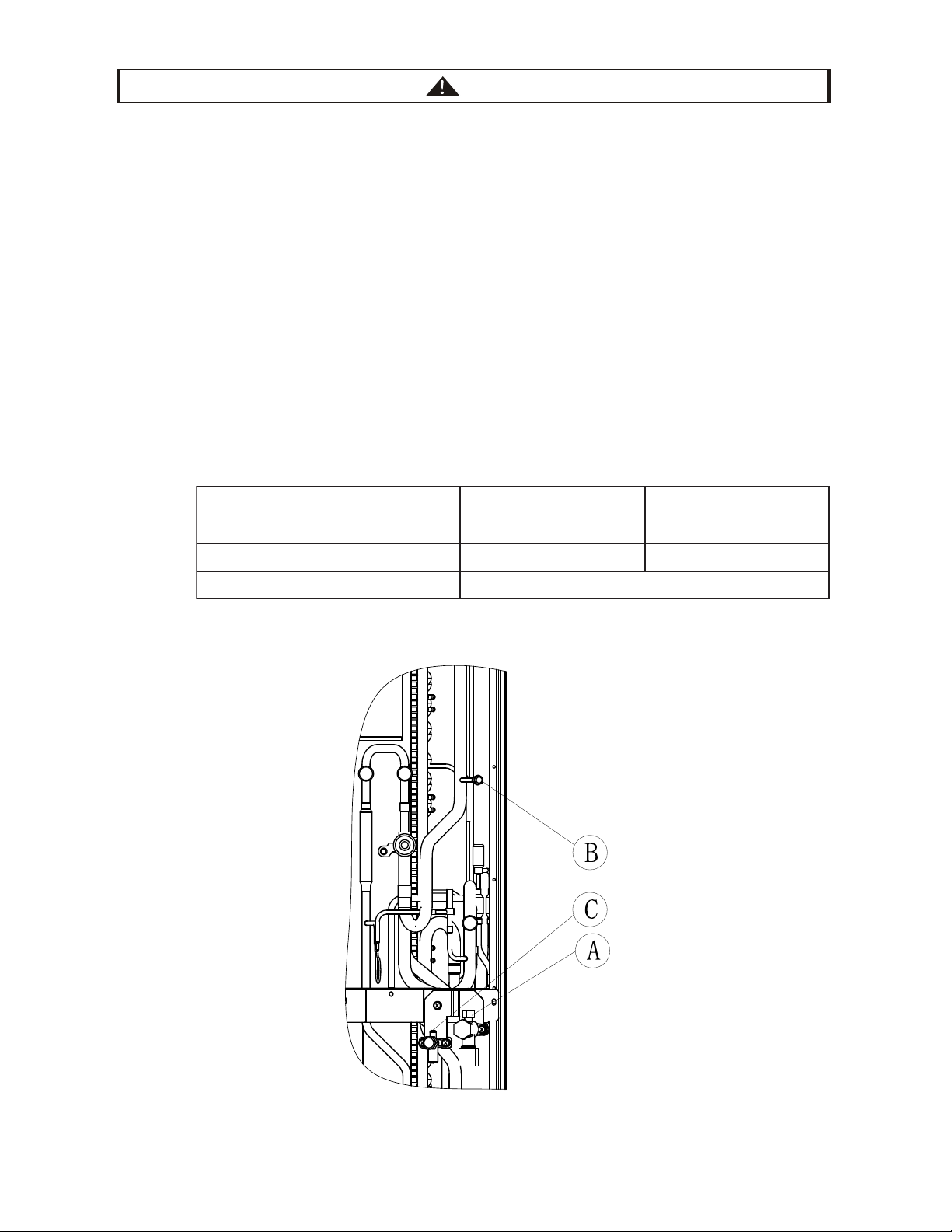
5.7 Caution of the Pressure by Check Joint
When the pressure is measured, use the check joint of gas stop valve ((A) in the figure below) and use the
check joint of liquid piping ((B) in the figure below).
At that time, connect the pressure gauge according to the following table because of high pressure side and
low pressure side changes by operation mode.
Cooling Operation Heating Operation
Check Joint for Gas Stop Valve "A" Low Pressure High Pressure
Check Joint for Piping "B" High Pressure Low Pressure
Check Joint for Liquid Stop Valve "C"
NOTE:
Be careful that refrigerant and oil do not splash onto the electrical parts when removing the charge
hoses.
Exclusive for Vacuum Pump and Refrigerant Charge
16
Fig 5.4 Check Joint Position
1.
Maximum Permissible Concentration of HFC GAS R410A
The refrigerant R410A is an incombustible and non-toxic gas.
However, if leakage occurs and gas fills a room, it may cause suffocation.
lkg t mt t tk fft t t mk t tt f l
t lbft
3
( kgm
3
)
Calculation of Refrigerant Concentration
(1) Calculate the total quantity of refrigerant R (lb(kg)) charged in the system connecting all the
indoorunits of tgt rooms.
(2) Calculate the room this unit (ft
3
(m
3
)).
Calculate the refrigerant concentration C (lbft
3
) (kg/m
3
) of the room according to the equation.
2.
CAUTION
3.
Loading ...
Loading ...
Loading ...