Owner's Manual
ICRRFTSMRH°J
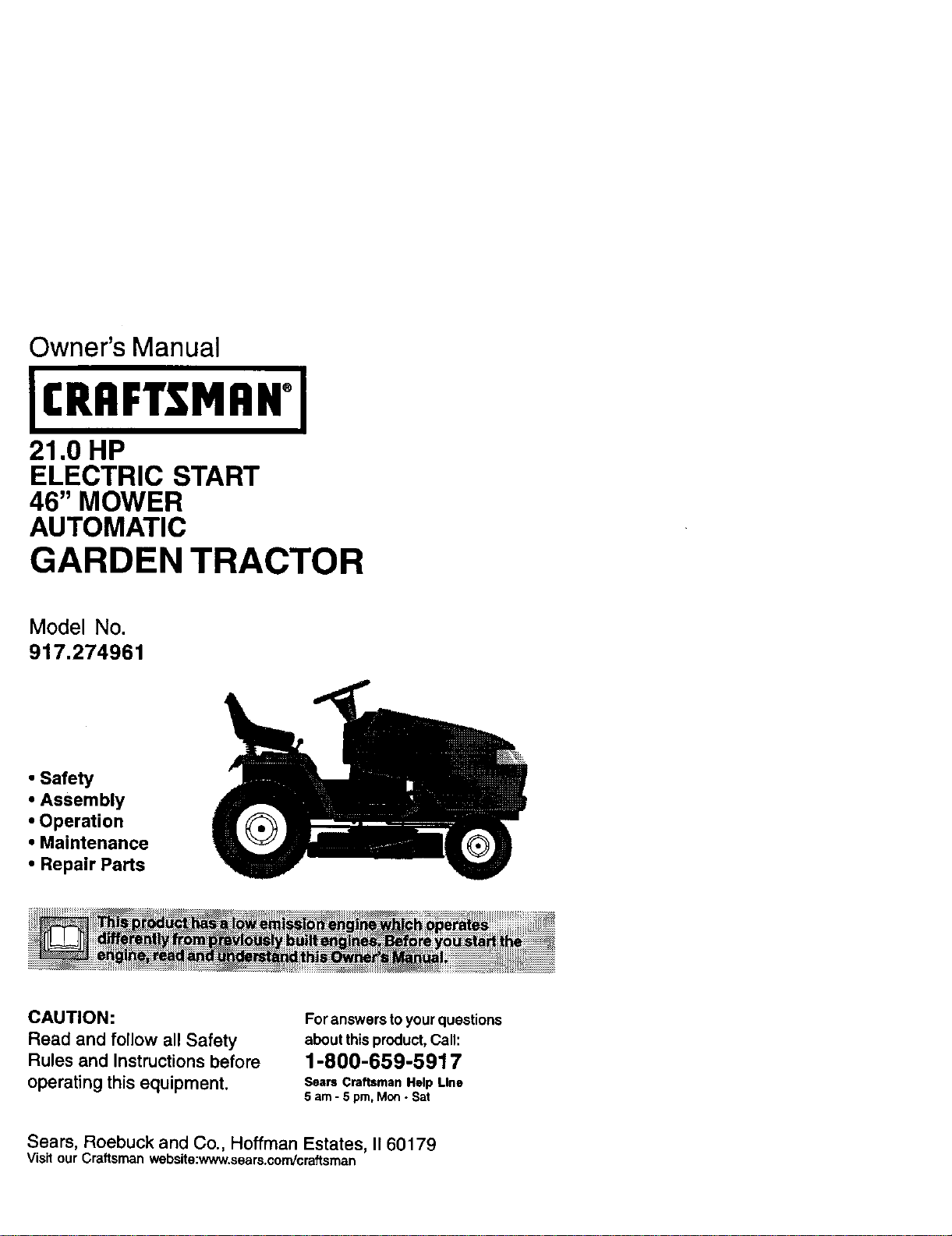
21.0 HP
ELECTRIC START
46" MOWER
AUTOMATIC
GARDEN TRACTOR
Model No.
917.274961
• Safety
• Assembly
• Operation
• Maintenance
• Repair Parts
CAUTION:
Read and follow all Safety
Rules and Instructions before
operating this equipment.
For answers toyourquestions
aboutthis product,Call:
1-800-659-5917
Sears Craftsman Help Line
5 am - 5 pm, Mon. Sat
Sears, Roebuck and Co., Hoffman Estates, II 60179
Visit our Craftsman website:www, sears.com/craftsman
Warranty ............................................... 2
Safety Rules ......................................... 3
Product Specifications .......................... 6
Assembly .............................................. 8
Operation ............................................ 12
Maintenance ....................................... 19
Maintenance Schedule ...................... 19
Service and Adjustments .................... 23
Storage ............................................... 31
Troubleshooting ................................. 32
Repair Parts ........................................ 36
Parts Ordedng ..................... Back Cover
LIMITED TWOYEAR WARRANTY ON CRAFTSMAN RIDING EQUIPMENT PARTS
For two (2) years from the dute of purchase, ff this Craftsman Riding Equipment is
maintained, lubricated and tuned up according to the instructions in the owner's
manual, Sears will repair or replace, free of charge, any parts found to be defective in
material or workmanship. Warranty service Is available free of charge by returning your
Craftsman riding equipment to your nearest Sears Service Center. In-home warranty
service is available but a trip charge will apply. This warranty applies only while this
product Is in the United States.
This Warranty does not cover:
• Expendable items which become worn dudng normal use, such as blades, spark
plugs, air cleaners, belts and oil filters.
• Tire replacement or repair caused by punctures from outside objects, such as nails,
thorns, stumps, or glass.
• Repairs necessary because of operator abuse, including but not limited to, damage
caused by towing objects beyond the capability of the ridingequipment, impacting
objects that bend the frame or crankshaft, or over speeding the engine.
• Repairs necessary because of operator negligence, including but not limited to,
electrical and mechanical damage caused by improper storage, failure to use the
proper grade and amount of engine oil,failure to keep the deck clear of flammable
debris, or the failure to maintain the equipment according to the instructionscon-
tained in the owner's manual.
• Engine (fuel system) cleaning or repairs caused by fuel determined to be contami-
nated or oxidized (stale). In general, fuel should be used within thirty (30) days of its
purchase date.
• Riding equipment used for commercial or rental purposes. A product is "used for
commercial purpose" if is used for any purpose other than single family household
dwellings or in usage where profit Is made.
LIMITED 90 DAYWARRANTY ON BATTERY
For ninety (90) days from date of purchase, if any battery included with this dding
equipment proves defective in meterial or workmanship and our testing determines the
bafterywill not holda charge, Sears will replace the batteryat no charge. Warranty
service is available free of charge by rutuming your Craftsman riding equipment to
your nearest Sears Service Center. In-home warranty service is available but a trip
charge will apply.This warranty applies only while this product is in the United States.
TO LOCATE THE NEAREST SEARS SERVICE CENTER OR TO SCHEDULE IN-HOME
WARRANTY SERVICE, SIMPLY CONTACT SEARS AT 1-800-4-MY-HOME
This Warranty gives you specific legal dghts, and you may also have other rights which
may vary from state tostate.
Sears, Roebuck and Co., D/817 WA, Hoffman Estates, IL 60179
2
IMPORTANT: This cutting mach ne is capable,of amputating han.ds and tae_t_d.
throwingobjects. Failure to observe the following safety mstrusnons coU,u resu m
serious injury or death.
I. GENERAL OPERATION
• Read, understand,and follow all
instructionsin the manual and on the
machine before starting.
• Only allow responsibleadults,who are
familiarwiththe instructions,tooperate
the machine.
• Clear the area ofobjects suchas rocks,
toys,wire, etc., whichcould be picked
upand thrownby the blade.
• Be surethe area is dear ofother people
beforemowing. Stop machine if anyone
entersthe area.
• Never carry passengers.
• Do not mow in reverse unlessabsolutely
necessary. Always look down and
behind before and while backing.
• Be aware of the mowerdisuharge
directionand do not pointit at anyone.
Do not operate the mower withouteither
the entire grasscatcheror the guard in
place.
• Slow down before turning.
• Never leave a runningmachine
unattended. Always bJmoffblades, set
perking brake, stop engine, and remove
keys before dismounting.
• Turn off blades whan notmowing.
• Stop engine before removinggrass
catcher or uncloggingchute.
• Mow onlyin daylightor goodartificial
light.
• Do not operate the machine while under
the influenceof alcohol or drugs.
• Watch fortrafficwhen operating near or
crossing roadways.
• Use extra care when loading or unload-
ingthe machine intoa trailerortruck.
• Data indicatesthat operators,age 60
years and above, are involvedin a large
percentage of riding mower-related
injuries. These operatorsshoa_d
evaluate their abilityto operate the riding
mower safelyenough to protectthem-
selvesand others from sedouainiury.
• Keepmachine free ofgrass, leavesor
other debris build-upwhich can touch
hotexhaust / engine parts end bum. Do
notallow the mower deck to plow leaves
or other debris which can cause build-
upto occur. Clean any oil or fuel
spillagebefore operating or stor_g the
machine. Allow machine to cool before
storage.
II. SLOPE OPERATION
Slopes are a major factor related to loss-of-
control and tipoveraccidents, whichcan re-
suit in severe injury or death. All slopes
require extra caution, ff you cannolback Up
the slope or if you feel uneasy on it, do not
mow it.
DO:
• Mow up and down slopes,not across.
• Remove obstaclessuchas rocks, tree
limbs,etc.
• Watch forholes, ruts,or bumps. Uneven
terrain couldoverturn the machine. Tall
grass can hide obstacles.
• Use slow speed. Choose a low gear so
that you willnot have to stopor shift
while on the slope.
,, Follow the manufacturer's recommenda-
tionsfor wheel weights or counter-
weights to improve stability.
• Use extra care with grasscatchersor
other attachments. These can change
the stabilityof the machine.
• Keep all movement on the slopes slow
and gradual. Do not make sudden
changes in speed or direction,
• Avoid starting or stopping on a slope. If
tires lose trection, disengage the blades
and proceed slowlystraight down the
slope.
DO NOT:
• Do not turn on slopesunless necessary,
and then, tam slowlyand gradually
downhill,ff possible.
• Do net mow near dmp-offs, ditches,or
embankments. The mower could
suddenly tam over if a wheel isover the
edge of astiff or ditch, or ifan edge
caves in.
• Do not mow onwet graSS.Reduced
trac_on could cause sliding.
• Do not try to stabilizethe machine by
puttingyourfoot on the ground.
• Do notuse grass catcher on steep
slopes.
3
IU. CHILDREN
Tragicaccidents can occurif the operator
isnotalert tothe presence ot childmn.
Children are often attracted to the
machine and the mowing activity. Never
assume 1hat children will remain where
you last saw them.
• Keep children out of the mowing area
and under the watchful care of another
responsible adult.
• Be alert and turn machine off it children
enter the area.
• Before and when backing, look behind
and down for small children.
• Never carry children. They may fait oll
and be seriously injured or interfere
with safe machine operation.
• Never allow children to operate the
machine.
• Use extra care when approaching blind
comers, shrubs,trees, or other objects
that may obscure vision.
IV. SERVICE
= Use extra care in handling gasoline
and other fuels. They are flammable
and vapors are explosive.
- Use only an approved container.
- Never remove gas cap or add fuel
with the engine running. Allow
engine to cool before refueling. Do
not smoke.
-Never refuel the machine indoors.
- Never store the machine or fuel
container inside where there is an
open flame, such as a water heater.
• Never run a machine inside a closed
area.
• Keep nuts and belts, especially blade
attachment bolts,tight and keep
equipment in good condition.
• Never tamper with safety devices.
Check their proper operation regularly.
• Keep machine free ofgrass, leaves, or
other debds build-up. Clean oil or fuel
spillage. Allow machine to cool before
stodng.
• Stop and inspect the equipment if you
strike an object. Repair, if necessary,
before restarting.
• Never make adjustments or repairs
with the engine running.
• Grass catcher components are subject
to wear, damage, and deterioration,
which could expose moving parts or
allow objects to be thrown. Frequently
check components and replace with
manufacturer's recommended parts,
when necessary.
• Mower blades are sharp and can cut.
Wrap the blade(s) or wear gloves, and
use extra caution when servicingthem.
• Check brake operation frequently.
Adjust and service as required.
• Be sure the area is clear of other
people before mowing. Stop machine if
anyone enters the area.
• Never carry passengers or children
even with the blades off.
• Do not mow in reverse unless abso-
lutely necessary. Always lookdown
and behind before and while backing.
• Never carry children. They may fall off
and he seriously injured or interfere
with safe machine operation.
• Keep children out of the mowing area
and under the watchful care of another
responsible adult,
• Be alert and tum machineoff if children
enter the area.
• Before and when backing, look behind
and 6own for small children.
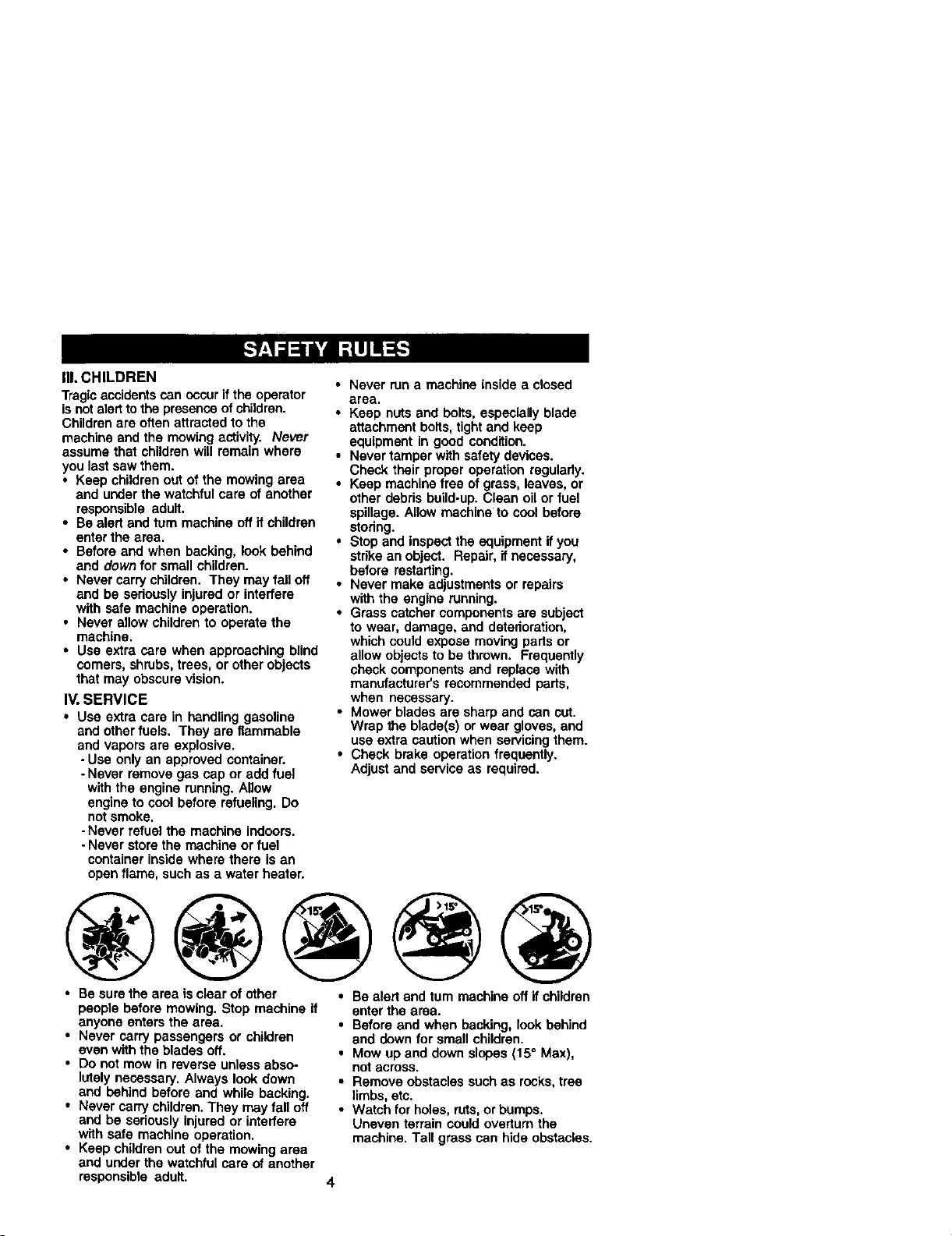
• Mow up end down slopes (15=Max),
not across.
• Remove obstacles such as rocks, tree
li_s, etc.
• Watch for holes, ruts,or bumps.
Uneven terrain could overturn the
machine. Tall grass can hide obstacles.
4
• Use slow speed. Choose a low gear so
that you will nothave to stop or shift
while on the slope.
• Avoid starling or stoppingon a slope. If
tires lose traction, disengage the
blades and proceed slowly straight
down the slope.
• If machine stops while going uphill,
disengage blades, shift into reverse
and back down slowly.
• Do nottum on slopes unless neces-
saw, and then, turn slowlyand gradu-
ally downhill, if possible.
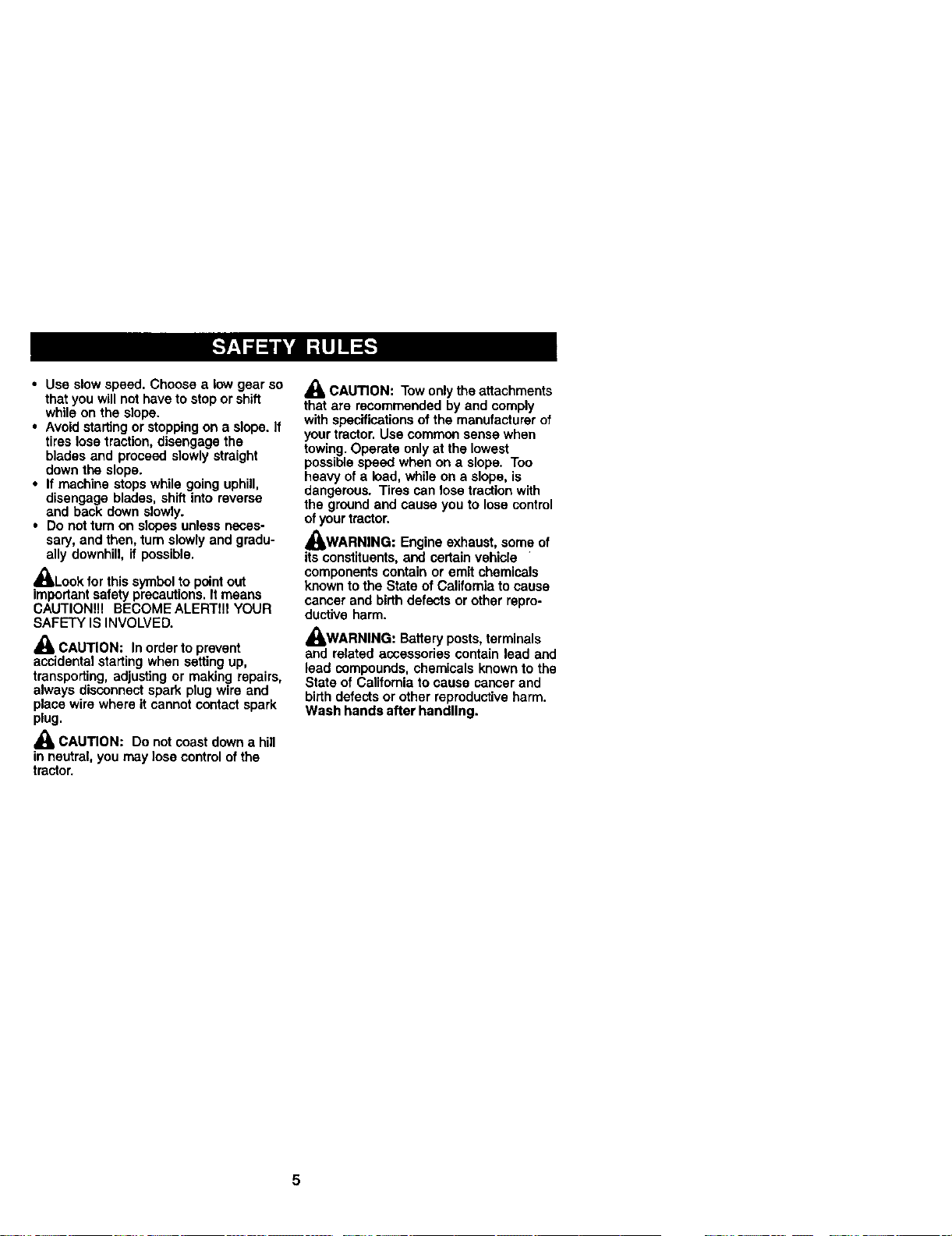
_l, Lookfor this symbol to point out
importantsafety precautions. Itmeans
CAUTION!!! BECOMEALERTIn YOUR
SAFETY IS INVOLVED.
CAUTION: In order to prevent
accidental starting when setting up,
transporting, adjusting or making repairs,
always disconnect spark plug wire and
place wire where it cannot contact spark
plug.
_, CAUTION: Do notcoast down a hill
in neutral, you may lose control of the
tractor.
CAUTION: Tow onlythe attachments
that are recommended by and comply
with specificationsof the manufacturer of
your tractor. Use common sense when
towing. Operate only at the lowest
possiblespeed when on a slope. Too
heavy ofa load, while on a slope, is
dangerous. Tires can lose tractionwith
the groundand cause you to lose control
ofyour tractor.
_WARNING: Engine exhaust, some of
its constituents,and certain vehicle
components contain or emit chemicals
known to the State of California to cause
cancer and birth defects or other repro-
ductive harm.
_WARNING: Battery posts, terminals
and related accessories contain lead and
lead compounds, chemicals known to the
State of Calitomia to cause cancer and
birth defects or other reproductive harm.
Wash hands after handling.
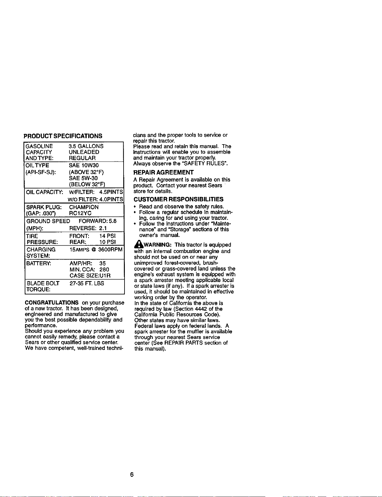
PRODUCTSPECIFICATIONS
IASOLINE 3.5 GALLONS
;APACITY UNLEADED
NDTYPE: REGULAR
OILTYPE SAE 10W30
API-SF-SJ): (ABOVE 32°F)
SAE 5W-30
(BELOW 32°F)
OIL CAPACITY: W/FILTER: 4.5PINTS
w/o FILTER: 4.0PINTS
SPARK PLUG: CHAMPION
3AP: .030") RC12YC
GROUND SPEED FORWARD: 5.8
(MPH): REVERSE: 2.1
TIRE FRONT: 14 PSI
PRESSURE: REAR: 10 PSI
CHARGING 15AMPS @ 3600RPM
;YSTEM:
BATTERY: AMP/HR: 35
MIN. CCA: 280
CASE SIZE:U1R
BLADE BOLT 27-35 FT. LBS
TORQUE:
CONGRATULATIONS on your purchase
of a new tractor. It has been designed,
engineered and manufactured to give
you the best possible dependability and
performance.
Should you experience any problem you
cannot easily remedy, please contact a
Sears or other qualified service center.
We have competent, well-trained techni-
clans and the proper tools to service or
repair this tractor.
Please read and retainthis manual. The
instructionswill enable you to assemble
and maintain your tractor properly.
Always observe the "SAFETY RULES".
REPAIR AGREEMENT
A Repair Agreement is available on this
product. Contact your nearest Sears
store for details.
CUSTOMER RESPONSIBILITIES
• Read and observe the safety rules.
• Follow a regular schedule in maintain-
ing, cadngfor and using your tractor.
• Follow the instructionsunder =Mainte-
nance" and =Storage"sections ofthis
owner's manual.
,_WARNING: This tractor is equipped
with an intemal combustion engine and
should not be used on or near any
unimproved forest-covered, brush-
covered or grass-covered land unless the
engine's exhaust system is equipped with
a spark arraster meeting applicable local
or state laws (ifany). If a spark arrestar is
used, itshould be maintained in effective
working order by the operator.
In the state of California the above is
required by law (Section 4442 of the
California Public Resources Code).
Other states may have similarlaws.
Federal laws apply on federal lands. A
spark arrester for the muffler isavailable
through your nearest Sears service
center (See REPAIR PARTS section of
this manual).
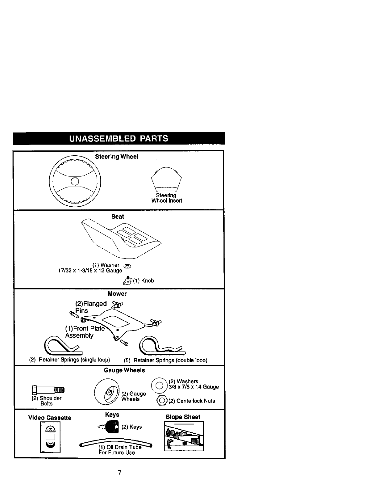
Steering Wheel
Steedng
Wheel Insert
Seat
(1) Washer
17/32 x 1-3/16 x 12 Gauge
_(1) Knob
Mower
(2)Flanged ,_
(1)Front Plate_ .'__
Assembly _
(2) Retainer Springs (single loop} (5) Retainer Springs (double loop}
Gauge Wheels
_ (2) Washers
_,Jj) 3/8 x 7/8 x 14 Gauge
(2) Gauge
v
Shoulder
_JH2) Centedock Nuts
Wheels
Bolts
Video Cassette Keys Slope Sheet
For Future Usa
7
Your newtractor has been assembled at the factory with exception of those parts left
unassembled for shippingpurposes• To ensure safe and proper operationof your
tractor all parts and hardware you assemble must be tightened securely. Use the
correct tools as necessary to insure proper tightness.
TOOLS REQUIRED FOR ASSEMBLY
A socket wrench set will make assembly
easier. Standard wrench sizes are listed.
(1) 9/16"wrench (t) Pliers
(1) 1/2"wrench (1) Utility knife
(1) 3/4" socket with
drive ratchet
(1) Tire pressure gauge
When dght or left hand is mentioned in
this manual, it means when you are in the
operating position (seated behind the
steering wheel).
TO REMOVETRACTOR FROM
CARTON
UNPACK CARTON
1. Remove all accessible loose parts
and parts cartons from carton.
2. Cut, from top to bottom, along lines on
all four comers of carton, and lay
panels flat.
3. Remove mower and packing materi-
als.
4. Check for any additional loose parts
or cartons and remove.
BEFORE REMOVINGTRACTOR
FROM SKID
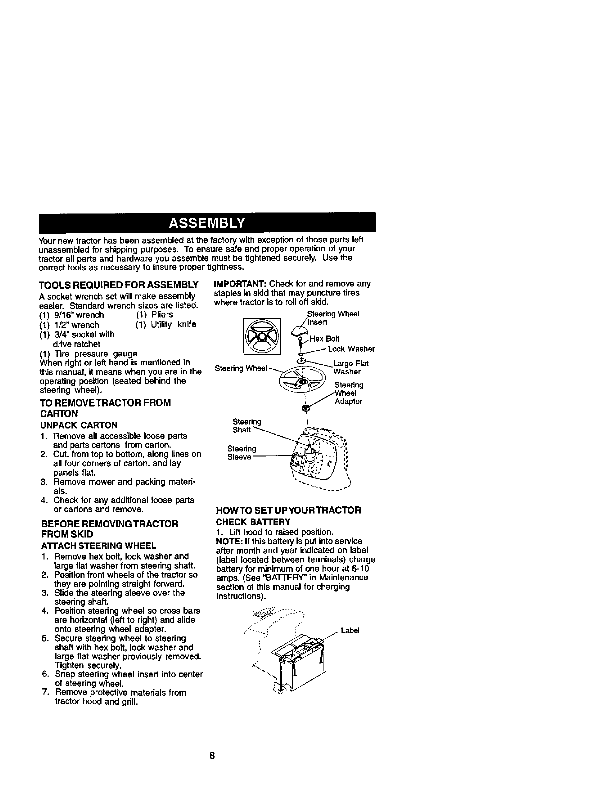
ATrACH STEERING WHEEL
1. Remove hex bolt, lock washer and
large flat washer from steering shaft.
2. Positionfront wheels ofthe tractor so
they are pointingstraight forward.
3. Slide the steering sleeve over the
steering shaft.
4. Positionsteering wheel so cross bars
are horizontal (left to right) and slide
onto steedng wheel adapter.
5. Secure steering wheel to steering
shaft with hex bolt,lock washer and
large flat washer previously removed.
Tighten securely.
6. Snap steering wheel insert intocenter
of steering wheel•
7. Remove protective materials from
tractor hood and grill.
IMPORTANT: Check for and remove any
staples in skid that may puncture tires
where tractor isto roll off skid.
Steering Wheel
,o°ort
_..Hex Bolt
'r_ LockWasher
• (_.._ LargeRat
SteenngWheel_ -Washer
.t Wheel
Adaptor
Steering I
Steenng _",;
sleeve _,_-., "_/ :,
:-d2Y\
HOWTO SET UPYOURTRACTOR
CHECK BA'I-rERY
1. Lifthood to raised position.
NOTE: If this batteryisput intoservice
after month and year indicated on label
(label located between terminals) charge
battery for minimum of one hour at 6-10
amps. (See "BATTERY"in Maintenance
section of this manual for charging
instructions).
,•'--.... : _ Label
8
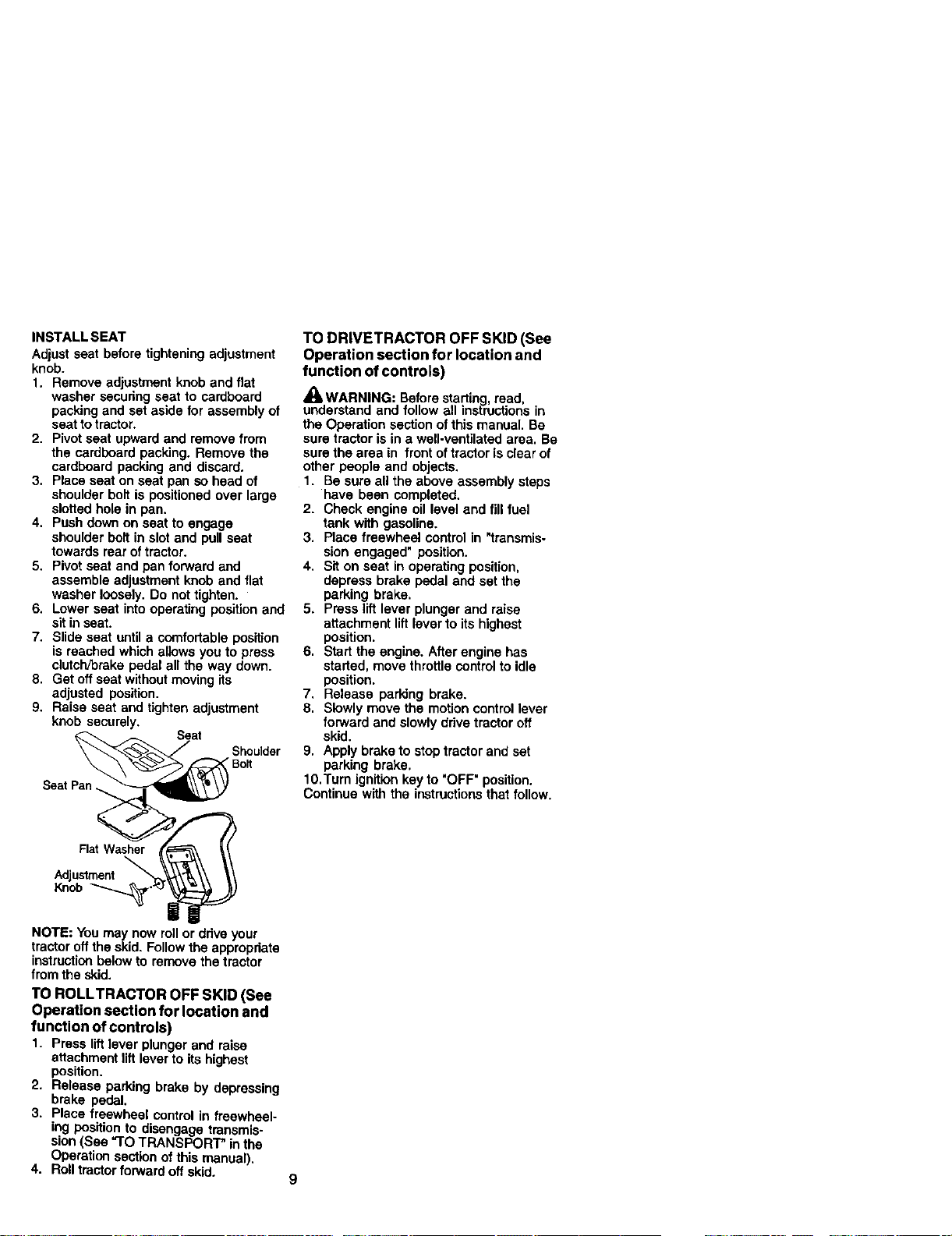
INSTALL SEAT
Adjust seat before tighteningadjustment
knob.
1. Remove adjustment knob and flat
washer secudng seat to cardboard
packing and set aside for assembly of
seat totractor.
2. Pivot seat upward and remove from
the cardboard packing. Remove the
cardboard packing and discard.
3. Place seat on seat pan so head of
shoulder bolt is positioned over large
slotted hole in pan.
4. Push down on seat to engage
shoulder boll in slot and pull seat
towards rear oftractor.
5. Pivot seat and pan forward and
assemble adjustmentknob and llet
washer loosely. Do not tighten.
6. Lower seat into operating position and
sit in seat.
7. Slide seat untita comfortabte position
is reached which allows you to press
clutch/brake pedal all the way down.
8. Get offseat without moving its
adjusted position.
9. Raise seat and tighten adjustment
knob securely.
SeatPan
TO DRIVETRACTOR OFF SKID (See
Operation section for location and
function of controls)
_II=WARNING: Beforestarting read,
understand and follow all instructions in
the Operation section of this manual. Be
sure tractor is in a well-vantilatad area. Be
sure the area in front of tractoris clearof
other people and objects.
1. Be sure all the above assembly steps
have been completed.
2. Cheek engine oil level and fill fuel
tank with gasoline.
3, Place freewheel control in "transmis-
sion engaged" position.
4, Sit on seat in operating position,
depress brake pedal and set the
parking brake.
5. Press lift lever plunger and raise
attachment lift lever to its highest
position.
6, Start the engine. After engine has
started, move throttle controlto idle
position.
7. Release parking brake.
8, Slowly move the motion control lever
forward and slowly drive tractor off
skid.
9. Apply brake to stop tractor and set
parking brake.
1O.Tum ignition key to "OFF" position.
Continue with the instructions that follow.
Flat Washer
Adjustment
Knob
NOTE: You may now roll or drive your
tractor off the skid. Follow the appropriate
instructionbelow to remove the tractor
from the skid.
TO ROLLTRACTOR OFF SKID (See
Operation section for location and
function of controls)
1. Press liftlever plunger and raise
attachment liftlever to its highest
position.
2. Release parking brake by depressing
brake pedal.
3. Place freewheel control in freewheel-
ing position to disengage transmis-
sion(See "TO TRANSPORT" in the
Operation sectionof this manual).
4. Roll tractor forward off skid.
9
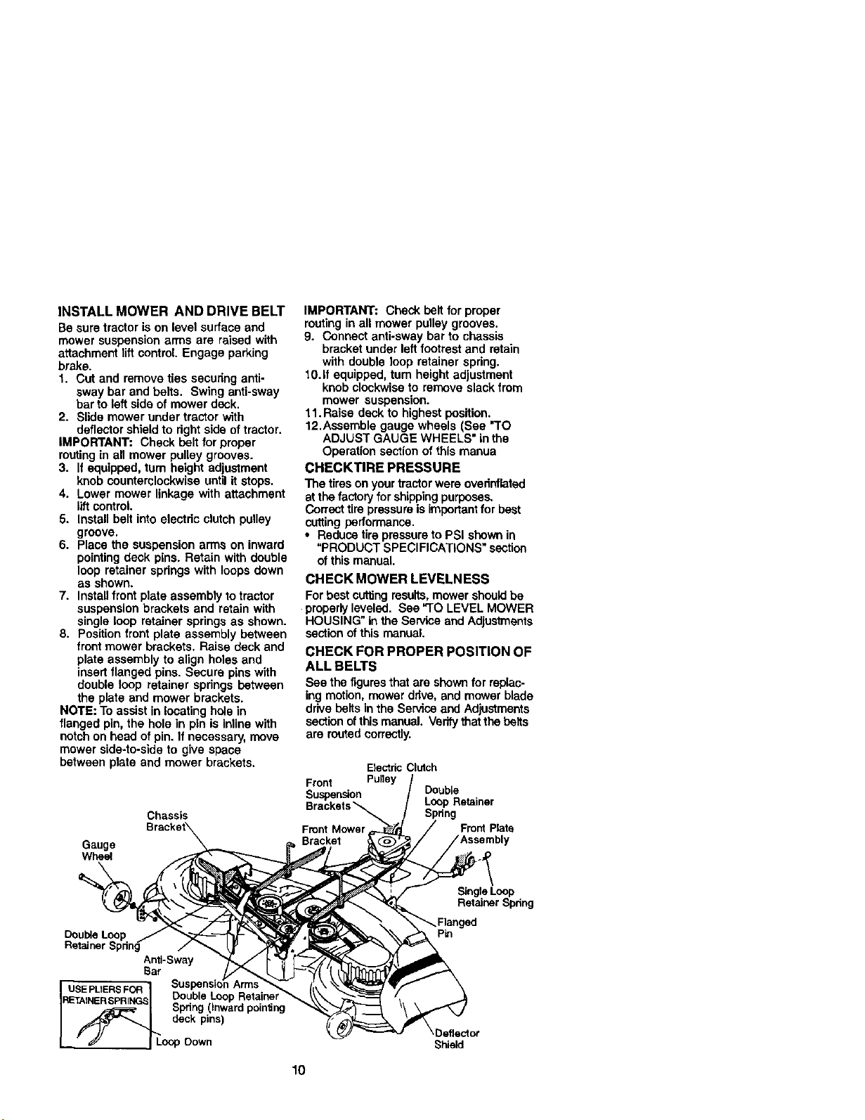
INSTALL MOWER AND DRIVE BELT
Be sure tractor ison level surface and
mower suspension arms are raised with
attachment lift control. Engage parking
brake.
1. Cut and remove ties securing anti-
sway bar and belts. Swing anti-sway
bar to left side of mower deck.
2. Slide mower under tractor with
deflector shield to rightside of tractor.
IMPORTANT: Check belt forproper
routingin all mower pulley grooves.
3. If equipped, tum height adjustment
knob counterclockwise until it stops.
4. Lower mower linkage with attachment
lift control.
5. Install belt into electric clutchpulley
groove.
6. Place the suspension arms on inward
pointingdeck pins. Retain with double
loop retainer springs with loops down
as shown.
7. Installfront plate assembly to tractor
suspensionbrackets and retain with
single loop retainer springs as shown.
8. Positionfront plate assembly between
front mower brackets. Raise deck and
plate assembly to align holes and
insertflanged pins. Secure pins with
double loop retainer springs between
the plate and mower brackets.
NOTE: To assist in locatinghole in
flanged pin, the hole in pin is inline with
notch on head ofpin. If necessary, move
mower side-to-side to give space
between plate and mower brackets.
Chassis
Gauge
Wheel
IMPORTANT: Check belt for proper
routingin all mower pulley grooves.
9. Connect anti-sway bar to chassis
bracket under left footrest and retain
with double loop retainer spring.
10.If equipped, turn height adjustment
knob clockwise to remove slack from
mower suspension.
11. Raise deck to highest position.
12.Assemble gauge wheels (See "TO
ADJUST GAUGE WHEELS" inthe
Operation section of this manua
CHECKTIRE PRESSURE
The tireson your tractorwere ovednflated
at the factoryforshippingpurposes.
Correct tirepressureis importantforbest
cuttingperformance.
• Reduce tire pressureto PSI shown in
"PRODUCT SPECIFICATIONS" section
ofthis manual.
CHECK MOWER LEVELNESS
For best cutting results,mower shouldbe
properlyleveled. See "TO LEVEL MOWER
HOUSING" in the Service and Adjuslments
section of this manual.
CHECK FOR PROPER POSITION OF
ALL BELTS
See the figuresthat are shownfor replac.
ing motion, mower drive, and mower blade
drive belts in the Service and Adjustments
sectionofthis manual. Verifythat the belts
are routedcorrectly.
EleutdcClutch
Front Pulley
Suspension Double
Brackets_ LoopRetainer
FrontMower FrontPlata
Bracket
Double Loop
Retainer Spdng
Anti-Sway
Bar
i Suspension J
USEPUERSFOR
RETAI Double Loop Retalne
NERSPRING_ . , ,
Spnng (inward pointing
J /_/j_P_ deckpins)
[ " _" JLoop Down
10
Single Loop
Retainer Spring
PLn
.Deflector
Shield
V'CHECKLIST
Before you operate and enjoy your new
tractor,we wishto assure that you receive
the best performance and satisfaction
from this Quality Product.
Please review the following checklist:
,/All assembly instructionshave been
completed.
,/No remaining loose parts in carton.
,/"Battery is properly prepared and
charged. (Minimum 1 hourat 6 amps).
./"Seat is adjusted comfortablyand
tightened securely.
,/All tires are properly inflated. (For
shipping purposes, the tires were
ovednflated at the factory).
,/Be sure mower deck is propedy leveled
side-to-sideffront-to-rearfor best cutting
results. (Tires must be properly inflated
for leveling).
,/Check mower and drive belts. Be sure
they are routed properly around pulleys
and inside all belt keepers.
,,(Check widng. See that all connections
are stillsecure and wires are propedy
clamped.
v"Before drivingtractor, be sure free-
wheel control is in ddve position.
While learning how to use yourtractor,
pay extra attentionto the following
important items:
,/ Engine oil is at proper level.
,/Fuel tank is filled with fresh, clean,
regular unleaded gasoline.
Become familiar with all controls - their
locationand function. Operate them
before you start the engine.
,/Be sure brake system is in safe
operating condition.
,/It is importantto purge the transmission
before operating yourtractor forthe first
time. Follow proper starting and
transmission purging instructions(See
"TO START ENGINE" and "PURGE
TRANSMISSION" in the Operation
section of this manual).
11
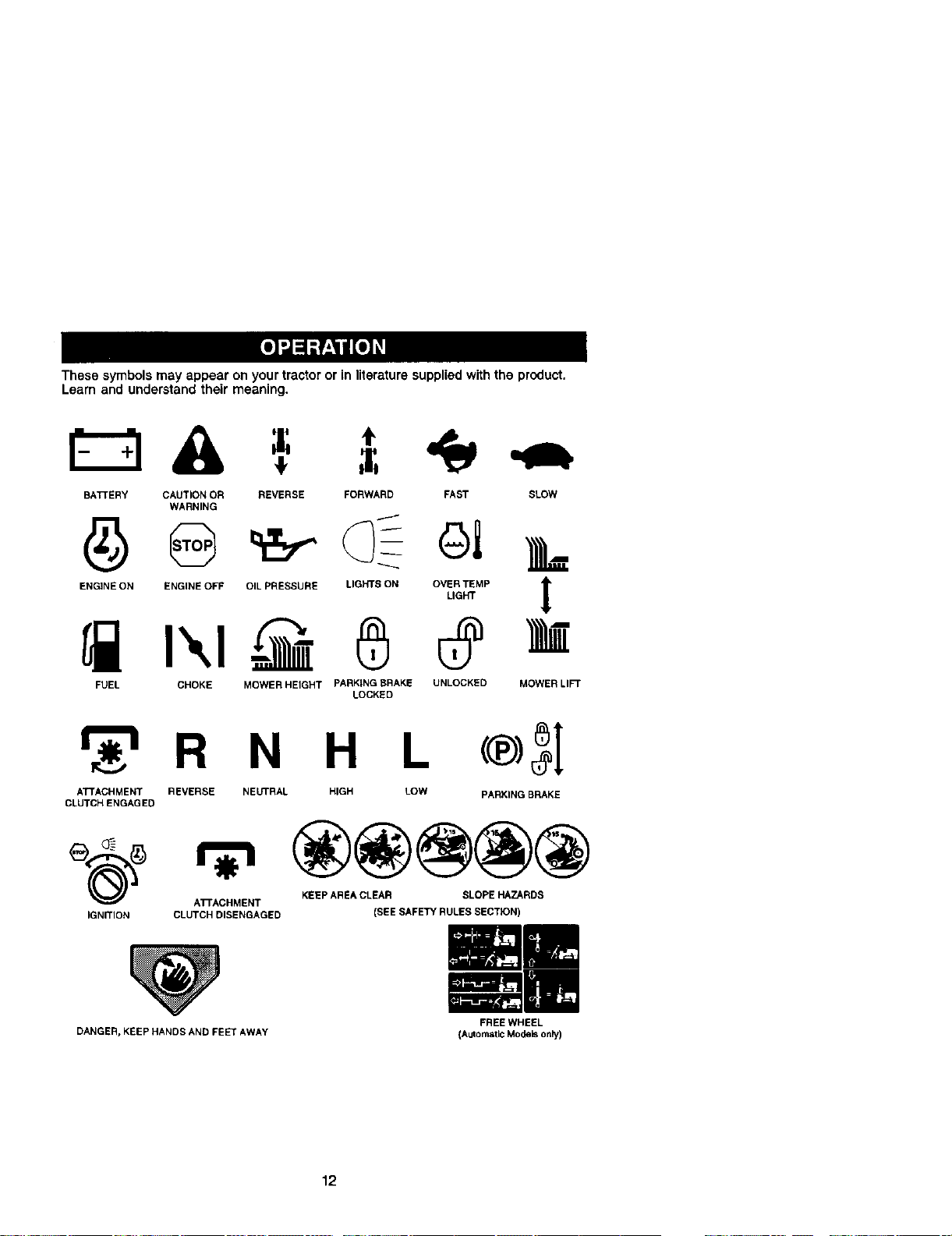
These symbols may appear on your tractor or in literature supplied withthe product.
Learn and understand their meaning.
BATTERY CAUTION OR REVERSE FORWARD FAST SLOW
WARNING
ENGINE ON ENGINE OFF OIL PRESSURE LIGHTS ON OVER TEMP
LIGHT
I',,I,@ 0
FUEL CHOKE MOWER HEIGHT PARKING BRAKE UNLOCKED
LOCKED
!
MOWERLI_
_r_RN H L
ATTACHMENT REVERSE NEUTRAL HIGH LOW
CLUTCHENGAGED
®3[
PARKING BRAKE
ATTACHMENT KEEP AREA CLEAR SLOPE HAZARDS
IGNITION CLUTCH DISENGAGED (SEE SAFETY RULES SECTION)
DANGER, KEEP HANDS AND FEEl"AWAY
FREE WHEEL
(Automatic Modelsonly)
12
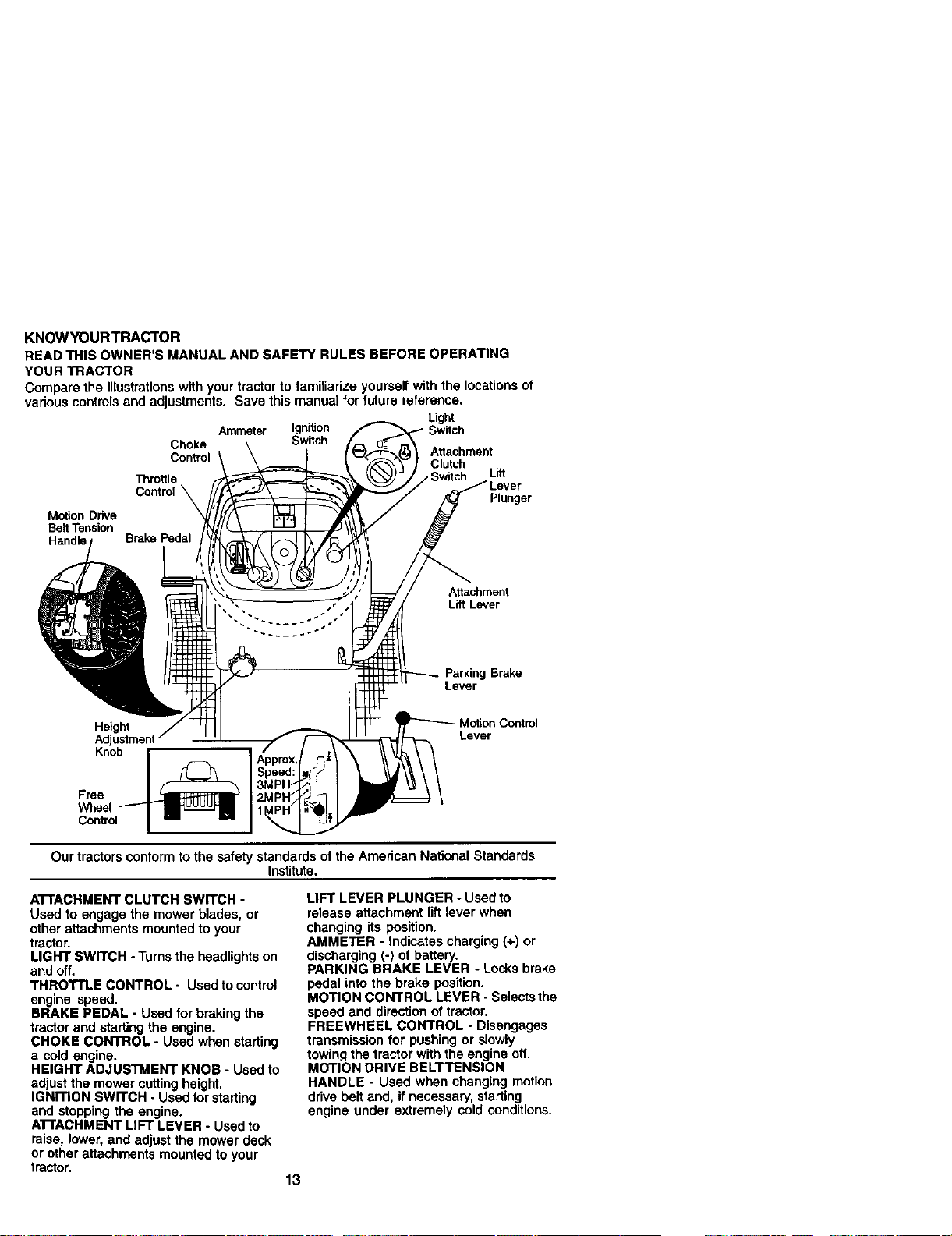
KNOWYOURTRACTOR
READ THIS OWNER'S MANUAL AND SAFETY RULES BEFORE OPERATING
YOUR TRACTOR
Compare the illustrationswith your tractorto famitiarize yourself with the locationsof
various controlsand adjustments. Save this manual for future reference.
Light
Ammeter Ignition witch
Choke Switch
Control Attachment
Clutch
Throttle Lift
Control_ Plunger
Motion Drive
Belt Tension
Attachment
Lift Lever
Parking Brake
Lever
Height _ontml
Adjustment Lever
Knob
Free
Wheel
Control
Our tractors conformto the safety standards of the American National Standards
Institute.
ATTACHMENT CLUTCH SWITCH -
Used to engage the mower blades, or
other attachments mounted to your
tractor.
LIGHT SWITCH - Turns the headlightson
and off.
THROTTLE CONTROL- Usedto control
engine speed.
BRAKE PEDAL - Used for brakingthe
tractor and starting the engine.
CHOKE CONTROL - Used when starting
a cold engine.
HEIGHT ADJUSTMENT KNOB - Used to
adjust the mower cutting height.
IGNITION SWITCH - Used for starling
and stopping the engine.
ATTACHMENT LIFT LEVER - Used to
raise, lower, and adjust the mower deck
or other attachments mounted to your
tractor.
13
LIFT LEVER PLUNGER - Used to
release attachment liftlever when
changing its position.
AMMETER - indicates charging (+) or
discharging (-) of battery.
PARKING BRAKE LEVER - Locks brake
pedal into the brake position.
MOTION CONTROL LEVER - Selectsthe
speed and directionof tractor.
FREEWHEEL CONTROL - Disengages
transmission for pushing or slowly
towing the tractor with the engine off.
MOTION DRIVE BELTTENSION
HANDLE - Used when changing motion
ddve belt and, if necessary, starting
engine under extremely cold conditions.
Theoperationofanytractorcanresultinforeignobjectsthrowninto I
the eyes, which can result in severe eye damage. Always wear safety
glasses or eye shields while operating your tractor or performing any I
adjustments or repairs. We recommend a wide vision safety mask over
spectac es or standard safety gasses.
HOWTO USEYOURTRACTOR
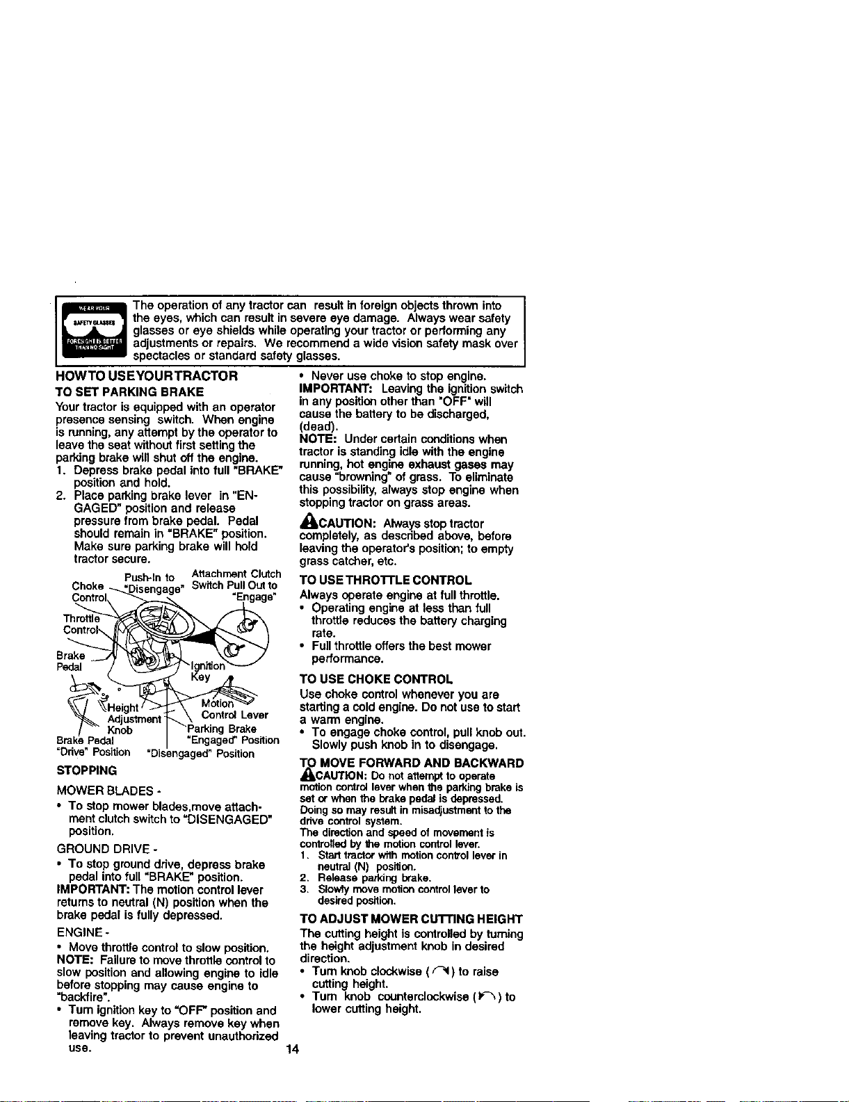
TO SET PARKING BRAKE
Your tractor is equipped with an operator
presence sensing switch. When engine
is running, any attempt by the operator to
leave the seat without first setting the
parking brake will shut off the engine.
1. Depress brake pedal into full "BRAKE"
position and hold.
2. Place parking brake lever in "EN-
GAGED" position and release
pressure from brake pedal. Pedal
should remain in =BRAKE" position.
Make sure parking brake will hold
tractor secure.
Push-Into AttachmentClutch
Choke -_._=Disengaga"SwilchPullOutto
Throttle
Brake _ _:_'_: L _(_-_ 2
Pedal / _'_/_ "_lglT_on"_--'_
: ControlLever
Adjustment \ ControlLev
/ "_" Knob _'Parking Brake
Brake Pedal "Engaged_Position
"Ddve"Position "Disengaged"Position
STOPPING
MOWER BLADES -
• To stop mower blades,move attach-
ment clutchswitch to=DISENGAGED"
position,
GROUND DRIVE -
• To stop groundddve, depress brake
pedal into full "BRAKE" position.
IMPORTANT: The motioncontrol lever
returnsto neutral (N) position when the
brake pedal is fully depressed.
ENGINE.
• Move throttlecontrol to slow position.
NOTE: Failure to movethrottle controlto
slow position and allowing engine to idle
before stoppingmay cause engine to
=backfire".
• Turn ignitionkey to "OFF" position and
remove key. Always remove key when
leaving tractor to prevent unauthorized
USe.
• Never use choke to stop engine.
IMPORTANT: Leaving the ignitionswitch
in any position other than "OFF" will
cause the battery to be discharged,
(dead).
NOTE: Under certain conditionswhen
tractor is standing idle with the engine
running, hot engine exhaust gases may
cause "browning"of grass. To eliminate
this possibility,always stop engine when
stoppingtractor on grass areas.
_CAUTION: Alwaysstop tractor
completely, as described above, before
leaving the operator's position;to empty
grass catcher,etc.
TO USE THRO'rrLE CONTROL
Always operate engine at full throttle.
• Operating engine at less than full
throttle reducesthe battery charging
rate.
• Full throttle offersthe best mower
performance.
TO USE CHOKE CONTROL
Use choke control whenever you are
starting a cold engine. Do not use to start
a warm engine.
• To engage choke control, pull knob out.
Slowly push knob in to disengage,
_l_ MOVE FORWARD AND BACKWARD
CAUTION: Do not attempt to operate
motion control lever when the parking brake is
set or when the brake pedal is depressed.
Doing so may result in misa_ustment to the
drive control system.
The direction and speed of movement is
controtled by the motion control lever.
t. Start tractor wffh motion control lever in
neutral (N) position.
2. Release parking brake.
3. Slowly move motion control lever to
desired position.
TO ADJUST MOWER cu'rnNG HEIGHT
The cutting height is controlled by turning
the height adjustment knob in desired
direction.
•Tum knob clockwise ( _ ) to raise
cutting height.
• Turn knob counterclockwise (_-_) to
lower cutting height.
14
The cuttingheight range is approximately
1-1/2" to 4-1/2". The heights are mea-
sured from the groundto the blade tip
with the engine not running. These
heights are approximate and may vary
depending upon soil conditions, height of
grass and types of grass being mowed.
• The average lawn should be cut to
approximately 2-1/2 inches during the
cool season and to over 3 inches
during hotmonths. For healthier and
better looking lawns, mow often and
after moderate growth.
• For best cuttingperformance, grass
over 6 inches in height should be
mowed twice. Make the first cut
relatively high;the second to desired
height.
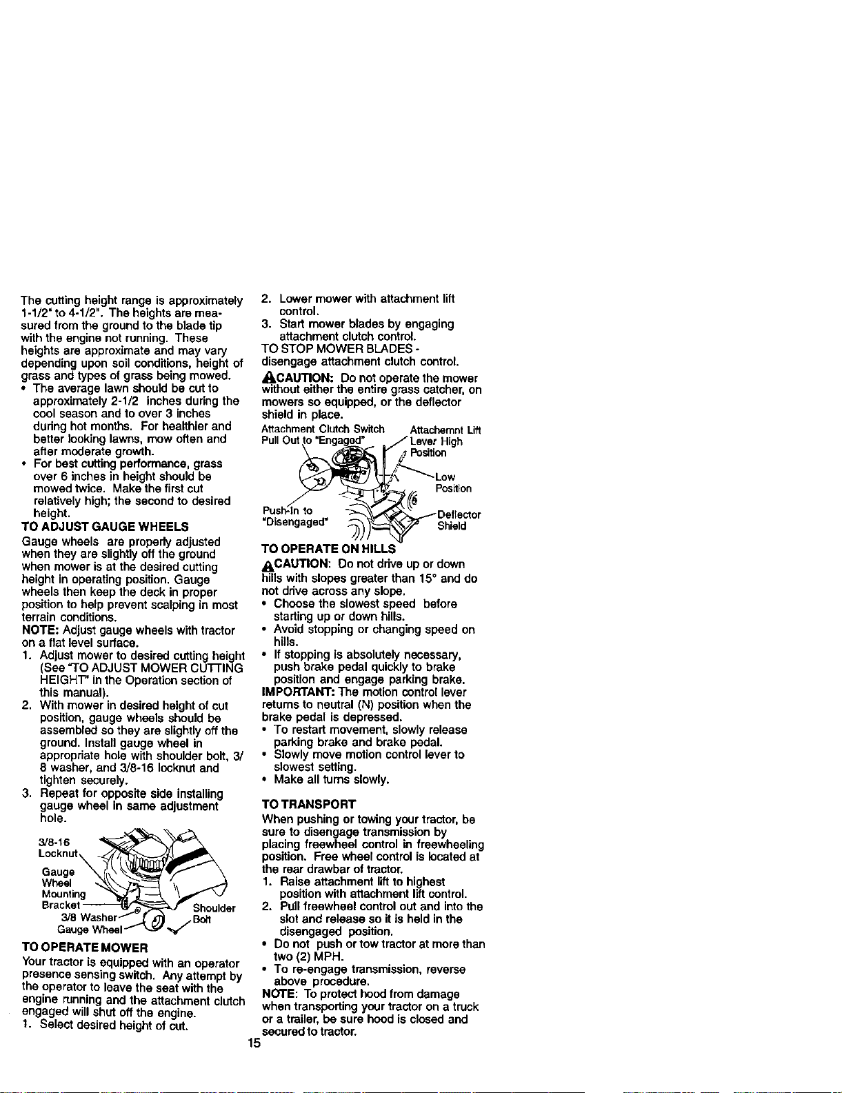
TO ADJUST GAUGE WHEELS
Gauge wheels are properly adjusted
when they are slightlyoff the ground
when mower is at the desired cutting
height in operating position. Gauge
wheels then keep the deck in proper
position to help prevent scalping in most
terrain conditions.
NOTE: Adjust gauge wheels with tractor
on a flat level surface.
1. Adjust mower to desired cuttingheight
(See "TO ADJUST MOWER CuT"rING
HEIGHT" inthe Operation section of
this manual).
2. With mower in desired height of cut
position, gauge wheels should be
assembled so they are slightlyoff the
ground. Install gauge wheel in
appropriate hole with shoulder bolt, 3/
8 washer, and 3/8-16 Iocknutand
tighten securely.
3. Repeat for opposite side installing
gauge wheel in same adjustment
hole.
3/8-16
Locknut
Gauge
Wheel
Mounting
Shoulder
Gaug. _f/Bolt
TO OPERATE MOWER
Yourtractor is equipped with an operator
presence sensing switch. Any attempt by
the operator to leave the seat with the
engine running and the attachment clutch
engaged will shut off the engine.
1. Select desired height of cut.
2. Lowermower with attachment lift
control.
3. Start mower blades by engaging
attachment clutchcontrol.
TO STOP MOWER BLADES -
disengage attachment clutch control
_CAUTION: Do not operate the mower
withouteither the entire grass catcher,on
mowers so equipped, or the deflector
shield in place.
AtlachmentClutchSwitch AttachemntLift
PullOut High
,_Position
Position
Push-l_nto
"Disengaged" _) Shield
TO OPERATE ON HILLS
ACAUTION: Do not drive up or down
hills with slopes greater than 15° and do
not drive across any slope.
• Choose the slowest speed before
starting up or down hills.
• Avoid stopping or changing speed on
hills.
• If stopping is absolutely necessary,
push brake pedal quicklyto brake
position and engage parking brake.
IMPORTANT: The motioncontrol lever
retums to neutral (N) position when the
brake pedal is depressed.
• To restart movement, slowly release
parking brake and brake pedal.
• Slowly move motion control lever to
slowest setting.
• Make all turns slowly.
TO TRANSPORT
When pushing or towingyour tractor,be
sure to disengage transmission by
placing freewheel control in freewheeling
position. Free wheel control is located at
the rear drawbar of tractor.
1. Raise attachment liftto highest
positionwith atlachment liftcontrol.
2. Pullfreewheel controlout and intothe
slotand release so it is held in the
disengaged position.
• Do not push or tow tractor at more than
two (2) MPH.
• To re-engage transmission, reverse
above procedure.
NOTE: To protect hoodfrom damage
when transporting your tractor on a truck
or a trailer, be sure hood is closed and
securedto tractor.
15
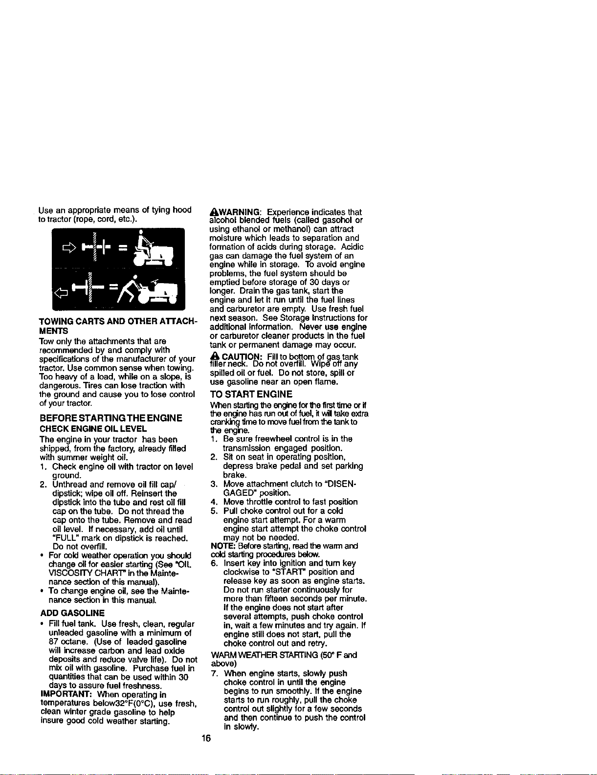
Use an appropriate means of tying hood
to tractor (rope, cord,etc.).
TOWING CARTS AND OTHER ATrACH-
MENTS
Tow onlythe attachments that are
recommended by and comply with
specificationsofthe manufacturer of your
tractor. Use common sense when towing.
Too heavy ofa load, while on a slope, is
dangerous.Tires can lose traction with
the ground and cause you to lose control
ofyour tractor.
BEFORE STARTINGTHE ENGINE
CHECK ENGINE OIL LEVEL
The engine in your tractor has been
shipped, from the factory, already filled
with summer weight oil
t. Check engine oilwith tractor on level
ground.
2. Unthread and remove oil fill cap/
dipstick;wipe oil off. Reinsert the
dipstickinto the tube and restoil fill
cap on the tube. Do not thread the
cap onto the tube. Remove and read
oil level. If necessary, add oil until
=FULL" mark on dipstick is reached.
Do notoverfill.
• For coldweather operation you should
change oilforeasier starting (Sea "OIL
VISCOSITY CHART" inthe Mainte-
nance sectionof this manual).
• To change engine oil,see the Mainte-
nance section in this manual,
ADD GASOLINE
• Fillfuel tank. Use fresh, clean, regular
unleaded gasoline with a minimum of
87 octane. (Use of leaded gasoline
will increase carbon and lead oxide
depositsand reduce valve life). Do not
mix oil with gasoline. Purchase fuel in
quantitiesthat can be used within 30
days to assure fuel freshness.
IMPORTANT: When operating in
temperatures beiow32°F(0°C), use fresh,
clean winter grade gasoline to help
insure good cold weather starting.
4_WARNING: Experience indicates that
alcohol blended fuels (called gasohol or
using ethanol or methanol) can attract
moisture which leads to separation and
formation ofacids during storage. Acidic
gas can damage the fuel system of an
engine while in storage. To avoid engine
problems, the fuel system should be
emptied before storage of 30 days or
longer. Drain the gas tank, start the
engine and let it run until the fuel lines
and carburetor are empty. Use freshfuel
next season. See Storage Instructionsfor
additional Information. Never use engine
or carburetor cleaner products in the fuel
tank or permanent damage may occur.
A CAUTION: Fillto bottom of gastank
fillerneck. Do not overfill. Wipe oft any
spilled oil or fuel. Do not store, spillor
use gasoline near an open flame.
TO START ENGINE
When staringthe engineforthefirsttimeorif
the engine has runout offuel,itwil takeextra
crankit_'_metomovefuelfromthe tankto
theengine.
t. Be sure freewheel control is in the
transmission engaged position.
2. Sit on seat in operating position,
depress brake pedal and set parking
brake.
3. Move attachment clutch to"DISEN-
GAGED" position.
4. Move throttlecontrolto fast position
5. Pull choke controlout for a cold
engine start attempt. For a warm
engine start attempt the choke control
may not be needed.
NOTE: Beforestarting,readthe warmand
coldstaringproceduresbelow.
6. Insert key intoignitionand turn key
clockwise to "START" position and
release key as soon as engine starts.
Do not run starter continuouslyfor
more than fifteen secondsper minute.
If the engine does not start after
several attempts, push choke control
in, wait a few minutes and try again. If
engine still does notstart, pullthe
choke control out and retry.
WARMWEATHER STARTING(50° F and
above)
7. When engine starts, slowly push
choke control in until the engine
begins to run smoothly. If the engine
starts to run roughly,pullthe choke
control out slightlyfor a few seconds
and then continueto push the control
in slowty.
16
• The attachmentsand grounddrive can
nowbe used.if the engins doe6notaccept
the load,restarttheengk_eand allowitto
warmupfor one minuteusingthe choke
as described above.
COLD WEATHER STARTING(50° Fand
below)
7. When engine starts, slowly push
choke control in until the engine
begins to run smoothly. Continue to
push the choke control in small steps
allowing the engine to accept small
changes in speed and load, until the
choke control isfully in. If the engine
startsto run roughly,pull the choke
controlout slightlyfor a few seconds
and then continue to push the control
in slowly. This may require an engine
warm-up period from several seconds
to several minutes, depending on the
temperature.
NOTE: In extreme coldconditions,if
engine will not start you may need to
disengage the motion drive belt as
follows:
1. Be sure parking brake is engaged.
2. Remove retainer spring from the drive
belt tension handle to relieve belt
tension.
3. Start engine and allow Rto warm up
forthree (3) minutes.
4. Shut-oft engine and engage perking
brake.
5. Engage drive belt tension handle and
replace the retainer spring.
AUTOMATICTRANSMISSION WARMUP
Before drivingthe unitin cold weather,
the transmission should be warmed up as
follows:
1. Be sure the tractor is on level ground.
2. Place the motioncontrol lever in
neutral. Release the parking brake
and let the brake slowly return to
operating position.
3. Allow one minute for transmissionto
warm up. This can be done dudng the
engine warm up period.
• The attachments can be used dudng
the engine warm-up pedod after the
transmission has been warmed up and
may require the choke control be
pulled out slightly.
NOTE: If at a high altitude (above 3000
feet) or in coldtemperatures (below 32 F)
the carburetor fuel mixture may need to
be adjusted for best engine performance.
See "TO ADJUST CARBURETOR" in the
Service and Adjustments section of this
manual.
PURGETRANSMISSION
_ILCAUTION: Never engage or disengage
freewheel lever while the engine is running.
To ensure proper operationand perfor-
manse, it is recommendedthatthe trans-
missionbe purged before operatingtractor
for the first time.This procedurewill remove
any trapped air insidethe transmission
which may have developed dudngship-
pingof yourtractor.
IMPORTANT: Should yourtransmission
require removalfor service or replacement,
it should be purged after reinstallation
before operatingthe tractor.
1. Place tractor safely on level surface
with engine off and parking brake set.
2. Disengage transmission by placing
freewheel control in freewheeling
position (See "TO TRANSPORT" in this
section of manual).
3. Sitting in the tractor seat, start engine.
After the engine is running, move
throttle control to slow position.
Disengage parking brake.
4. Move motion control lever to full
forward position and hold for five (5)
seconds. Move lever to full reverse
position and hold for five (5) seconds.
Repeat this procedure three (3) times.
NOTE: Dudng this procedure there willbe
no movement of drive wheels. The air is
being removed from hydraulic ddve system.
5. Move motion control lever to neutral
(N) position. Shut- off engine and set
parking brake.
6. Engage transmission by placing
freewheel control in driving position
(See "TO TRANSPORT" in this section
of manual).
7. Sitting in the tractor seat, start engine.
After the engine is running, move
throttle control to half (1/2) speed.
Disengage parking brake.
8. Slowly move motion control lever
forward, after the tractor moves
approximately five (5) feet, slowly
move motion controllever to reverse
position. After the tractor moves
approximately five (5) feet return the
motion control lever to the neutral (N)
position. Repeat this procedure with
the motion control lever three (3) times.
Your tractor is now purged and now ready
for normal operation.
17
MOWINGTIPS
• Tire chains cannot be used when the
mower housing is attached to tractor,
• Mower should be properly leveled for
best mowing performance. See "TO
LEVEL MOWER HOUSING" in the
Service and Adjustments section of this
manual.
• The left hand side of mower should be
used for trimming.
• Ddve so that clippings are discharged
ontothe area that has been cut. Have
the cutarea to the rightof the tractor.
This will result in a more even distribu-
tion of clippings and more uniform
cutting.
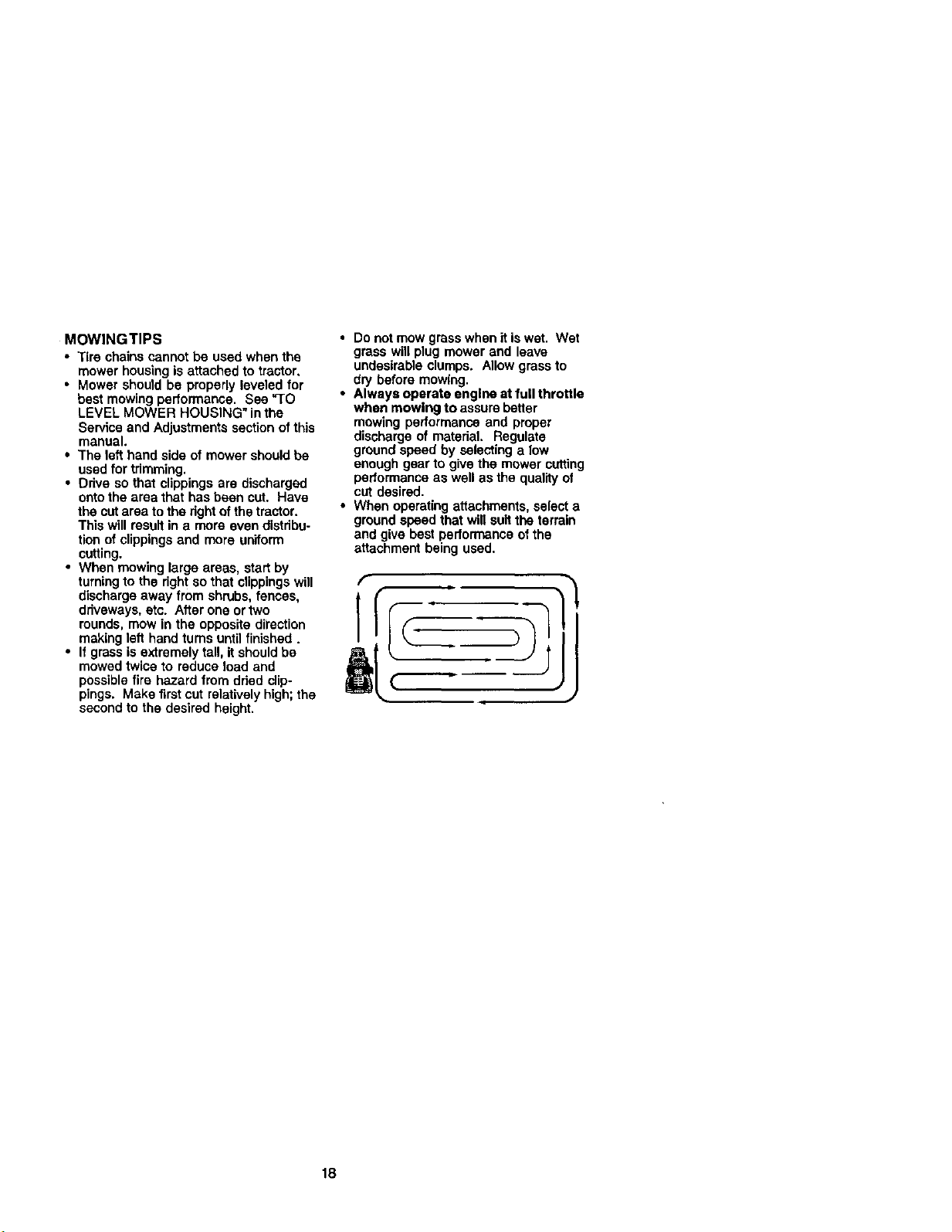
• When mowing large areas, start by
turningto the rightso that clippingswill
discharge away from shrubs, fences,
driveways, etc. After one ortwo
rounds, mow in the opposite direction
making lef_hand turns until finished.
• If grass is extremely tall, it should be
mowed twice to reduce load and
possiblefire hazard from dded clip-
pings. Make first cut relatively high;the
second to the desired height.
• Do notmow grass when itis wet. Wet
grass will plug mower and leave
undesirable clumps. Allow grass to
dry before mowing.
• Always operate engine at full throttle
when mowing to assure better
mowing performance and proper
discharge of material. Regulate
ground speed by selecting a low
enough gear to give the mower cutting
performance as well as the qualityof
cut desired.
• When operating aftechments, select a
groundspeed that will suit the terrain
and give best performance of the
attachment being used.
[
r
18
sc.ooo.o
c_k_ Prim.r, V' I/
CheCk Operator P_mce and
L®r_. c,,. V' I/
R cle=sa_,y=_aro_ J b,/
Check Tmr_axle Cooling I_
Adju=B_* _(s) T_n¢o. I/s
AdlL_ N D_VeBeltls) T_'_ k_ fl_s
i Oe_n AirFita_ I_#=
Cle_'_Air Screen _;
_0e_ Muffk_r/Sp_rkA_t_ b/
_ce C_lN._r (l_equipped) I_
N Clean Engine CoOlingFins _
ReplaceAir RR_ pape_ Cartridge 1_2
3. N _;€,p_ w_,_oz rl_r ohat_ OZw:_,y EObe_,_, 7. _ _nt _ p_t _dt I_ _ t.4ol, m_dtrz_m,
GENERAL RECOMMENDATIONS
The warrantyon thistractordoes notcover
items that have been subjectedto operator
abuse or negliganoe. To receive full value
fromthe warranty,operator must maintain
tractoras instructedin this manual
Some adjustments willneed to be made
pededicaltyto properlymaintain your
tractor.
All adjustmentsin the Serviceand
Adjustments section ofthis manual should
be checkedat least once each season.
• Once a year you should replacethe
spark plug,clean or replace air filter,and
check blades and beltsfor wear. A new
spark plug and clean air filterassure
proper air-fuel mixtureand help your
engine runbetter and last longer.
BEFORE EACH USE
1, Check engine oil level.
2. Check brake operation.
3. Check tire pressure.
4. Check operator presence and
interlock systems for proper operation.
5. Check for loose fasteners,
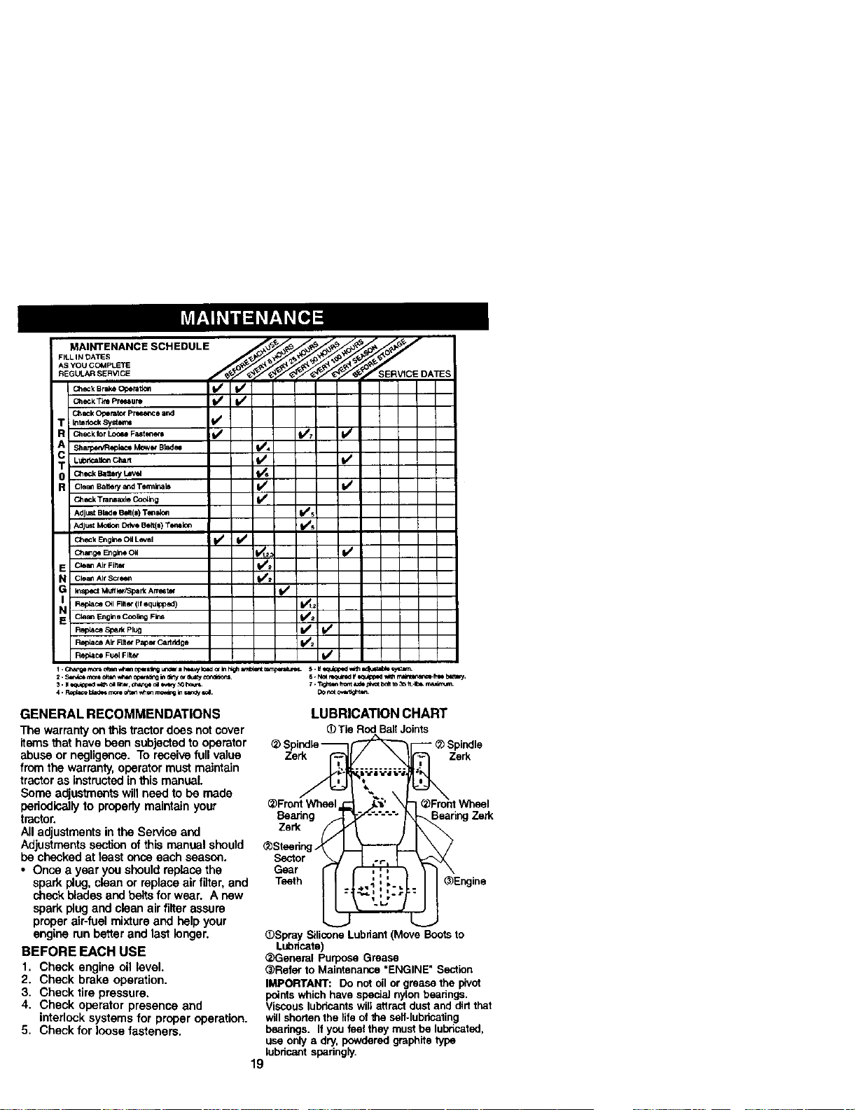
LUBRICATION CHART
(_Tia RodBallJoints
(_ SzPel_ndle---'_ I _ Zerk
,k
_Front Wheel _'_' \
Baanng --_'_-'-'-'-" BearingZerk
Zerk _
@Steering_'_
Sector _ _ .,...
Gear I
Teeth ._._ ; ..,.
(])SpraySiliconeLubriant (MoveBootsto
Lubricate)
<___eneralPurposeGrease
(_Referto Maintenance"ENGINE"Section
IMPORTANT: Donotoilor greasethe pivot
pointswhichhavespeciaJnylonbe_dngs.
Viscouslubricantswiltsttract dustand dirtthat
willshortenthe lifeofthe self-lubricating
bearings.Ifyou feeltheymustbelubricated,
useonlya dry,powderedgraphitetype
lubricant sparingly.
19
TRACTOR
Always observe safety mias when perform-
ing any maintenance.
BRAKE OPERATION
Iftractor requiresmorethen six (6) feet
stoppingdistance at high speed in highest
gear,then brakemustbe adjusted.
(Contact a Sears or other qualifiedservice
center).
TIRES
• Maintainproper air pressure in all tires
(See "PRODUCT SPECIFICATIONS"
section of this manual).
• Keeptiresfree of gasoline, og,or insect
controlchemicalswhich can harm
robber.
• Avoid stumps, stones, deep ruts,sharp
objects and other hazards that may
cause tire damage.
NOTE: To seal tire punctures and prevent
flat tires due to slow leaks, fire sealant may
be purchased from your local parts dealer.
Tire sealant also prevents tire dry rot and
corrosion.
OPERATOR PRESENCE SYSTEM
Be sure operator presence and interlock
systems are working properly. If your
tractor doesnot function as described,
repair the problem immediately.
• The engine shouldnot start unlessthe
brake pedal is fully depressed and
attachment clutchcontrolis inthe
disengaged position,
• "Whenthe engine is running,any attempt
by the operatorto leave the seat without
firstsettingthe parkingbrake should shut
off the engine.
• When the engine is runningand the
attachment clutchis engaged, any
attempt bythe operator to leave the seat
shouldshut offthe engine.
• The attachment dutch shouldnever
operate unlessthe operator is inthe
seat.
BLADE CARE
For bestresultsmower blades must he
keptsharp. Replace bent or damaged
blades.
BLADE REMOVAL
1. Raise mower to highestpositionto
allow access to blades.
2. Remove hox bolt, lock washer and fiat
washer securing blade.
3. Install new or resharpened blade with
trailing edge up towards deck as
shown.
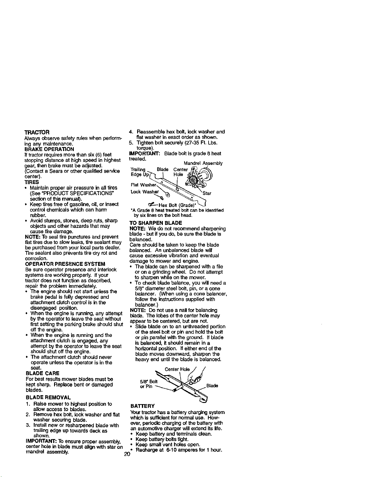
IMPORTANT: To ensure proper assembly,
center holein blade must align with staron
4. Reassemble hex bolt, lockwasher and
flat washer in exact order as shown.
5. Tighten boltsecurely(27-35 Ft. Lbs.
torque).
IMPORTANT: Bladeboltisgrade 8 heat
treated.
MandrelAssembly
Trailing. Blade Center
Hole
Fist
Lock
_P----HexBolt,
*A Grade8 heat treatedboltcanbeidentified
by sixlinesonthebolthead.
TO SHARPEN BLADE
NOTE: We do not recommend sharpening
blade - butif you do, be surethe blade is
balanced.
Care should be taken to keep the blade
balanced. An unbalanced biape wifl
cause excessivevibrationand eventual
damage to mower and engine.
• The blade can he sharpened with a file
or on a grindingwheel. Do not attempt
to sharpen while on the mower.
• To check blade balance, you will need a
5/8" diametersteel bolt, pin, or a cone
halancer. (When usinga cone belancer,
fellowthe instructionssupplied with
balancer.)
NOTE: Do notuse a nailforbalendng
blade. The lobesofthe center holemay
appear tobe centered, but are not.
• Slide blade on to an unthreaded portion
ofthe steel boltor pin and holdthe bolt
or pin parallel withthe ground. If blade
is balanced, it should remain in a
horizontalposition. Ifeither end of the
blade moves downward, sharpen the
heavy end untilthe blade is balanced.
5/8"Bo_
or Pin _Blade
BA't-FERY
Yourtractorhas a battery chargingsystem
which issufficientfor normaluse. How-
ever, periodic charging of the battery with
an automotivechargerWIllextend its life.
• Keep batteryand terminals dean.
: Keep batterybolts tight.
Keep small vent holesopen.
• Rechargeat 6-1Oamperasfor 1 hour.
mandrel assembly.
2O
NOTE: The originalequipmentbattery on
yourtractor ismaintenancefree. Do not
attemptto openor remove caps or covers.
Addingor checkinglevel of electrolyteis
not necessary.
TO CLEAN BATTERYAND TERMINALS
Corrosionand dirton the battery and
terminalscan cause the battery toleak"
power.
1. Remove terminal guard.
2. Disconnect BLACK batterycable first
then RED batterycable and remove
battery fromtractor.
3. Rinsethe battery with plainwater and
dry.
4. Clean terminals and battery cable ends
with wire brush untilbright.
5. Coat terminals with grease or petro-
leum jelly.
6. Reinstall battery (See "REPLACING
BATTERY" in the SERVICE AND
ADJUSTMENTS section of this
manual).
V-BELTS
Check V-beltsfor deteriorationand wear
after 100 hours of operationand replace if
necessary.The beltsare not adjustable.
Replace beltsif theybegin to slipfrom
wear.
TRANSAXLE COOLING
The transmissionfan and coolingfins
shouldbe kept cleanto assure proper
cooling.
Do not attemptto cleanfan ortransmission
while engine is runningor while the
transmissionis hot.To preventpossible
damage to seals, do not use high pressure
water or steam to blsan transaxle.
• Inspectcooling fan to he sure fan blades
ere intact and clean.
• Inspectcoolingfinsfor dirt,grass
clippingsand other materials. To
preventdamage to seals, de nat use
compresssd air or high pressuresprayer
to clean coolingfins.
TRANSAXLE PUMP FLUID
The transaxle was sealed at the factory
and fluidmaintenance is not required for
the lifeof the transaxle. Shouldthe
transaxle ever leak or requireservicing,
contactyour nearest authorizedservice
center/department.
ENGINE
LUBRICATION
Only use high qualitydetergent _ rated
with API serviceclassificationSF-SJ.
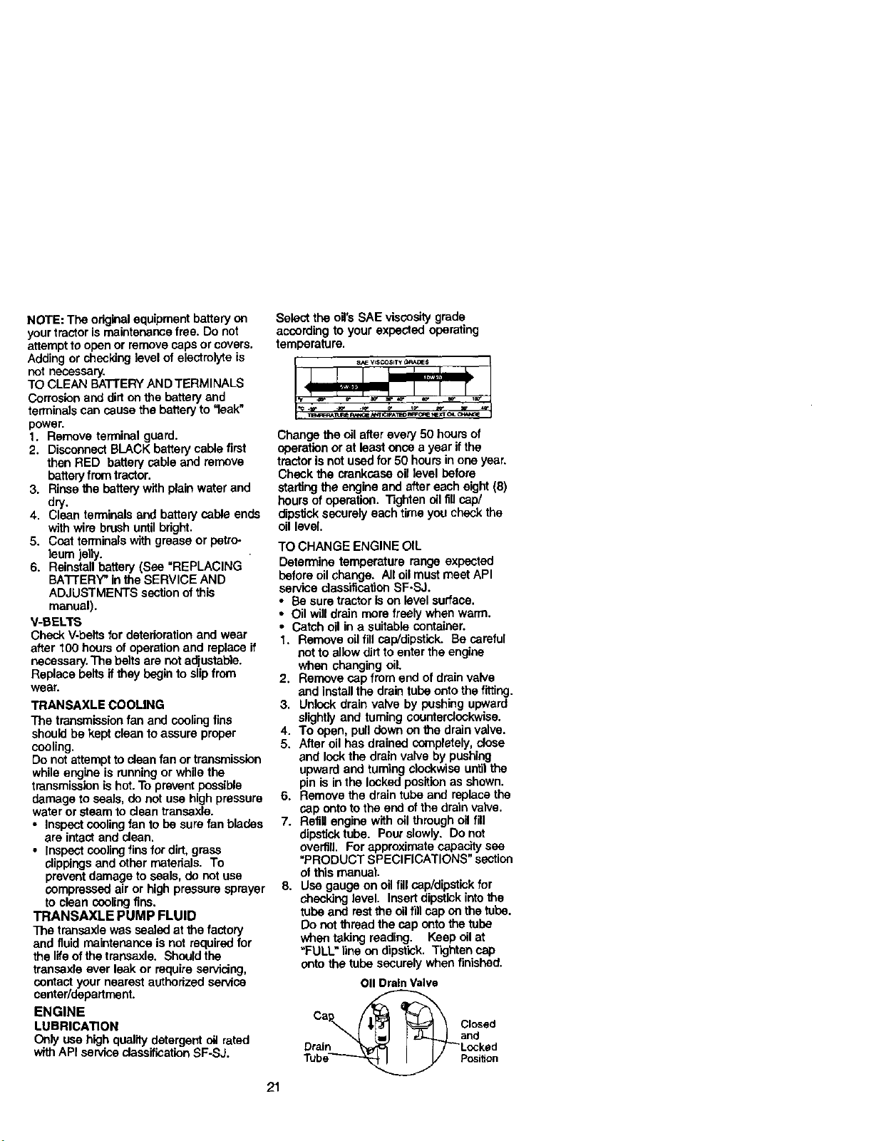
Select the oil'sSAE viscositygrade
according to your expected operating
temperature.
21
Change the oil after every 50 hours of
operationor at least once a year ifthe
tractor isnot usedfor50 hours inone year.
Check the crankcase oil level before
starting the engineand after each eight(8)
hoursof operation. Tighten oilflil cap/
dipsticksecurely each time you checkthe
oil level.
TO CHANGE ENGINE OIL
Determine temperature range expected
before oilchange. All oil must meet API
service classificationSF-SJ.
• Be sure tractor is on level surface.
• Oil will drain more freely when warm.
• Catch oil in a suitable container.
1. Remove oil fill cep/dipstick. Be careful
notto allowdirt to enter the engine
when changing oil.
2. Remove cap from end of drain valve
and install the drain tuba onto the fitting.
3. Unicck drain valve by pushing upward
slightly and taming counterclockwise.
4. To open, pull down on the drainvalve.
5. After oil has drained completely, close
and look the drain valve by pushing
upwardand taming clockwise untilthe
pin is inthe lockedpositionas shown.
6. Remove the draintube and replacethe
cap onto tothe end of the drainvalve.
7. Refillengine with oil through oilfill
dipsticktube. Pour slowly. Do not
overfill. For approximatecapacitysee
"PRODUCT SPECIFICATIONS" section
of this manual.
8. Usa gauge on oilfill cep/dipstick for
checkinglevel. Insert dipstick into the
tube and rest the oil fill cap onthe tube.
Do not thread the cap onto the tube
when taking reading. Keep oil at
"FULL" line on dipstick. Tighten cap
onto the tube securely when finished.
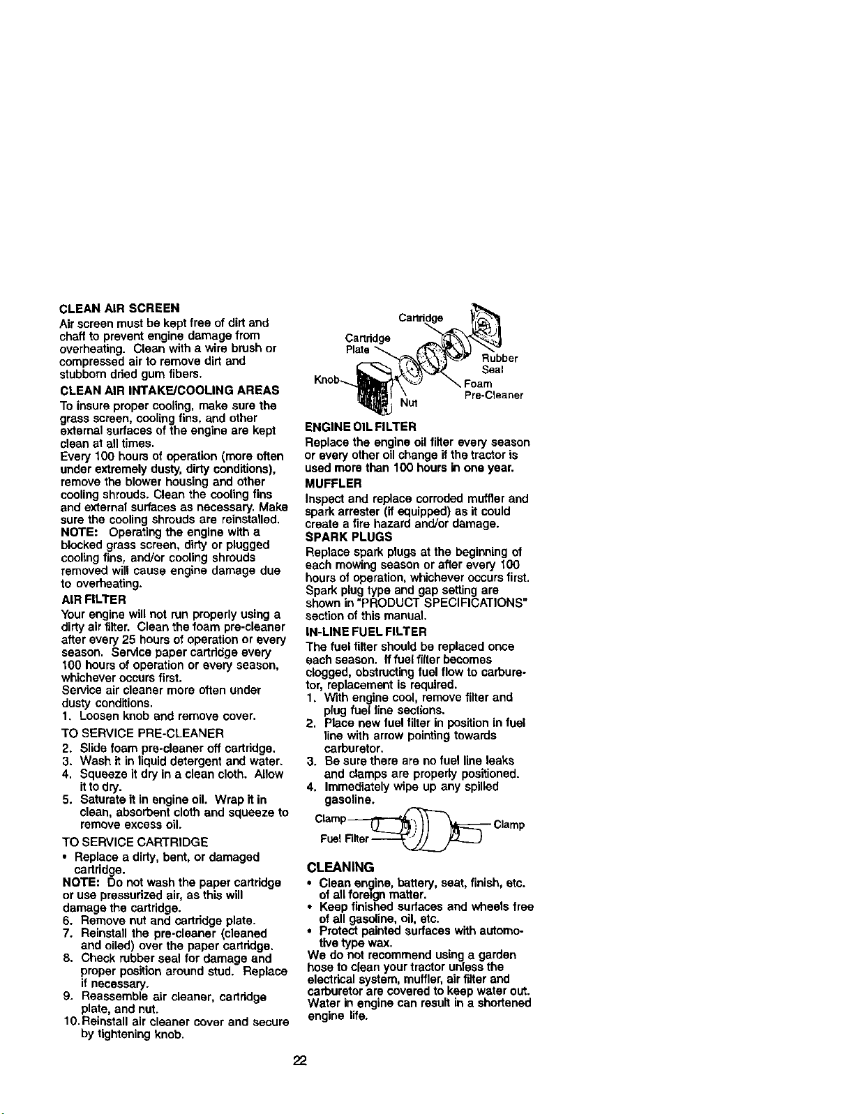
011DrainValve
Cap_ _ Closed
or.,. 1 t-TLt .e.
Tube_ Position
CLEANAIRSCREEN
Airscreenmustbekeptfreeofdirtand
chafftopreventengine damage from
overheating. Clean with a wire brush or
compressed air to remove dirt and
stubborndded gum fibers.
CLEAN AIR INTAKE/COOLING AREAS
To insure proper cooling, make sure the
grass screen, coolingfins, and other
external surfaces of the engine are kept
clean at all times.
Every 100 hours of operation (more often
under extremely dusty,dirty conditions),
remove the blower housing and other
coolingshrouds. Clean the cooling fins
and external surfaces as necessary. Make
sure the coolingshrouds are reinstalled.
NOTE: Operating the engine with a
blocked grass screen, dirty or plugged
coolingfins, and/or cooling shrouds
removed will cause engine damage due
to overheating.
AIR FILTER
Your engine will not run properly using a
dirty airfilter. Clean the foam pre-cleaner
after every 25 hours of operation or every
season. Service paper cartridge every
t0O hours of operation or every season,
whichever occurs first.
Service air cleaner more often under
dusty conditions.
1. Loosen knob and remove cover.
TO SERVICE PRE-CLEANER
2. Slide foam pre-claaner off carfddge.
3. Wash it in liquid detergent and water.
4. Squeeze it dry in a clean cloth. Allow
it to d_/.
5. Saturate it in engine oil, Wrap it in
clean, absorbent cloth and squeeze to
remove excess oil.
TO SERVICE CARTRIDGE
• Replace a dirty,bent, or damaged
cartridge.
NOTE: Do not wash the paper cartridge
or use pressurized air, as this will
damage the cartridge.
6. Remove nut and cartddge plate.
7. Reinstall the pre-cleaner (cleaned
and oiled) over the paper cartridge.
8. Check rubber seal for damage and
proper position around stud. Replace
if necessary.
9. Reassemble air cleaner, cartridge
plate, and nut.
10.Reinstall air cleaner cover and secure
by tightening knob.
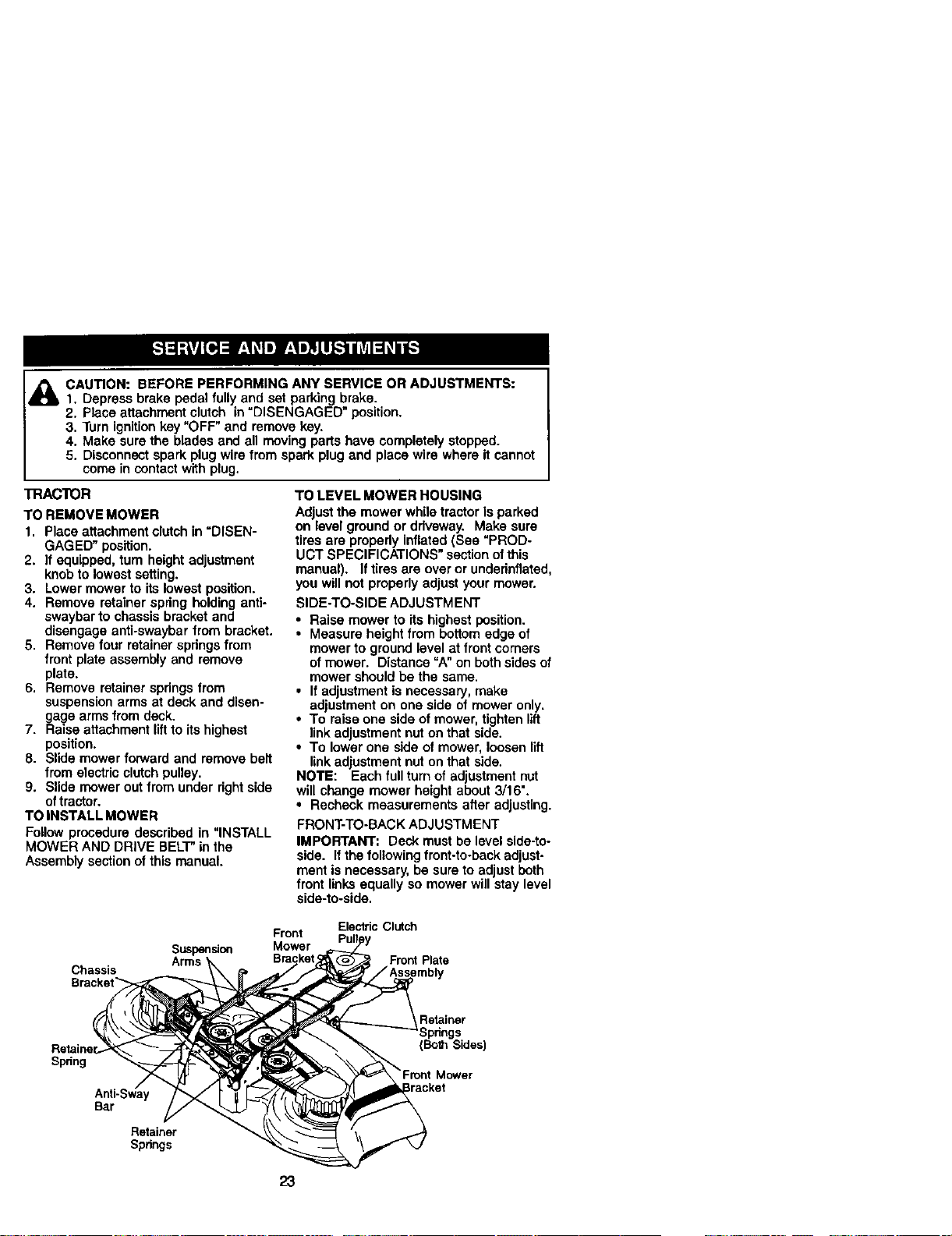
Cartddge
Plate
Knob_
Rubber
Seal
Foam
Pre-Cleaner
ENGINE OIL FILTER
Replace the engine oil filterevery season
or every other oil change ifthe tractor is
used more than 100 hours in one year.
MUFFLER
Inspect and replace corroded muffler and
spark arrester (it equipped) as it could
create a fire hazard and/or damage.
SPARK PLUGS
Replace spark plugs at the beginning of
each moWing season or after every fO0
hours of operation,whichever occursfirst.
Spark plug type and gap setting are
shown in =PRODUCT SPECIFICATIONS"
section of this manual.
IN-LINE FUEL FILTER
The fuel filter should be replaced once
each season, fffuel filter becomes
clogged, obstructingfuel flow to carbure-
tor, replacement is required.
1. With engine cool, remove filter and
plugfuel line sections.
2. Place new fuel filter in position in fuel
line with arrow pointingtowards
carburetor.
3. Be sure there are no fuel line leaks
and clamps are properly positioned.
4. Immediately wipe up any spilled
gasoline.
Clamp_ Clamp
FuelFiNer_
CLEANING
i Clean engine, battery, seat, finish, etc.
of all fore=gnmatter.
Keep finished surfaces and wheels free
of all gasoline, oil,etc.
• Protect painted surfaces with automo-
tive type wax.
We do not recommend using a garden
hose to clean your tractor unless the
electrical system, muffler, airfilter and
carburetor are covered to keep water out.
Water in engine can result in a shortened
engine life.
22
_ AUTION: BEFORE PERFORMING ANY SERVICE OR ADJUSTMENTS:
1. Depress brake pedal fully and set parking brake.
2. Place attachment clutch in DISENGAGED position.
3. Turn ignitionkey "OFF" and remove key.
4. Make sure the blades and all moving parts have completely stopped.
5. Disconnect spark plug wire from spark plug and place wire where it cannot
come in contact with plug.
TRACTOR
TO REMOVE MOWER
1. Place attachment clutch in =DISEN-
GAGED" position.
2. If equipped, turn heightadjustment
knob to lowest setting.
3. Lowermower to its lowest position.
4. Remove retainer spring holding anti-
swaybar to chassis bracket and
disengage anti-swaybar from bracket.
5. Remove four retainer spdngs from
front plate assembly and remove
plate.
6. Remove retainer spdngs from
suspensionarms at deck and disen-
gage arms from deck.
7. Raise attachment lift to its highest
position.
8. Slide mower forward and remove belt
from electric clutch pulley.
9. Slide mower out from under dght side
oftractor,
TO INSTALL MOWER
Follow procedure described in =INSTALL
MOWER AND DRIVE BELT"in the
Assembly section of this manual.
TO LEVEL MOWER HOUSING
Adjust the mower while tractor is parked
on level ground or driveway. Make sure
tires are pmpedy inflated (See "PROD-
UCT SPECIFICATIONS" section ofthis
manual). Iftires are over or undsdnflated,
you will not properly adjust your mower.
SIDE-TO-SIDE ADJUSTMENT
• Raise mower to its highest position.
• Measure height from bottom edge of
mower to ground level at front comers
of mower. Distance =A"on both sides of
mower should be the same.
• If adjustment is necessary, make
adjustment on one side of mower only.
• To raiseone side of mower, tighten lift
link adjustment nut on that side.
• To lower one side of mower, loosen lift
linkadjustment nut on that side.
NOTE: Each full turn of adjustment nut
will change mower height about 3/16".
• Recheck measurements after adjusting.
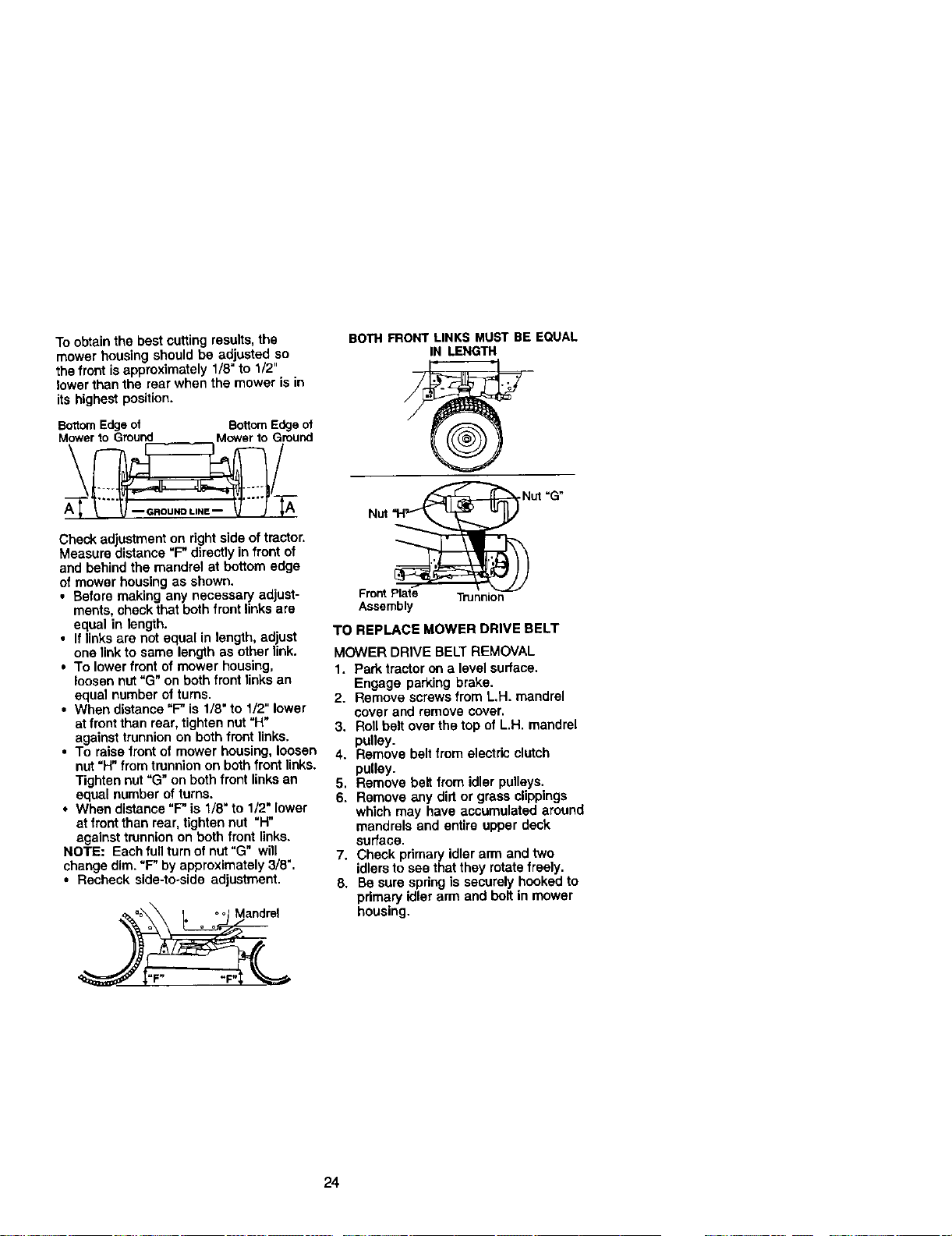
FRONT-TO-BACK ADJUSTMENT
IMPORTANT: Deck must be level side-to-
side. If the followingfront-to-beck adjust-
ment is necessary, be sure to adjust both
front links equally so mower will stay level
side-to-side.
Chassis
Suspension
Arms
Electric Clutch
Fronl
Mower
Bracket Front Plate
3mbly
Spnng
Bar
Retainer
Spnngs
Re_iner
Spnngs
(Bo_ Sides)
" Front Mower
23
To obtain the best cuttingresults,the
mower housing should be adjusted so
the frontis approximately 1/8=to 1/2"
lower than the rear when the mower is in
its highestposition.
BottomEdgeof BottomEdgeot
Check adjustment on right side of tractor.
Measure distance "F" directlyin front of
and behind the mandrel at bottom edge
of mower housing as shown.
• Before making any necessary adjust-
ments, checkthat both front links are
equal in length.
• If linksare not equal in length, adjust
one link to same length as other link.
• To lower front of mower housing,
loosen nut "G" on both front links an
equal number of turns.
• When distance "F" is 1/8" to 1/2" lower
at front than rear, tighten nut "H"
against trunnion on both front links.
• To raise front of mower housing, loosen
nut "H" from trunnion on both front links.
Tighten nut "G" on both front links an
equal number of turns.
• When distance "F" is 1/8" to 1/2" lower
at front than rear, tighten nut "H"
against trunnion on both front links.
NOTE: Each full turn of nut"G" will
change dim. "F" by approximately 3/8".
• Recheck side-to-side adjustment.
BOTH FRONTLINKS MUST BE EQUAL
IN LENGTH
Nut "G"
Nut
Front Plate Trunnion
Assembly
TO REPLACE MOWER DRIVE BELT
MOWER DRIVE BELT REMOVAL
1. Park tractor on a level surface.
Engage parking brake.
2. Remove screws from L.H. mandrel
cover and remove cover,
3. Roll belt over the top of L.H. mandrel
pulley.
4. Remove belt from electric clutch
pulley.
5. Remove belt from idler pulleys.
6. Remove any dirt or grass clippings
which may have accumulated around
mandrels and entire uPper deck
surface.
7. Check pdmary idler arm and two
idlers to see that they rotate freely.
8. Be sure spring is securely hooked to
primary idler arm and bolt in mower
housing.
24
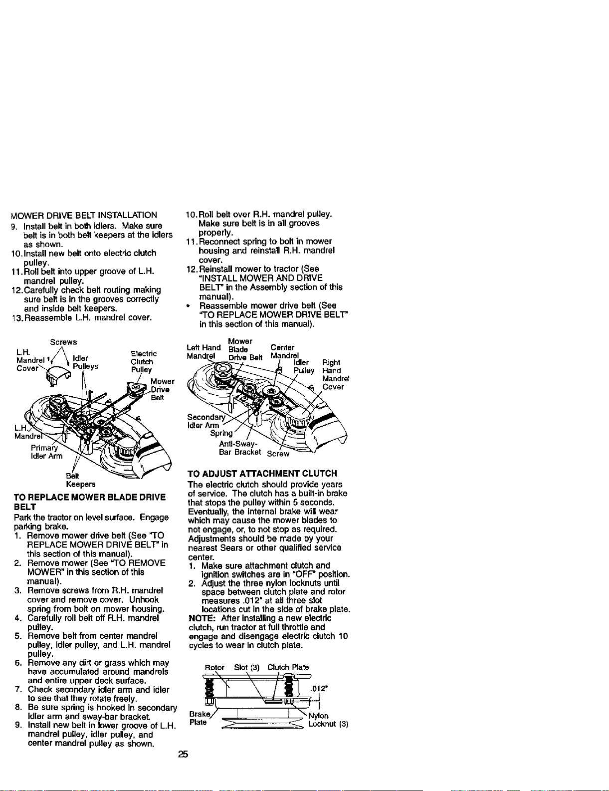
MOWER DRIVE BELT INSTALLATION
9. Install belt in both idlers. Make sure
belt is in both bolt keepers at the idlers
as shown.
10.Install new belt onto electric clutch
pulley.
11. Roll belt intoupper groove of L.H.
mandrel pulley.
12.Carefully check belt routingmaking
sure belt is in the grooves correctly
and inside belt keepers.
13.Reassemble L.H, mandrel cover.
lO.Roll belt over R.H. mandrel pulley.
Make sure belt is in all grooves
properly.
11.Reconnect spring to bolt in mower
housing and reinstall R.H. mandrel
cover.
12.Reinstall mower to tractor (See
"INSTALL MOWER AND DRIVE
BELT"in the Assembly section of this
manual).
• Reassemble mower drive belt (See
"TO REPLACE MOWER DRIVE BELT*
in this section of this manual).
Screws
LH.
Mandrel I Idler
Electdc
Clutch
Pulley
Mower
Idler Arm
Keepers
TO REPLACE MOWER BLADE DRIVE
BELT
Park the tractor on level surface. Engage
parking brake.
1. Remove mower drive belt (See "TO
REPLACE MOWER DRIVE BELT* in
this section ofthis manual).
2. Remove mower (See "TO REMOVE
MOWER" in this section of this
manual).
3. Remove screws from R.H. mandrel
cover and remove cover. Unhook
springfrom bolt on mower housing.
4. Carefully roll belt off R.H. mandrel
pulley.
5. Remove belt from center mandrel
pulley, idler pulley, and L.H. mandrel
pulley.
6. Remove any dirt or grass which may
have accumulated around mandrels
and entire upper deck surface.
7. Check secondary idler arm and idler
to see that they rotate freely.
8. Be sure spring is hooked in secondary
idler arm and sway-bar bracket.
9. Install new bolt in lower groove of L.H.
mandrel pulley, idler pulley, and
center mandrel pulley as shown,
Mower
Left Hand Blade Center
Mandrel Drive Belt Mandrel
Idler
Right
Hand
Mandr_
Idler Arm
Anti-Sway-
Bar Bracket
TO ADJUST ATFACHMENT CLUTCH
The electric clutch should provide years
of service. The clutch has a built-inbrake
that stops the pulley within 5seconds.
Eventually,the internal brake will wear
which may cause the mower blades to
not engage, or, to not stop as required.
Adjustments should be made by your
nearest Sears or other qualified service
center.
1. Make sure attachment clutchand
ignition switches are in "OFF" position.
2, Adjust the three nylon Iccknuts until
space between clutchplate and rotor
measures .012" at all three slot
locations cut in the side of brake plate,
NOTE: After installinga new electric
clutch, runtractor at full throttleand
engage and disengage electric clutch 10
cycles to wear in clutch plate.
Rotor Slot(3) Cinch Plate
Brake/ ! I _ Nylon
Plate _ Locknut (3)
25
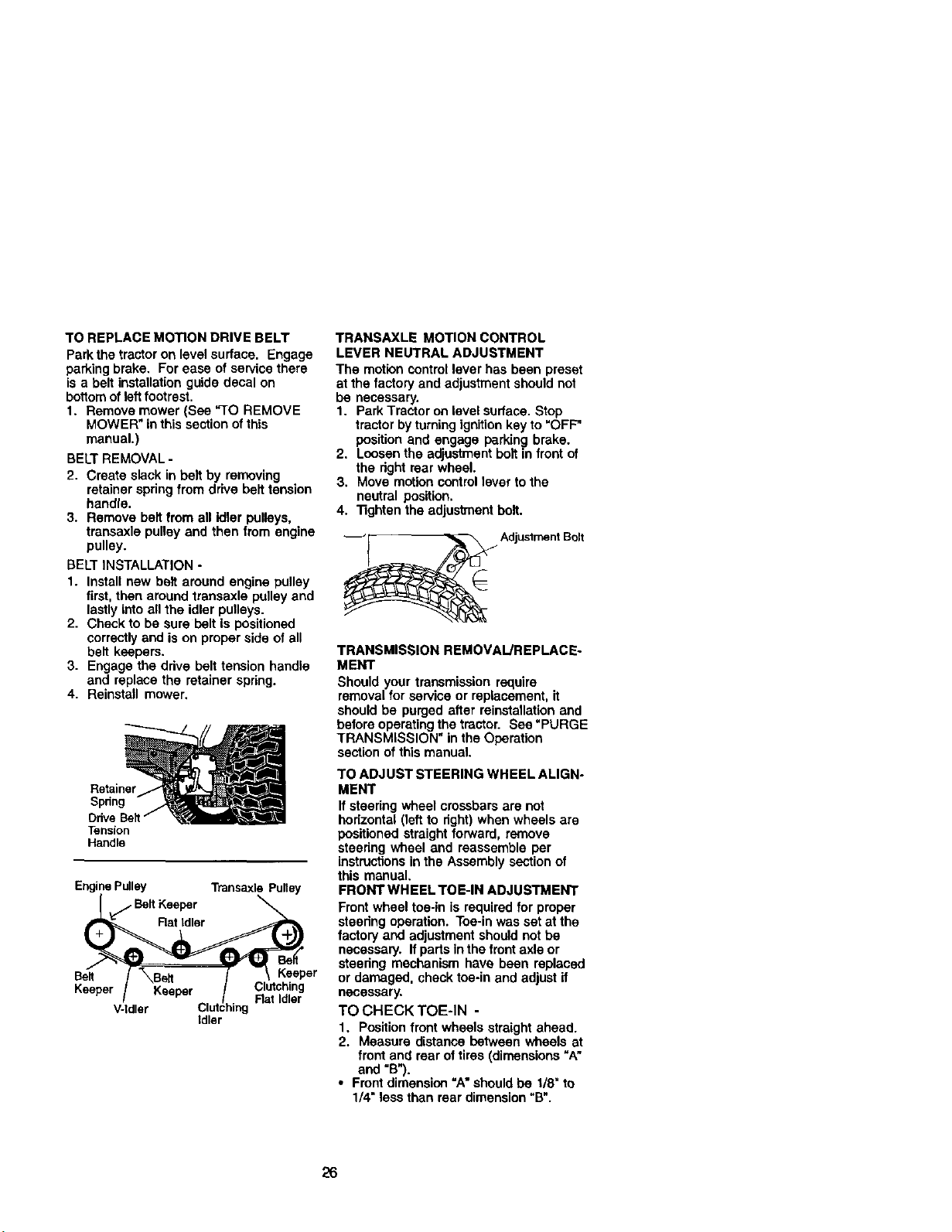
TO REPLACE MOTION DRIVE BELT
Park the tractor on level surface. Engage
parking brake. For ease of servicethere
is a belt installation guide decal on
bctlom of leftfootrest.
1. Remove mower (See "TO REMOVE
MOWER" inthis section ofthis
manual.)
BELT REMOVAL -
2. Create slack in belt by removing
retainer springfrom drive belt tension
handle.
3. Remove bell from all idler pulleys,
transaxle pulley and then from engine
pulley.
BELT INSTALLATION -
1. Install new belt around engine pulley
first, then around transaxle pulley and
lastlyinto all the idler pulleys.
2. Check to be sure belt is positioned
correctlyand is on proper side of all
bell keepers.
3. Engage the drive belt tension handle
and replace the retainer spring.
4. Reinstall mower.
Retainer
Spdng
Ddve
Tension
Handle
Engine Pulley Transaxle Pulley
.. Belt Keeper
Rat Idler
Belt \Bert Keeper
Keeper Clutching
Rat Idler
V-Idler
Idler
TRANSAXLE MOTION CONTROL
LEVER NEUTRAL ADJUSTMENT
The motioncontrol lever has been preset
at the factory and adjustment should not
be necessary.
1. Park Tractor on level surface. Stop
tractor by turningignitionkey to "OFF"
position and engage parking brake.
2. Loosen the adjustment boltin front of
the right rear wheel.
3. Move motion controllever tothe
neutral position.
4. Tighten the adjustmentbolt.
_ Adjustment Bolt
TRANSMISSION REMOVAIJREPLACE°
MENT
Should your transmission require
removal for service or replacement, it
should be purged after reinstallation and
beforeoperating the tractor. See "PURGE
TRANSMISSION" in the Operation
section of this manual.
TO ADJ UST STEERING WHEEL ALIGN-
MENT
If steering wheel crossbars are not
horizontal (left to right)when wheels are
positioned straight forward, remove
steering wheel and reassemble per
instructionsin the Assembly section of
this manual.
FRONT WHEEL TOE-IN ADJUSTMENT
Front wheel toe-in is required for proper
steering operation. Toe-in was set at the
factory and adjustment should notbe
necessary. If parts in the frontaxle or
steering mechanism have been replaced
or damaged, check toe-in and adjust if
necessary.
TO CHECK TOE-IN -
1. Positionfront wheels straight ahead.
2. Measure distance between wheels at
front and rear of tires (dimensions"A"
and "B").
• Front dimension "A"should be 1/8" to
1/4" less than rear dimension"B".
26
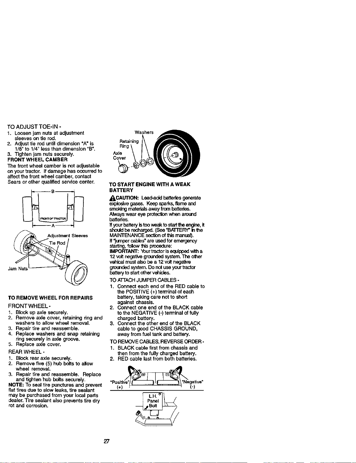
TO ADJUST TOE-IN -
1. Loosen jam nuts at adjustment
sleeves on tie rod.
2. Adjust tie rod until dimension "A" is
1/8" to 1/4" less than dimension "B".
3. Tighten jam nuts securely.
FRONT WHEEL CAMBER
The front wheel camber is not adjustable
on your tractor. Ifdamage has occurredto
affect the front wheel camber, contact
Sears or other qualifiedservice center.
Jam Nuts
TO REMOVE WHEEL FOR REPAIRS
FRONT WHEEL-
1. Block up axle securely.
2. Remove axle cover, retaining ring and
washers to allow wheel removal.
3. Repair tire and reassemble.
4. Replace washers and snap rctaining
ring securely in axle groove.
5. Replace axle cover.
REAR WHEEL -
1. Block rear axle securely.
2. Remove five (5) hub bolts to allow
wheel removal.
3. Repair tire and reassemble. Replace
and tighten hub bolts securely.
NOTE: To seal tire punctures and prevent
flat tires due to slow leaks, tire sealant
may be purchased from your local parts
dealer. Tire sealant also prevents tire dry
rot and corrosion.
Washers__
Retaining
I\ Irff? \II
TO START ENGINE WITH A WEAK
BA'FI'ERY
_I_CAU11ON: Lead-addbatteriesgenerate
explosive gases. Keep sparks,flame and
smoldngmaterials away frombatteries.
Always wear eye prct_ when around
batterias.
If yourbatteryistoowaak to sterttheangine, it
should be recharged. (See=BATTERY"Inthe
MAINTENANCE sectionof this manual).
ff"jumper cables" are used for emergency
starting,foIow this procedure:
IMPORTANT: Yeertractor isequipped with a
12 volt negative grounded system.The other
v_nical must also be a 12 volt negstive
gm,,mdedsystem. Do not use yourtractor
batteryto startother vshicles.
TO A'I-EACHJUMPER CABLES -
1. Connect each end of the RED cable to
the POSITIVE (+) terminal of each
battery, taking care not to short
against chassis.
2. Connect one end of the BLACK cable
to the NEGATIVE (-) terminal of fully
charged battery.
3. Connect the other end of the BLACK
cable to good CHASSIS GROUND,
away from fuel tank and battery.
TO REMOVE CABLES, REVERSE ORDER.
1. BLACK cable first from chassis and
then from the fully charged battery.
2. RED cable last from both battedes.
27
REPLACING BA'n'ERY
_ILCAUTION: Do not short battery
terminals by allowing a wrench or any
other objectto contact both terminals at
the same time. Before connectingbattery,
remove metal bracelets, wristwatch
bands, rings, etc.
Positiveterminal must be connected first
to prevent sparkingtrom accidental
grounding.
1. Lift hood to raised position.
2. Remove terminal guard.
3. Disconnect BLACK battew cable then
RED battery cable and carefully
remove battery from tractor.
4. Install new battery with terminals in
same position as old batter_.
5. Reinstall terminal guard.
6. First connect RED battery cable to
positive (+) battery terminal with hex
bolt and keps nut as shown. Tighten
securely.
7. Connect BLACK grounding cable to
negative (-) battery terminal with
remaining hex bolt and kaps nut.
Tighten securely
8. Close terminal access doors,
9. Close hood,
Terminal Keps Nut Hex Bolt
Access
Door_sitive
Terminal _ (Red)
Guard _ Cable
J _ _Neoa_ive <BLack)
_ Cable
TO REPLACE HEADLIGHT BULB
1. Raise hood,
2. Pull bulb holder out of the hole in the
backside of the gall.
3. Replace bulb in holder and push bulb
holder securely back into the hole in
the backside of the gall.
4. Close hood,
INTERLOCKS AND RELAYS
Loose or damaged widng may cause your
tractorto run poody, stop running,or
preventitfromstarting.
• Check wiring. See electrical widng
diagram in the Repair Parts section.
TO REPLACE FUSE
Replace with 30 amp automotive-type
ping-in fuse. The fuse holderis located
behind the dash.
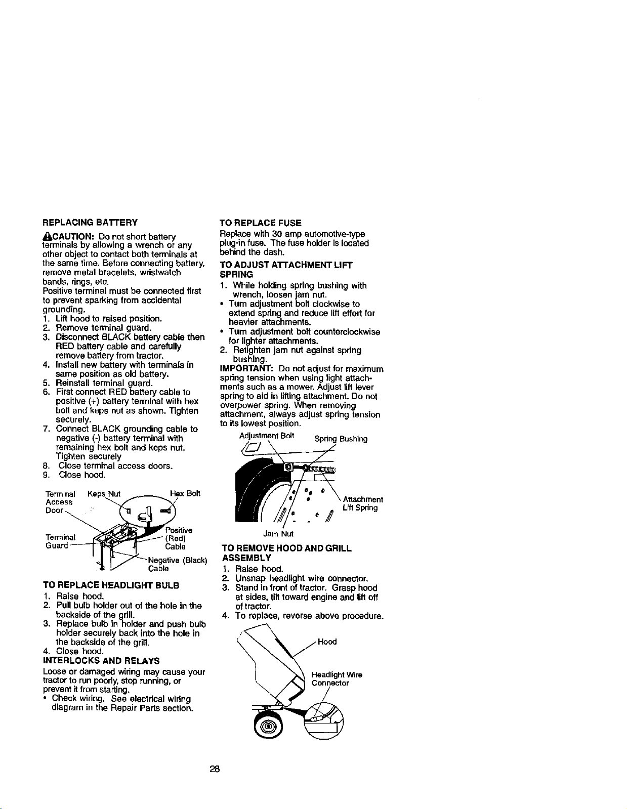
TO ADJUST A'I'rACHMEI_" L|FT
SPRING
1. While holding spdng bushing with
wrench, loosen jam nut.
• Turn adjustment belt clockwiseto
extend spdng and reduce lifteffortfor
heavier attachments,
• Turn adjustment bolt countamlockwisa
for lighter attachments.
2. Retighten jam nut against spdng
bushing.
IMPORTANT; Do not adjust for maximum
spdng tension when using light attach-
ments such as a mower. Adjust liftlever
spring to aid in lifting attachment. Do not
overpower spdng. When removing
attachment, always adjtistspringtensien
to its lowest position.
AdjustmentBolt Spnng Bushing
Attachment
LiftSpring
°/
Jam Nut
TO REMOVE HOOD AND GRILL
ASSEMBLY
t. Raise hood.
2. Unsnap headlight wire connector.
3. Stand in frontof tractor. Grasp hood
at sides, tilttoward engine and liftoff
oftractor,
4. To replace, reverse above procedure.
28

ENGINE
Maintenance, repair, or replacement of
the emission control devices and sys-
tems, which are being done at the
customers expense, may be performed
by any non-road engine repair establish-
ment or individual. Warranty repairs must
be performed by an authorized engine
manufacturer's service outlet.
TO ADJUST THRO'R'LE CONTROL
CABLE
The throttle control has been preset at the
factory and adjustment should not be
necessary. Check adjustment as de-
scribed below before loosening cable. If
adjustment is necessary, proceed as
follows:
1. With engine not running, move throttle
control leverto fast position.
2. Check that speed controllever is
against stop screw. If it isnot, loosen
casing clamp screw and pull throttle
cable until lever Is against screw.
Tighten clamp screw securely.
Idle Fuel Idle Speed
Adjusting Needle i Screw
TO ADJUST CHOKE CONTROL
The choke control has been preset at the
factory and adjustment should not be
necessary, check adjustment as described
below before loosening cable. If adjust-
ment is necessary, proceed as follows:
1. With engine not running, move choke
control (located on dash panel) to full
choke position.
2. Remove air cleaner cover, filter and
cartridge plate to expose carburetor
choke (See =AIR FILTER" in the
Maintenance section of this manual).
3. Choke should be closed. If it Is not,
loosen casing clamp screw and move
choke cable until choke is completely
closed. Tighten casing clamp screw
securely.
4. Reassemble air cleaner.
Closed For
Choke
"hrottle
Control
Cable
Stop Screw
Screw
Choke
Control
29
TO ADJUST CARBURETOR
The carburetorhas been present at the
factory and adjustment should not be
necessary, However, minor adjustment
may be required to compensate for
differences in fuel, temperature, altitude
or load. If the carburetor does need
adjustment, proceed as follows:
In general, turningthe adjusting needles
in (clockwise) decreases the supply of
fuel to the engine giving a leaner fueVair
mixture. Turningthe adjusting needles out
(counterclockwise) increases the supply
of fuel to the engine giving a richerfuel/
air mixture.
IMPORTANT: Damage to the needles
and the seats in carburetor may result if
screw isturned intoo tight.
PRELIMINARY SET-I'ING -
1. Be sure you have a clean air filter, and
the throttlecontrol cable is adjusted
properly (see "TO ADJUST
THROTrLE CONTROL CABLE" inthe
Service and Adjustments section of
this manual).
2. With engine off tum idle fuel adjusting
needle In (clockwise) closing it finger
tight and then turn out (counterclock-
wise) 1 turn.
FINAL SETTING -
1. Start engine and allow to warm for five
minutes. Make final adjustments with
engine running and shift/motion
control lever in neutral (N) position.
NOTE: The high idle is set at the factory
and cannot be adjusted.
2. Idle speed settina - With throttle
control lever in slow position, engine
should idle at 1200 RPM. If engine
idles too slow or fast, turn idle speed
adjusting screw in or out until correct
idle is attained.
3. Idle fuel needle settina - With throttle
control lever in slow position, turn idle
fuel adjusting needle In (clockwise)
until engine speed decreases and
then turn out (counterclockwise)
approximately 3/4 turn to obtainthe
best low speed performance.
4. Recheck idle speed. Readjust if
necessary.
ACCELERATION TEST -
5. Move throttle control lever from slow to
fast position. If engine hesitates or
dies, turn idle fuel adjusting needle
out (counterclockwise) 1/8 turn.
Repeat test and continue to adjust, if
necessary, until engine accelerates
smoothly.
High speed stop isfactory adjusted. Do
not adjust-damage may result.
IMPORTANT: Never tamper with the
engine governor, which is factory set for
proper engine speed. Overspeeding the
engine above the factory high speed
setting can be dangerous. If you think the
engine-governed high speed needs
adjusting, contact your nearest Sears or
other qualified service center, which has
proper equipment and experience to
make any necessary adjustments.
3O
immediately prepare your tractor for
storage at the end of the season or if the
tractor willnot be used for 30 days or
more.
A CAUTION: Never store the tractor with
gasoline in the tank inside a building
where fumes may reach an open flame or
spark. Allow the engine to cool before
stodng in any enclosure.
TRACTOR
Remove mower from tractor for winter
storage. When mower isto be stored for
a period of time, clean it thoroughly,
remove all dirt, grease, leaves, etc. Store
in a clean, dry area.
1. Clean entire tractor (See "CLEANING"
in the Maintenance section of this
manual).
2. Inspect and replace belts, if necessary
(See belt replacement instructionsin
the Service and Adjustments section
ofthis manual).
3. Lubdcata as shown in the Mainte-
nance section ofthis manual.
4. Be sure that all nuts, bolts and screws
are securely fastened. Inspect moving
parts for damage, breakage and wear.
Replace if necessary.
5. Touch up all rusted or chipped point
surfaces; sand lightlybefore painting.
BA'rrERY
• Fully charge the batteryfor storage.
• After a periodoftime in storage, battery
may require recharging.
• To help prevent corrosionand power
leakage dudng long pedods of storage,
battery cables should be disconnected
and battery cleaned thoroughly (see
"TO CLEAN BATrERY AND TERMI-
NALS" in the Maintenance sectionof
this manual).
• After cleaning, leave cables discon-
nected and place cables where they
cannot come in contactwith battery
terminals.
, If battery is removed from tractorfor
storage, do not store batterydirectly on
concrete or damp surfaces.
ENGINE
FUEL SYSTEM
iMPORTANT: It isimportantto prevent
:]um deposifes from forming in essential
!uel system parts such as carburetor,fuel
_ose, or tank during storage.
Also, expedanca indicates that alcohol
blended fuels (called gasohol or using
ethanol or methanol) can attract moisture
which leads to separation and formation
of acids dudng storage. Acidic gas can
damage the fuel system of and engine
while in storage.
1. Drain the fuel tank.
2. Start the engine and let it run until the
fuel lines and carburetor are empty.
• Never use engine or carburetor cleaner
products in the fuel tank or permanent
damage may occur.
• Use fresh fuel next season.
NOTE: Fuel stabilizer Isan acceptable
alternative in minimizing the formation of
fuel gum deposits dudng storage. Add
stabilizer to gasoline in fuel tank or
storage container. Always follow the mix
ratio found on stabilizer container. Run
engine at least 10 minutes after adding
stabilizer to allow the stabilizer to reach
the carburetor. Do not drain the gas tank
and carburetor if using fuel stabilizer.
ENGINE OIL
Drain oil (with engine warm) and replace
with clean engine oil. (See "ENGINE" in
the Maintenance section of this manual).
CYLINDER(S)
1. Remove spark plug(s).
2. Pour one ounce of oil through spark
plug hole(s) into cylinder(s).
3. Turn ignitionkey to "START" position
for a few seconds to distributeoil.
4. Replace with new spark plug(s).
OTHER
• Do not store gasoline from one season
to another.
• Replace your gasoline can if your can
starfsto rust. Rust and/or dirtin your
gasoline will cause problems.
• If possible, store your tractor indoors
and cover it to give protectionfrom dust
and dirt.
• Cover yourtractor with a suitable
protective cover that does not retain
moisture. Do not use plastic. Plastic
cannot breathe which allows conden-
sation to form and will cause your
tractor to rust.
IMPORTANT: Never cover tractor while
engine and exhaust areas are stillwarm.
31
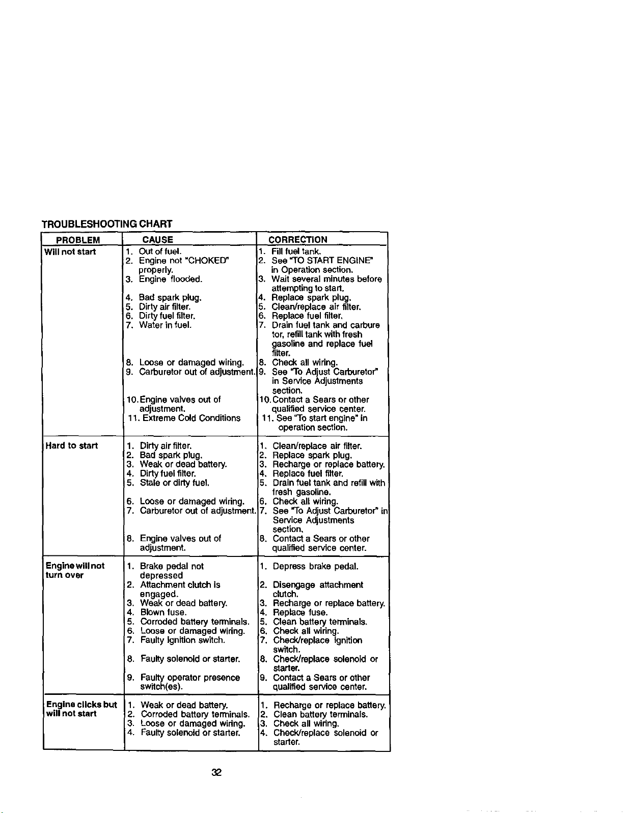
TROUBLESHOOTINGCHART
PROBLEM
Will not start 1.
2.
3.
4.
5.
6,
7.
18.
9.
Hard to start
Engine will not
turn over
Engine clicks but
will not start
CAUSE
Out offuel.
Engine not "CHOKED"
properly.
Engine flooded.
Bad spark plug.
Dirty air filter.
Dirty fuel filter.
Water in fuel.
Loose or damaged wiring.
Carburetor out of adjustment.
1O.Engine valves out of
adjustment.
11. Extreme Cold Conditions
1. Dirty air filter,
2. Bad spark plug.
3. Weak or dead battery.
4. Dirty fuel filter.
5. Stale or dirty fuel.
6. Loose or damaged wiring.
7. Carburetor out of adjustment,
8. Engine valves outof
adjustment.
1. Brake pedal not
depressed
2, Attachment clutchis
engaged.
3, Weak or dead battery,
4. Blown fuse.
5. Corroded battery terminals.
6. Loose or damaged widng.
7. Faulty ignitionswitch.
8. Faultysolenoid or starter.
9. Faultyoperatorpresence
swltch(es).
1. Weak or dead battery.
2. Corroded battery terminals.
3. Loose or damaged widng.
4. Faultysolenoid or starter.
CORRECTION
1. Fillfuel tank.
2. See =TOSTART ENGINE"
in Operation section.
3. Wait several minutes before
attempting to start.
4. Replace spark plug.
5. Clean/replace air filter.
6. Replace fuel filter,
7. Drain fuel tank and carbure
tor, refilltank withfresh
gasoline and replace fuel
rifler.
8. Check all wiring.
9, See =ToAdjust Carburetor"
in Service Adjustments
section.
1O.Cootact a Sears or other
qualified service center.
11. See =Tostartengine"in
operationsection.
1. Clean/replace air rifler.
2, Replace spark plug.
3, Recharge or replace battery.
4, Replace fuel filter.
5, Drain fuel tank and refillwith
fresh gasoline.
6. Check all wiring.
7. See "To Adjust Carburetor" in
Service Adjustments
section,
8. Contact a Sears or other
qualified service center.
1. Depress brake pedal.
12. Disengage attachment
clutch.
=3. Recharge or replace battery.
_,. Replace fuse.
5. Clean battery terminals.
S. Check all wiring.
Z. Check/replace ignition
switch.
3. Check/replace solenoid or
starter.
;_. Contact a Sears or other
qualified service center.
1. Recharge or replace battery.
2. Clean battery terminals.
3. Check all widng,
_,. Check/replace solenoid or
starter.
32
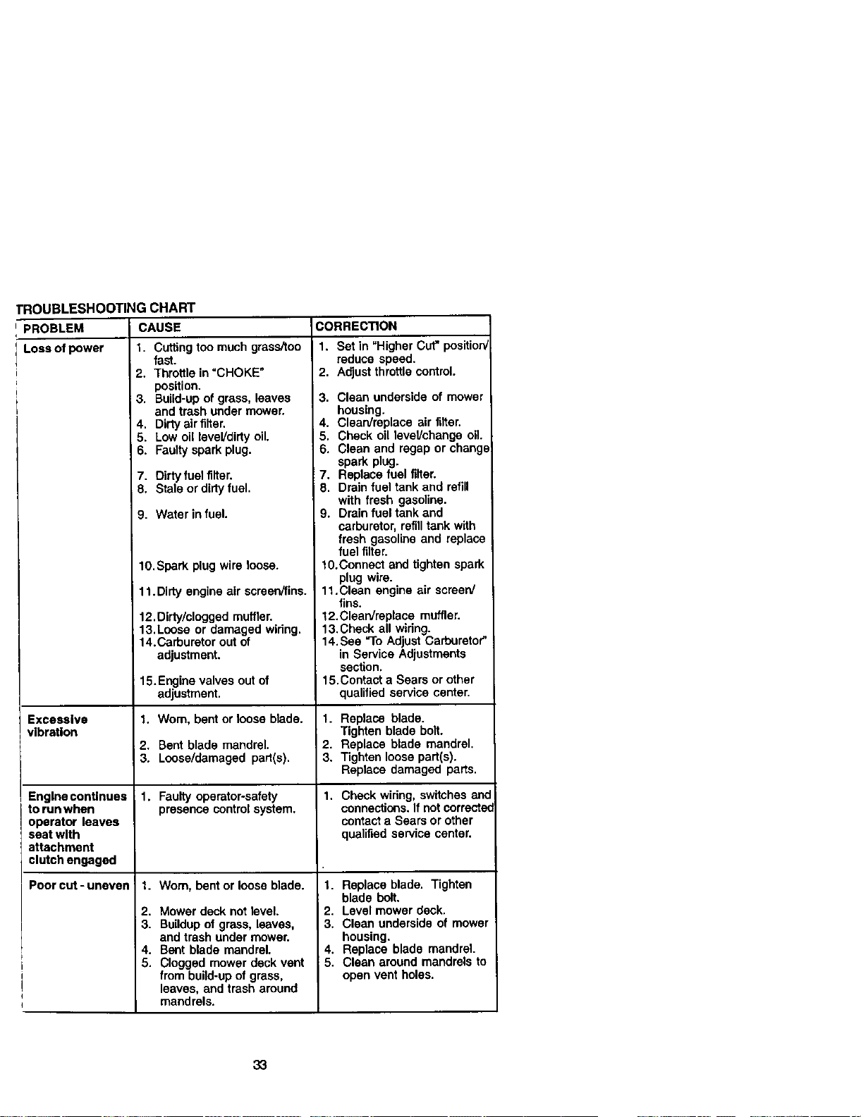
TROUBLESHOO_NG CHART
PROBLEM CAUSE CORREC_ON
Loss_power 1. Cufingtoomuchgms_oo
Excessive
vlbr_lon
Engine continues
to run when
operator leaves
seat with
attachment
clutch engaged
i
i
!
q
Poorcut-uneven =
fast.
2. Throttle in "CHOKE"
position.
3. Build-up of grass, leaves
and trash under mower.
4. Dirty airfilter.
5. Low oil level/dirty oil.
6. Faulty spark plug.
7. Dirty fuel filter.
8. Stale or dirty fuel.
9. Water in fuel.
10.Spark plug wire loose.
11.Dirty engine air screen/fins.
12.Dirty/clogged muffler.
13.Loose or damaged wiring.
14.Carburetor out of
adjustment.
15.Engine valves out of
adjustment.
1. Worn, bent or loose blade.
2. Bent blade mandrel.
3. Loose/damaged part(s).
1. Faultyoperator-safety
presence control system.
1. Wom, bent or loose blade.
2. Mower deck notlevel.
3. Buildupof grass, leaves,
and trash under mower.
4. Bent blade mandrel.
5. Clogged mower deck vent
from build-up of grass,
leaves, and trash around
mandrels.
1. Set in "Higher Cut" positiorV
reduce speed.
2. Adjustthrottlecontrol.
3. Clean underside of mower
housing.
4. Clean/replace air filter.
5. Check oil lavel/changa oil.
6. Clean and regap or cheng_
spark plug.
7. Replace fuel filter.
8. Drain fuel tank and refill
with fresh gasoline.
9. Drain fuel tank and
carburetor, refilltank with
fresh gasoline and replace
fuel filter.
10.Connect and tighten spark
plug wire.
11.Clean engine air screen/
fins.
12.Clean/replace muffler.
13.Check all wiring.
14. See "ToAdjust Carburetor"
in Service Adjustments
section.
15.Contact a Sears or other
qualified service center.
1. Replace blade.
Tighten blade bolt.
2. Replace blade mandrel.
3. Tighten loose part(s).
Replace damaged pads,
1. Check wiring, switches end
connections. If notcorrectec
contacta Sears or other
qualified service center.
1. Replace blade. Tighten
blade bolt.
2. Level mower deck.
3. Clean underside of mower
housing.
4. Replace blade mandrel.
5. Clean around mandrels to
open vent holes.
33
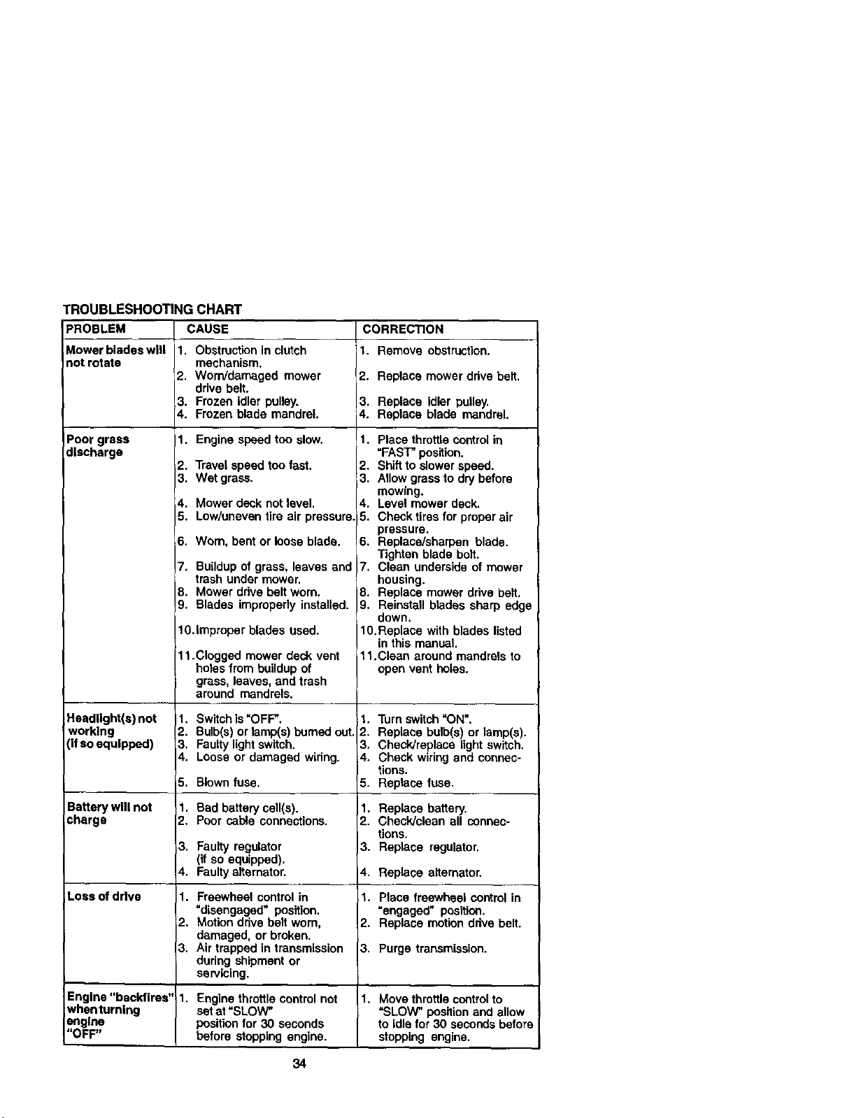
TROUBLESHOOTING CHART
PROBLEM CAUSE CORRECTION
Mower blades will 1. Obstruction in clutch 1. Remove obstruction.
not rotate mechanism.
2. Worn/damaged mower 2. Replace mower drive belt,
ddve belt.
3. Frozen idler pulley. 3. Replace idler pulley,
4. Frozen blade mandrel. 4. Replace blade mandrel.
Poor grass 1. Engine speed too slow.
discharge
Headlight(s) not
working
(if so equipped)
Battery will not
charge
Loss of drive
2. Travel speed too fast.
3. Wet gross.
4. Mower deck not level.
5. Low/uneven tire air pressure.
6. Wom, bent or loose blade.
7. Buildup of grass, leaves end
trash under mower.
8. Mower ddve belt worn.
9. Blades improperly installed.
lO.improper blades used.
11.Clogged mower deck vent
holes from buildup of
grass, leaves, and trash
around mandrels,
1. Switchis "OFF".
2. Bulb(s) or lemp(s) burned out.
3. Faulty lightswitch.
4. Loose or damaged widng.
5. Blown fuse.
1. Bad battery cell(s).
2. Poor cable connections.
3. Faulty regulator
(if so equipped).
4. Faultyalternator.
1. Freewheel control in
"disengaged" position.
2. Motion drive belt worn,
damaged, or broken.
3. Air trapped in transmission
during shipment or
sen/icing.
1. Place throttle control in
"FAST" position.
2. Shift to slower speed.
3. Allow grossto dry before
mowing.
4. Level mower deck.
5. Check tires for proper air
pressure.
6. Replace/sharpen blade.
Tighten blade bolt.
7. Clean underside of mower
housing.
8. Replace mower drive belt.
9. Reinstall blades sharp edge
down.
10.Replace with blades listed
in this manual.
11.Clean around mandrels to
open vent holes.
1. Turnswitch "ON".
2. Replace bulb(s) or lamp(s).
3. Check]replace Lightswitch.
4. Check wiring and connec-
tions.
5. Replace fuse.
1. Replace battery.
2. Check]clean all connec-
tions.
3. Replace regulator.
4. Replace alternator.
1. Place freewheel control in
=engaged" position.
2. Replace motion drive belt.
3. Purge transmission.
Engine "backfires" 1. Engine throttlecontrol not 1, Move throttlecontrolto
whenturnlng set at =SLOW" =SLOW" position and allow
engine positionfor 30 seconds to idle for 30 seconds before
"OFF" before stopping engine, stopping engine.
34
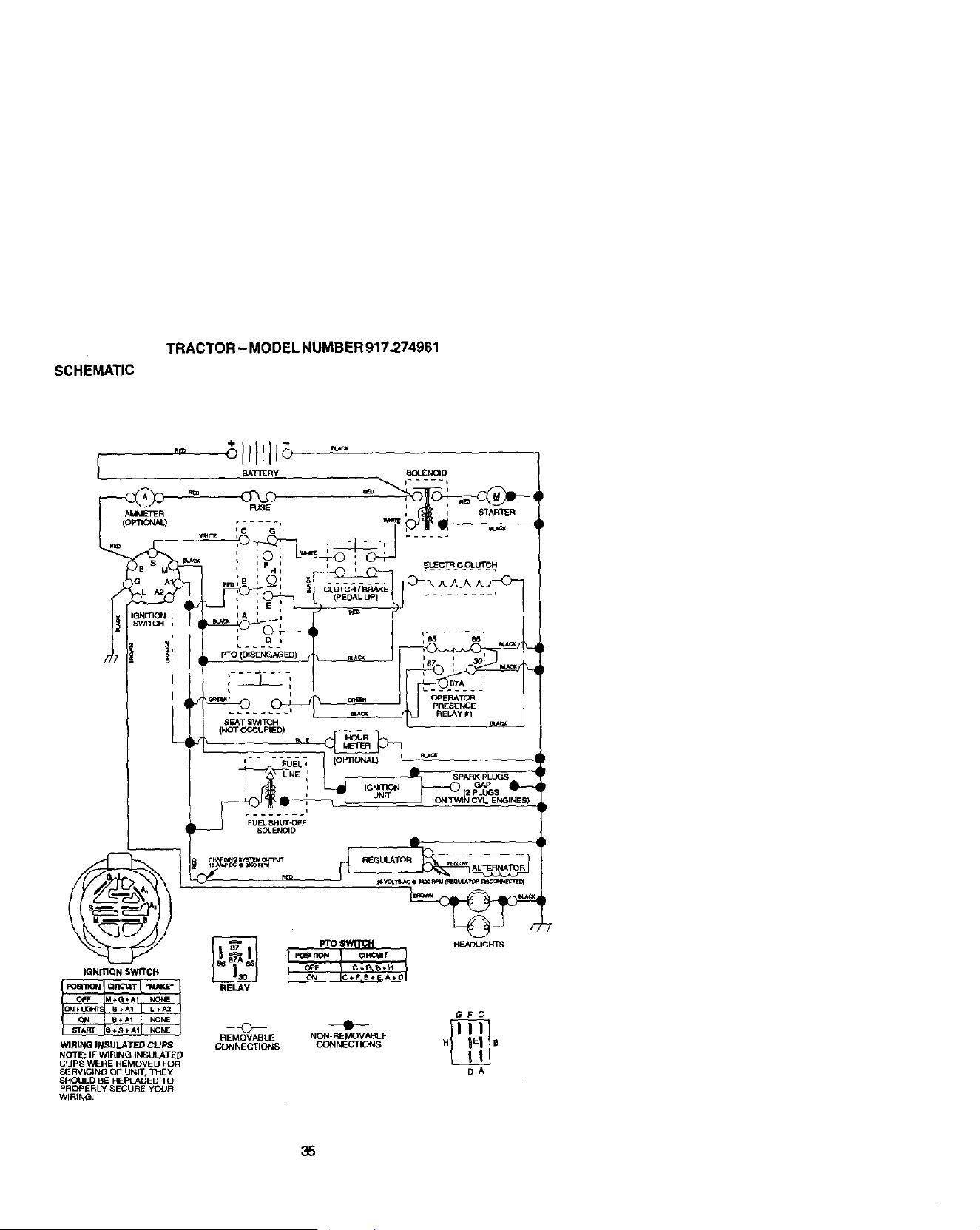
sCHEMATIC
TRACTOR - MODEL NUMBER 917,274961
35
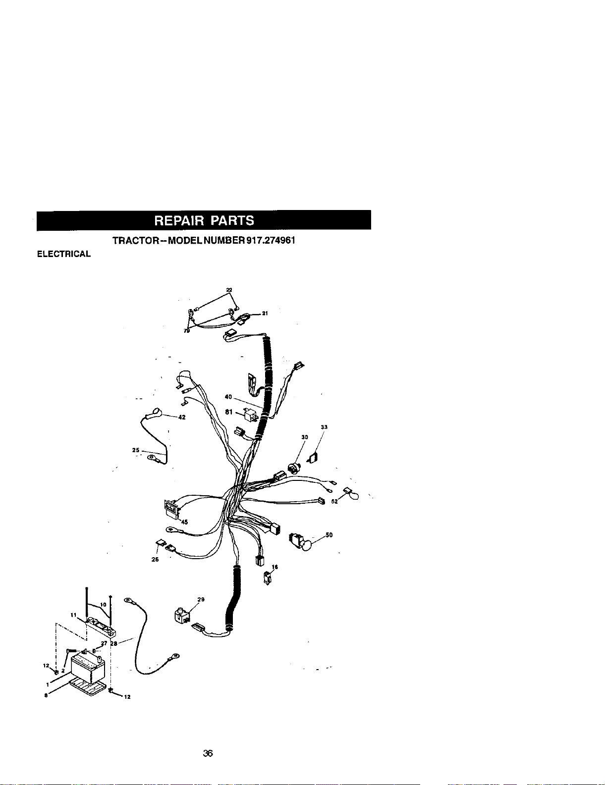
TRACTOR- MODEL NUMBER 917.274961
ELECTRICAL
22
29
36

ELECTRICAL
TRACTOR - MODEL NUMBER 917.274961
KEY PART
NO. NO. DESCRIPTION
1 144927 Baltery
2 74760412 Bo;t Hex Head 1/4-20 x 3/4
8 7603J Tray, Batter/
10 145211 Bctt 114-20 x 7.5 Zinc
11 150109 Hold down Battew Dash Mourd
12 145769 Nut Push Nylon 1/4"
16 153664 Switch Interlock Push-In
21 166184 Harness SccXet Light W 4152J
22 4152J Bulb Light
25 150755 Cable, Batten/
26 1(_824X Fuse
27 73510460 Nut Keps Hex 1/4-20 Unc
28 170697 Cable, Ground
29 160784 Switch, Plunger
30 175566 Switch, Ign
33 140403 Key, Ignition
40 170238 Harness Ign.
42 154336 Cover, Terminal
45 122822X Ammeter
50 174652 Switch, PTO
52 141940 Protection Wire Locp
79 163996 BuJbhelder
81 1(]_748X Relay Asm.
NOTE: All component dimensions g_venin U. S. Inches
1 inch = 25.4 mm
37
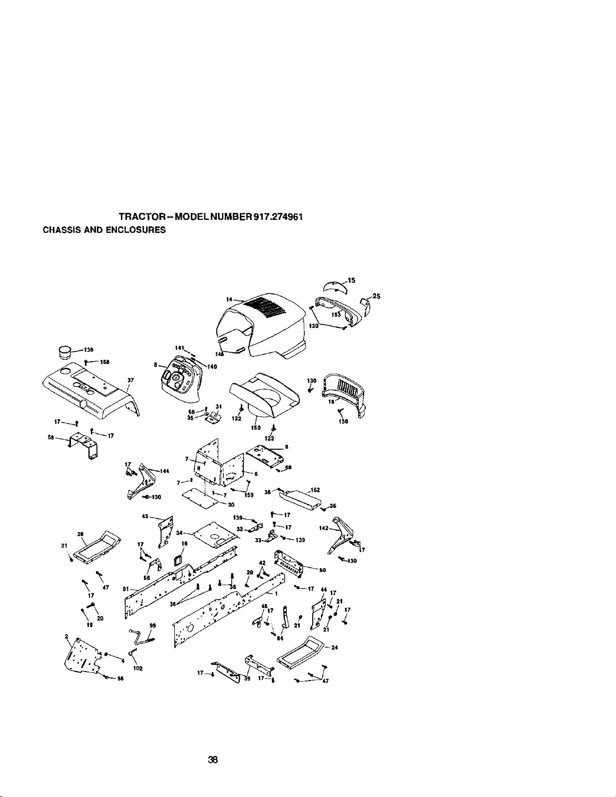
TRACTOR- MODELNUMBER917.274961
CHASSISANDENCLOSURES
138
37
141
ISO 12_
38
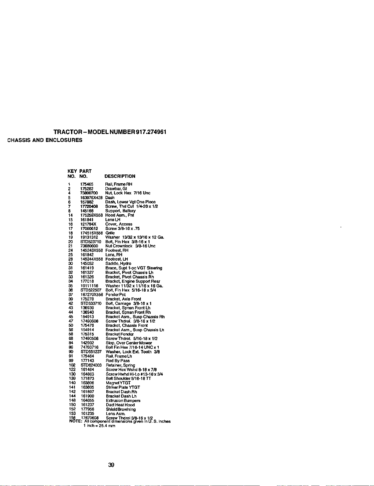
TRACTOR-MODELNUMBER917.274961
CHASSISANDENCLOSURES
KEY PART
NO. NO, DESCRIPTION
t 175465 Rail, Frame RH
2 175282 Drawhar, Gt
4 73800700 Nut, Lock Hex 7/16 Unc
5 163976X428 Dash
6 157882 Dash. Lower Vgt One Piece
7 17720408 Screw, Thd Cut 114-20 x 1/2
8 145166 Support, Battery
14 175259X558 Hood Asm., Pnt
15 161841 LensLH
16 121794X Cover, Access
17 17(;60612 Screw 3/8-19 x .75
18 174515X559 Grille
19 19131312 Washer 13/32 x 13/16 x 12 Ga.
20 $3_333710 Bolt, Fin Hex 3/8-16 x 1
21 73680600 Nut Crowrdock 3/9-16 Unc
24 145243X558 Footrest, RH
25 161842 Lens, RH
28 145244X559 Footrest, LH
30 145052 Saddle, Hydro
31 161419 Brace, Supt 1-pc VGT Steering
33 161327 Bracket, Pivot Chassis Lh
33 161336 Bracket, Pivol Chassis Rh
34 177018 Bracket, Engine Support Rear
35 19111116 Washer 11/32 x 11/16 x 16 Ga.
36 STD522507 Bott, FinHex 3/16-18x3/4
37 167270X558 Fender POt
39 175278 Bracket, Axle Front
42 STD5337"I0 Bolt, Carriage 3/8-16 x t
43 136939 BrBcket, Spnsn Front Lh
44 136940 Bracket, Spnsn Front Rh
45 154913 Bracket Asm., Susp ChessJs Rh
47 17490608 Screw ThdroL 3/8-16 x 1/2
50 175476 Bracket, ChaSSis Front
56 154914 Bracket Asm., Susp Chassis Lh
58 175315 Bracket Fender
68 17490508 Screw Thdrol. 5/16-19 x 1/2
84 142992 Stop, Over Ceoter Mower
86 74760716 Bolt FinHex 7/16-14 UNC x 1
90 STD551237 Washe_, Lock Ext. Tooth 3/8
91 175464 Rail, Frame Lh
177143 Rod ByPaSS
133 STD_40(_ Retainer, Spring
122 161464 Screw Hex Wshd 8-18 x 7/8
130 164863 Screw Hwhd HI-Lo #t 3-16 x 3/4
139 171973 BoltShoulder 5/16-18 TT
140 163806 MagnotYTGT
141 163805 Sttiker Plale YTGT
142 161897 Bracket Dash Rh
144 1619(X) Bracket Dash Lh
148 164655 Extrusion Burnpem
150 161237 Duct Heat Hood
133 177956 ShieldBrovAning
153 161235 Lens Asrn.
158 17670608 Screw Thdrol 3/_-16 x 1/2
NOTE: All component dimensions glen in U. S. Inches
1 inch= 25.4 rnm
39
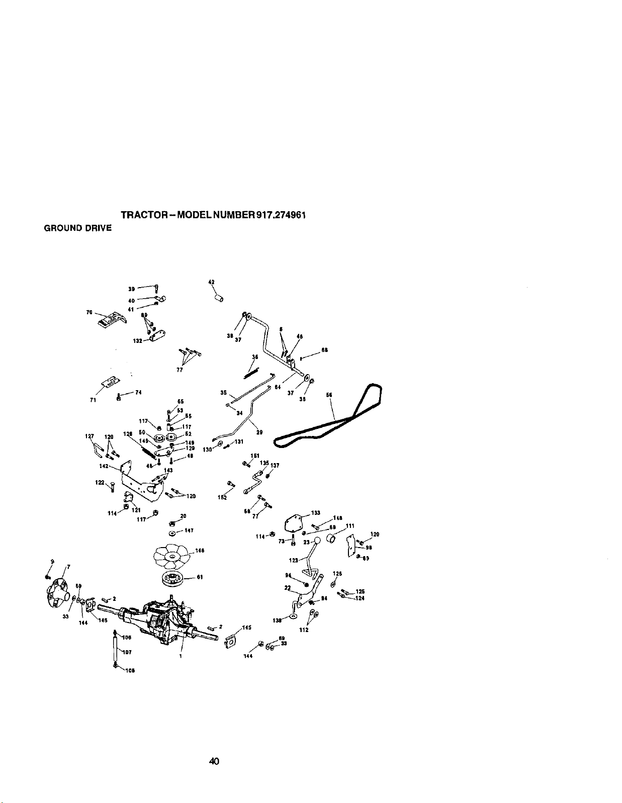
TRACTOR- MODELNUMBER917.274961
GROUNDDRIVE
144
42
71 65
_53 SS
1 7 1 0 1 il 60 62
38 37 46
161
112
144
413

TRACTOR- MODEL NUMBER 917.274961
GROUNDDRIVE
KEY PART KEY PART
NO. NO. DESCRIPTION NO. NO.
2 9396E Key Sq. 1/4 x 1/4 x 2 107 154739
6 $1_561210 Pin, Cotter 105 142918
7 14C507 Wheel, Hub Assembly 111 156240
9 140080 Boft, Hub 112 156104
20 _00 NUt 114
22 178391 Lever Asrn Shift 117 73_00600
23 130564 )0lob 120 17050512
29 176600 Brake, Red 121 175611
33 12000053 RlngE 122 72110520
34 71673 Cap, parking Brake 123 176602
35 137648 Red, Parking Brake 124 165492
36 149412 Spdng, Ddve Ground 125 166880
37 121749X Washer 25/32xl-1/4x10G& 126 166002
38 150055 Nyliner 127 1773_2
39 74,321016 Screw, Fin. #10-24xl 128 176624
40 178575 Actuator, Interlock Switch 129 178588
41 739G1000 Nut Centerlock 16-24 Uric 130 19131016
42 8883R Cover, Pedal 131 76020312
46 145170 Retalner, Spring 132 175467
48 72110614 Bolt, Carri. 3/8-16 x 1-3/4 Gr. 5 133 175468
50 131494 Pulley, Idler, Fiat 135 177364
52 127783 Pulley, Idler, Grooved 137 1685H
53 207J Washer, Hardened 138 1370H
55 105705X Beadng, Idler 142 175469
56 161597 V-Belt 143 17050512
58 74760724 Bolt Fin Hex 7/16-14 x 1-1/2 144 160848
61 1_5 Pulley, Transaxle 145 163168
64 176601 Shalt, ClutcWBrake Pedal 146 140462
65 67609 Bolt, Shoulder 147 141322
_8 std571912 Pin, Roll 148 17050516
6g 123800X Washer 149 19131410
70 164892X428 ConsoleAutornatlcYT/GT 151 74760514
71 151179 Plate Console Shift 152 178705
73 74490548 Bolt Hex Flghd 5/16-18 x 3 Gr. 5 -- 176056
74 142432 Screw Hex Wsh. Hi-Lo 1/4-1/2
77 74760716 BoRFin Hex 7/16-14 x 1
89 73680700 NutCrownlock 7/16-14 Unc
94 133805 Fastener Christmas Tree
98 141004 Bracket Shift
105 142917 Cap Asm Vent Hydro
DESCRIPTION
Line Fuel Hydro 15"
O-Ring Asm. Hydro
Spacer Shilt Lever VGTH
Washer Nylon HighTemp
Nut LockHex w/lns 5/16-18 Unc
Nut, Lock Fig. 3/8-16
Screw 3/8-16 x .75
Bracket Strap Torque
Bdt RdHd Sq 5/16-18 Unc x 2ol/2
Rod Shi_t
Bolt shoLdder5/16-18 x.561
Screw 5/16-18 x 5/8
Washer Srdd 5/16 ID x 1.0 x .125
Link Control Clutch
Spring Drive Grnd
Bracket Asm Idler Tensioning
Washer 13/32 x 5/8 x 16 Ga.
Pin Cotter 3/32 x 3/4
Bracket Mtg. Hydro 3500 Lh Vgt
Bracket Mtg. Hydro 0500 Rh Vgt
Link Asrn Control Hydro 3500
Nut Lock 5/16-18 Nc Thd
Washer Thrust 5/8 x 1.10 x 1/82
StrapTorque HG-3500
Screw Thdrol 5/16-18 x 3/4
Wa.sder Spacer Axle HG-30QO
Wa.sherAxle Flange HG_30GO
Fan 7" Hydro
Washer
Screw Thdrol3/8-16 x 1
Washer 13/32 x 7/8 x 10 Ga_
Bolt Fin Hex 5/16-18 x 3/4
Bolt Hex 5/16-19 x 1 w/Patch
Transaxle Hydro Gear 331-3000
NOTE: All component dimensions given inU. S. Inches
1 inch = 25.4 mm
41

STEERING
TRACTOR- MODEL NUMBER 917,274961
23
31
/
/
16
/
\
\
\
\
'\
\
\ {
42

STEERING
TRACTOR- MODEL NUMBER 917.274961
KEY PART
NO. NO. DESCRIPTION
1 139768 Wheel, Steerlng
2 178557 Axle Asm., Front
3 6855M Fitting, Grease
4 t61849 Spindle AXm, LH
5 181848 Spinole Asm., RH
6 6266H Bearing,Race "llvust Harden
7 121748X Washer 28/3_ x %5/8 x 16 G&
8 12000029 Ring,Klip#T5304-75
9 121232_X Cap, Spindle
10 74781044 Bait, FLnHex 3/8-11 x 2-3/4
11 136518 Spacer Beadng Axle Front
12 73901000 Nut, Lock Flange 5/8-11 Uric
13 121749X Washer 25/32 x 1-1/4 x 16 Ga.
14 STD551137 Washer, LockHvyHIctSpr 3/8
15 STD541537 Nut, LockCenter 3/8-24 UNF
16 145109 Shaft Asm., Steering
17 137347 Rod Asm., ]]e Vgt (Inc. Key No. 38-40)
18 175572 Dragllnk, Ball Joint Soiid Vgt
19 156011 Support Asm., Steedng Vgt
20 172020 Beet, Steering
21 100711L Adapter, Wheel Steeheg
22 155105 Bushing, Strg. B_k
23 152927 Screw
24 19133812 Washer
25 74780616 Boit, Fin Hex 3/8-16 x 1 Gr. 5
26 139769 Cap, Wheel Steering
27 3366R Bearing, Col. Strg.
28 17000612 Screw 5/8-18 x 5/4
29 104239x Beadng, Flange
30 1200_029 RlngCllp
3t 138136 Bushing, Nyllner Snap
32 19111610 Washer 11/32 x 1 x 10 Ga.
33 STD551131 Washer, Lock I-Ny Hlcl Spr 5/16
34 74780512 Bait, Hex Hd 3/16-18 x 3/4
35 138059 Gear, Sector Steering
36 137156 Tie Rod
37 73360600 Jam Nut RH "t'_ead
38 109850X Joint Asm. Ball RH Thread
39 73700600 Nut Hex Jam 3/8-24 Unf LH
40 109851X Joint Asm LH
41 155246 Bracket SYnch Interlock VGT 97
42 174905(_ Screw Thdrol 5/18-18 x 1/2 Tyt
46 178291 Spacer
47 177863 Bracket Asrn. Idler Stat_onaP/
48 17060612 Screw 3/8-18 x 3/4
49 1314.94 Pulley Idler Flat
50 73900600 Nut Lock Fig. 3/8-16
NOTE: All component dimensions given in U. S.
inches 1 inch = 25.4 mm
43
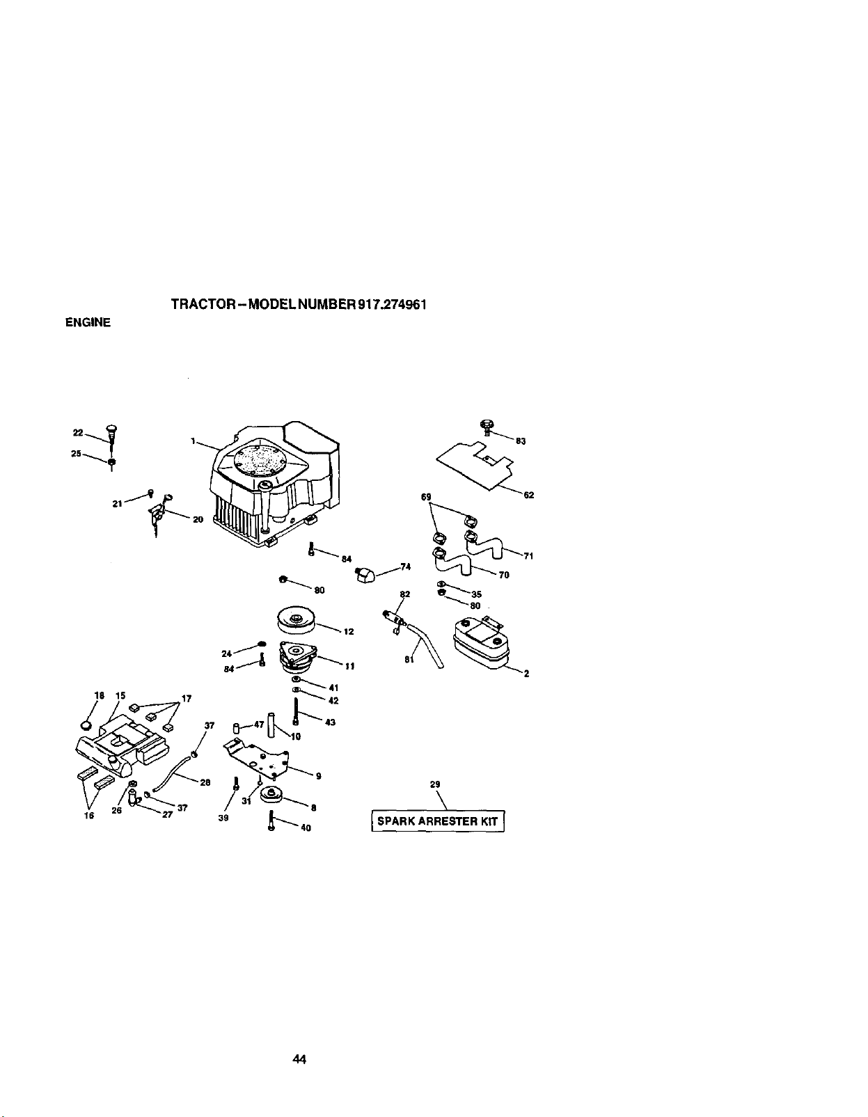
ENGINE
TRACTOR - MODEL NUMBER 917.274961
18 15 17
37
16
8O
69 52
29
\
I SPARK ARRESTER KIT J
44

ENGINE
TRACTOR - MODEL NUMBER 917.274961
KEY PART
NO. NO, DESCRIPTION
1 ...... Engine (See Breakdown)
Kshler Model No.CV624-65577
2
8
9
10
11
12
15
16
17
18
20
21
22
24
25
26
27
28
29
31
35
37
3g
4O
41
42
43
47
62
6g
70
71
74
8O
81
82
83
84
149723 Muffler
121361X Puliey V÷ldhir
177748 Keeper Asm. Belt Engine
175288 Bushing
170056 Clutch Electdc
143996 Pu_ey Engine VGT Ehict Clutsh
151346 Tan}( Fuel Rear 3,50 Yt/Gt 96
10_27X Pad Spacer
106082X Pad Spacer
140527 Cap Asm Fuel W/Gauge
1T/328X428 ControlThrottle
164863 Screw Hwhd HI-Lo #13-16 x 3/4
175441X428 ControlChoke
STD551237 Wasber Ext Tooth 3/8
73_0600 Nut Keps 3/8 - 24 UNF
3645J Bushing
139277 StemTank Fuel
7834R FueiUne
137180 Spark Arrester Kit
1450(36 Clip
10010500 Washer Split
123487X ClampH6_e
17490636 Screw "t-r 3_-16 x 2-1/4 UNC
174OO664 Screw Ti" 3/8-16 x 4 UNC
1261973( Washer 1-1/2 (30 X 15/32 ID X .250
STD551143 Washer Lock 7/16
173937 Bclt 7/16-20 x 4 Gr. 5
175287 Bushing
14O629 Shield Heat Muffler CV-Intek
24-041-02 Gasket Kohler CV18-CV26
175545 Tube Exhaust Lh
175546 Tube Exhaust Rh
162295 Elbow Street Brass
M73C3OS(X3 Nut Flange M8-1.25 Non-Lk Zlnk
148456 Tube Drain Oil Easy
148315 Plug Drain OII EaSy
171877 Bolt 5/16-18 Unc x 3/4 w/eerns
17490624 Screw Thdrol 3/8-16 x 1-1/2
NOTE: All component dimensions given in U. S. inches
1 inch= 25.4 mm
45
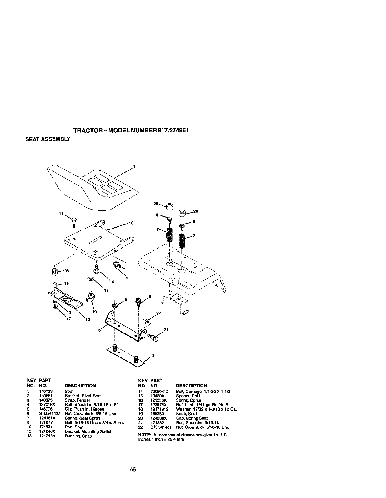
TRACTOR-MODELNUMBER917.274961
SEATASSEMBLY
KEY pART
NO, NO. DESCRIPTION
1 140123 Seat
2 140651 Bracket, pivot Seat
3 14_675 Strap, Fender
4 127018X Bolt, Shoulder 5/16-18 x .62
5 145006 Clip, PUSh In, Hinged
6 $3D541437 Nut, Crownlock 3_-16 Unc
7 124151X Spdng, Seat Cpr_tt
8 171877 Bolt 5/16-18 Unc x _4 w Serns
10 174894 Pan, Seat
12 121246X Bracket, Mounting Switch
13 t21248X Bushing, Snap
KEY PART
NO. NO. DESCRIPTION
14 72050412 Bolt, Caniage 1/4-20 X 1-1/2
15 134300 Spacer, Split
16 121250X Spring, Cprsn
17 123_76X Nut, Lock 1/4 Lge Fig Gr. 5
18 19171912 Washer 17/32 x 1-3J16 x 12 Ga.
19 166369 Knob, Seat
20 124238X Cap, Spdng Seat
21 t71852 Bolt, Shoulder 5/16-18
22 STD541431 Nut, Crownlock 5/16-18 Unc
NOTE: All component (_mensions given in U. S.
inches 1 inch = 25.4 mm
46
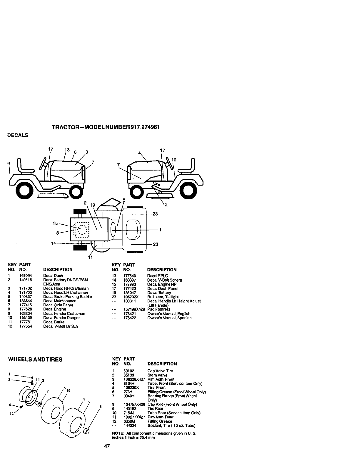
DECALS
TRACTOR - MODEL NUMBER 917.274961
17
7
17
12
KEY PART
NO. NO.
1 164_4
2 149516
3 1717(_
4 171703
5 14_837
8 133644
7 177415
5 177628
9 163204
10 156439
11 177781
12 177554
11
KEY PART
DESCRIPTION NO. NO. DESCRIPTION
DecalDash 13 177540 DeCalRPLC
Decal Battery DNGR/PSN 14 1603.97 Decal V-Belt Schem
ENGAsm 15 178993 OecalEngine Hp
Decal Hood RH CraJtsman 17 177423 DecaJDash Panel
Decal Hood LHCraftsman 19 138047 Decal Batted/
Decal Broke Par kingSaddle 23 101_02X Reltectm, Taillight
Decal MaJntenance - - 138311 Decal Handle Lft Height Adjust
Decal Side Panel (Lilt Handle)
Decal Engine -- 157199X428 pad Footmet
DecaJFender Craftsman -- 178421 Owner's Manual, Engllsh
Decal Fender Danger -- 178422 Owner's Manual, Spanish
Decal Brake
Decal V-Belt Dr Sch
WHEELS ANDTIRES
4
7 10
47
KEY PART
NO, NO. DESCRIPTION
1 59192 Cap Valve ]]re
2 65139 Stem Valve
3 106228X427 RImAsm Front
4 81:341"1 Tube, Front (Sewtce Item Only)
5 10_230X "llre, Front
6 278H FittingGrease (Front Wheel Only)
7 904GH Beadng Flange (FrontW1_eel
8 104757X428 Cap Axle (Front Wheel Only)
9 140183 13reReal
10 7154,J Tube Rear (Service Item Only)
11 106277X427 RimAsm Rear
12 685&_ F_lng Grease
o- 144334 Sealant, ]]re ( 10 oz. Tube)
NOTE: All componerd dimensions given in U. S.
inches 1 inch = 25.4 mm
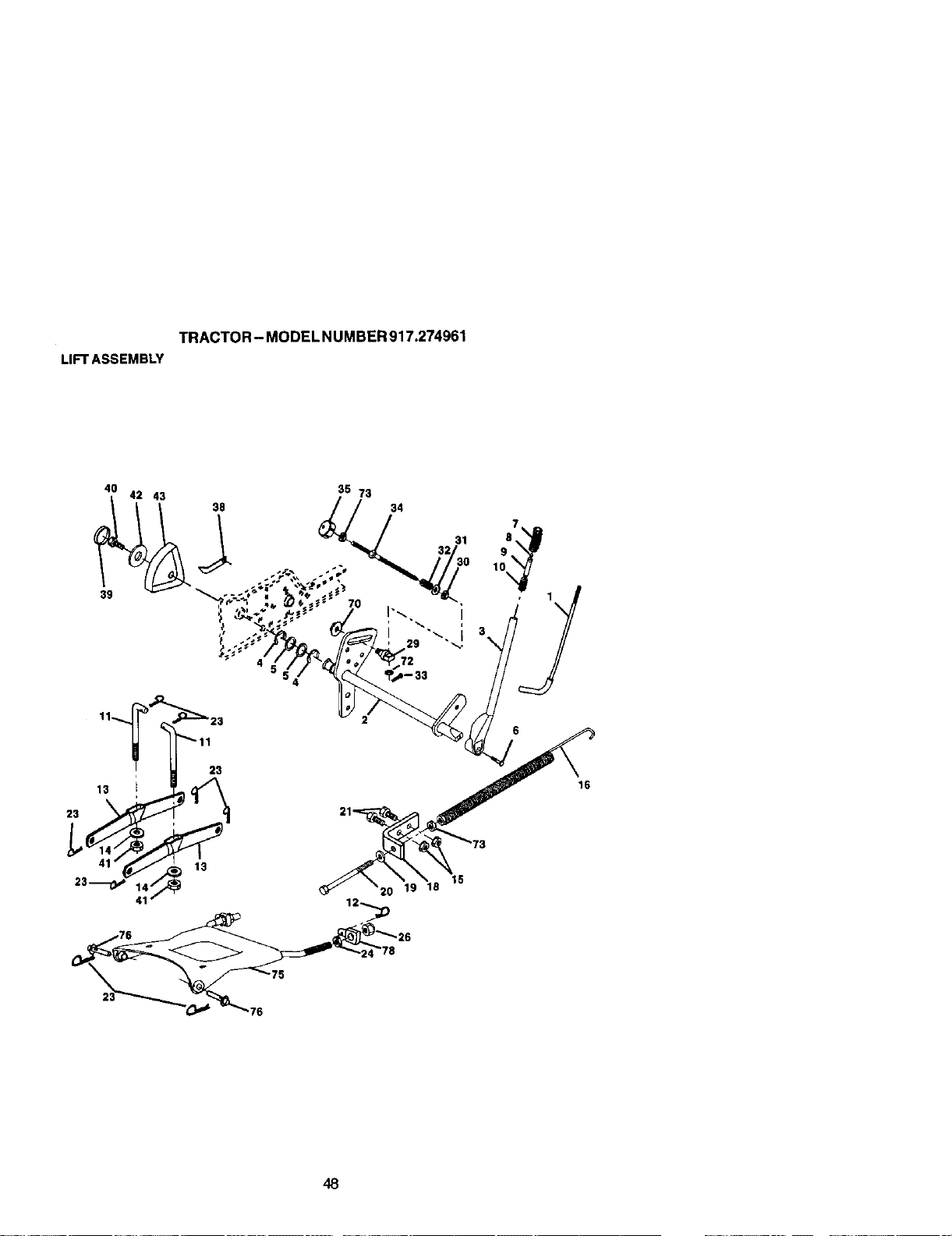
TRACTOR - MODEL NUMBER 917.274961
LIFTASSEMBLY
4O
39
42 43
38
35 73
7
32 31 8
9
0 10
• 1
I'_ ]
"_.. 3\
20 19 18
15
16
48

TRACTOR-MODELNUMBER917.274961
LIFTASSEMBLY
KEY PART
NO. NO. DESCRIPTION
1 121006X Rod Asm., Lever
2 177535 Shatt Asm., Lift Vgt
3 159189 Lever Asm., Ult Rh
4 12(_00022 E*Ring Truarc #5133-87
5 19292016 Washer 29/32 x t-1/4 x 16 Ga.
6 71110624 BoR, Fin Hex 3/8-16 x 1-1/2
7 125631X Gdp, Handle Fluted
8 122365X Button,Plunger
9 122364X plunger, Lever Lilt
10 287eH Spring 2-1/8"
11 146704 Link Lift
12 163552 Retainer, Spdng
13 139868 Arm, Suspension Vgt
14 169865 Bearing
15 $3D541437 Nut, Crowstock 3/B-16 Uric
16 674A247 Spring Asm., Assist Ll(t
18 143363 Bmcket. Spdng Assist
19 $1D551037 Washer 13/32x13/16xt6Ga.
20 5328J Bolt, Adjust Spring Assist
21 STD523710 Bolt, Pin Hex 3/8-16 x 1
24 73350800 Nut, Jam Hex 1/2-t3 Uric
26 73680800 NutCrownlock 1/2°13 Unc
29 150233 Trunnion, Infin Height
30 110807X NuL Specia]
31 STD551037 Washer 13/32xS/Sx16Ga.
32 137150 Spring, Compression Ird Hgt
33 ST10_0907 Pin, Cotter 3/32 x 1/2
34 137167 Rod, Adj Lift
35 138057 Knob, Inf 3/8-16 Uric
38 155097 Pointer, Height Indicator
39 123935X Plug, Hole
40 17060516 Screw 5/16-18 x 1
41 73540600 Nut. Crowrdock 3/8-24
42 19112410 Washer 11/32 x 1-1/2 x 10 Ga.
43 123934X Scale, indicator Height
70 145212 Nut Hex Flange Lock
72 110452X Nut Push Phos & Oil
73 STD54'L237 Nut Hex Jam 3/8-16 Unc
75 175805 Plate Asm Front
76 175560 PinFlar_ge
78 175689 Trunnl(xl
NOTE: All component dimensions given in U. S. inches
1 Inch = 25.4 mm
49
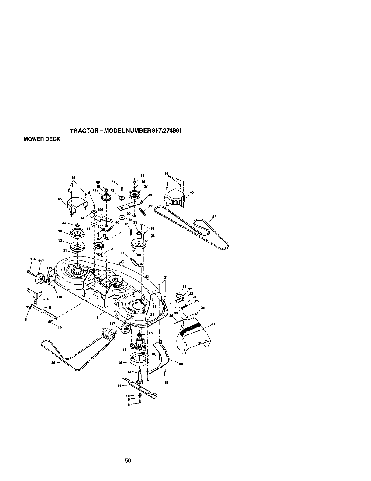
TRACTOR-MODELNUMBER917.274961
MOWERDECK
4$
46
49 41
4g
46
47
117
21
28
5O

TRACTOR-MODELNUMBER917.274961
MOWERDECK
KEY PART KEY PART
NO. NO. DESCRIPTION NO. NO. DESCRIPTION
1 156948 DeckWeldrnentMower 46 36 19131316 Washer 13/32 x 13/16 x 16 Ga.
3 1384,57 Bracket Asm., Sway Bar 37 131494 Pulley, Idler, Flat
5 4939M RetainerSpdng 38 156086 Keeper, Belt, Idler
6 130832 Arm, Suspension, Rear (Sway 38 144917 Pulley, idler, Driven
Bar) 40 137273 Spdng, Seconda W 44/46]50 Vent
8 850857 Bett, Patch 3/6-24 x 1-1/4 Gr. 8 41 1_ Screw 3/6-16 x 1-1/4
9 $1_551137 washer, LockHW, Unplated 3/8 42 165723 Spacer, Retainer
10 140296 Washer, Hard Blade, Mower 43 144949 Arm, idler Secondaly
Vented 44 133943 Washer, Hardened
11 176084 Blade, 46" 45 145059 Cover, Mandrel Deck
13 137553 Shelf Asm. w/Lower Bearing 46 137729 Screw, Thdroll. 1/4-20 x 5/8
14 137152 Housing, Mandrel 47 14495g V-Belt, Mower, SecondaP/
15 110485X Beadng, Ball, Mandrel 48 148763 V-Bail, Mower, PrlrnaW
16 174493 Stripper, Mower Round 49 73680600 Nut, Crownleck 3/6-16 UNC
18 72140505 Bo_LCarriage 5/16-18x5/8 50 72110612 Bolt, Carr. 3/8-16x 1-1/2Gr. 5
19 13_827 Bolt, Hex Hd, Shoulder 5/16-18 52 156493 PulLey Idler46 Pd Drive 97
20 145055 Baffle, Vo:tex Mower 46" 72 19131616 Washer 13/32 x 1 x 16 Ga.
21 73680500 Nut. Crownlock 5/16-18 UNC 116 137644 Bolt, Shoulck._r
22 134753 Sttffiner, Bracket 117 133957 GaugeWheeI,WIde
23 131267 Bracket, Detidetor 118 73,.q_0600 Nut, Centedock 3,/6-15UNC
24 105304X Cap, Sleeve 119 19121414 Washer 3/8 x 7/8 x 14 Ga.
25 149287 Spdng, Torsion, Deflector 126 144948 Arrn, Idler, P6man/Deck 46"
26 110452X Nut, Push 127 146763 Pulley, Idler, V-Groove Dim. 4.25
27 166883X428 Defleetor Clipping -- 166209 ReplacementMo,,_ r,Complete
28 19111016 Washer 11/32x5/8x16Ga. -- 143651 MandrelAsm. Service
29 131491 Rod, Hidge (Includes Key Nos. 8o10, 13-15,
30 157722 Screw, TndretlWasher Head 31 and 33)
31 129963 Washer, Spacer Mower Vented
32 153531 Pulley, Mandrel
33 178342 Nut, Fig. Top Lock
34 144945 Anchor, Spdng Deck 46" NOTS: AI_component dimensions given in U. S. inches
35 1749_628 Screw, Thdroll 3/6-I6 x 1-3/4Tylt 1 Inch= 25.4 mm
51

TRACTOR-MODELNUMBER917.274961
TRANSAXLE-MODELNUMBER331-3000
I
52

TRACTOR-MODELNUMBER917,274961
TRANSAXLE-MODELNUMBER331-3000
KEY PARr _'Y PARr
NO. NO. DESCRIP]ION NO. NO. DESCRIPI_0N
1 161122 Math HousingAssembly 74 169535 Batl Brg 6205-1
2 178317 R.H. HousingAssembly 75 161157 Seal 1"ldX 2.0472" X 0.375"
3 169522 Center Section Assembly 76 161153 Shaft, Axte
4 161125 Spacer 77 142884 Washer
5 1429_. SeaJ-LIp 79 178322 Gasket Matodal
6 142928 Wire Ratalnlng Ring 80 161159 Ton< Head Screw, 5/16-18
7 142933 Retaining Ring 81 161160 Needle Bearing (Sce1412)
8 142934 BallBeadng 82 161161 W_;ha=2
9 169523 Cradle Bearing 83 161162 Retateing Ring
10 169524 Vadable Swashplate 84 161163 LipSeat
11 150771 Thrdat Beadug 30 X 52 X 13 (0.8751.D.X 1.3o.D.X0.25
12 161126 input Shaft 85 161164 Brake Disk
13 142978 Block Thrust Washar 87 178323 Washer
14 142977 Arm.Trunnion 88 178324 ScrewS/16-24
15 196050 10cc Cylinpar eJock 89 178325 Beadng
Assembly 90 178326 Spacer
21 169525 21cc Cylinder Block 91 169536 Odng, 0.070 X 0.239
Assembly 93 178327 Screw
24 161127 Output (Motor) Shaft 93 142969 Spdng, Fdc6on Pack
25 169526 Thrust Beadng 42 X 66 X 16 94 142980 Spacer, FrlcttenPack
26 161126 Conb'atArm 95 169537 Hex Lock Nut 5/16-24
27 161129 Spacer 96 169538 Sleeve Bearing
28 161130 16t Pinion Gear 97 150798 Oil
29 169527 Capscrew, M6 X 1-22 106 161166 Spacer, Trur_Jon
30 142941 Slat Gutpa 108 178328 Plug
31 161132 TrunnionArm 110 142916 Fittlng-O Ring Ass'y
93 161133 TrunnionBushiug 111 142917 .,_ Cap Vent Ass'y
33 142940 LipSeat 116 169539 Retaining Ring
34 178318 Arm Ratum 117 161168 Std Hdls Pin
35 178319 ArrnActuating 120 142883 Puck, Brake
36 169933 5/16-24 Stud 121 169540 Rib Neck Bolt, 2"
37 142967 puck, Fdc6on 122 178329 Brake Yoke
38 150787 Bypass Plate 124 178330 Arm, Brake
39 169529 Bypass Actuator 125 142887 Pins, Brake
40 142945 LIpSeal 126 161172 Lockwasher, 1/4"
41 142952 Bypass Arrn 127 161173 Nut, 1/4-20
42 142953 Rctaining Rtug 128 142885 Nut, Castle
43 142965 Pin 129 142866 Cotter Pin
44 150797 Screw 130 161174 Spacer
48 178320 Puck 131 142882 Puck Plate
50 178343 Screw_SelfTappiug 132 169544 Rib Neck Bott,3" 1
51 169530 Lower Cover 134 178331 Spdng
52 169531 Gerotor Assembly 136 178332 Spdng Extension
53 144581 O-Ring 137 178333 P_nSpt'ng
54 161139 GerotorCover 138 178334 BoltSelf Tapping
55 178321 Filter 139 161176 Washer, 7/8_1X 0.265id X 0.125
56 169533 Charge Manifold
57 161142 Retainer, Motor Bearlug 141 178335 SprJugBrake
58 161143 Pin, Cartier 144 169545 O Ring, 2.864 Id X 0.070 TOk
59 161144 151Planet Gear 145 169546 Spring, Relief
69 161145 7t Spur Gear 146 169547 Ball, 7/16
61 161146 211Sun Gear 151 161181 Comp. Spring, Brake Anti-Drag
69 161147 Planet Thrust Plate 152 178336 Brake PuffRod
63 161148 511Ring Gear 153 142914 plug, StraightThread
64 161149 Planatai'./Ca rder 155 178337 KitFan
65 161150 Miter Gear, Diff. (Splined) 157 169548 Screw O-R!ng
66 161151 M_terGear, Diff. 180 169549 Maniteld Kit
67 161152 Shaft, DifferentlaJ 203 178338 KitSeal
68 161153 Diff ThnJst Plate 900 166773 Transaxle, complete
69 169534 Flange Beming
70 161154 Washer NOTE: AJlcomponent dimensions given in U.S. inches
71 161155 Washer 1 inch = 25.4 mm
73 161156 Hex Jam Nut, 5/8-16
53
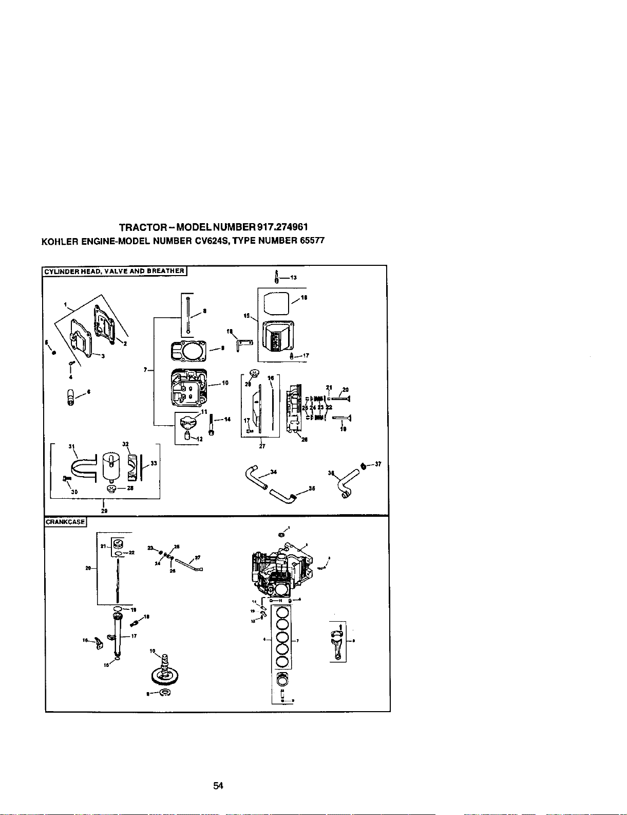
TRACTOR- MODEL NUMBER 917.274961
KOHLERENGINE-MODELNUMBERCV624S,TYPENUMBER65577
CYLINDER HEAD, VALVE AND BREATHER I
_D13
4
7-
/I
Q
t3
I
2m
1_ ,pIla
54
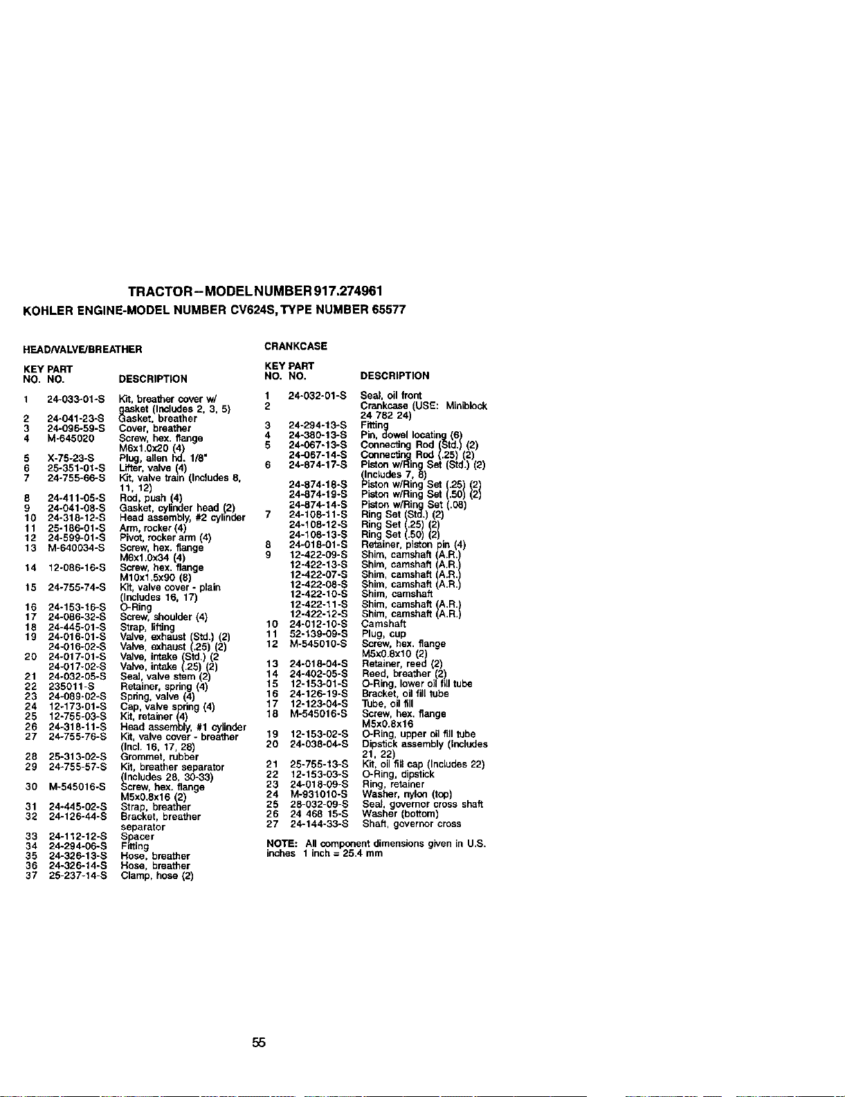
TRACTOR-MODELNUMBER917.274961
KOHLERENGINE-MODELNUMBERCV624S,TYPENUMBER65577
HEAD/VALVE/BREATHER
CRANKCASE
KEY PART KEY PART
NO. NO. DESCRIPTION NO. NO. DESCRIPTION
1 24-033-01-S Kit, breather cover w/ 1 24-032-01-S Seal, oil front
_asket (Includes 2, 3, 5) 2 Crankcase USE: Mialblock
2 24-041-23-S L_asket, breather 24 782 24
3 24-096-59-S Cover, breather 3 24-294-13-S Fittin
4 M-645020 Screw, hex. flange 4 24-380-13-S Pin, o_owallocating (6)
M6xl.0x20 (4) 5 24-067-13-S Connecting Rod (Std.) (2)
5 X-75-23-S Ph_J, allen hd. 1/8" 24-067-14-S Connecting Rod (.25) (2)
Piston w/Ring Set (Std.) (2)
6 25-351-01-S Lifter, valve (4 6 24-874-17-S (Inaludes 7, 8
7 24-755-66-S Kit, valve train nc udes 8,
1,12) 248,418sP,=oow/R,ngso1251121
5 24-411-05-S Rod, push (4) 24-874-19-S piston w/Ring Set .50 2
24-041-08-S Gasket, cylinder head 12) 24-874-14-S Piston wiRing Set .08)
90 24-318-12-S Head assembly, #2 cylinder 7 24-108-11-S Ring Set (Std. 2
11 25-186-01-S Arm, rocker 4) 24-108-12-S Ring Set (.25) (2)
12 24-599-01-S Pvot, rocker arm (4) 24-105-13-S Ring Set (.50) (2)
13 M-640034-S Screw. hex. flange 8 24-018-01 -S Retainer, piston pin (4)
M6x1.0x34 (4) 9 12-422-09-S Shim, camshaft IA.R. I
14 12-086-16-S Screw, hex. flange 12-422-13-S Shim, camshaft A.R.
M10x1.5x90 (8) 12-422-07-S Shim, camshaft I_IA.R.
15 24-755-74-S Kit, valve cover - plain 12-422-08-S Shim, camshaft .R.
(Includes 16, 17) 12-422-10-S Shim, camshaft
18 24-153-16-S O-Ring 12-422-11-S Shim, camshaft }A.R. I
17 24-086-32-S Screw, shoulder (4) 12-422-12-S Shim, camshaft A.R.
15 24-445-01-S Strap, lifting 10 24-012-10-S Camshaft
19 24-016-01-S Valve, exhaust (Std.) (2) 11 52-139-09-S Plug, cup
24-016-02-S Valve, exhaust (.25) (2) 12 M-545010-S Screw, hex. flange
20 24-017-01-S Valve, intake (Std.) (2 M5x0.Sxl0 (2)
24-017-02-S Valve, intake (.25) (2) 13 24-018-04-S Retainer, reed (2)
21 24-032-05-S Seal, valve stem (2) 14 24-402-05-S Reed, breather (2)
22 235011-S Retainer, spring (4) 15 12-153-01-S O-Ring, lower oil fill tube
23 24-089-02-S Spring, valve (4) 16 24-126-19-S Bracket, oil fill tube
24 12-173-01-S Cap, valve spring 4 17 12-123-04-S Tube, oil fill
25 12-755-03-S Kit, retainer (4) 18 M-545016-S Screw, hex. flange
26 24-318-11-S Head assembly, #1 cylinder M5xO.Sx16
27 24-755-76-S Kit, valve cover- breather 19 12-153-02-S O-Ring, upper oil fill tube
(Incl. 16, 17, 28) 20 24-038-04-S Dipstick assembly (includes
28 25-313-02-S Grommet. rubber 21. 22)
29 24-755-57-S Kit, breather separator 21 25-755-13-S Kit. oil fill cap (Includes 22)
(Includes 28, 30-33) 22 12-153-03-S O-Ring, dipstick
30 M-545016-S Screw, hex. flange 23 24-018-09-S Ring, retainer
24 M-931010-S Washer, nylon (top)
M5x0.Sx16 (2)
31 24-445-02-S Strap, breather 28 28-032-09-S Seal, governor cross shaft
32 24-126-44-S Bracket, breather 26 24 468 15-S Washer (bottom)
separator 27 24-144-33-S Shaft, governor cross
33 24-112-12-S Spacer
34 24-294-06-S Fralng NOTE: All component dimensions given in U.S.
35 24-326-13-S Hose. breather inches 1 inch = 25.4 mm
36 24-326-14-S Hose, breather
37 25-237-14-S Clamp, hose (2)
55
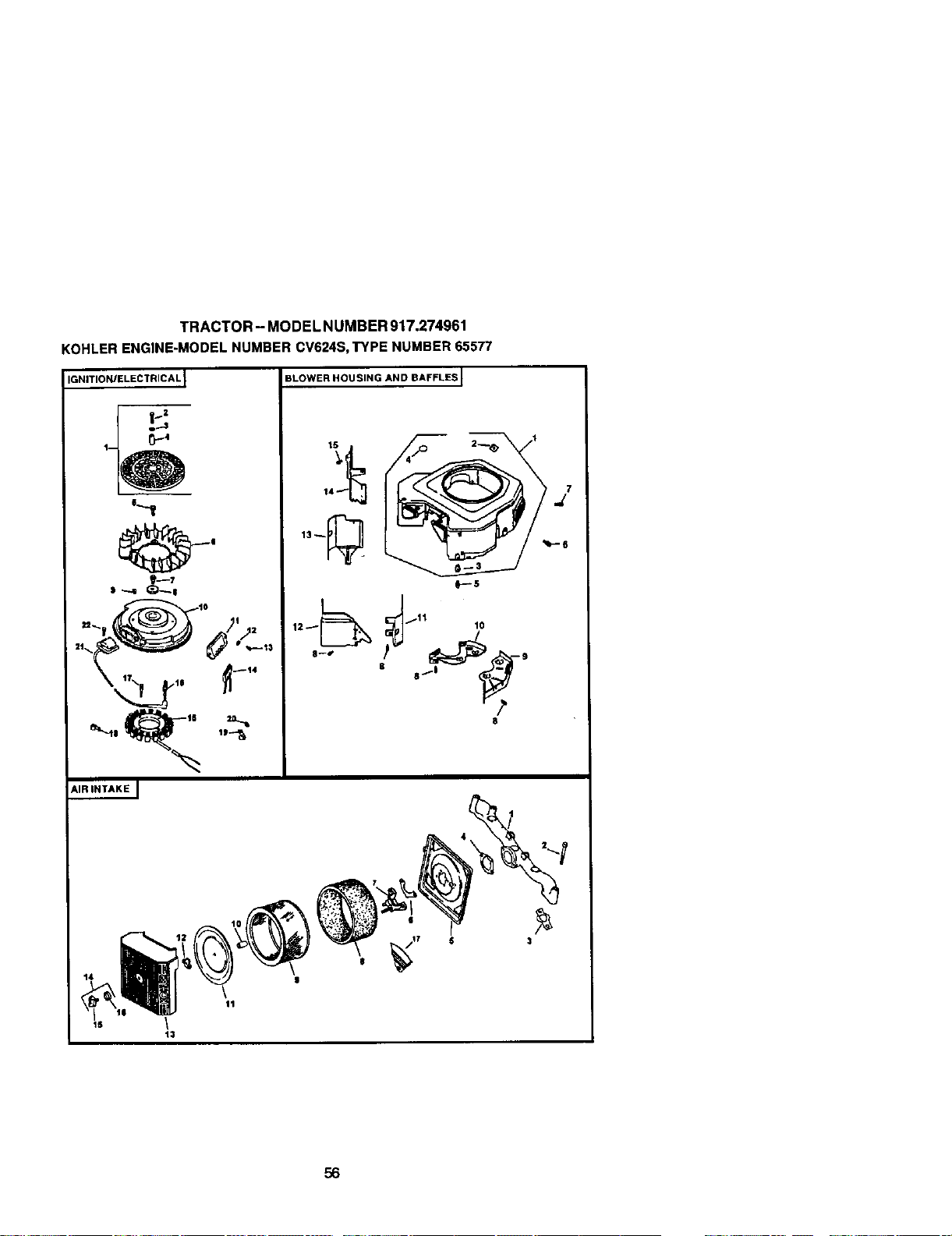
TRACTOR- MODEL NUMBER 917.274961
KOHLERENGINE-MODELNUMBERCV624S,TYPE NUMBER65577
_NITION/ELECTRICAL I
_-,,_ ,,_
AIR INTAKE J
BLOWER HOUSING AND BAFFLES I
e---5
8
56
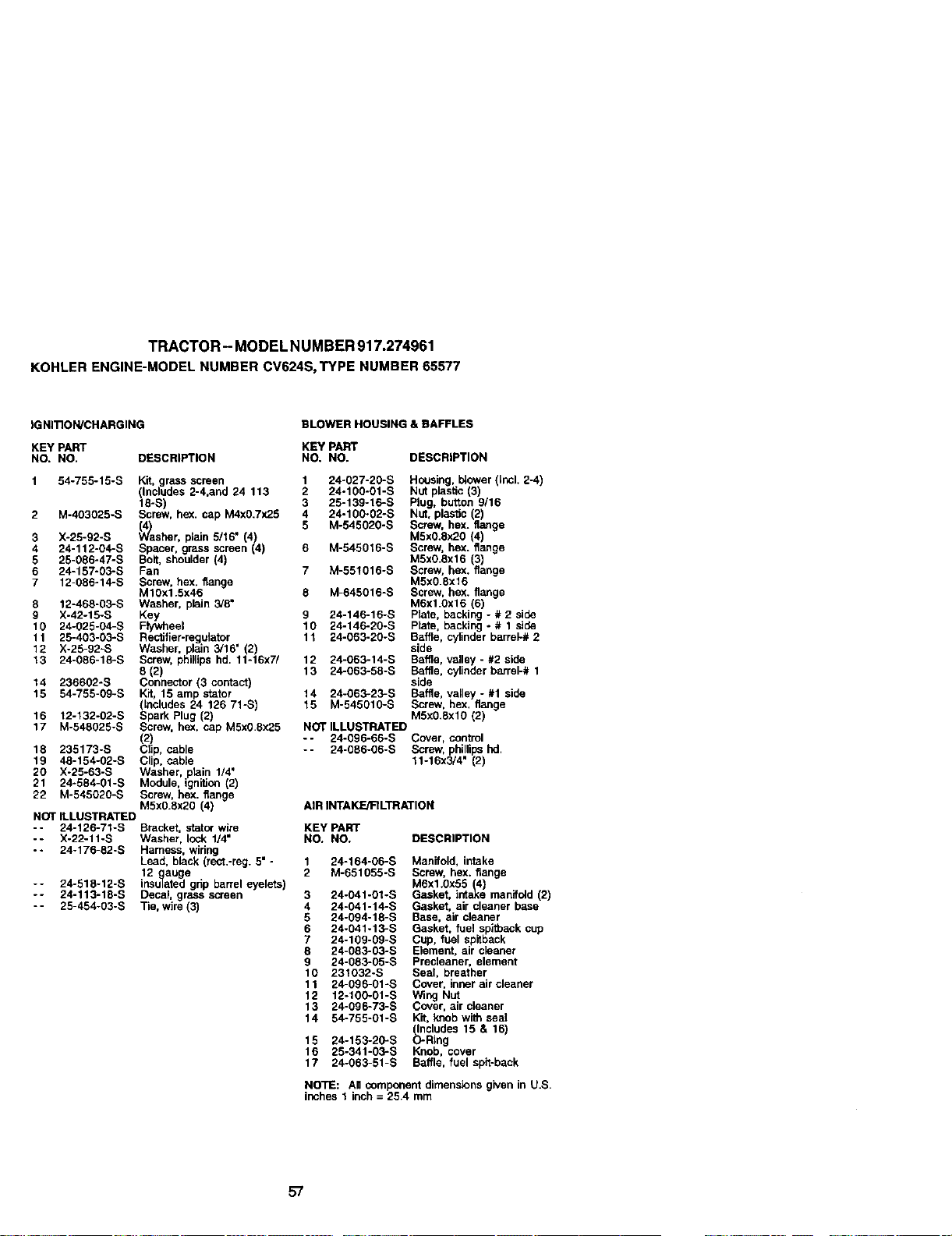
TRACTOR- MODELNUMBER917.274961
KOHLERENGINE-MODELNUMBERCV624S,TYPENUMBER65577
IGNITION/CHARGING BLOWER HOUSING & BAFFLES
KEY PART KEY PART
NO, NO. DESCRIPTION NO. NO. DESCRIPTION
1 54-755-15-S Kit, grass screen 1 24-027-20-S Housing, I_ower (_ncl. 2-4)
(Includes 2-4,and 24 113 2 24-100-01-S Nut plastic (3)
18-S) 3 25-139-16-S Plug. button 9/16
2 M-403025-S Screw, hex. cap M4x0.7x25 4 24-100-02-S Nut, plastic (2)
5 M-545020-S Screw, hex. flange
3 X-25-92-S sher, plain 5116" 4) M5x0.8x20 (4)
4 24-112-04-S Spacer, grass screen (4) 6 M-545016-S Screw, hex. flange
5 25-086-47-S Bolt, shoulder (4) M5x0itx16 (3)
6 24-157-03-S Fan 7 M-55!016-S Screw. hex. flange
7 12-086-14-S Screw, hex. flange M5x0 8x16
M10xl 5x46 8 M-645016-S Screw, hex. flange
8 12-468-03-S Washer, plain 3/8" M6x10x16 (6)
9 X-42-15-S Key 9 24-146-16-S Plate, backing - # 2 side
10 24-025-04-S FF/wheel 10 24-146-20-S Plate, backing - # 1 side
11 25-403-03-S Rectifier-regolator 11 24-063-20-S Baffle, cylinder barrel-# 2
12 X-25-92-S Washer, plain 3/16" (2) side
13 24-086-18-S Screw, phillips hd. 11-16x7/ 12 24-063-14-S Baffle, valley - #2 side
8 (2) 13 24-063-58-S Baffle, cylinder barrel-# 1
14 236602-S Connector (3 contact) side
15 54-755-09-S Kit, 15 amp stator 14 24-063-23-S Baffle, valley - #1 side
(includes 24 126 71-S) 15 M-545010-S Screw, hex. flange
16 12-132-02-S Spark Plug (2) M5x0.8xl0 (2)
17 M-548025-S Screw, hex. cap M5x0 8x25 NOT ILLUSTRATED
(2) -- 24-096-66-S Cover, control
18 235173-S Clip, cable -- 24-086-06-S Screw, phillips hd
19 48-154-02-S Clip. cable 11-16x3/4" (2)
20 X-25-63-S Washer, plain 1/4"
21 24-584-01-S Module, ignition (2)
22 M-545020-S Screw, hex. flange
M5x0 8x20 (4) AIR INTAKE/FILTRATION
NOT ILLUSTRATED
-- 24-126-71-S Bracket, stator wire KEY PART
-- X-22-11-S Washer, lock 1/4" NO. NO. DESCRIPTION
-- 24-176-82-S Harness, wiring
Lead, black (rect.-reg. 5" - 1 24-164-06-S Manifold, intake
12 gauge 2 M-651055-S Screw. hex. flange
-- 24-518-12-S insulated gdp barrel eyelets) M6x1.0x55 (4)
-- 24-113-18-S Decal, grass screen 3 24-041-01-S Gasket, intake manifold (2)
-- 25-454-03-S Tie, wire (3) 4 24-041-14-S Gasket, air cleaner base
5 24-094-18-S Base, air cleaner
6 24-041-13-S Gasket, fuel spitback cup
7 24-109-09-S Cup. fuel spitback
8 24-083-03-S Element. air cleaner
9 24-083-05-S Precleaner, element
10 231032-S Seal, breather
11 24-096-01 -S Cover, inner air cleaner
12 12-100-01-S Wing Nut
13 24-096-73-S Cover, air cleaner
14 54-755-01-S Kit, knob with seal
Includes 15 & 16)
15 24-153-20-S _Ring
16 25-341-03-S Knob, cover
17 24-063-51-S Baffle, fuel spit-back
NOTE: AU component dimensions given in US
inches 1 inch = 25.4 mm
57
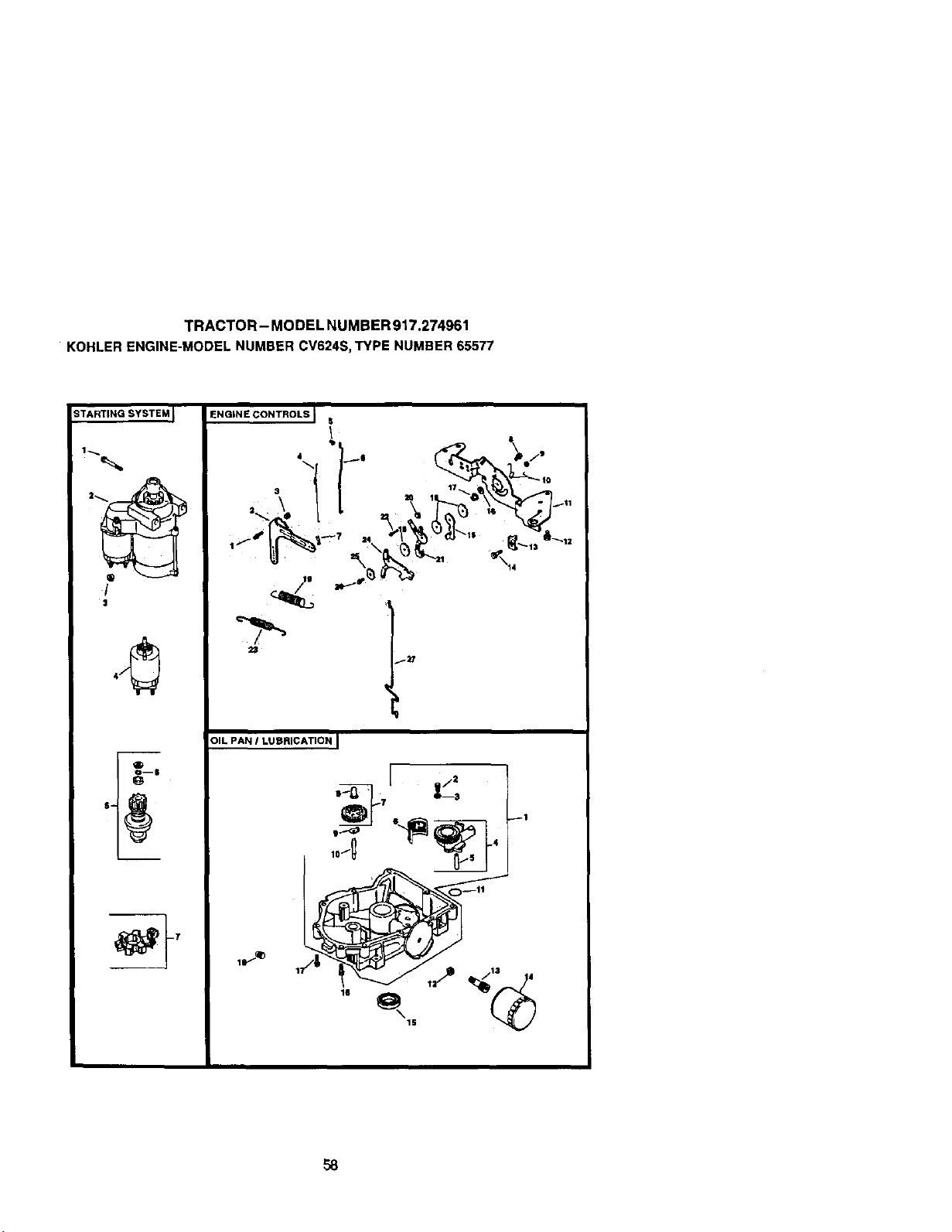
TRACTOR-MODELNUMBER917.274961
KOHLERENGINE-MODELNUMBERCV624S,TYPENUMBER65577
_TARTING SYSTEM I
/
ENGINE CONTROLS J II
\
2S
OIL PAN I LUBRICATION I
1S
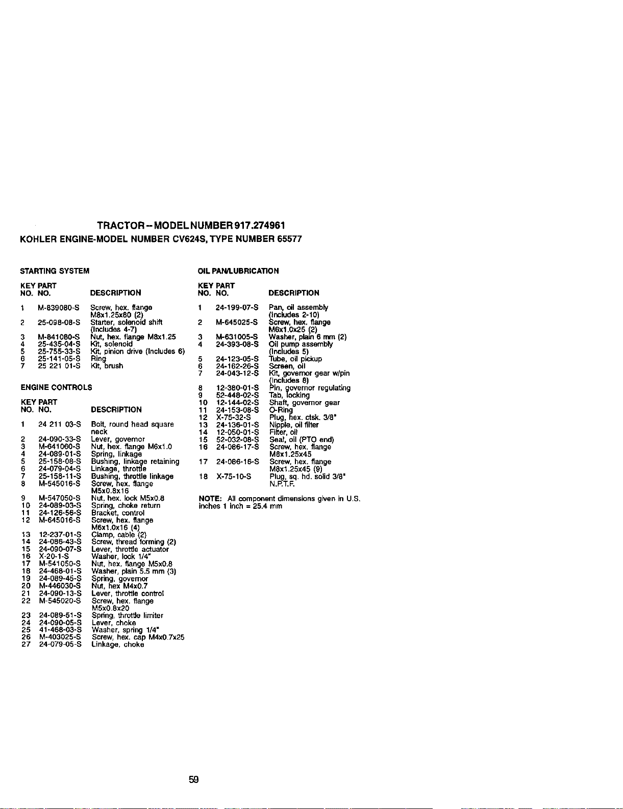
TRACTOR- MODEL NUMBER 917.274961
KOHLERENGINE-MODELNUMBERCV624S,TYPE NUMBER65577
STARTING SYSTEM OIL PAN/1.UBRICATION
KEY PART KEY PART
NO. NO. DESCRIPTION NO. NO. DESCRIPTION
1 M-839080-S Screw. hex. flange
MSx1.25x80 2)
2 25-098-08-S Starter, soenold shift
(Includes 4-7)
3 M-841080-S Nut. hex. f_nge MSxl.25
4 25-435-04-S Kit, solenoid
5 25-755-33-S Kit, pinion drive (Includes 6)
6 25-141-05-S Rin
q
7 25 221 Ot-S Kit.brush
ENGINE CONTROLS
KEY PART
NO. NO. DESCRIPTION
1 24 211 O3-S Bolt. round head square
neck
2 24-090-33-S Lever, governor
3 M-641060-S Nut. hex. flange M6xl.0
4 24-089-01-S Spring, linkage
5 25-158-08-S Bushing, linka_gee retaining
6 24-079-04-S Linkage. throttle
7 25-158-11-S Bushing.. throttle linkage
8 M-545616-S Screw, hex. flange
M5x0.8x16
9 M-547056-S Nut, hex. lock M5xO.8
10 24-089-03-S Spring, choke return
11 24-126-56-S Bracket, control
12 M-645016-S Screw, hex. flange
M6xl.0x16 (4)
13 12-237-01-S Clamp, cabte 2)
14 24-066-43-S Screw, thread forming (2
15 24-090-07-S Lever, throttle actuator
16 X-20-1-S Washer, lock 1/4"
17 M-541050-S Nut, hex. flange MSxO.8
18 24-468-01-S Washer, plain 5.5 mm (3)
19 24-089-45-S Spring, governor
20 M-446030-S Nut, hex M4x0.7
21 24-090-13-S Lever, throttle conVol
22 M-545020-S Screw. hex. flange
M5xO.8x20
23 24-089-51-S Spltng, throttle limiter
24 24-090-05-S Lever, choke
25 41-468-03-S Washer, spring 1/4"
26 M-403025-S Screw, hex. cap M4xO.7x25
27 24-079-05-S Linkage, choke
1 24-199-07-S Pan, oil assembly
(Includes 2-10)
2 M-645025-S Screw, hex. flange
M6x1.Ox25 12)
3 M-631005-S Washer, plato 6 mm (2)
4 24-393-08-S Oil pump assembly
(Includes 5)
5 24-123-05-S Tube, oil pickup
6 24-162-26-S Screen, oil
7 24-043-12-S Kit, governor gear w/pin
(Includes 8)
8 12-380-01-S Pin, gcovernor regulating
9 52-448-02-S Tab, locking
10 12-144-02-S Shaft, governor gear
11 24-153-08-S O-Rin
g
12 X-75-32-S Plug, hex. ctsk. 3/8"
13 24-136-01 -S N'_oFple,oil filter
14 12-050-01-S FiRer, oil
15 52-032-08-S Sea], oil (PTO end)
16 24-086-17-S Screw, hex, flange
M6x1.25x45
17 24-086-16-S Screw, hex. flange
MSx1.25x45 (g)
16 X-75-10-S Plug, sq, hd. solid 3/8"
N.P.T.F.
NOTE: All componentdimensions given in U.S.
inches1 inch = 25.4 mm
59
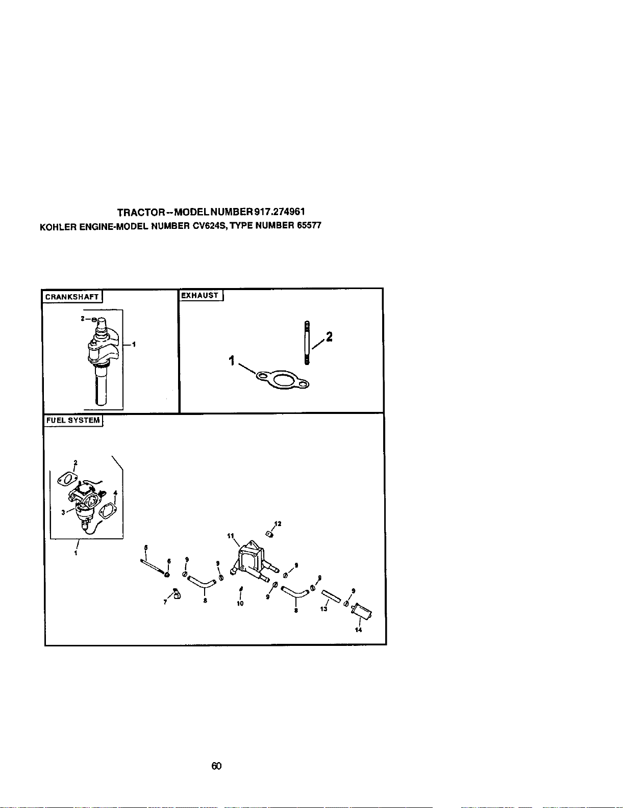
TRACTOR- MODELNUMBER917.274961
KOHLERENGINE-MODELNUMBERCV624S,TYPENUMBER65577
CRANKSHAF'rJ
FUEL SYSTEM I
--t
EXHAUSTJ
4
/
1
S
7 8
8 13
14
6O
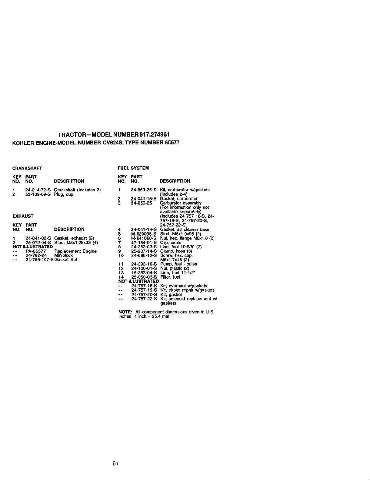
TRACTOR- MODELNUMBER917.274961
KOHLERENGINE-MODELNUMBERCV624S,TYPENUMBER65577
CRANKSHAFT FUEL SYSTEM
KEY PART
NO. NO. DESCRIPTION
1 24-014-72-S Crankshaft (Includes 2)
2 52-139-09-S Plug, cup
EXHAUST
XEY PART
NO. NO. DESCRIPTION
1 24-041-02-S Gasket, exhaust (2)
2 25-O72-04-S Stud, M8x1.25x33 (4)
NOT iLLUSTRATED
-- PA-65577 Replacement Engine
- - 24-782-24 Mioiblock
-- 24-755-107-S Gasket Set
KEY PART
NO. NO. DESCRtPTtON
1 24-853-25-S Kit, carburetor w/gaskets
_ndiudes 2-4)
2 24-041-15-S _asket, carburetor
3 24-053-25 Cafouretor asser_
For informalion only not
available separately)
(Includes 24 757 18-S, 24-
757-19-S, 24-757-20-S,
24-757-22-S_
4 24-041-14-S Gasket, air cleaner base
5 M-629095-S stud, M6x1.0x95 (2)
6 M-64t060-S Nut, hex. flange M6xl 0 (2)
7 47-154-01-S Clip cable
8 24-383-03-S L_e, fuel 10-5/8 (2
9 25-237-14-S Clamp, hose (6)
10 24-086-12-S Screw, hox. cap.
MSxl.7x18 (2)
11 24-393-10-S Pump, fuel - pulse
12 24-100-01-S Nut, plasite (27
13 15-353-04-S Line, fuel 11-1/2"
14 25-050-03-S Filter, fuel
NOT ILLUSTRATED
-÷ 24-757-18-S Kd, overhaul w/gaskets
.* 24-757-19-S Kit, choke repair w/gaskets
-* 24-757-20-S Kit, gasket
.* 24-757-22oS Kit, solenoid replacement w/
gaskets
NOTE: All component dimensions given in U.S.
inches 1 inch = 25.4 mm
61

G2
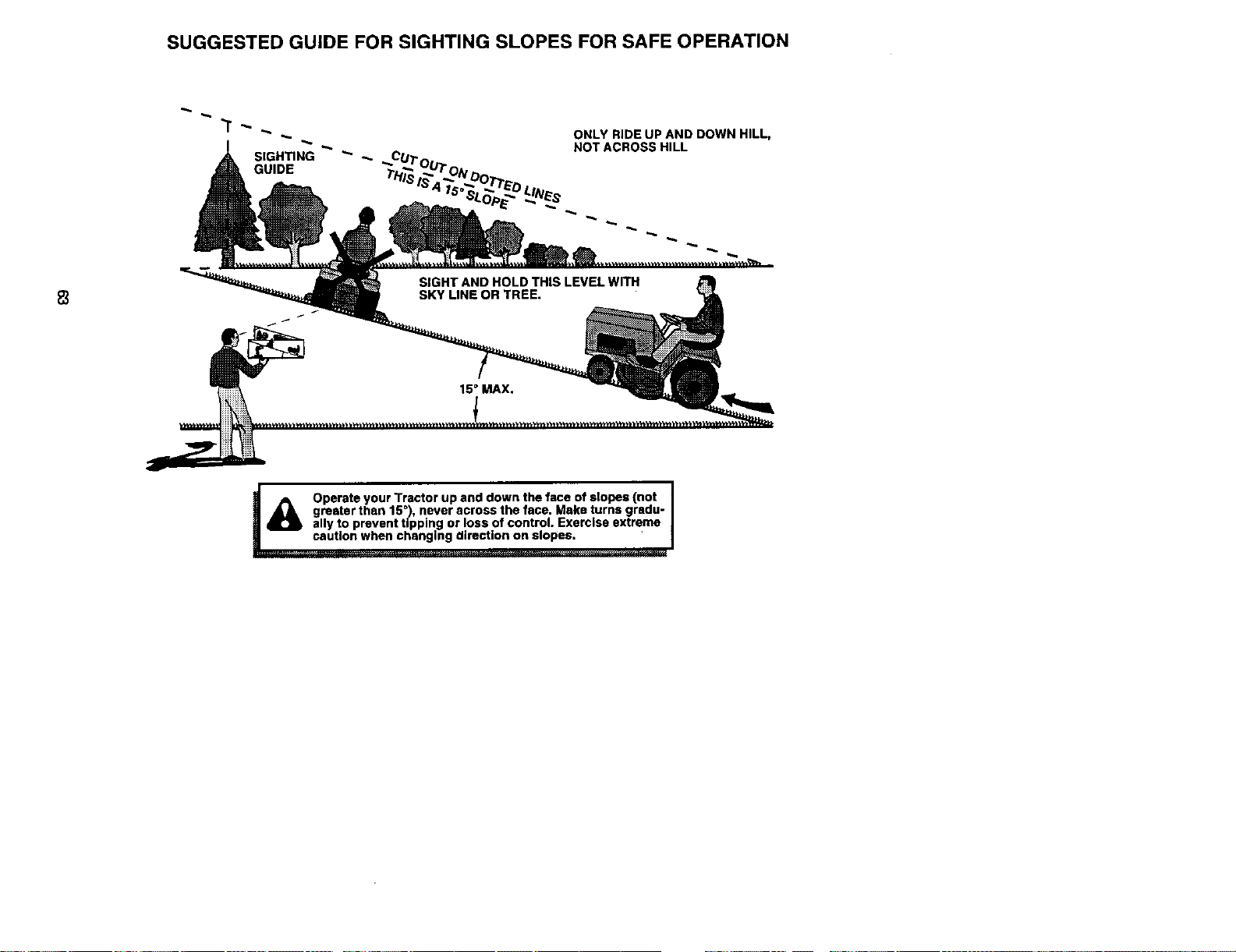
SUGGESTED GUIDE FOR SIGHTING SLOPES FOR SAFE OPERATION
ONLY RIDE UP AND DOWN HILL,
NOT ACROSS HILL
____..o.,_ Operate your Tractor up and down the face of slopes (not
greater than 15 '), never across the face. Make turns gradu-
ally to prevent tipping or loss of control. Exercise extreme

Forrepairofmajorbrand appliancesinyour own home...
nomatterwhomadeit.nomatterwhosoldit]
1-600-4-MY-HOME _ ,a.._al_chyorr_jht
(l-aoo-46g-4663) (u.s.A.a_dCanada)
_Jle_t_aCOIlR W_AI_/,S£_I_.Ca
Forrepairofcarry-inproductsbikevacuums,lawnequipment,and
electronics,callforthenearestSears Partsand RepairCenter.
1-800-488-1222 An,!_ne,_y u right(U.SJ_ody)
wwwJBea,,JLCOrn
Forthereplacementparts,accessoriesand owner'smanuals
that you needtodo-it-yourself,call SearsPartsDIrectS_l
1-800-366-PART 6 a.rn.- 11p.m., 7daysaweek
(1-8_36_7278) _J.,s._.orgy)
_w_
To purchaseorinquireabouta SearsServiceAgreement
or SearsMaintenanceAgreement:
1-600-827-6655 (u.s.A) 1-600-361-6665 (Canada)
7 a.m.- 5p.m..CST,Mort.- Sat. 9a.m.- 8p.m.EST, M- F, 4p.m.Sat.
@ Registered Trademark / _ Trademark / su Service Mark of Seam, Roebuck and Co.
® Mama Reglstrada / TM Marca de F_bdca / su Marca de Servlclo de Sears, Roebuck and Co.
McMarque de commerce / _° Marque ddpos_e de Sears, Roebuck and Co.
178421 3.12.01 RD Printed in U.S.A.


