Loading ...
Loading ...
Loading ...
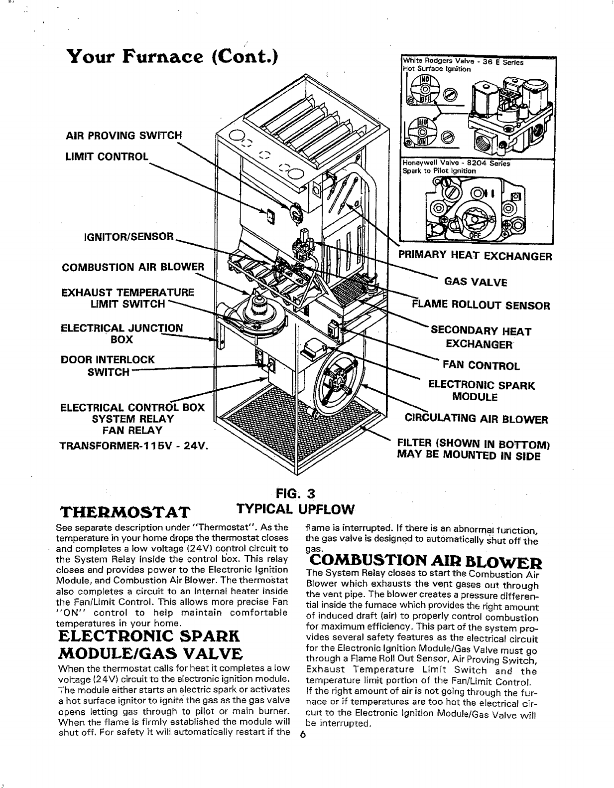
Your Furnace (Cont.)
AIR PROVING SWITCH
LIMIT CONTROL
IGNITOR/SENSOR
COMBUSTION AIR BLOWER
EXHAUST TEMPERATURE
UMIT SWITCH
ELECTRICAL JUNCTION
BOX
DOOR INTERLOCK
ELECTRICAL CONTROL BOX
SYSTEM RELAY
FAN RELAY
TRANSFORMER-115V - 24V.
White Rodgers Valve 3'6 i i
- E Series
Hot Surface ignition
Honeywell Valve _ 8204 Series
Spark to Pilot ignition
PRIMARY HEAT EXCHANGER
GAS VALVE
FLAME ROLLOUT SENSOR
SECONDARY HEAT
EXCHANGER'
FAN CONTROL
ELECTRONIC SPARK
MODULE
CIRCULATING AIR BLOWER
FILTER (SHOWN IN BOTTOM)
MAY BE MOUNTED IN SIDE
THE OSTAT
FIG, 3
TYPICAL UPFLOW
See separate description under "Thermostat". As the
temperature in your home drops the thermostat closes
and completes a tow voltage (24V) control circuit to
the System Relay inside the control I_ox. This relay
closes and provides power to the Electronic Ignition
Module, and Combustion Air Blower. The thermostat
also completes a circuit to an internal heater inside
the Fan/Limit Control. This allows more precise Fan
"ON" control to help maintain comfortable
temperatures in your home.
ELECTRONIC SPARK
MODULE/GAS VALVE
When the thermostat calls for heat it completes a Low
voltage (24V) circuit to the electronic ignition module.
The module either starts an electric spark or activates
a hot surface ignitor to ignite the gas as the gas valve
opens letting gas through to pilot or main burner.
When the flame is firmly established the module will
shut off. For safety it will automatically restart if the
flame is interrupted. !f there is an abnormal function,
the gas valve is designed to automatically shut off the
gas.
COMBUSTION AIR BLOV#ER
The System Relay closes to start the Combustion Air
Blower which exhausts the vent gases out through
the vent pipe. The blower creates a pressure differen-
tial inside the furnace which provides the right amount
of induced draft (air) to properly control combustion
for maximum efficiency. This part of the system pro-
vides several safety features as the electrical circuit
for the Electronic Ignition Module/Gas Valve must go
through a Flame Rol! Out Sensor, Air Proving Switch,
Exhaust Temperature Limit Switch and the
temperature limit portion of the Fan/Limit Control.
If the right amount of air is not going through the fur-
nace or if temperatures are too hot the electrical cir-
cu=t to the Electronic Ignition Module/Gas Valve will
be interrupted.
6
Loading ...
Loading ...
Loading ...