Loading ...
Loading ...
Loading ...
English
8
Fig. C
15
16
17
One-Touch
TM
Two-Touch
TM
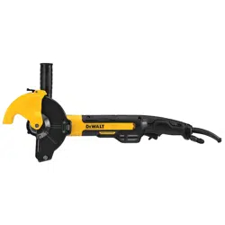
setting guard Adjustment Options
To adjust the guard release lever
15
for desired
adjustmentoption:
1. Remove screw
16
using a T20bit.
2. Remove the guard release lever taking note of the
spring position. Choose the end of the lever for the
desired adjustment option. One-touch will use the
slanted end of the lever
15
to engage the alignment
holes
13
on the guard collar. Two-touch will use the
squaredend to engage the alignment holes
13
on the
guardcollar.
3. Replace the lever, positioning the chosen end under the
spring
17
. Ensure the lever is in proper contact with
thespring.
4. Replace screw and torque to 2.0-3.0N-m. Ensure proper
installation with spring return function by depressing
guard release lever
15
.
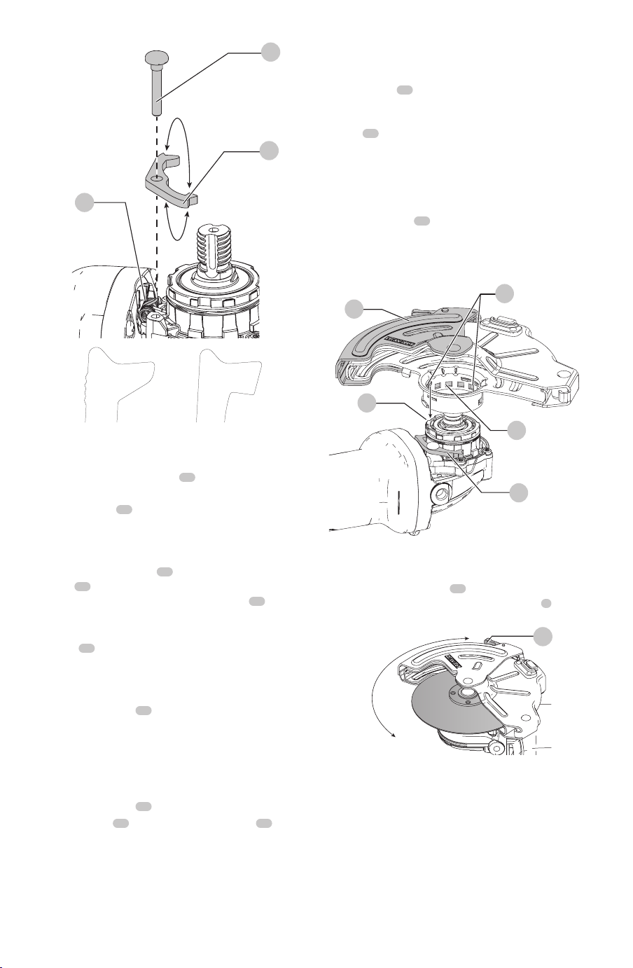
Mounting guard (Fig. D)
CAUTION: Prior to mounting guard, ensure the screw,
lever, and spring are fitted correctly before mounting
theguard.
1. With the spindle facing the operator, press and hold the
guard release lever
15
.
2. Align the lugs
12
on the guard with the slots
18
on
the gearcasecover.
3. Push the guard down until the guard lugs engage
and rotate them in the groove on the gear case cover.
Release the guard releaselever.
4. To position the guard:
One-touch
TM
: Rotate the guard clockwise into the
desired working position. Press and hold the guard
release lever
15
to rotate the guard in the counter-
clockwisedirection.
Two-touch
TM
: Press and hold the guard release
lever
15
. Rotate the guard clockwise or counter-
clockwise into the desired working position.
nOTE: The guard body should be positioned between
the spindle and the operator to provide maximum
operatorprotection.
The guard release lever should snap into one of the
alignment holes
13
on the guard collar. This ensures
that the guard issecure.
5. To remove the guard, follow steps 1–3 of these
instructions inreverse.
11
Fig. D
12
13
15
18
To Adjust the heavy-Duty Cut-off guard (Fig. D, E)
When application allows and/or greater guard coverage
is preferred, the outer guard
11
can be adjusted closed
by pressing the guard opening adjustment lever
9
and
rotating the outer guard to the desiredposition.
Fig. E
9
Gear Case Orientation
DWE46266N is sold with the spindle-side of the gear case
facing to the left relative to the switch or trigger facing
down. This position is ideal for cutting applications. The
gear case can be repositioned to a different orientation if
preferred by the user.
CAUTION: Do not reposition the gear case when
using the stock adjustable cut-off guard.
Loading ...
Loading ...
Loading ...