Mobile DVR and NVR Series Quick Start Guide
V1.0.1

i
Table of Contents
1 INSTALLATION AND CONNECTIONS .................................................... 1
1.1 Device Cable Connection ....................................................................................................... 1
1.1.1 Power Cable Connection ................................................................................................... 1
1.1.2 Alarm Connection ............................................................................................................... 3
1.1.3 Isolating Installation ............................................................................................................ 5
1.2 Install Device Antenna ............................................................................................................ 7
1.2.1 Mobile Network Antenna.................................................................................................... 7
1.2.2 GPS Antenna Installation .................................................................................................. 8
2 BOOT UP SHUT DOWN ........................................................................ 11
3 DEVICE INITIALIZATION ....................................................................... 12
4 LOGIN .................................................................................................... 15
5 OPERATIONS ........................................................................................ 17
5.1 Adjust Device Antenna ......................................................................................................... 17
5.1.1 Adjust Mobile Network Antenna ..................................................................................... 17
5.1.2 Adjust GPS Antenna ........................................................................................................ 17
5.2 Local Alarm ............................................................................................................................. 18
5.3 Auto Register ......................................................................................................................... 19
5.4 Set Plate Number .................................................................................................................. 20
5.5 Reset Password ..................................................................................................................... 21

ii
6 FAQ ........................................................................................................ 26
6.1 About Boot up ........................................................................................................................ 26
6.2 No Record File ....................................................................................................................... 26
6.3 Positioning Module ................................................................................................................ 26
6.4 Network ................................................................................................................................... 27

iii
Welcome
Thank you for purchasing our DVR/NVR!
This quick start guide is designed to be a reference tool for the installation and operation
of your system.
Before installation and operation please read the following safeguards and warnings
carefully!
Please keep it for future reference!

iv
Important Safeguards and Warnings
1.Electrical safety
All installation and operation here should conform to your local electrical safety codes.
The product must be grounded to reduce the risk of electric shock.
We assume no liability or responsibility for all the fires or electrical shock caused by
improper handling or installation.
2.Transportation security
Heavy stress, violent vibration or water splash are not allowed during transportation,
storage and installation.
3.Installation
Keep upwards. Handle with care.
Do not apply power to the device before completing installation.
Do not place objects on the device.
4.Qualified engineers needed
All the examination and repair work should be done by the qualified service engineers.
We are not liable for any problems caused by unauthorized modifications or attempted
repair.
5.Environment
The device should be installed in a cool, dry place away from direct sunlight, inflammable,
explosive substances and etc.
6. Accessories
Be sure to use all the accessories recommended by manufacturer.
Before installation, please open the package and check all the components are included.
Contact your local retailer ASAP if something is broken in your package.
Safety Instruction
Icon
Note
DANGER
Indicates a hazard with a high level of risk, which if not avoided, will
result in death or serious injury.
CAUTION
Indicates a potentially hazardous situation, which if not avoided,
could result in device damage, data loss, performance degradation,
or unexpected results.
Tips
It is intended to help you to fix a problem or save your time.

v
Icon
Note
Note
Provides additional information to emphasize or supplement
important points of the main text.
Privacy Protection Notice
As the device user or data controller, you might collect personal data of others'
such as face, fingerprints, car plate number, Email address, phone number, GPS
and so on. You need to be in compliance with the local privacy protection laws
and regulations to protect the legitimate rights and interests of other people by
implementing measures include but not limited to: providing clear and visible
identification to inform data subject the existence of surveillance area and
providing related contact.
About the Manual
The Manual is for reference only. If there is inconsistency between the
Manual and the actual product, the actual product shall prevail.
We are not liable for any loss caused by the operations that do not comply
with the Manual.
The Manual would be updated according to the latest laws and regulations
of related regions. For detailed information, see the paper User's Manual,
CD-ROM, QR code or our official website. If there is inconsistency between
paper User's Manual and the electronic version, the electronic version shall
prevail.
All the designs and software are subject to change without prior written
notice. The product updates might cause some differences between the
actual product and the Manual. Please contact the customer service for the
latest program and supplementary documentation.
There still might be deviation in technical data, functions and operations
description, or errors in print. If there is any doubt or dispute, please refer to
our final explanation.
Upgrade the reader software or try other mainstream reader software if the
Guide (in PDF format) cannot be opened.
All trademarks, registered trademarks and the company names in the
Manual are the properties of their respective owners.
Please visit our website, contact the supplier or customer service if there is
any problem occurred when using the device.
If there is any uncertainty or controversy, please refer to our final
explanation.

1
1 Installation and Connections
1.1 Device Cable Connection
1.1.1 Power Cable Connection
Caution
Before connect the power cable, make sure the input voltage ranges from DC 6V to DC
36V. The improper voltage may result in device damage.
Make sure the positive end and negative end connection is right. The improper cable
connection may result in device damage.
The cable diameter shall be 1.0mm² or higher. Always use the cable brand recommended
by the device manufacturer.
Close the power main on-off button on the vehicle and make sure the vehicle key is on the
OFF position before the power cable connection.
1.1.1.1 About Power Cable
The device power cable has three types. See Figure 1-1.
Connect one end of the power cable to the device power port (The port on the left) or just pull
the power cable through the device, connect the other end of the power cable to the storage
battery (The port on the right). Among which, red cable with the fuse is the power positive end
(Live), black cable is the ground (GND), orange cable is the ACC signal (use key to start.)
Note
Some series products support this kind of cable connection. Refer to the product user’s manual
for detailed information.
Figure 1-1
1.1.1.2 Get the Power Main On-Off Button Connection Mode
To properly connect the cable, please get to know the power main on-off connection mode. That
is to say, you need to know the power main on-off button is at the positive end or at the negative
end.
Contact the vehicle manufacturer to get the power main on-off connection mode.

2
Use multimeter to check: Turn the power main on-off button off and check the voltage
between the vehicle and the storage battery. If the voltage is 12V/24V, that is to say, the
main on-off button has disconnected the positive end. If the voltage is 0V, that is to say, the
main on-off button has disconnected the negative end.
Use your eyes to check: Check the power on-off button near the storage battery is
connecting to the positive end or the negative end.
1.1.1.3 Connection
The mobile DVR/NVR shall connect to the ground cable, ACC signal, and constant electric.
Step 1 Turn the vehicle main power on-off button to the ON, and the vehicle key is on the OFF.
If the multimeter can check the voltage, it is the vehicle constant electric. Usually the
large vehicle is DC 24V, the small vehicle is DC 12V. It may vary depending on
different situations.
Step 2 Put the vehicle key on the ACC status or on the ON and then check vehicle ACC
signal. Use the multimeter to check the DC voltage on fuse voltage. When the
multimeter can check the voltage, remove the vehicle key. It is the vehicle ACC signal
if the voltage becomes 0V.
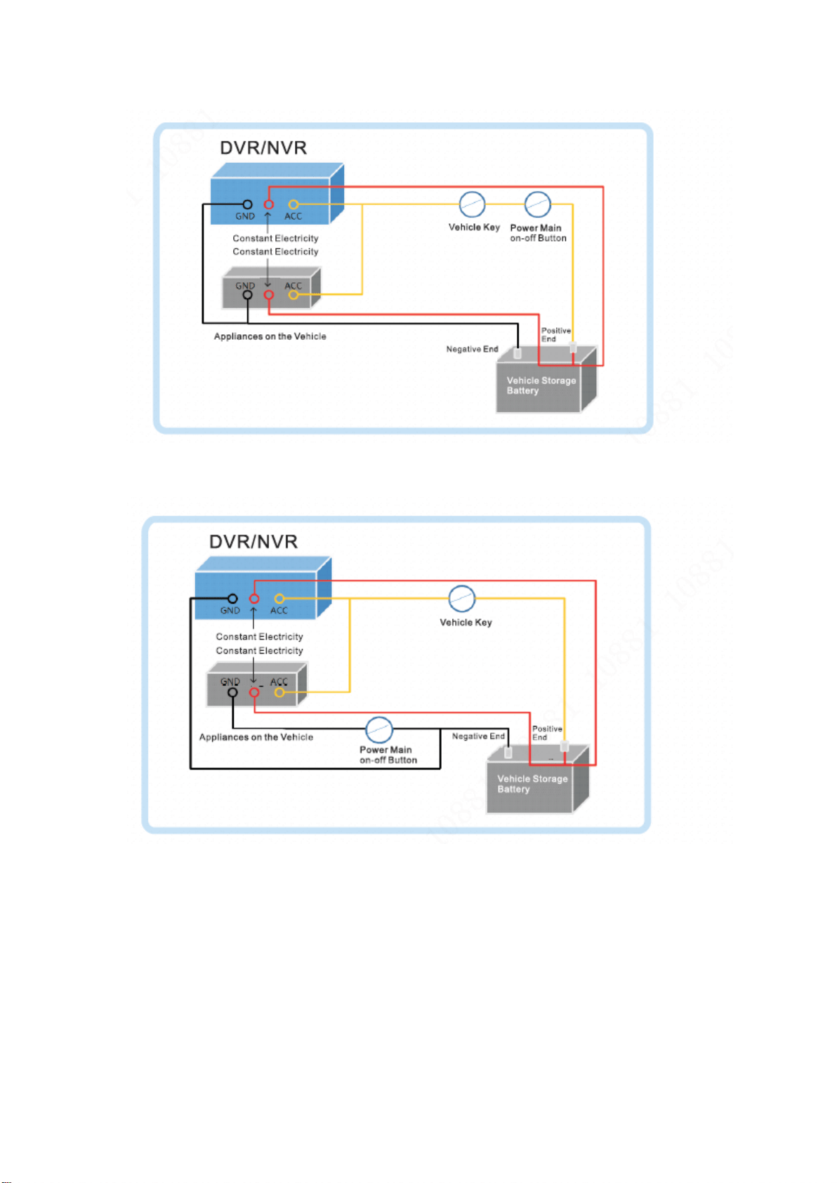
Step 3 Close the vehicle power main on-off button, and the vehicle key is on the OFF.
Step 4 Connect power cable according to vehicle power main on-off mode. See Figure 1-2
and Figure 1-3.
Caution
Before connecting the power cable, please select proper fuse. For the constant electric DC
24V vehicle, the recommended fuse is 7.5A. For the constant electric DC 12V vehicle, the
recommended fuse is 20A.
For the power positive end and negative end, please use necessary security measures
such as installing protective tube.
If vehicle power main on-off button is on the negative end, please isolate the installation.
Refer to chapter 1.1.1.3 for detailed information.
3
Figure 1-2
Figure 1-3
1.1.2 Alarm Connection
Refer to the following contents for alarm connection information if you want to view emergency
alarm, left-turn, right-turn, reverse, brake, open/close door alarm signal.
1.1.2.1 Alarm Input Mode
Alarm input mode supports high level/low level.
The low level supports DC 0V-DC 1.5V.
The high level supports DC 4V-DC 36V.
4
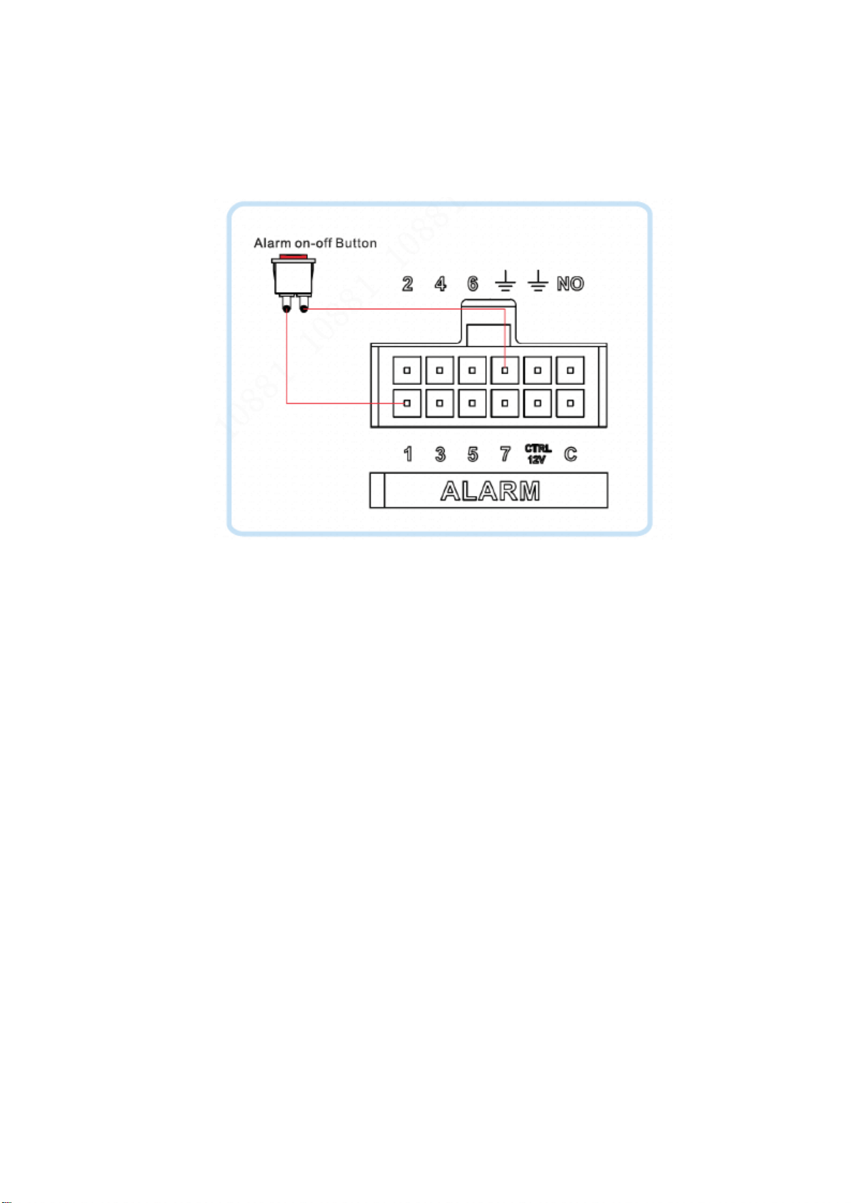
1.1.2.2 Connecting Emergency Alarm
The emergency button shall connect to the alarm port. See Figure 1-4. The trigger mode shall
be low level, the device type is NO. Refer to chapter 5.2 for detailed information.
Figure 1-4
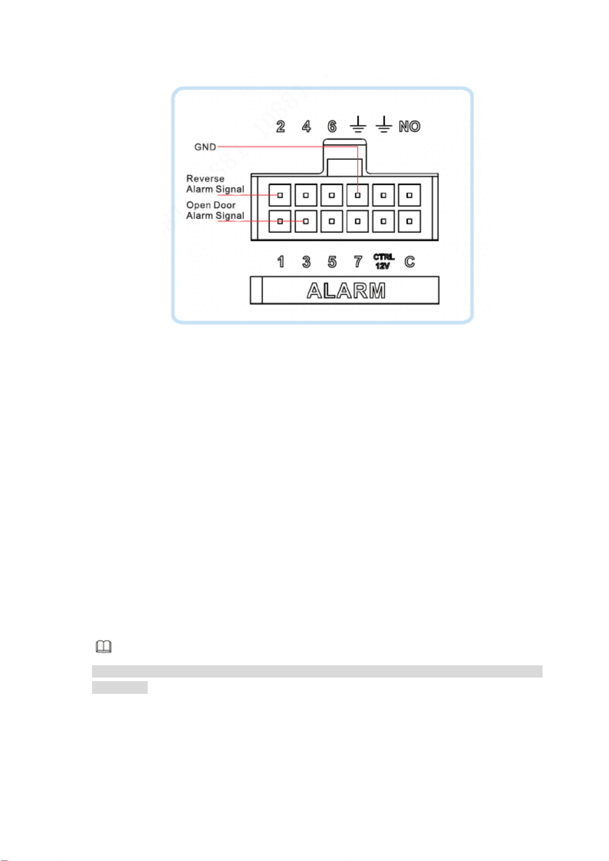
1.1.2.3 Connect to other alarm types
Here we use reverse and vehicle signal as an example to introduce other alarm types.
The reverse signal and vehicle door signal can be used as alarm input signal to connect to the
device.
Connecting reverse alarm signal
For the vehicle of reverse indicator light (R): Connecting to the reverse indicator light.
The cable of +12V or the +24V is the reverse signal cable when the vehicle is in the
reverse mode.
For the vehicle of no reverse indicator light: Connect to the reverse on-off button from
the gearbox. The cable of +12V or the +24V is the reverse signal cable when the
vehicle is in the reverse mode.
Connecting vehicle door alarm signal
For the vehicle of door status indicator light: Connecting to the door status indicator
light. The cable of +12V or the +24V is the door status cable when the vehicle door is
open.
For the vehicle of no door status indicator light: Connect to vehicle door on-off button.
The signal is the high level or the low level pulse signal.
Refer to Figure 1-5 for reverse and door signal alarm connection information. The reverse is
corresponding to alarm input 2, vehicle door is corresponding to alarm input 3. The trigger mode
of reverse and door signal alarm is high level, device type is NO. Refer to chapter 5.2 for
detailed information.
5
Figure 1-5
1.1.3 Isolating Installation
For the power main on-off button is on the negative end of the storage battery, the appliances
on the vehicle can use the DVR/NVR case, vehicle body or the storage battery to generate a
circuit if the vehicle power main on-off button is OFF. It may result in the following problems.
Please isolate the vehicle installation.
When there are appliances of high power consumption, the negative end temperature
becomes hot and then burn down.
The appliances on the vehicle cannot be turned off.
The DVR/NVR on the vehicle cannot be shut down.
The isolation here refers to isolate the whole system case and vehicle body. It mainly refers to
isolate the device and the camera.
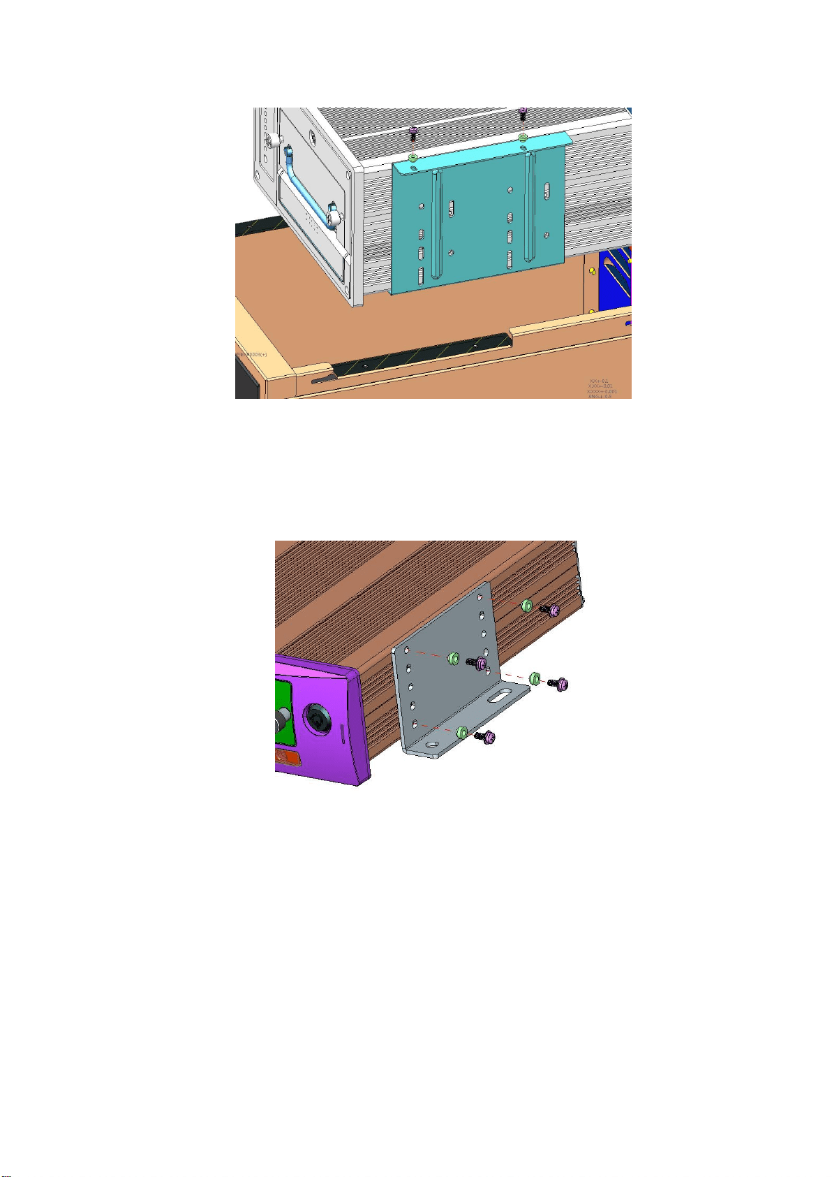
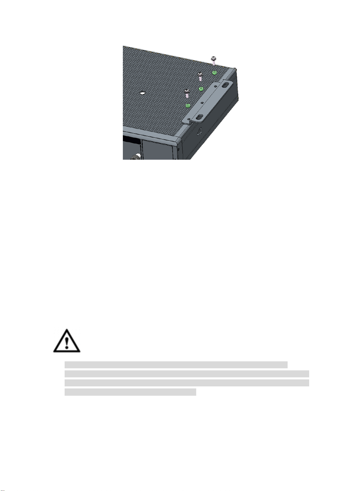
1.1.3.1 Isolating the Installation Device
The installation device isolation includes case isolation installation and DVR/NVR isolation
installation. Please select one type according to your actual situation.
1.1.3.1.1 Isolate Installation Rack
Use the fastening screws to secure the isolation pad on the case. See Figure 1-6.
Note
Refer to Figure 1-6 for recommended case information. The isolation pad is the default
accessory.
7
Figure 1-8
1.1.3.2 Isolating Camera
For our own camera brand, the case and the negative end of the power has been isolated.
There is no need to isolate the camera. If you are using the camera from the third party, please
check it needs to be isolated or not.
Step 1 Check whether it needs to isolate the camera or not.
Use multimeter to check there is current between camera case and the power
negative end or not. If there is current, please isolate the camera.
Step 2 How to isolate the camera.
Install on the insulating decorative pane. The decorative pane is on the vehicle.
Install camera on the insulation pane and then secure the insulation pane on the
vehicle.
1.2 Install Device Antenna
It is to connect device to the network so that to pin point vehicle position.
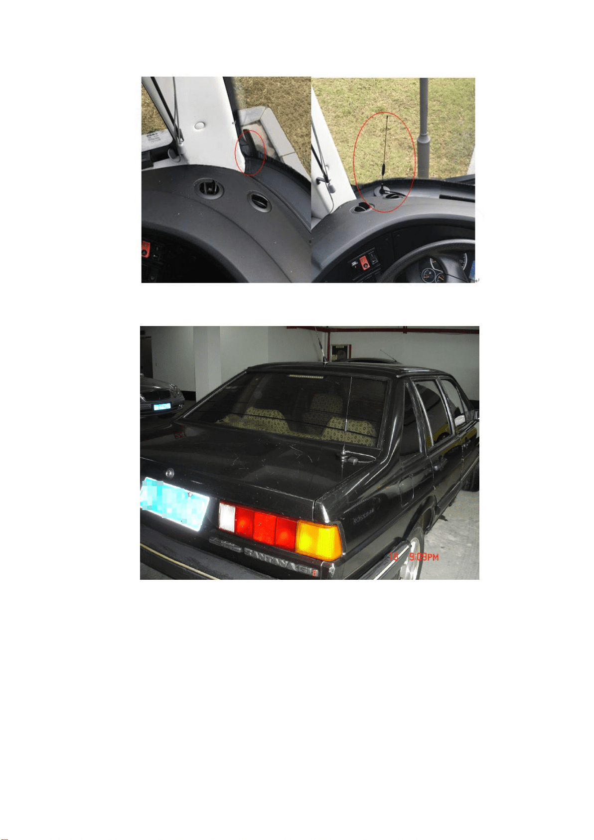
1.2.1 Mobile Network Antenna
Caution
If you want to paste the antenna, make sure the bottom material cannot be metal.
For the antenna of large chuck, please make sure it is straight up and is sucking on the
metal. In some special circumstance, if the sucking material is not the metal, you can use
two-sided 3M paste or using the glue to secure.
Refer to Figure 1-9 to install the mobile antenna in the vehicle. For the big flat antenna or the
antenna of large chuck, please make it is straight up near the window shield (on the instrument
pane, at the bottom of the window shield). Or you can install inside of the instrument pane.
Refer to Figure 1-10 to install the mobile antenna outside of the vehicle. The antenna of large
chuck is at the top of the vehicle or the trunk.
8
Figure 1-9
Figure 1-10
1.2.2 GPS Antenna Installation
Right now, the popular positioning module includes GPS, Beidou, GLONASS and etc. The
corresponding antenna includes GPS antenna, Beidou antenna, and GLONASS antenna.
The following contents are based on the GPS antenna. For the other types, the installation
steps are generally the same.
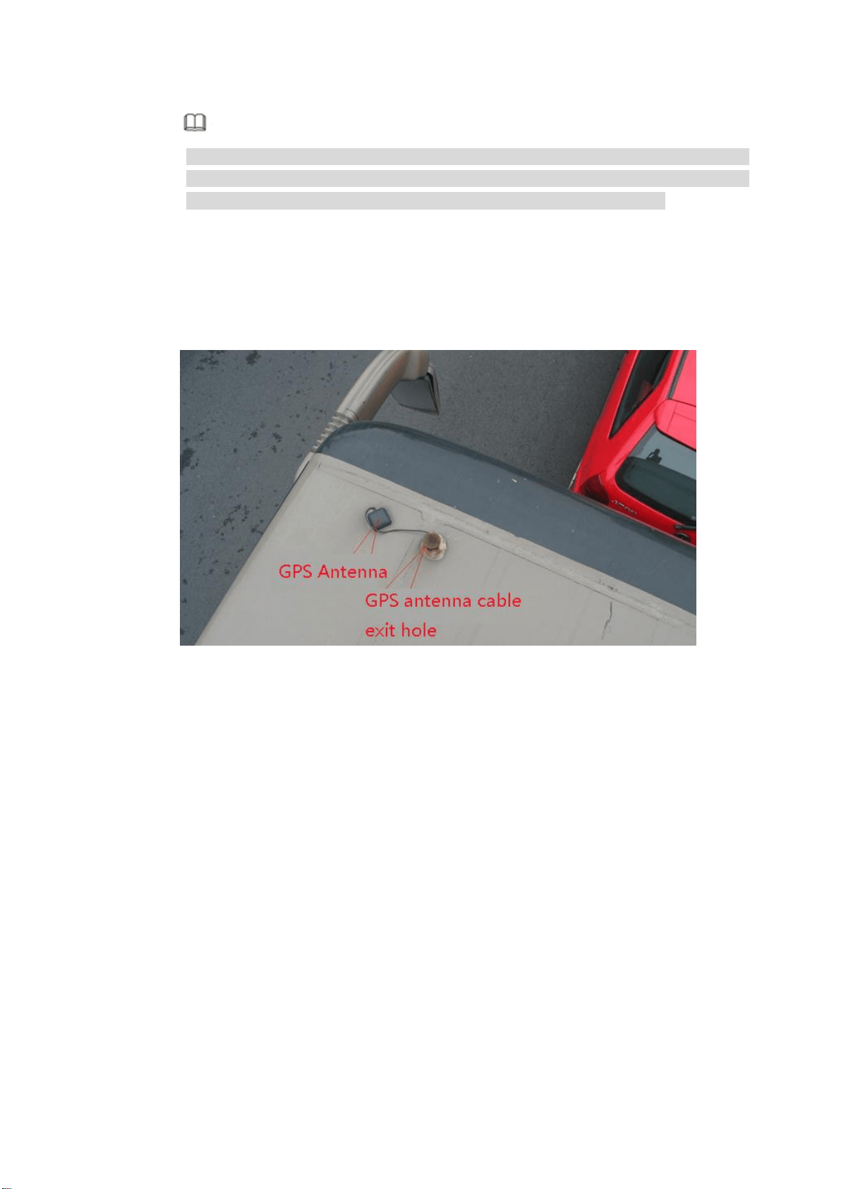
1.2.2.1 Outside Installation
Step 1 Install the GPS antenna at the left front of the top. See Figure 1-11.
The GPS antenna is magnetic and can be installed on the top cover. To guarantee
reliability, you can paste glue around the antenna.
9
Note
To guarantee positioning sensitivity and accuracy, make sure there are no appliances
of high power consumption, electronic interference source (fan or air-conditioning
compressor) or obstacle within 1 meter radius around the GPS antenna.
Step 2 Pull GPS antenna through the antenna hole at the top of the vehicle to the inside of the
vehicle, and connect the GPS antenna.
The GPS antenna cable exit hole shall meet the following requirements:
The inner hole cannot be more than Ø10mm.
Waterproof.
Easy to replace and maintain the antenna.
Figure 1-11
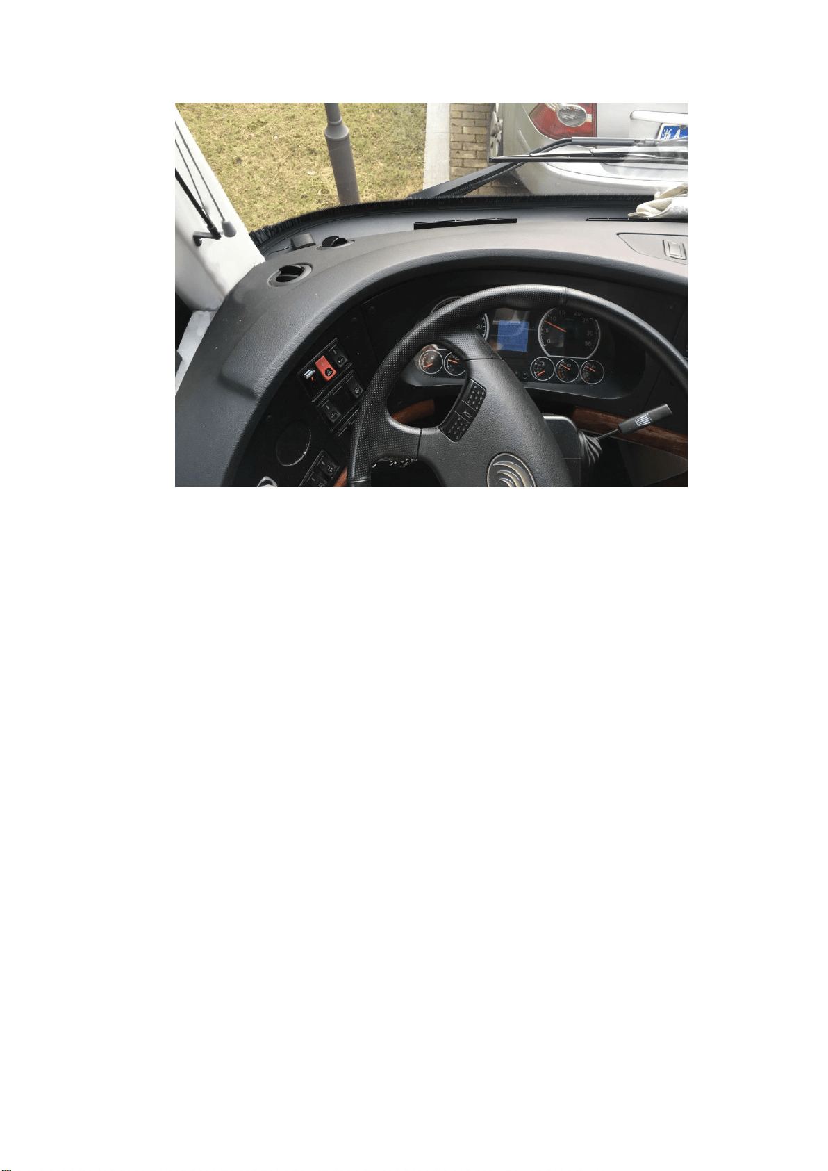
1.2.2.2 Inside Installation
If it is difficult to do the waterproof job or the cabling, you can install the antenna inside of the
vehicle.
Please select the installation position. Usually we recommend the antenna is at the instrument
pane near the window shield and the GPS antenna is facing to the air to enhance signal
intensity. See Figure 1-12.
10
Figure 1-12

11
2 Boot up Shut Down
Different series products may have different boot up/shut down operations. Please refer to the
user’s manual for detailed information.
Boot up: Turn the device key to the and the vehicle key to the ACC. The power
indicator light becomes on and the DVR/NVR boots up. The boot up process may take a
little bit long. The device displays initialization interface after it first boots up.
Shut down: When vehicle ACC is off, the device automatically shuts down or shuts down
according to the settings on the auto maintain interface.
12
3 Device Initialization
If it is your first time to use the device or device has restored factory default settings, please set
a login password of admin (system default user). You can select to use unlock pattern to login
or not at your own choosing.
Here we use local interface to continue. Refer to User’s manual for detailed WEB information.
Note
For your device safety, please keep your login password of admin well after the initialization
steps, and change the password regularly.
Preparations
Device has connected to the monitor and the mouse.
Please follow the steps listed below.
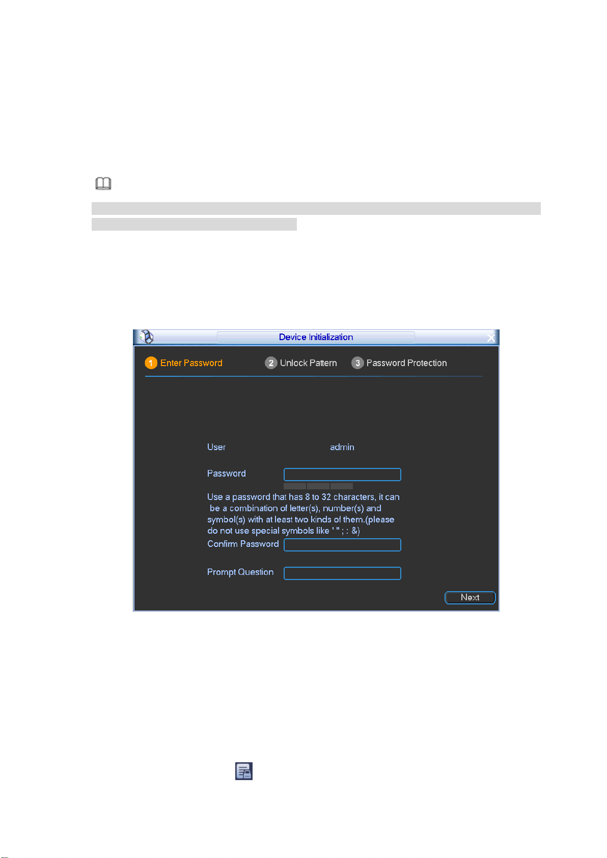
Step 1 Boot up DVR/NVR.
Device displays device initialization interface. See Figure 3-1.
Figure 3-1
Step 2 Set login password of admin.
User name: The default user name is admin.
Password/confirm password: The password ranges from 8 to 32 digitals. It can
contain letters, numbers and special characters (excluding “'”,“"”,“;”,“:”,
“ &” ) . The password shall contain at least two categories. Usually we
recommend the strong password.
Prompt question: If you set the prompt question here. On the login interface, move
your mouse on , device can display the corresponding prompt question for

13
you to remind the password.
WARNING
STRONG PASSWORD RECOMMENDED-For your device own safety, please
create a strong password of your own choosing. We also recommend you
change your password periodically especially in the high security system.
Step 3 Click Next, device goes to the following interface. See Figure 3-2.
Figure 3-2
Step 4 Set unlock pattern.
After set unlock pattern, device goes to password protection interrface. See Figure
3-3.
Note
Device adopts unlock pattern to login by default if you have set pattern here. If
there is no unlock pattern, please input the password to login.
Click Skip if there is no need to set unlock pattern.
14
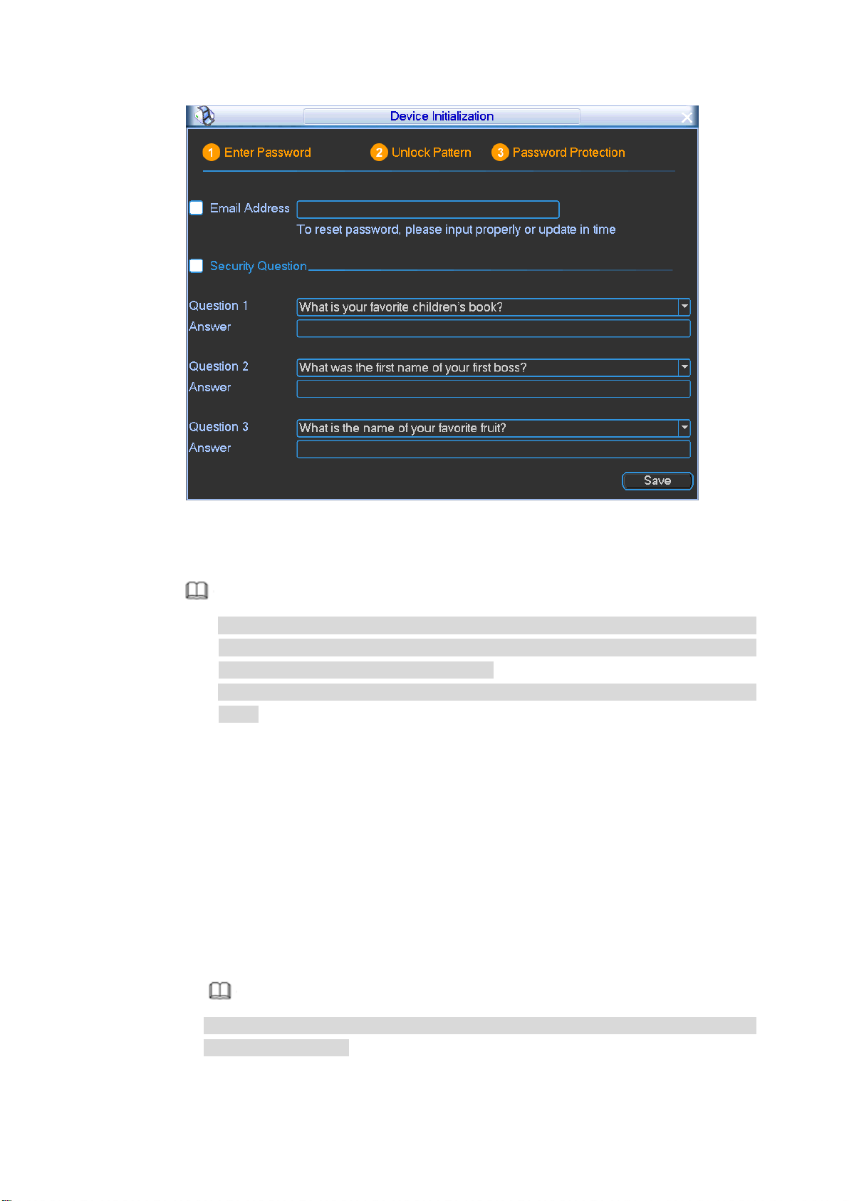
Figure 3-3
Step 5 Set security questions.
Note
After setting the security questions here, you can use the email you input here or
answer the security questions to reset admin password. Refer to chapter 5.5
Reset password for detailed information.
Cancel the email or security questions box and then click Next button to skip this
step.
Email: Input an email address for reset password purpose. In case you forgot
password in the future, input the security code you got on the assigned email to
reset the password of admin. If you have not input email here or you need to
update the email information, please go to the main
menu->Setting->System->Account->Modify user to set. Refer to user’s manual
for detailed information.
Security question: Set security questions and corresponding answers. Properly
answer the questions to reset admin password. In case you have not input
security question here or you need to update the security question information,
please go to the main menu->Setting->System->Account->Security question to
set. Refer to user’s manual for detailed information.
Note
If you want to reset password by answering security questions, please go to the
local menu interface.
Step 6 Click OK to complete the device initialization setup.
15
4 Login
After you initialized device, you can set or operate the device. Here we use local interface to
continue. Refer to User’s manual for detailed WEB information.
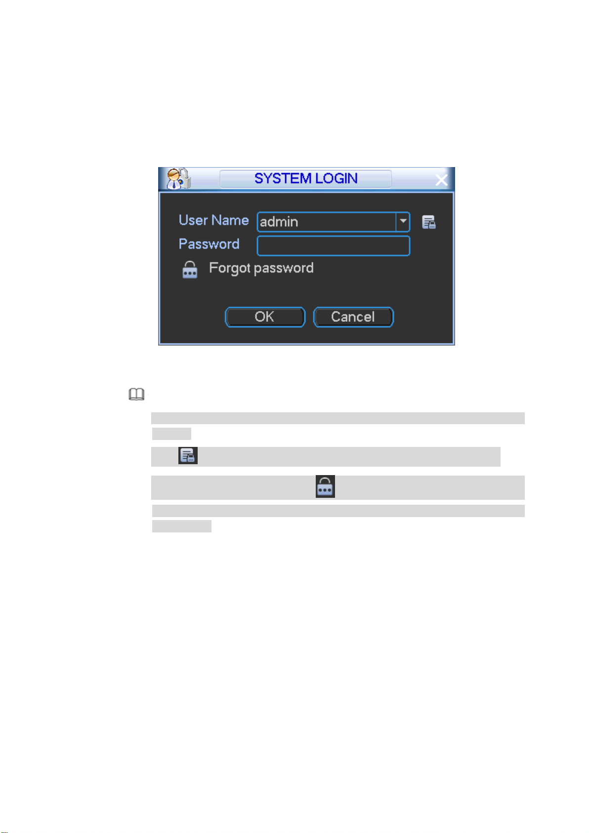
Step 1 On the preview interface, right click mouse and select Main menu,
Enter login interface. See Figure 4-1.
Figure 4-1
Note
If you have set unlock pattern, device goes to unlock pattern interface to login by
default.
Click to view the prompt information to help you remember password.
In case you forgot password, click to answer security questions or use the
email to reset password. Refer to chapter 5.5 Reset password for detailed
information.
Step 2 The default user is admin, and then input the corresponding password (the password
you set during initialization process).
Step 3 Click OK.
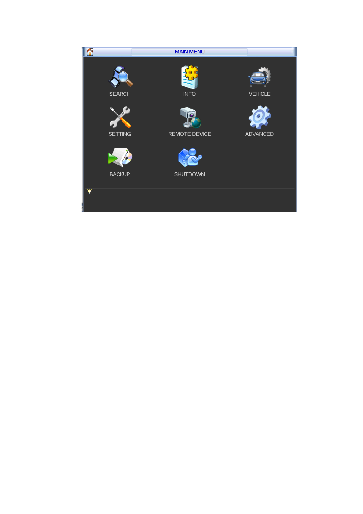
Enter main menu interface. See Figure 4-2.
16
Figure 4-2
17
5 Operations
Here we use local interface to continue. Refer to User’s manual for detailed WEB information.
5.1 Adjust Device Antenna
After install the device antenna, please check antenna installation effect. If the result is not ideal
please adjust the antenna to get better signal intensity.
5.1.1 Adjust Mobile Network Antenna
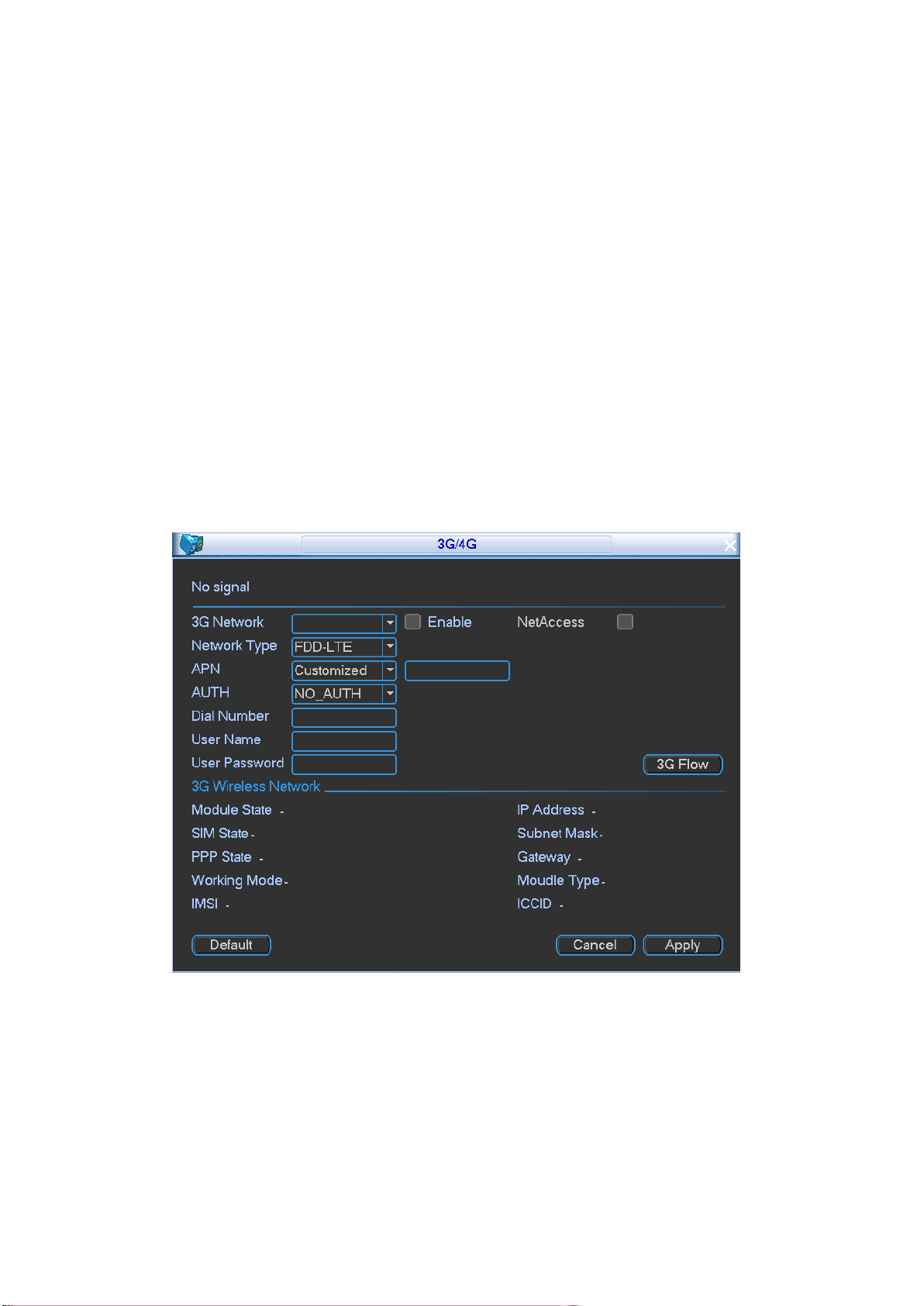
Go to the 3G/4G interface to check antenna effect. Refer to the signal intensity to adjust
antenna. Usually the signal intensity shall be 4 grids or higher.
Step 1 On the local menu, from Vehicle->3G/4G,
Enter 3G/4G interface. See Figure 5-1.
Step 2 Check the box to enable 3G/4G function and set 3G/4G parameters.
Refer to the user’s manual, VPN administrator or the 3G/4G operator to set.
Step 3 Click OK button.
The dial operation is successful if there is IP address on the IP address column.
Figure 5-1
5.1.2 Adjust GPS Antenna
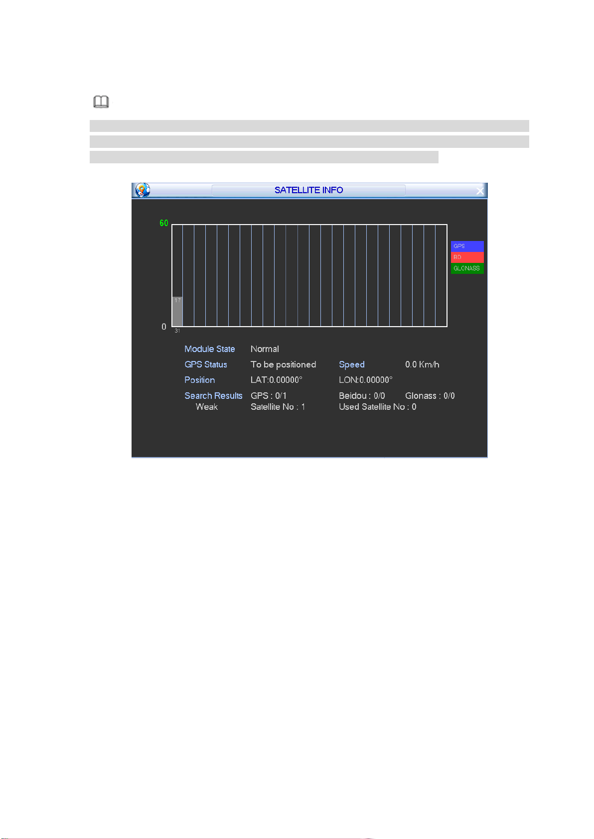
Close all appliances (such as air-conditioning, heater, light and etc.) on the vehicle and the
open all applications to check the corresponding satellite intensity and positioning speed.
Refer to the following requirements to install the antenna.
On the open environment, the positioning satellites amount shall be more than 10 and the
positioning satellite signal shall be more than 40.
18
The detected satellites intensity is close after close/open all appliances.
Note
If the signal is clearly weak after open all appliances, that is to say, the appliances on the
vehicle may interfere the antenna. Please install the antenna again. If there is still interference
after install the antenna for several times, please use the shield enclosure.
On the main menu, from Info->Satellite, enter satellite information interface. See Figure 5-2.
Figure 5-2
5.2 Local Alarm
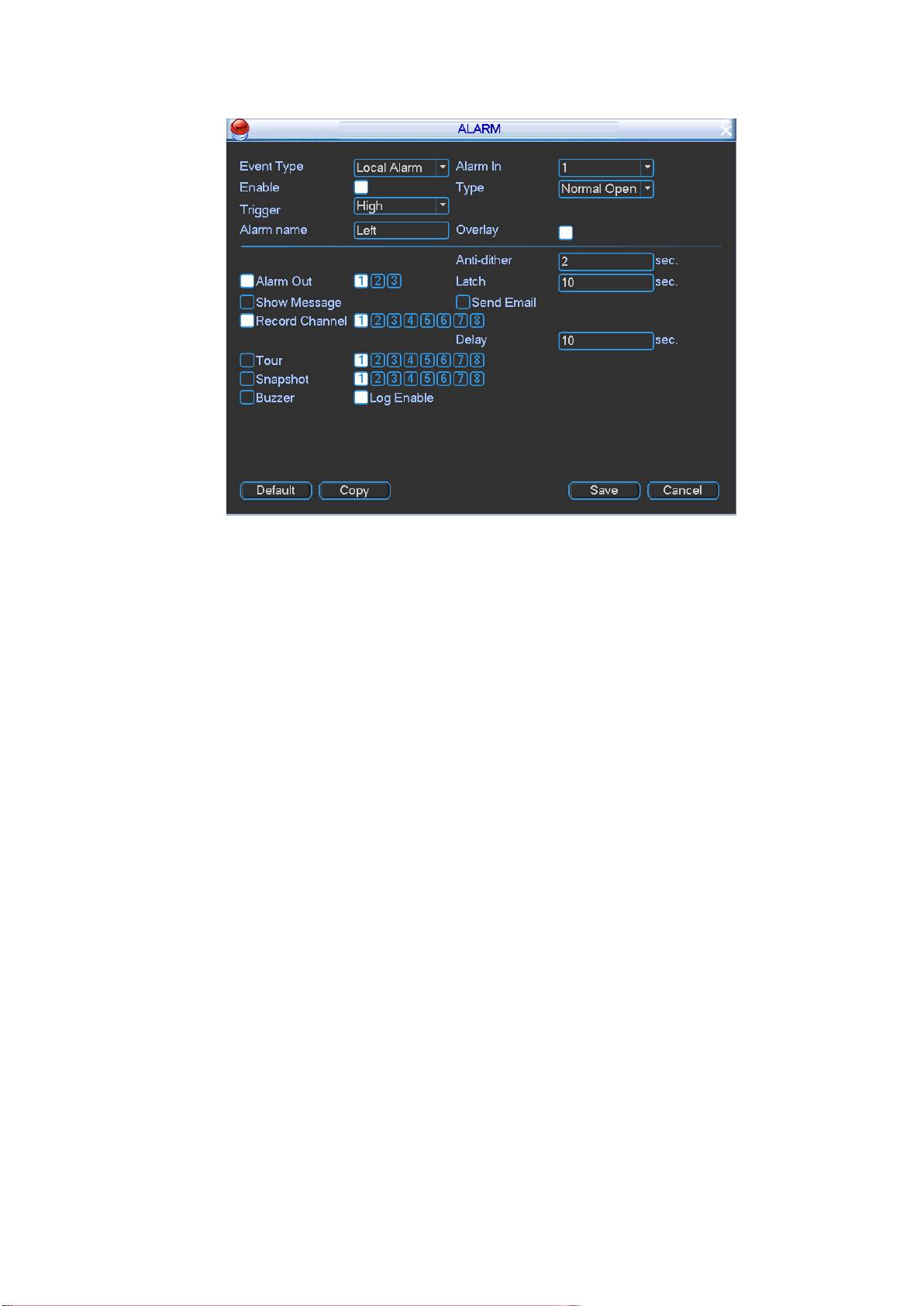
It is to set local alarm trigger mode and corresponding activations. When there is a local alarm,
the device can generate an alarm and trigger the corresponding actions.
Step 1 On the main menu, from Setting->Alarm,
Enter Alarm interface. See Figure 5-3.
19
Figure 5-3
Step 2 Set event type as local alarm.
Step 3 Select alarm input channel and check the box to enable this function.
Step 4 Set trigger mode and device type. And set corresponding activation actions.
Type: Normal open or normal close. This item is for local alarm only.
The normal open means the alarm signal is usually disconnect, system can
generate an alarm when the alarm signal closed.
The normal close means the alarm signal is usually connect, system can
generate an alarm when the alarm signal disconnected.
Trigger: Here is for you to set activation mode. There are two options: High/low.
Select high if the alarm signal is 12V/24V voltage. Select low if the alarm signal is
the GND.
Step 5 Click Save button.
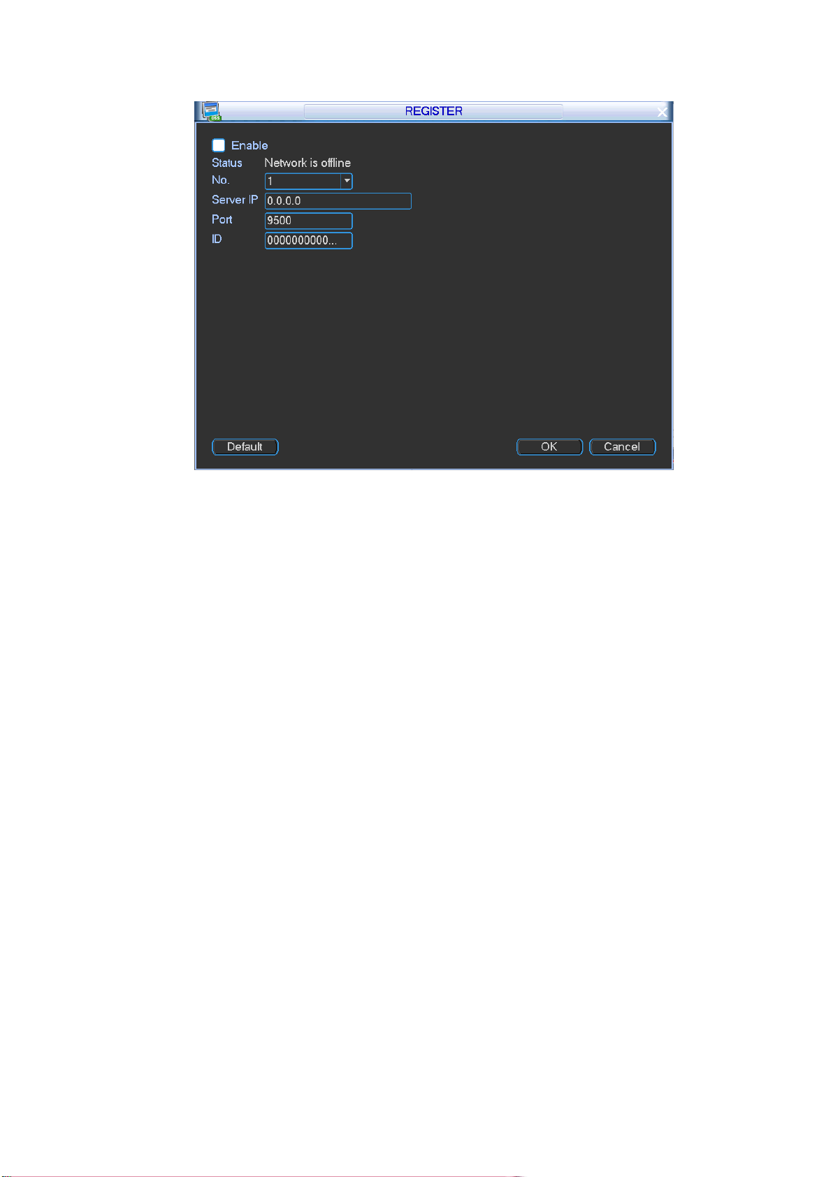
5.3 Auto Register
This function allows the device to auto register to the proxy you specified. In this way, you can
use the client-end to access the device and then view the video.
Step 1 On the main menu, from Vehicle->Register,
Enter Register interface. See Figure 5-4.
20
Figure 5-4
Step 2 Check the box to enable auto register function. Set server IP address, port and
sub-device ID.
Step 3 Click OK button.
Status is shown as online after successfully connection.
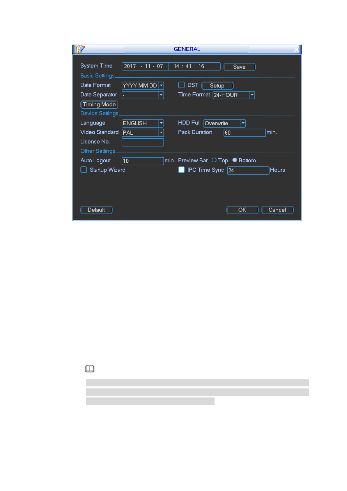
5.4 Set Plate Number
Set vehicle plate number so that device can overlay plate number on the video. It is to
recognize the vehicle.
Step 1 On the main menu, from Setting->General,
Enter General interface. See Figure 5-5.
21
Figure 5-5
Step 2 Set plate number.
Step 3 Click OK.
5.5 Reset Password
If you forgot admin password, you can reset the password by email or by answering the
security questions.
Please follow the steps listed below.
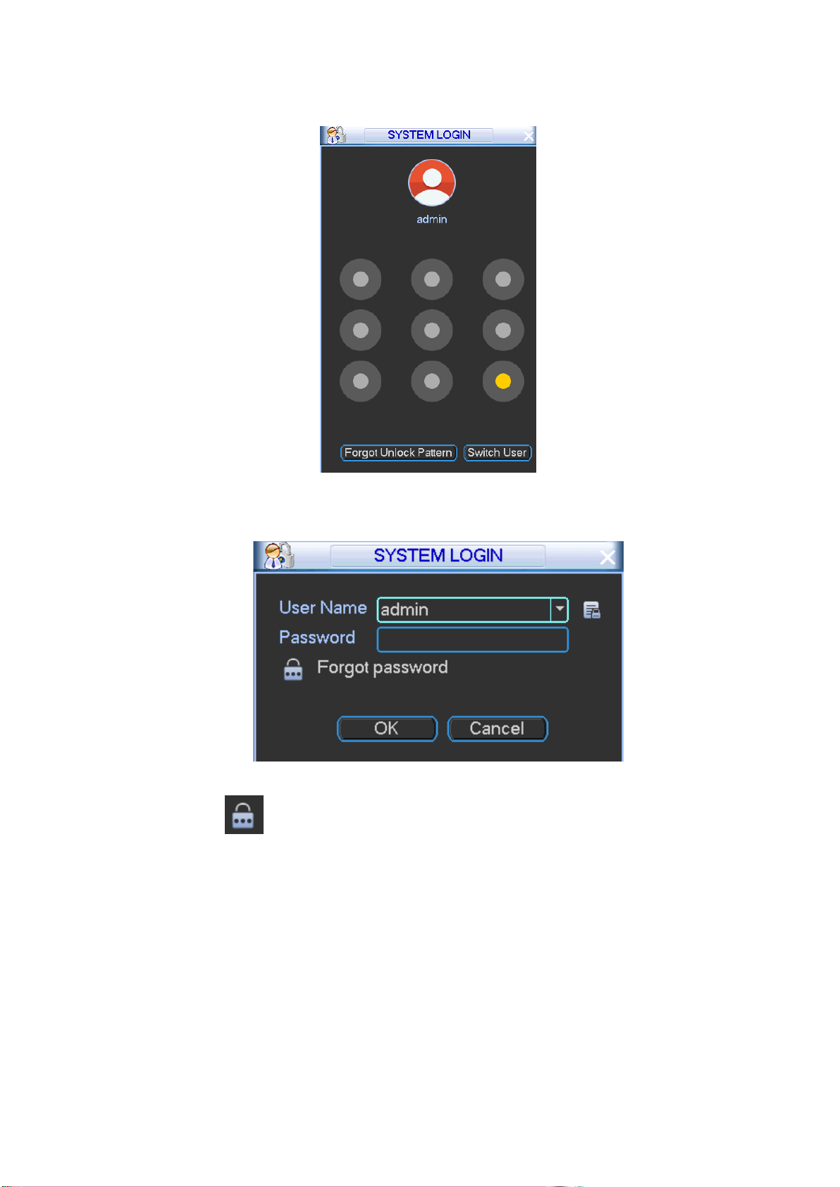
Step 1 Go to the device login interface. See
Step 2 Figure 5-6 or Figure 5-7.
If you have set unlock pattern, device displays unlock pattern login interface. See
Figure 5-6. Click “Forgot unlock pattern”, device goes to Figure 5-7.
If you have not set unlock pattern, device displays password interface. See Figure
5-7.
Note
Click Switch user button, NVR goes to general user login interface. The default
user name is admin. Click the user name and then select a user from the
dropdown list; you can login via other account.
22
Figure 5-6
Figure 5-7
Step 3 Click .
If you have not input email address information when you are initializing the
device, the interface is shown as in Figure 5-8. Please input an email address and
then click Next button, devices goes to Figure 5-9.
If you have input email when you are initializing the device, device goes to Figure
5-9.
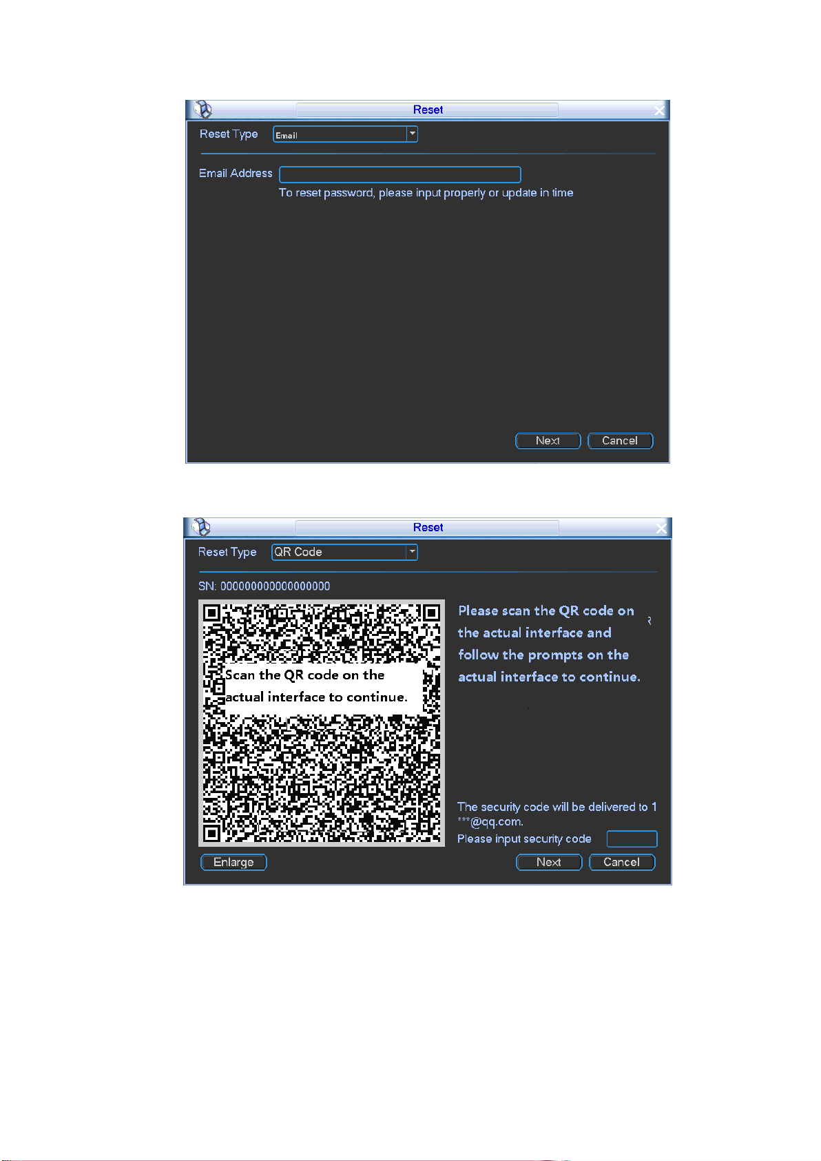
24
input the security code you get via the assigned email.
Warning
For the same QR code, max scan twice to get two security codes. Refresh
the QR code if you want to get security code again.
The security code on your email is only valid for 24 hours.
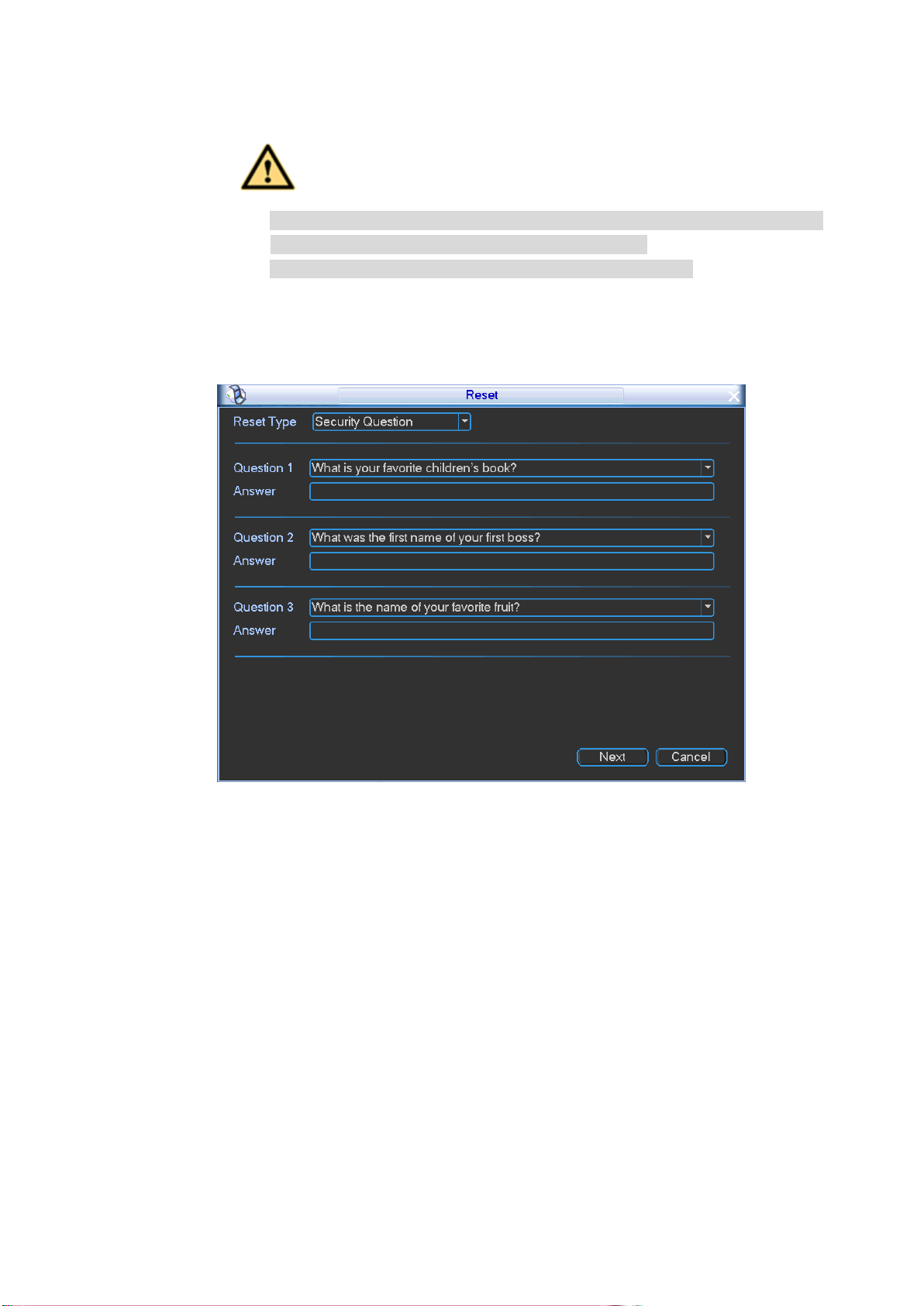
Security questions
In Figure 5-8, select security question from the drop down list. Device displays
security question interface. See Figure 5-10. Please input the correct answers
here.
Figure 5-10
Step 5 Click Next button.
Device displays reset password interface. See Figure 5-11.
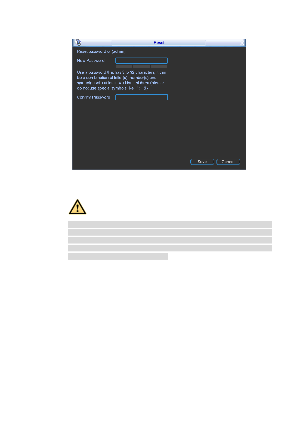
25
Figure 5-11
Step 6 Input new password and then confirm.
WARNING
STRONG PASSWORD RECOMMENDED-For your device own safety, please
create a strong password of your own choosing. The password shall be at least
8-digit containing at least two types of the following categories: letters, numbers
and symbols. We also recommend you change your password periodically
especially in the high security system.
Step 7 Click Save button to complete the setup.

26
6 FAQ
If you have any problems, please refer to the following contents first. Contact your local retailer
or service engineer if you have more questions.
6.1 About Boot up
1. Device cannot boot up.
Step 1 Check device power indicator light (PWR) is on or not.
If the power indicator light is off, check power voltage, ACC voltage, fuse is OK or
not. Use multimeter to check the device constant electricity and ACC voltage.
Go to Step 2 if the above items are OK.
Step 2 Check HDD box/SD card slot e-lock has been secured or not.
If the e-lock has not been secured, device cannot boot up.
Step 3 Check the problem results from the peripheral devices or not.
Step 4 Disconnect connected peripheral devices (such as camera), and then check the
device can boot up or not. Check the peripheral devices if device can properly boot up.
2. Device boots up repeatedly.
Step 1 Check the device has enabled no HDD reboot function or not.
Check the device has installed the HDD or not. Go to the main menu,
Vehicle->Abnormal to disable this function.
Step 2 The reboot results from the HDD malfunction.
The device may reboot if it cannot detect the HDD if the surrounding temperature is
too low. Please install the heat module.
6.2 No Record File
Device has no record files.
Step 1 Check device can detect HDD or not.
1. On the main menu, from Info->HDD to check HDD status is OK or not.
2. If there is no HDD, please refer to the user’s manual to install the HDD. If the HDD
is sleeping or has serious bad track issues. Please replace the HDD.
Step 2 Check device log. Check there is anyone has format the HDD.
Step 3 Check device record status. Change record mode as auto if necessary.
6.3 Positioning Module
GPS signal is not stable or has no signal.
Step 1 Check positioning satellite amount and signal strength can meet the requirements or
not.
Step 2 Check positioning module antenna is on the antenna dock or not.
Step 3 Check antenna is malfunction or not. Replace antenna to check.
Step 4 Check there is any interference from appliances on the vehicle. On the main menu,
from Info-Satellite, you can check the positioning module signal strength. If the signal

27
is clearly weak after open all appliances on the vehicle, that is to say, the appliances
on the vehicle may interfere the antenna. Please install the antenna again. If there is
still interference after install the antenna for several times, please use the shield
enclosure.
6.4 Network
1. 3G/4G dial fails. Cannot get IP address.
Step 1 Check device can detect 3G/4G module or not. Contact your local retailer or service
engineer for help.
Step 2 Check device can detect SIM card or no.
Step 3 Check 3G/4G module, SIM card, and operator settings.
Step 4 Refer to the antenna installation and adjustment contents; make sure antenna has
been properly installed.
Step 5 Check SIM card fee is not zero or the mobile flows are OK. Contact your mobile
operator for detailed information.
Step 6 Check 3G/4G parameters. Pay attention to APN, authentication mode, user name,
password and etc. Contact your operator for VPN parameters.
2. Cannot connect to DSS platform.
Step 1 Make sure the 3G/4G dial has succeeded. It can connect to the DSS platform.
Step 2 Check the device auto register parameters: server IP address, port and device ID.
Step 3 Check platform parameters. Make sure the platform parameters and device
parameters are the same.
3. After successfully connected to the DSS, the video is not fluent.
Step 1 The poor network signal may result in low video quality. Refer to the antenna
installation and adjustment contents; make sure you have properly installed the
antenna.
Step 2 Go to the DSS to make sure it is the sub stream you are watching. When you are
adding the device to the platform, please check sub stream.
Step 3 Device sub stream parameters are not proper. Set parameters such as bit stream,
frame rate according to the actual network environment.
Note
This quick start guide for reference only. Slight difference may be found on the user
interface.
All the designs and software here are subject to change without prior written notice.
All trademarks and registered trademarks mentioned are the properties of their
respective owners.
If there is any uncertainty or controversy, please refer to the final explanation of us.
Please visit our website or contact your local retailer for more information.