1.
Mobile Network Video Recorder
(8104 and 8208 Series)
User’s Manual
V
1.0.0
I
Foreword
Models
MNVR 8104 and 8208 Series
Safety Instructions
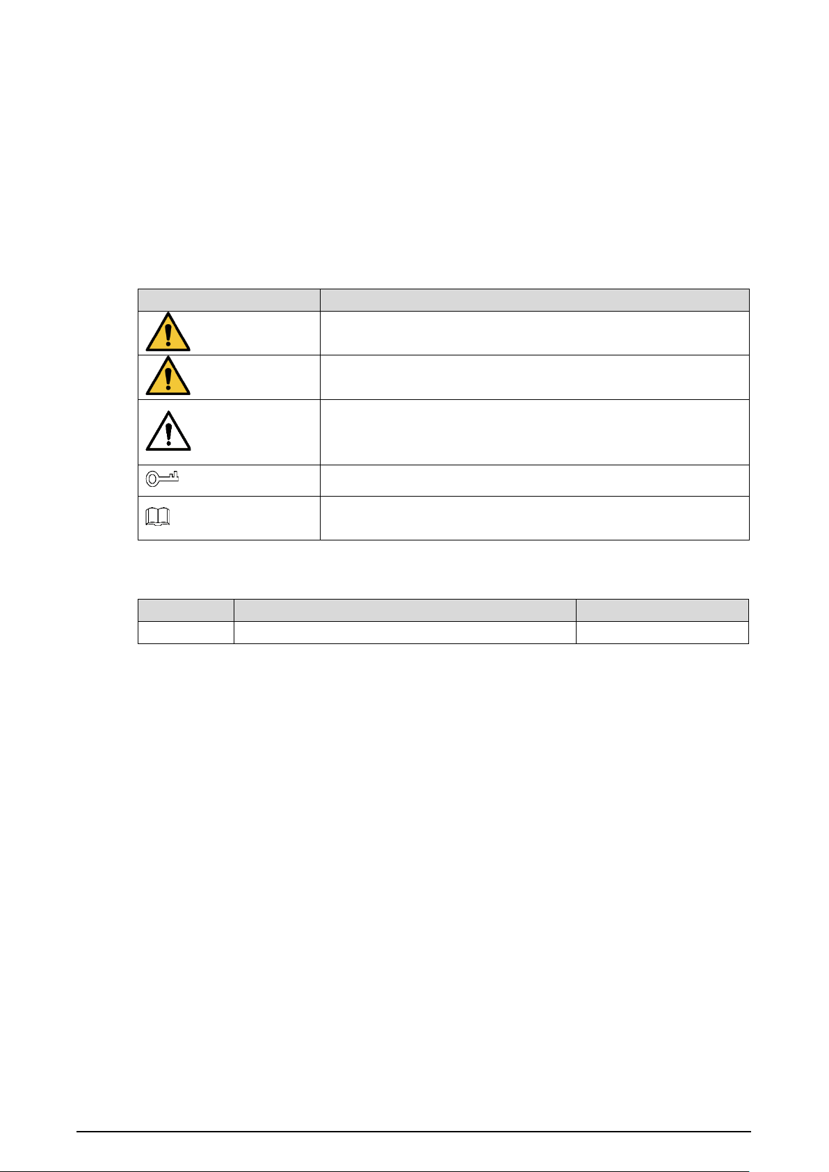
The following categorized signal words with defined meaning might appear in the manual.
Symbol Description
DANGER
Indicates a high potential hazard which, if not avoided, will result in
death or serious injury.
WARNING
Indicates a medium or low potential hazard which, if not avoided,
could result in slight or moderate injury.
CAUTION
Indicates a potential risk which, if not avoided, could result in
property damage, data loss, lower performance, or unpredictable
result.
TIPS
Provides methods to help you solve a problem or save you time.
NOTE
Provides additional information as the emphasis and supplement to
the text.
Revision History
Version Revision Content Release date
V1.0.0 First release. March 2023
About the Manual
The manual is for reference only. If there is inconsistency between the manual and the actual
product, the actual product shall prevail.
We are not liable for any loss caused by the operations that do not comply with the manual.
The manual would be updated according to the latest laws and regulations of related regions.
For detailed information, see the paper manual, CD-ROM, QR code or our official website. If
there is inconsistency between paper manual and the electronic version, the electronic version
shall prevail.
All the designs and software are subject to change without prior written notice. The product
updates might cause some differences between the actual product and the manual. Please
contact the customer service for the latest program and supplementary documentation.
There still might be deviation in technical data, functions and operations description, or errors
in print. If there is any doubt or dispute, please refer to our final explanation.
Upgrade the reader software or try other mainstream reader software if the manual (in PDF
format) cannot be opened.
All trademarks, registered trademarks and the company names in the manual are the properties
of their respective owners.
Please visit our website, contact the supplier or customer service if there is any problem
occurred when using the device.

II
If there is any uncertainty or controversy, please refer to our final explanation.

III
Important Safeguards and Warnings
This chapter describes the contents covering proper handling of the Recorder, hazard prevention,
and prevention of property damage. Read these contents carefully before using the Recorder,
comply with them when using, and keep it well for future reference.
Requirements
Do not place or install the Recorder near a heat source or where there is direct sunshine.
Do not install the Recorder in a humid, dusty, or smoggy place.
Install the Recorder horizontally or in a stable place. Take measures to prevent it from falling.
Do not drip or splash liquid onto the Recorder. Make sure that the Recorder does not bear any
objects filled with liquid to prevent liquid from flowing into the Recorder.
Prevent foreign objects from entering the Recorder, which might result in damage.
Install the Recorder in a place with good ventilation. Do not clog the air vents of the Recorder.
Use the Recorder only within the rated input and output range.
Do not dismantle the Recorder without permission.
Do not transport the Recorder with the front panel on the bottom.
Transport, use and store the Recorder under the allowed humidity and temperature conditions.
Do not expose the Recorder to water or excessive moisture when washing the car. A failure to
follow this instruction might result in short circuit, fire, or other malfunctions.
The dust on the circuit board will cause short circuit, which affect the normal operation of the
Recorder and even damage the Recorder. To make the Recorder work stably for a long time,
please regularly use the brush to remove the dust from components, including circuit board,
connectors, and chassis.
Keep the Recorder installed horizontally and make sure the internal anti-vibration components
work properly.
Unlock the HDD box before pulling it out; otherwise there might cause damage to the Recorder.
After all the cables are connected, tie up the cables to avoid the dangers such as short circuit,
heat and electric shock resulted from loose cables.
When a Recorder is connected with a car mount display, mount the camera at least 2m away
from the display. If the camera and display are too close, tune down the volume of the car
mount display to avoid squeal.
Power Requirements
Use the battery exactly as prescribed; otherwise, the battery might catch fire or explode!
Always replace with the same type of batteries!
Use the wires (power cords) recommended for the region where the Recorder is used within the
specified range of specifications!
The appliance coupler is a disconnection Recorder. Keep a convenient angle when using it.
Take care to complete the circuit connection. A failure to follow this instruction might result in
Recorder damage.
Prevent short circuit from occurring on all external wiring parts.
After all the lines connections are completed, you can start connecting power cable.

IV
Ensure the project is well grounded to avoid interference to video and audio signals and avoid
electrostatic or induced voltage to damage the Recorder.
Unplug the power cable before you remove the audio/video signal cable, RS-232 or RS-485
cable; otherwise these ports might be damaged.

V
Table of Contents
Foreword ........................................................................................................................................................... I
Important Safeguards and Warnings ......................................................................................................... III
1 Product Introduction .................................................................................................................................. 8
Overview ....................................................................................................................................................................................... 8
Functions ....................................................................................................................................................................................... 8
Unpack and Check ..................................................................................................................................................................... 9
2 Structure and Installation ........................................................................................................................ 11
Structure ...................................................................................................................................................................................... 11
2.1.1 Front Panel .................................................................................................................................................................... 11
2.1.2 Rear Panel ...................................................................................................................................................................... 12
2.1.3 Port Description .......................................................................................................................................................... 13
2.1.4 Dimensions ................................................................................................................................................................... 17
Installation .................................................................................................................................................................................. 17
2.2.1 Installing HDD .............................................................................................................................................................. 18
2.2.2 Installing SIM and SD Card ...................................................................................................................................... 20
2.2.3 Installing Antenna ...................................................................................................................................................... 20
2.2.4 Fixing the Recorder .................................................................................................................................................... 22
2.2.5 Connecting Cable ....................................................................................................................................................... 24
3 Basic Settings ............................................................................................................................................... 30
Booting up Recorder ............................................................................................................................................................... 30
Initializing Recorder ................................................................................................................................................................ 30
Logging in to Recorder .......................................................................................................................................................... 32
Configuring IP Address .......................................................................................................................................................... 34
Configuring General Settings .............................................................................................................................................. 36
3.5.1 Setting General Information ................................................................................................................................... 36
3.5.2 Date and Time Settings............................................................................................................................................. 36
Configuring Remote Recorders .......................................................................................................................................... 38
3.6.1 Initializing the Remote Recorder .......................................................................................................................... 38
3.6.2 Adding a Remote Recorder ..................................................................................................................................... 41
3.6.3 Modifying IP Address of Remote Recorder ....................................................................................................... 43
Configuring Record ................................................................................................................................................................. 44
Storage Plan ............................................................................................................................................................................... 46
3.8.1 Configuring Recording Schedule.......................................................................................................................... 46
3.8.2 Configuring Snapshot Schedule ........................................................................................................................... 47
4 Function Modules Operations ................................................................................................................ 49
Live ................................................................................................................................................................................................ 49
4.1.1 Live Channels ............................................................................................................................................................... 50
4.1.2 Voice Talk ........................................................................................................................................................................ 51
4.1.3 PTZ Control.................................................................................................................................................................... 52
Record Playback ....................................................................................................................................................................... 56
4.2.1 Playback Control Bar .................................................................................................................................................. 57
4.2.2 Playing Back Video Recordings .............................................................................................................................. 57
4.2.3 Clipping Recording File ............................................................................................................................................ 59
Viewing Alarm Info .................................................................................................................................................................. 60

VI
5 System Settings ........................................................................................................................................ 61
Configuring Alarm Event Settings ..................................................................................................................................... 61
5.1.1 Configuring Video Detect Settings ...................................................................................................................... 61
5.1.2 Configuring Alarm Input Settings ........................................................................................................................ 64
5.1.3 Configuring Exception .............................................................................................................................................. 66
5.1.4 Configuring Alarm Out Settings ............................................................................................................................ 68
Configuring AI Settings.......................................................................................................................................................... 69
5.2.1 Face Detection and Recognition ........................................................................................................................... 70
5.2.2 Active and Safe Drive ................................................................................................................................................. 81
5.2.3 Number Plate................................................................................................................................................................ 88
5.2.4 Passenger Flow Measurement ............................................................................................................................... 90
Backing up File .......................................................................................................................................................................... 91
Configuring Display Output Settings ............................................................................................................................... 93
5.4.1 Tour Settings ................................................................................................................................................................. 93
5.4.2 TV Adjustment ............................................................................................................................................................. 95
5.4.3 Video Mirror Settings ................................................................................................................................................. 95
Configuring Camera Parameters ........................................................................................................................................ 96
5.5.1 Camera Properties ...................................................................................................................................................... 96
5.5.2 Encode Parameters .................................................................................................................................................... 97
5.5.3 PTZ ................................................................................................................................................................................. 102
5.5.4 Channel Type ............................................................................................................................................................. 103
5.5.5 PoE ................................................................................................................................................................................. 104
Configuring Network Parameters ................................................................................................................................... 105
5.6.1 Port ................................................................................................................................................................................ 105
5.6.2 Wireless Network...................................................................................................................................................... 106
5.6.3 Cellular ......................................................................................................................................................................... 109
5.6.4 Email ............................................................................................................................................................................. 110
5.6.5 Register ........................................................................................................................................................................ 112
5.6.6 P2P ................................................................................................................................................................................. 113
5.6.7 Operation Platform ................................................................................................................................................. 114
Managing Storage Device ................................................................................................................................................. 114
5.7.1 Basic .............................................................................................................................................................................. 114
5.7.2 Disk Manager ............................................................................................................................................................. 115
5.7.3 FTP ................................................................................................................................................................................. 116
Configuring System .............................................................................................................................................................. 118
5.8.1 Configuring Serial Port Parameters ................................................................................................................... 118
5.8.2 Managing Security .................................................................................................................................................. 119
5.8.3 Configuring Vehicle Info ........................................................................................................................................ 120
Managing User Account ..................................................................................................................................................... 123
5.9.1 Managing User .......................................................................................................................................................... 124
5.9.2 Managing ONVIF User ............................................................................................................................................ 126
5.9.3 Managing Group ...................................................................................................................................................... 128
5.9.4 Resetting Password ................................................................................................................................................. 129
6 Update ........................................................................................................................................................ 133
System Version ....................................................................................................................................................................... 133
Update ....................................................................................................................................................................................... 133
7 System Maintenance ................................................................................................................................. 135

VII
Requirement for Maintenance ......................................................................................................................................... 135
System Information .............................................................................................................................................................. 135
7.2.1 Log ................................................................................................................................................................................. 135
7.2.2 Network Info .............................................................................................................................................................. 136
7.2.3 Disk ................................................................................................................................................................................ 136
7.2.4 Channel Info............................................................................................................................................................... 137
7.2.5 Satellite Info ............................................................................................................................................................... 137
Automatic Maintenance ..................................................................................................................................................... 138
7.3.1 Auto Reboot ............................................................................................................................................................... 138
7.3.2 Auto Boot up ............................................................................................................................................................. 139
7.3.3 Auto Shutdown System ......................................................................................................................................... 139
7.3.4 Acc Delay ..................................................................................................................................................................... 140
Backup and Restore .............................................................................................................................................................. 140
7.4.1 Backing up Configurations ................................................................................................................................... 140
7.4.2 Importing Configurations ..................................................................................................................................... 141
7.4.3 Restoring to Default ................................................................................................................................................ 142
Network Sniffer ...................................................................................................................................................................... 143
8 Operating by DSS ................................................................................................................................... 145
9 FAQ ............................................................................................................................................................ 146
Mouse Operations ................................................................................................................. 150
HDD Capacity Calculation .................................................................................................... 152
Cybersecurity Recommendations ........................................................................................... 153

8
1 Product Introduction
Overview
MNVR 8104 and 8208 series mobile video monitoring products are developed on the new
generation of platform, integrating video, locating, driving recording and intelligent analysis. This
product can be widely used for car mount monitoring in public transportation, long-range
passenger transport, police patrol, urban management patrol, cash carriers, hazardous goods
transport, and logistics transport, or video monitoring in harsh environments.
It has the following features:
4/8 channels of IPC input and 2 channels of HDCVI analog video input.
H.264/H.265 encoding ensures high encoding efficiency and saves storage space.
Netcom wireless network modules (3G, 4G and Wi-Fi modules are optional) are built in after full
consideration of network application needs of vehicle mount products.
Professional car-mount design in standard size features low power consumption and novel
shape.
Wide power voltage range adapts to various car mount power supply.
Unique HDD and SD card storage design makes recording backup and management easier.
Functions
Function Description
Removable HDD
The extractable and seismic design make you lock and move the HDD
easily to realize data backup. Just connect the removable HDD to the USB
port of PC, you can perform data-related operations conveniently.
Storage
Stores the data in the dedicated format which cannot be falsified and
ensures the data security.
Compression
Supports multi-channel audio and video signals, and each channel signal
supports real-time compression by independent hardware to realize the
sync between sound and image.
Backup
Plug in a USB storage device (such as USB flash drive and mobile HDD)
to back up.
You can back up the data by downloading the files from the Recorder
HDD and SD card through Internet.
Video playback
Every channel supports real-time and independent recording, and you
can pla
y backward, monitor on Internet, query and download
recordings.
Supports several playback modes:
Slow playback, fast playback,
backward playback, and frame-by-frame playback.
Displays time when the event occurred during playback.
Operation through
network
Supports remote operations through network, such as real-time remote
monitoring, recorded video search and playback, and PTZ control.
9
Alarm linkage
Outputs
signals such as car door signal, cornering lamp signal,
reversing and braking signal, to give an indication and take a record.
Supports two channels of electric level alarm output to realize easy
alarm linkage.
Supports protective circuit for alarm input port and alarm output port,
which protect the Recorder from damage.
Communication
interfaces
Offers RS-485 interfaces to connect to external Recorders.
Offers RS-232 interfaces to connect to external car mount display.
Offers standard Ethernet ports that support remote network
accessing.
Smart operations
Mouse operations.
The same settings in the menu can be quickly copied and pasted.
Satellite positioning
Supports positioning function and recording linkage. Recording search can
be linked with vehicle moving track.
Cellular, Wi-Fi
networks
Adopts the latest wireless communication technology, which has improved
the manageability of the Recorder.
Dual stream
To cope with the low-bandwidth and instability of wireless network, the
Recorder adopts the dual stream technology (respectively encode the
real-time video and encode video in network transmission) to optimize the
coding of network transmission, which improves the control capability of
wireless network transmission.
Rollover and
collision detection
The integrated G-sensor supports rollover and collision detection and
timely releases alarms through the platform.
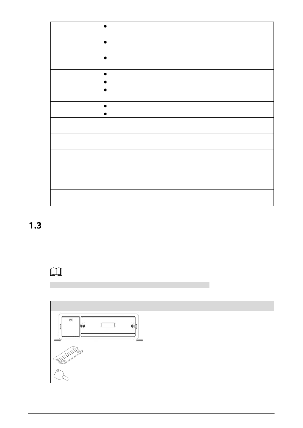
Unpack and Check
When you receive the device, unpack the box for checks.
Firstly, check if there is any damage on the device appearance. Secondly, open the accessory box to
check if the accessories are complete against the packing list.
For tools or accessories not mentioned in the list, please purchase them.
Table 1-1 Packing list
Figure Name Quantity
Device 1
Lug 2
Pass key 2
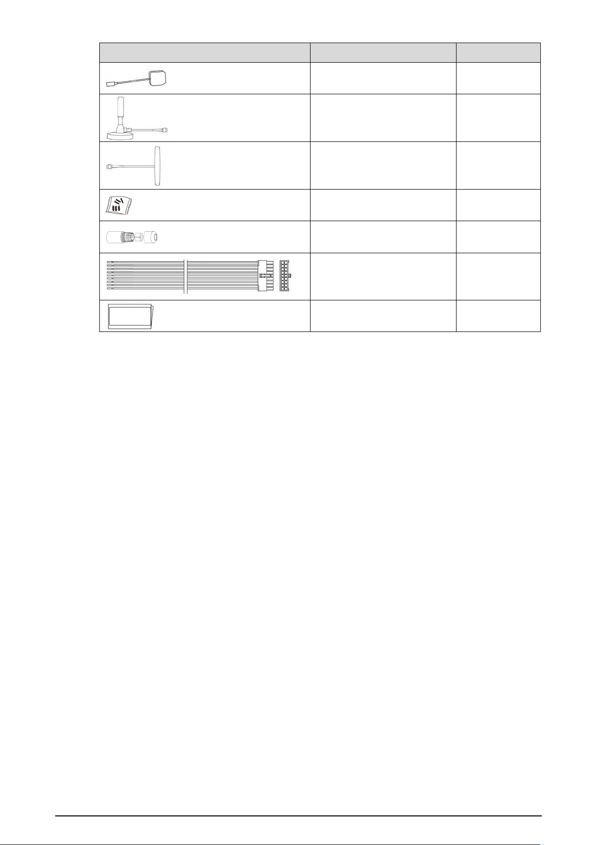
10
Figure Name Quantity
GPS antenna 1
3G/4G antenna 1
Wi-Fi antenna 1
Accessories bag 1
Network port waterproof
connector
1
Alarm signal connector 1
Quick start guide 1
Matching Product (not supplied)
1. DSM camera
2. ADAS camera
3. SD card
4. SIM card
5. HDD (max. 2 TB per disk)
11
2 Structure and Installation
Describes the installation of hardware. Prior to installation, you need to know about the front panel,
rear panel, structural sizes, and interface definition of the device. Then you can install corresponding
HDD, SIM card, SD card, antenna, and devices.
The following figures are for reference only, and the actual product shall prevail.
Structure
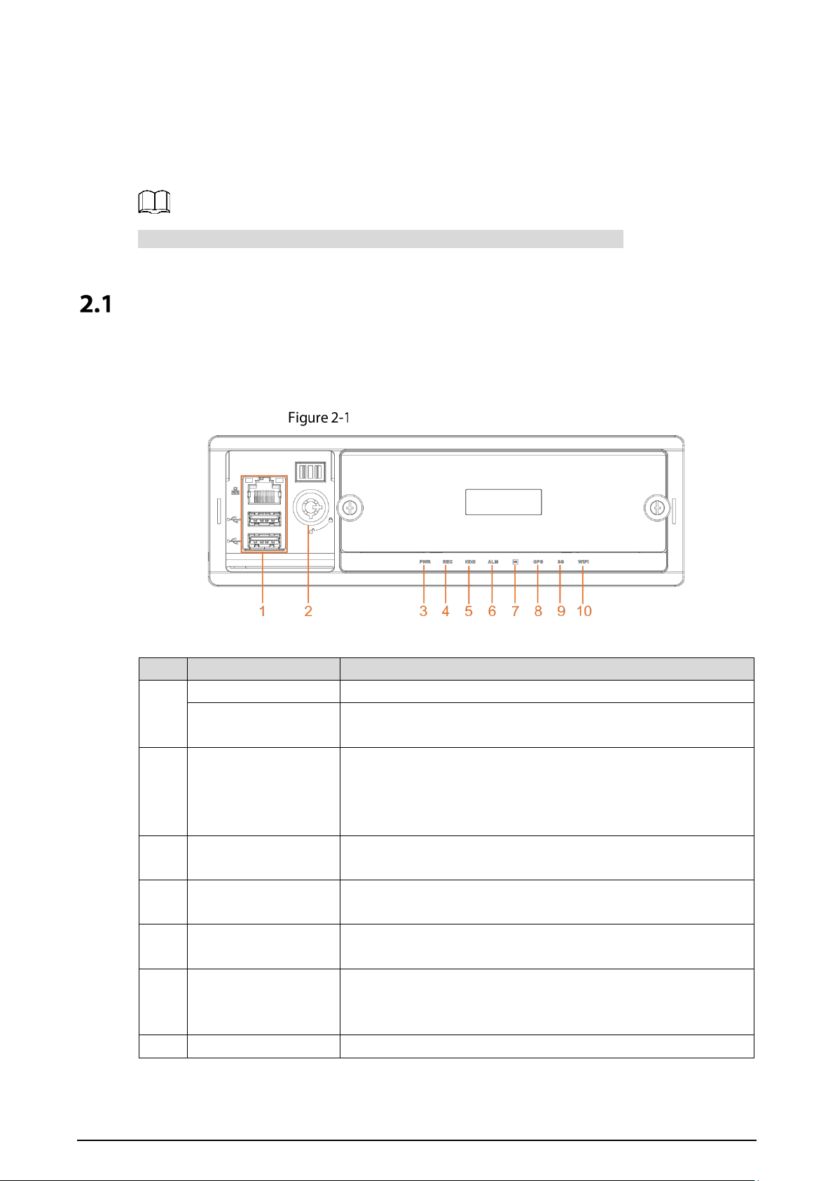
2.1.1 Front Panel
Front panel of MNVR8104/8208
Table 2-1 Descriptions of interfaces and indicators
No. Item Description
1
RJ-45 network port One network port.
USB interface
Two USB ports that connect to peripheral devices such as USB
storage device and mouse.
2
Lock switch (Device
switch)
When pulling out HDD, the Device must be unlocked, and if the
Device is turned on, it will shut down automatically.
To protect the HDD, this Device cannot be turned on if it is
unlocked. Turning on the device only after locking it
3 PWR
The red light is always on when the Device is powered on, and off
when the Device is powered off
4 REC
Recording status indicator. The blue light is always on when
recording, and off when not
5 HDD
HDD status indicator. The light keeping blue indicates that there
is HDD and the light off indicates no disk.
6 ALM
Alarm status indicator. The light keeping red indicates alarm of
video loss, low battery and high temperature and off when no
alarm occurs.
7 IR Receives infrared signal from remote control.

12
8 GPS
GPS status indicator. Glows blue when GPS positioning is
working properly, and the indicator is off when GPS function is
not enabled.
This function is supported on the Device with GPS positioning
module.
9 3G
3G status indicator. Glows blue when 3G dial-up is working
properly, and the indicator is off when 3G function is not
enabled.
This function is supported on the Device with 3G module.
10 Wi-Fi
Wi-Fi status indicator. Glows blue when Wi-Fi connection is
correct, and the indicator is off when Wi-Fi is disconnected.
This function is supported on the Device with Wi-Fi module.
2.1.2 Rear Panel
The illustration of the rear panels of the Recorder. Table 2-2 describes interface functions. For
interface definitions, see "2.1.3 Port Description."
Rear panel
Table 2-2 Descriptions of rear panel interfaces
No. Port Description
1
Positioning
antenna
port
Connects with positioning antenna for receiving satellite positioning signals.
This function is supported on the Recorder with positioning module.
2
Wi-Fi
antenna
port
Connects to Wi-Fi antenna and receives Wi-Fi signals.
This function is supported on the Recorder with Wi-Fi module.
13
3
3G/4G
antenna
port
Connects to 3G/4G antenna for receiving 3G/4G signals.
This function is supported on the Recorder with 3G/4G modules.
4 VGA Outputs analog video data to the connected display with VGA port.
5 DSM Connects to camera that detects tired face.
6 ADAS
Connects to camera that helps drive.
7 SPK port
Connects to mobile small-size display to show information and give out voice
reminding. See "2.1.3.7 SPK."
8
IPC1-4
Connects to IP camera.
Different devices corresponds to different number of channels
IPC5-8
9
Power
cable
Connects to DC 6V-DC 36V power supply for getting power from the car
accumulator.
The red end with fuse is the anode of the power supply (always-live
wire).
The black wire is the ground wire.
The orange one is the ACC signal (key starting wire).
10
ALARM/C
AN/485
Alarm input/output port: Includes alarm input/output port, grounding,
and 12V output port.
CAN port: Used for data transfer between the Device and vehicle
CAN network or other devices with CAN port
A, B: Controls PTZ operations.
11
Voice talk
port
Connects to voice talk device.
12
EXTEND
port
See "2.1.3.3 Extend."
13
HDMI
interface
Used to connect with HDMI display.
2.1.3 Port Description
This Manual only describes functions of all jacks of each interface. You can follow these
descriptions to prepare cables or contact our sales staff for purchasing cables.
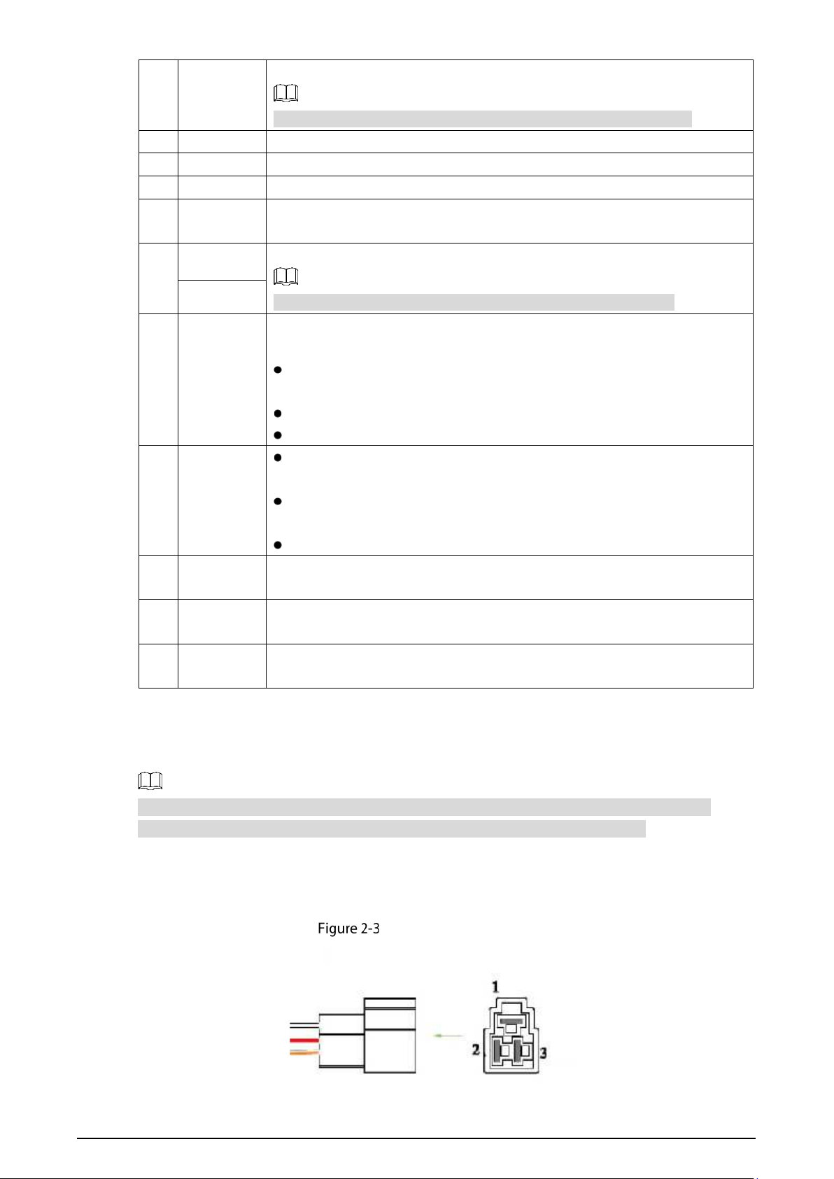
2.1.3.1 Power Input
Power input interface
14
Table 2-3 Power input interfaces (left to right)
No.
Description
1 Ground cable (in black)
2 Anode input (in red)
3 ACC signal input (in orange)
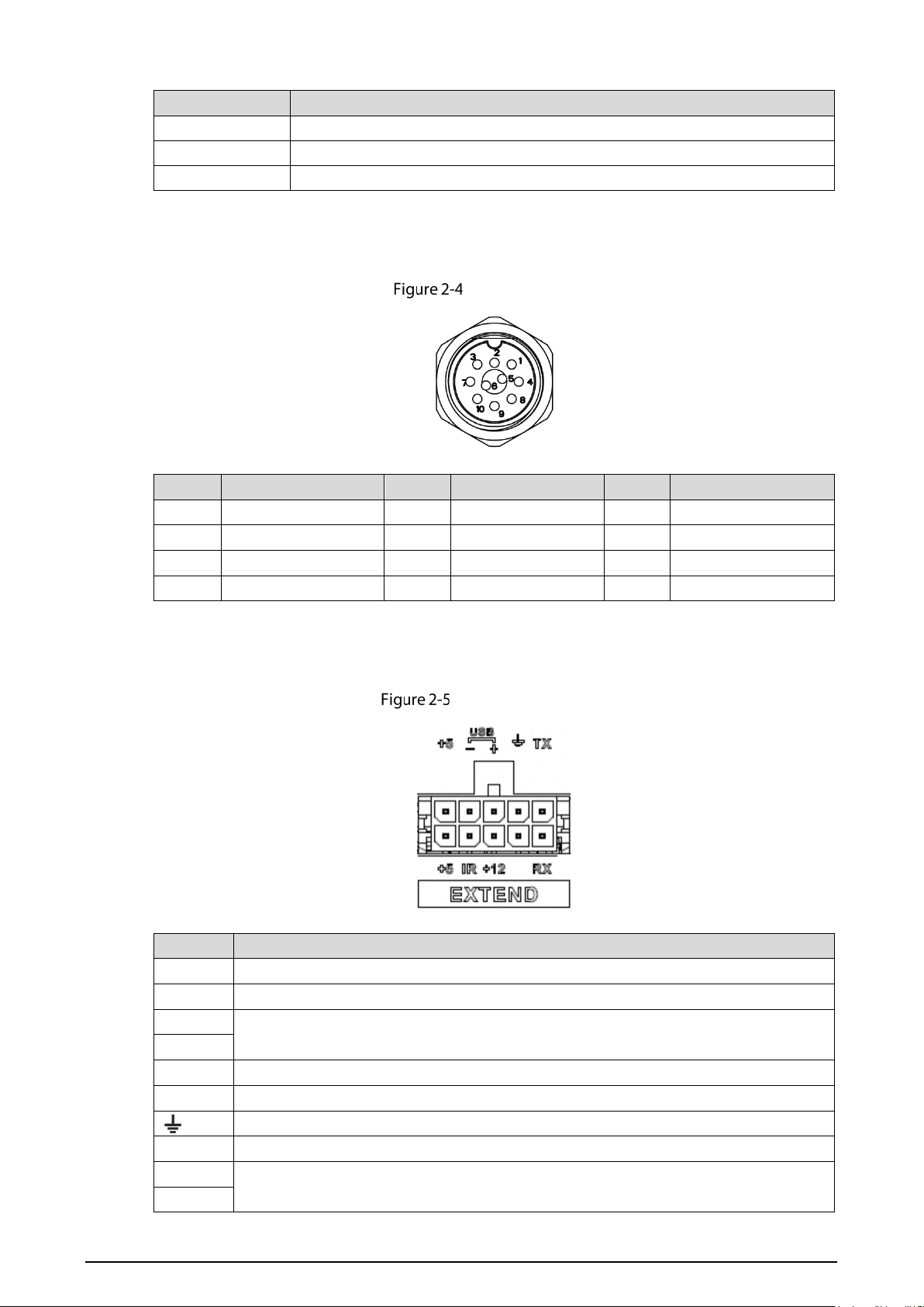
2.1.3.2 VGA
VGA port
No.
Function
No.
Function
No.
Function
1 +12V/1A output 5 Audio output 9 VGA line sync
2 Ground line 6 VGA_B 10 VGA field sync
3 VGA_G 7 VGA_R
—
—
4 RXD_232 8 TXD_232
—
—
2.1.3.3 Extend
EXTEND port
Name
Function
+5
USB +5V (up)
+5 USB +5V (low)
-
USB data- and USB data+ that connect to USB port.
+
IR Reserved for custom.
+12
+12V/1A output.
Ground
VO AV video output
RX
RS-232 serial port sender and receiver that connects to RS-232 port
TX
15
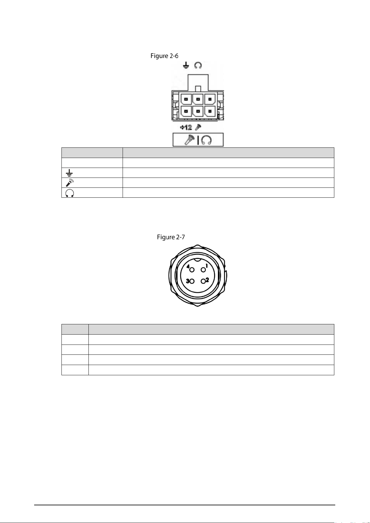
2.1.3.4 Voice Talk
Voice talk port
Name
Function
+12 +12V output
Ground
Mic In that can connect to microphone.
Mic Out that can connect to earphone.
2.1.3.5 DSM
DSM port
Table 2-4 DSM port description
No. Description
1 VCC
2 Power source ground port
3 Audio signal port
4 Video signal port

16
2.1.3.6 ADAS
ADAS port
Table 2-5 ADAS port description
No.
Description
1 VCC
2 Power source ground port
3 Audio signal port
4 Video signal port
2.1.3.7 SPK
SPK port
Table 2-6 SPK port description
No.
Description
1 12V_EXT
2 GND
3 RXD_232
4 TXD_232
5 AUDIO_OUT
6 AUDIO_GND
7 NC
17
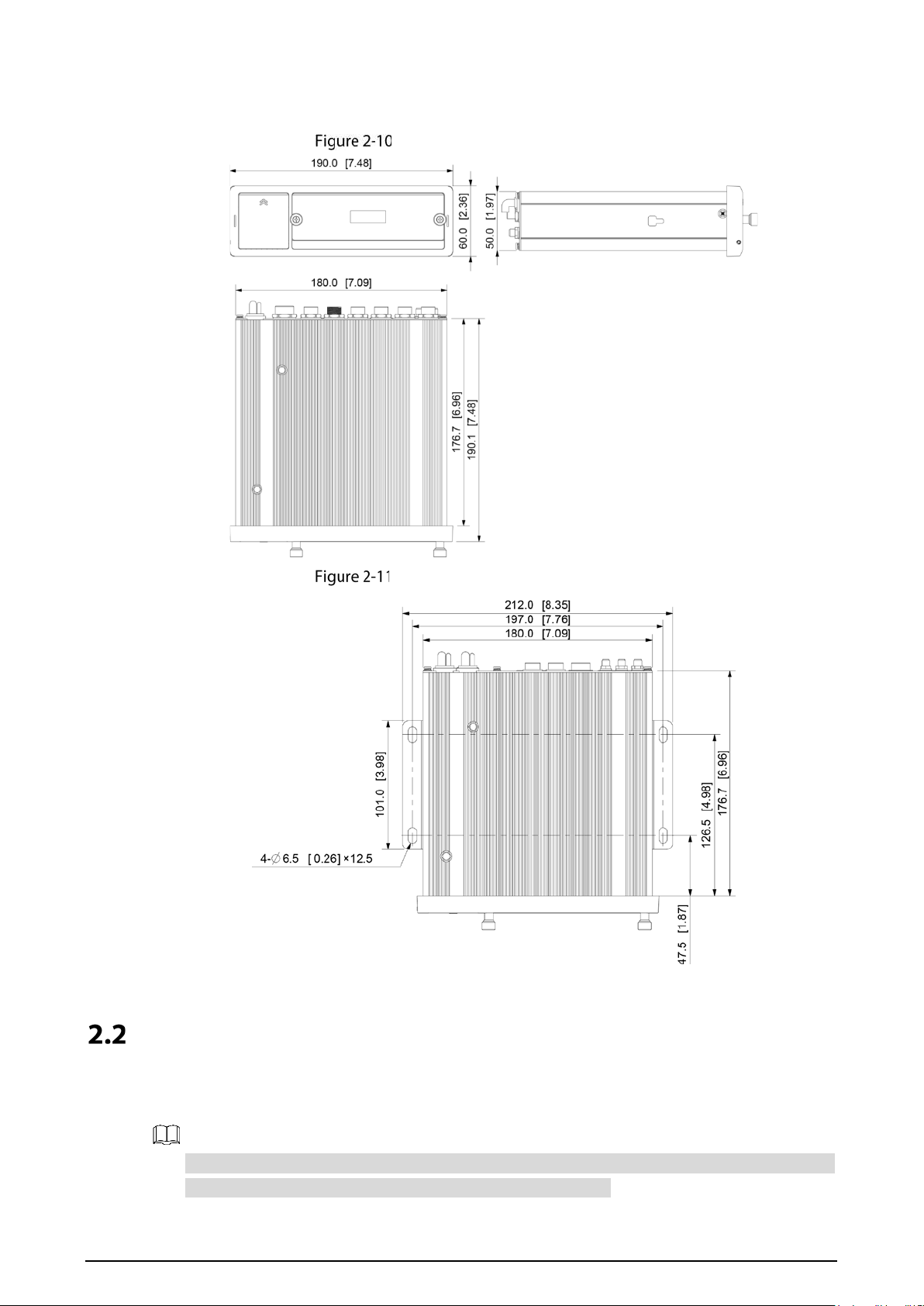
2.1.4 Dimensions
Dimension (1) [Unit: mm (inch)]
Dimension (2) [Unit: mm (inch)]
Installation
When you receive the Recorder, unpack the box to check the Recorder appearance and
structures, and then install the SIM card and SD card.
Before completing the installation, make sure the Recorder is disconnected from power, and do
not plug or unplug components when the power is connected.
18
After the installation is complete, the Device electronic lock must be in "locked" status before
powering on the Device.
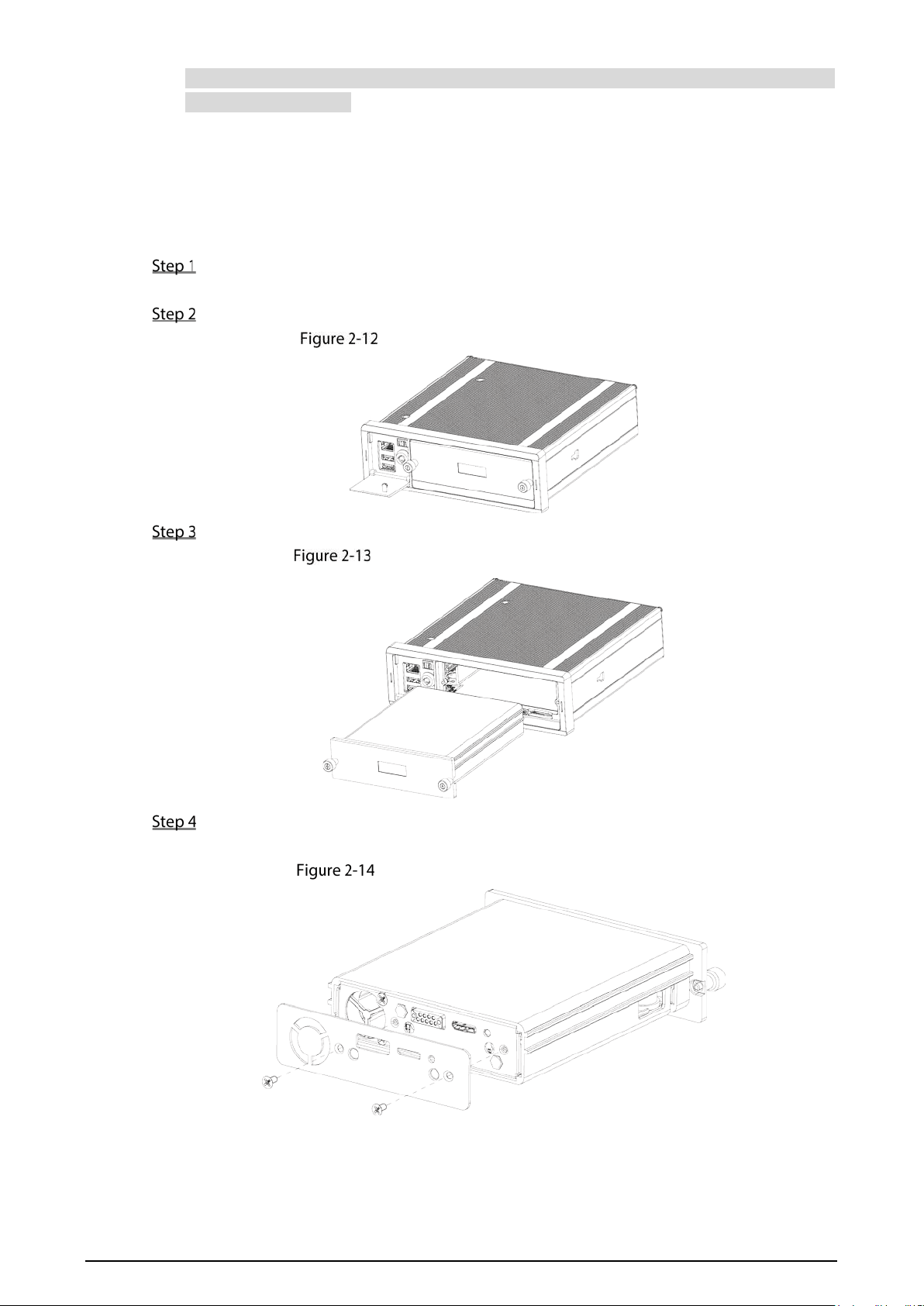
2.2.1 Installing HDD
MNVR8104 series support 1 HDD, and MNVR8208 series support dual HDDs. This chapter
takes MNVR8208 series for example.
Gently press the left front cover.
The left front cover automatically opens.
Use a pass key to unlock the door.
Open door lock switch (dual HDDs).
Loosen the two screws at the front panel and take out the HDD carrier along the guide rail.
Take out the HDD carrier (dual HDDs).
Loosen two screws on the back panel of the HDD carrier, take out the rear carrier panel, and
remove the HDD carrier enclosure.
Remove the HDD carrier (dual HDDs)
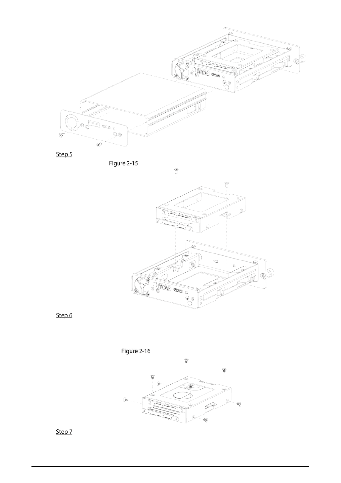
19
Loosen two screws of the HDD holder and remove the holder.
Remove the HDD holder (dual HDDs)
Use four screws to fix each HDD and the HDD holder, and install the HDD holder back to the
Recorder.
Fix the upper HDD to the top of the HDD holder, and the lower HDD to the side of the HDD
holder.
Installing HDD (dual HDDs)
Install the HDD carrier enclosure in place along the rails, and then fix the HDD enclosure rear
panel with two screws.
20
Place the HDD carrier back to the Recorder, tighten two screws and close the door lock.
2.2.2 Installing SIM and SD Card
By default, the Device is delivered without the SIM card and SD card. Install them as you need.
To set up a dial up network connection, you need to purchase and install your own SIM card.
To store recording data, you need to purchase and install an SD card.
Only standard SIM card is supported.
Push the SIM card pinhole using a pin, and then pull out the card slot.
Put the SIM card into the slot.
Push back the card slot.
Preparation
The Recorder is powered off.
Procedure
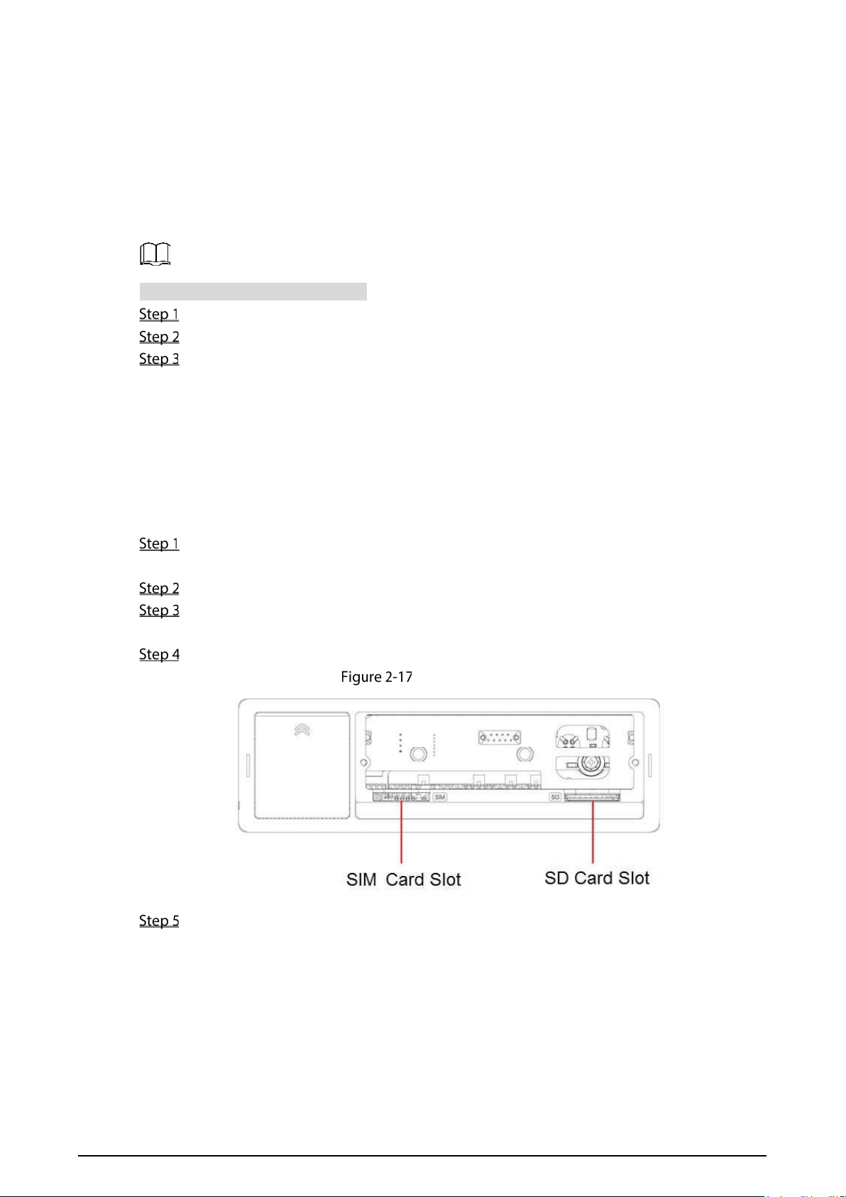
The SIM card slot and SD card slot are inside the Device.
Gently press the left front cover.
The left front cover automatically opens.
Use the pass key to unlock the Recorder.
Loosen the two screws at the front panel and take out the HDD carrier along the guide rail.
Open the card slot cover. You can see SIM card slot and SD card slot in Figure 2-17.
Insert SIM card and SD card into the slot, and then push back the slot.
Install SD card
Close the slot cover, and then use the pass key to lock the Recorder.
2.2.3 Installing Antenna
The Recorder antenna is installed to connect the Recorder to the network and to locate the
position of the vehicle.
21
2.2.3.1 Installing Network Antenna
When installing sticking antenna, make sure there is no metal material below the sticking spot.
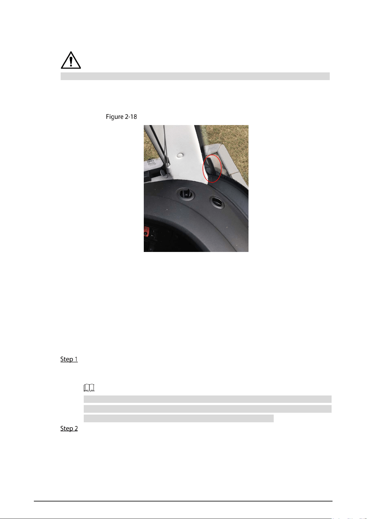
For installation of mobile network antenna, see Figure 2-18. The flat antenna is recommended
to be vertically attached to near the wind shield (such as on the instrument panel, or under the
wind shield), or concealed inside the instrument panel.
Inside installation of mobile network antenna
2.2.3.2 Installing Antenna
Positioning method include the currently mainstream GPS positioning, with corresponding GPS
antenna.
In this manual, GPS antenna is used as an example to illustrate the installation steps of locating
antennas. The installation process of other locating antenna is identical.
2.2.3.2.1 Outside Installation
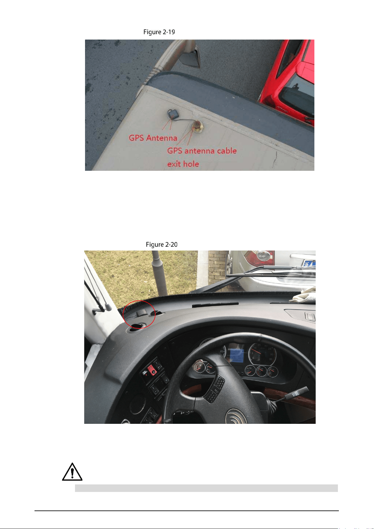
Place the GPS antenna on the left front of the roof. See Figure 2-19.
The antenna is magnetically attached to the roof of the vehicle. For more reliable fixation,
the GPS antenna can be pasted on the roof with 3M adhesive in the accessories.
To make the sensitivity and accuracy of positioning free of interference, ensure that
there is no high-power electrical or electronic interference source (such as a fan or AC
compressor) or obstacles within 1 meter around the GPS antenna.
Insert the GPS antenna lead wire into the antenna lead hole on the roof of the vehicle and
connect to the GPS antenna port inside the vehicle.
The requirements of the GPS antenna lead hole are as follows.
The inner radius is at least 10mm.
It must be waterproof.
Easy to replace and maintain the antenna.
22
Outside Installation
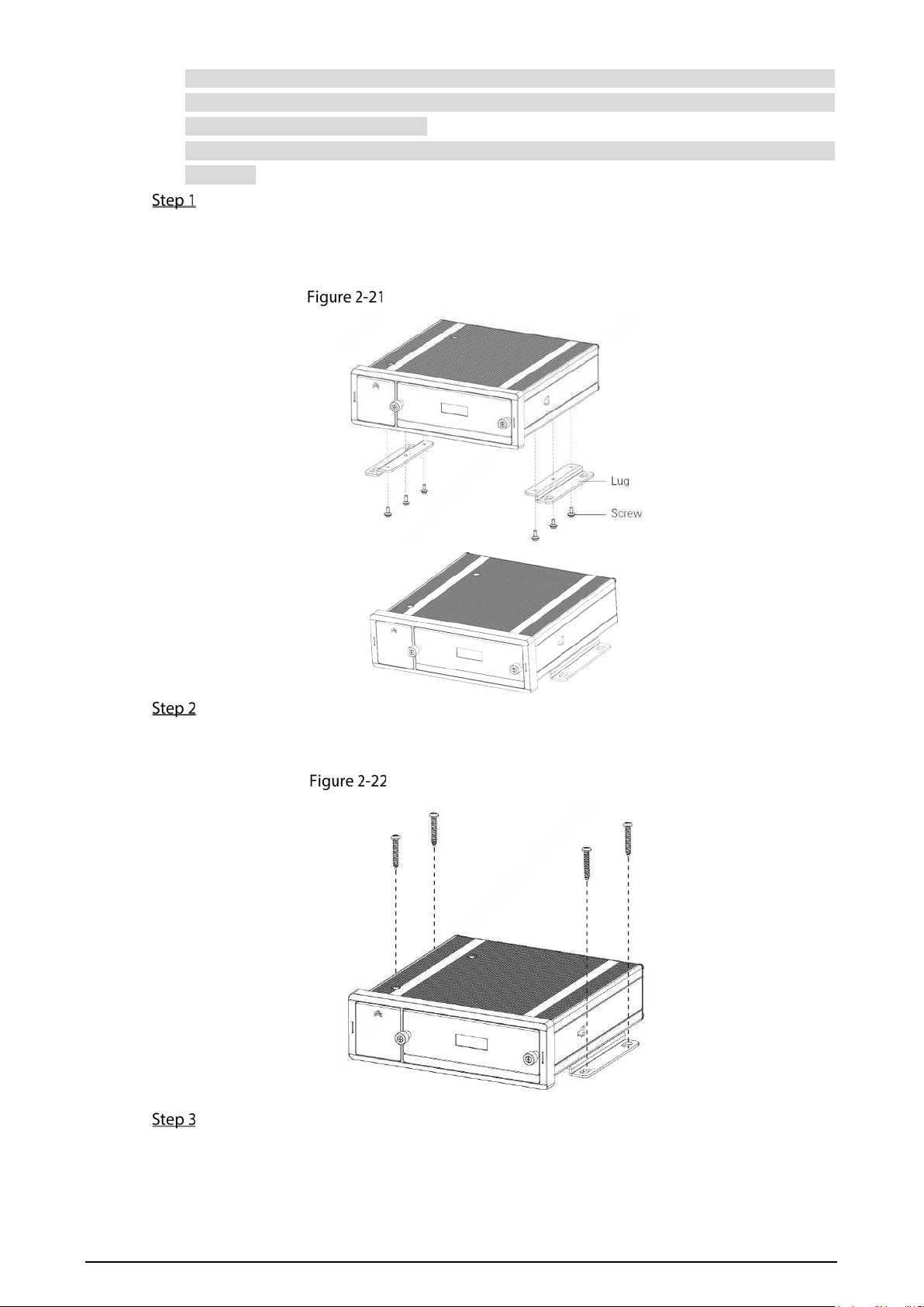
2.2.3.2.2 Inside Installation
When limited by waterproof and wiring requirements, the antenna can be installed inside the
vehicle.
You can place the antenna horizontally on the dashboard close to the windshield, and make the
GPS cable facing upward to enhance the signal, as shown in Figure 2-20.
Inside Installation
2.2.4 Fixing the Recorder
Install the Recorder on the vehicle where it cannot be seen from outside. Avoid places with
23
high temperature or near the air conditioning system. High temperature shortens the life of
the Recorder. If going into the Recorder, the condensing water from the air conditioner can
short circuit or burn the Recorder.
Connect the Recorder with devices such as mobile display first. Then power on the
Recorder.
Install lugs onto the Recorder.
1) Place washers onto the fixing screw.
2) Use fixing screws with washers, mount lugs to the bottom of the Recorder respectively,
and tighten the lugs.
Install the lugs onto the Recorder.
Fix the Recorder onto the vehicle.
1) Punch holes on the vehicle according to the installation dimensional drawing.
2) Use screws to fix the Device onto the vehicle.
Fix the Recorder onto the vehicle
Connect cables to the Recorder.
Check the voltage of the accumulator. The working voltage of this Recorder ranges
from 6V to 36V. To make sure the Recorder works stably, directly get power supply
from the accumulator.
24
When installing the basic wires, do not use excessive force to pull the control
wires.
2.2.5 Connecting Cable
Introduce the connection of power cable and alarm input and output.
2.2.5.1 Connecting to Power Cables
Before connecting the power cable, make sure the input voltage is between 6V DC and
36V DC. If it is out of the range, it will damage the Recorder.
Make sure that the positive and negative poles of the power are connected correctly. If not,
the Recorder may be damaged.
The diameter of the power cable should be more than 1.0 mm
2
. Use power cables
recommended by our company.
When connecting the cables to the Recorder, make sure that the main power switch of the
vehicle is turned off and the key of the vehicle is placed in the off state.
2.2.5.1.1 Overview
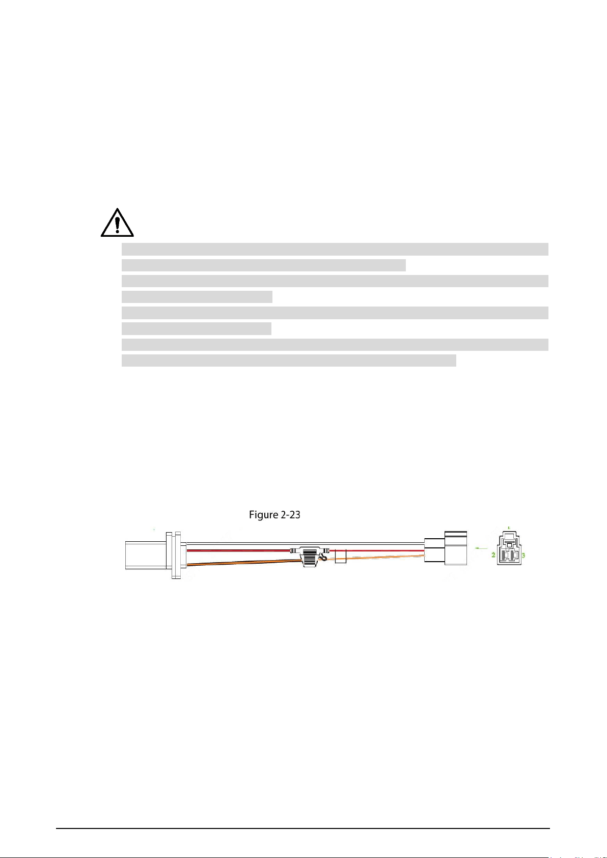
For power cable of the Recorder, see Figure 2-23.
Connect one end of the power cable to the power port of the Recorder or directly use the power
cable from the Recorder. Connect the other end to the vehicle battery.
The red one with fuse is positive pole of the power (normal wire).
The black one is the grounding cable.
The orange one is the ACC signal (key starting wire).
Power cable
2.2.5.1.2 Obtaining Connection Modes
To ensure correct cable connection, it is necessary to obtain the connection mode of the main
power switch through three methods (By connection mode here, it means the main power
switch is connected to the positive or negative pole of the battery).
Consult the vehicle manufacturer the connection modes of the main power switch of the
vehicle.
Measure with a multimeter: Disconnect the main switch, and then measure the voltage
between the vehicle body and the positive pole of the vehicle battery. If the voltage is 12V
or 24V, it means that the main switch disconnects the positive pole. If the voltage is 0V,
then the main switch disconnects the negative pole.
Visual inspection: Whether the switch cable near the vehicle battery is connected to the
positive pole or the negative pole.

25
2.2.5.1.3 Connecting Operation
The Recorder must be connected to the ground wire, ACC signal, and constant electricity.
Enable the main power switch on the vehicle, place the key in the OFF state, and then
measure the normal live electricity of the vehicle.
Use a multimeter to measure the voltage on the fuse by switching to the DC voltage range.
When the multimeter detects voltage, it measures the normal live electricity on the vehicle.
Generally, the voltage is 24V DC for large vehicles and 12V DC for small vehicles. However,
this is subject to actual data.
When the vehicle key is placed at the ACC state or the ON state, the ACC signal of the vehicle
is measured.
Use a multimeter to measure the voltage on the fuse by switching to the DC voltage range.
When the multimeter detects voltage, remove the car key. If the voltage changes to 0V, it
means that the measured signal is ACC on the car.
Turn off the main power switch on the vehicle, and place the key in the OFF state.
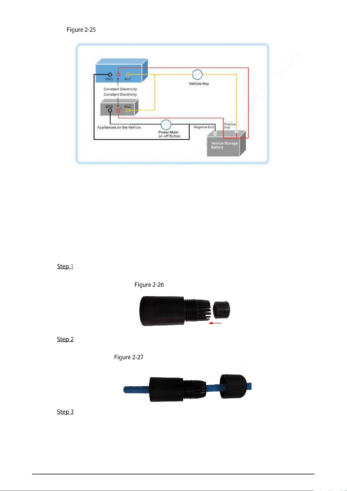
Connect the power cable according to the main power switch installation mode. See Figure
2-24 and Figure 2-25.
Before connecting with power cord, select proper fuse. 7.5A fuse is recommended.
The positive and negative poles of the battery must be equipped with protective
devices such as fuses.
For vehicles where the main power switch is installed at the cathode of the
accumulator, isolation installation is needed.
Vehicle main power switch installed on the positive pole of the vehicle battery
26
Vehicle main switch installed on the negative pole of the vehicle battery
2.2.5.2 Audio and Video Input and Output Connection
This section helps you understand the connection of audio and video input and output when you
need to use this function.
2.2.5.2.1 Audio and Video Input
The video and audio data is input through RJ-45 network port. When connecting cable, the
waterproof connector needs to be installed.
Take out the waterproof connector from the accessory box, and connect the gasket toward
the arrow direction onto the waterproof connector. See Figure 2-26.
Gasket installation
Put the network cable (without Ethernet port) through the main part of waterproof
connector, gasket and encap, and then make the Ethernet plug. See Figure 2-27.
Cabling and Ethernet plug making
Connect the rubber gasket to the Ethernet port. See Figure 2-28.
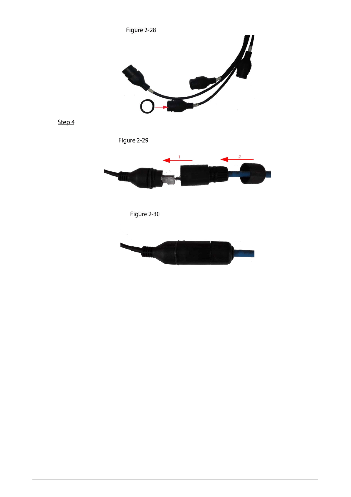
27
Rubber gasket installation
Inset the Ethernet plug into the Ethernet port, and then tighten the waterproof connector.
See Figure 2-29.
Waterproof connector fastening
See Figure 2-30 for the connected waterproof connector.
Connection completed
2.2.5.2.2 Audio and Video Output
Video Output
The Recorder is provided with one CVBS (PAL/NTSC 1.0V
P-P
, 75Ω) port and VGA port, and
supports the simultaneous output from these two ports.
Read the following contents carefully before using the computer instead of monitor.
For VGA output, you need to prepare a VGA adapter cable to connect to computer.
To extend the Device life, do not keep the Device running for a long time.
Regular demagnetizing helps keep the monitor working properly.
Stay away from devices with strong electromagnetic interference.
Audio Output
The audio output signal parameter is larger than 200mv 1KΩ. The audio output port can directly
connect to the display with audio function on the vehicle or active speaker, and the port can
also drive other sound output devices through amplifier.
28
2.2.5.3 Alarm Input and Output Connection
Before using the alarm function, learn about the connections method of alarm input and output
port.
Alarm Input
The alarm input port supports alarm signal from ground and Recorder of 12V-24V voltage.
If the alarm Recorder is connected to the Recorder and other Recorders, use relay for
isolation.
Alarm Output
The alarm output port cannot be connected to high-power load (less than 1A). When
constructing the output circuit, the excessive current should be prevented from causing
damage to the relay. Use the contactor for isolation when applying high-power loads.
No Restriction for Alarm Input Types
The alarm input can be Normally Open (NO) or Normally Closed (NC).
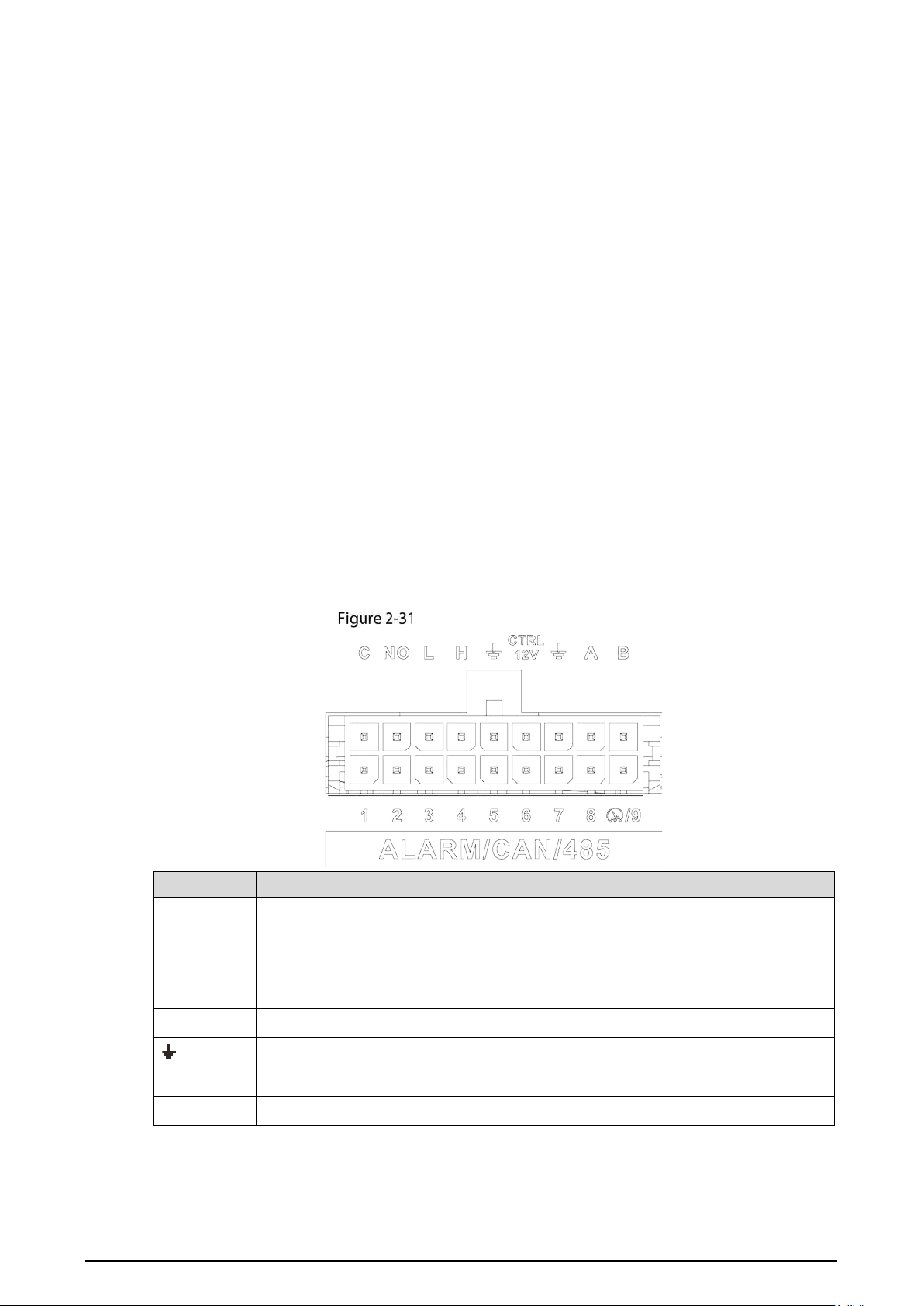
2.2.5.3.1 Port Definition
Alarm input/output port
Name
Function
1–9
Alarm input 1–9, where 1–8 are local alarm input, 9 is a combination of impulse
and alarm (but only one function, impulse or alarm, can be used).
C, NO
Outputs alarm signal to alarm device.
"NO" represents normally open type.
C: Common alarm output port.
L, H CAN port.
Ground line.
CTRL 12V 12V/0.75A output with switch control.
A, B RS-485 port that connects to speed dome with PTZ function.
2.2.5.3.2 Alarm Input Port
Both NO and NC are supported.
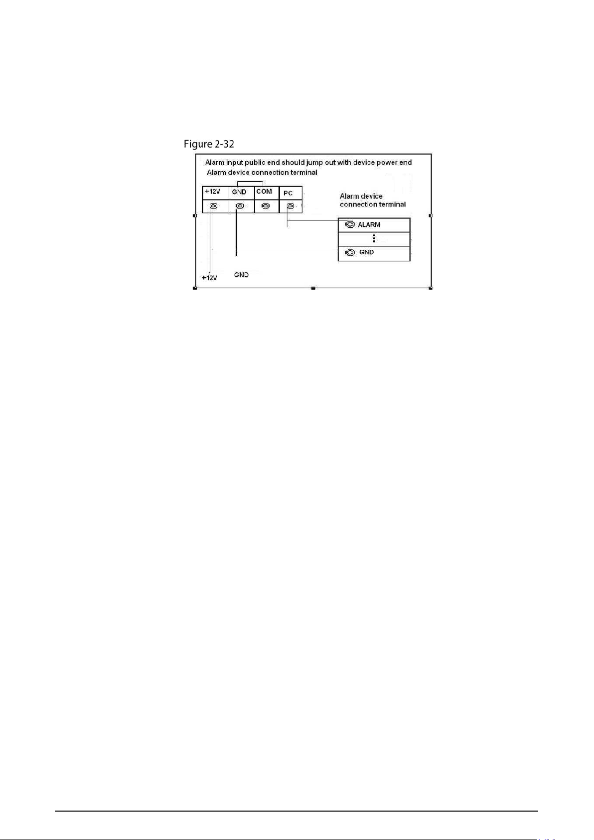
29
The GND of alarm detector is in parallel connection with COM (the power supply of alarm
detector should be from external power source). See Figure 2-32.
The GND of alarm detector is in parallel connection with GND of Recorder.
Connect the NC port of alarm detector to the alarm input port (ALARM).
When supplying power from external power source to the alarm Recorder, the alarm
Recorder should be common-grounded with the Recorder.
Normally Closed alarm input illustration

30
3 Basic Settings
This Recorder can be operated following instructions on the local interface or web interface. This
section introduces the web interface instructions. The Local interface is similar and would not be
elaborated here.
Browsers including Safari, Firefox, and IE are supported.
Booting up Recorder
Before booting up the Recorder, check if input voltage matches rated voltage of the Recorder.
Refer to international standard to offer the power input (power input that is with stable power
value and less interference) to ensure the Recorder works stably and prolong its service life.
In the first power-on, the Recorder needs connection to the ACC to work as intended.
Rotate the Recorder key to and rotate the vehicle key to ACC position. The power indicator is on,
and the Recorder is ready for work.
For the first boot up or after restoring to the default factory settings, the initialization interface is
displayed on the screen. Follow on-screen instructions to initialize your Recorder prior to use.
Initializing Recorder
When you are opening the Recorder for the first time or you have allowed your system to be restored
the factory settings, you need to initialize the Recorder. Only after that can you operate and
configure your Recorder.
Preparation
Please make sure the correct network connection between PC and the Recorder.
Procedure
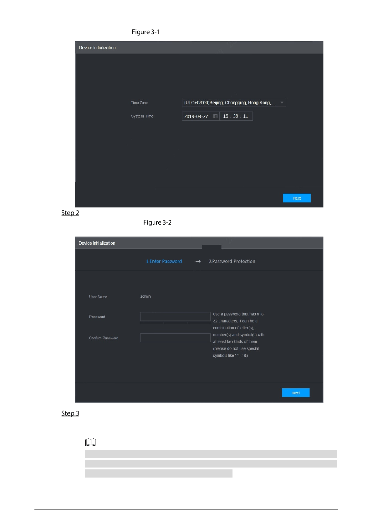
Open the browser, enter the Recorder IP address (the default IP address is 192.168.1.108),
and then press Enter.
The Device Initialization interface is displayed.
31
Device initialization interface
Select Time Zone and System Time. Then click Next.
Password protection
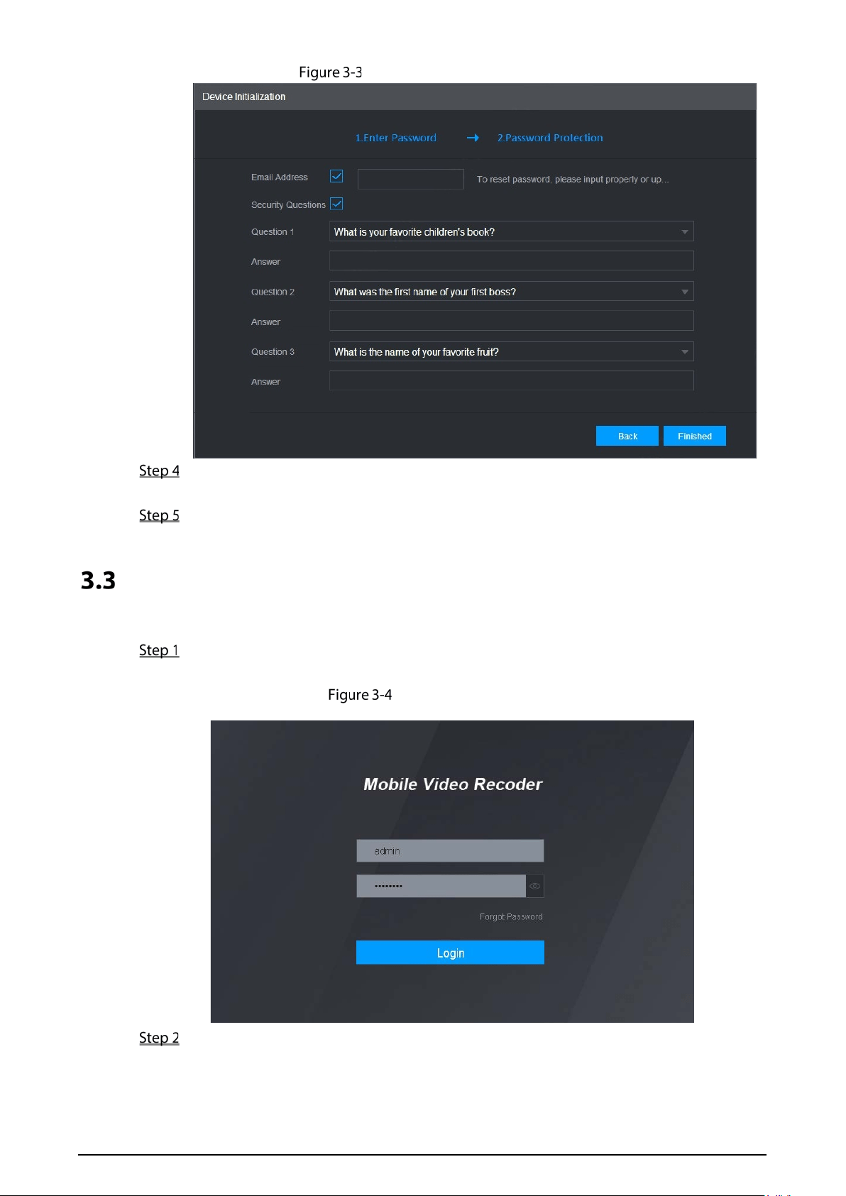
Enter your password and enter it again to confirm it. Then click Next.
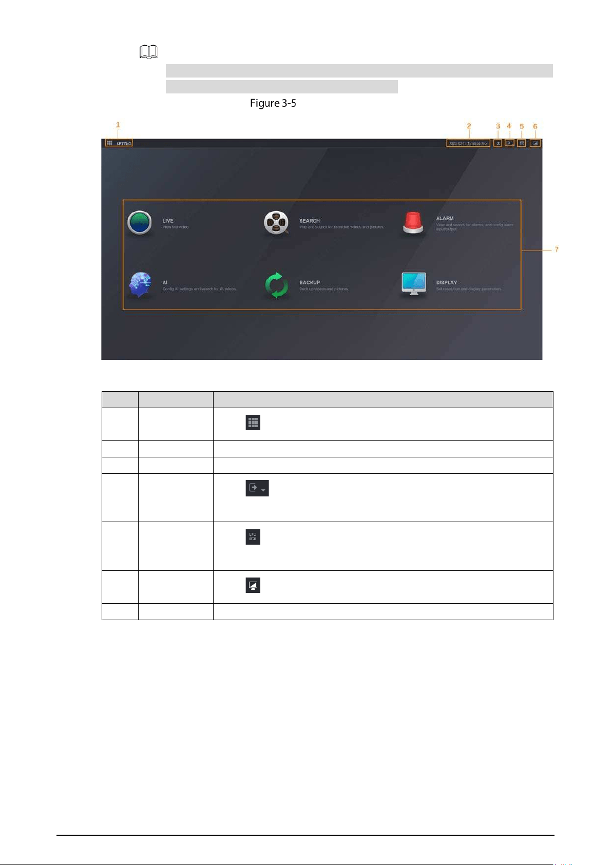
Then an interface is displayed to let you fill in the password protection settings. See Figure
3-3.
You are recommended to use strong password. The password must consist of 8 to 32
non-blank characters and contain at least two types of characters among upper case, lower
case, number, and special character (excluding ' " ; : &).
32
Password protection settings
You are recommended to fill in the email address and answer the password protection
questions.
Click Finished.
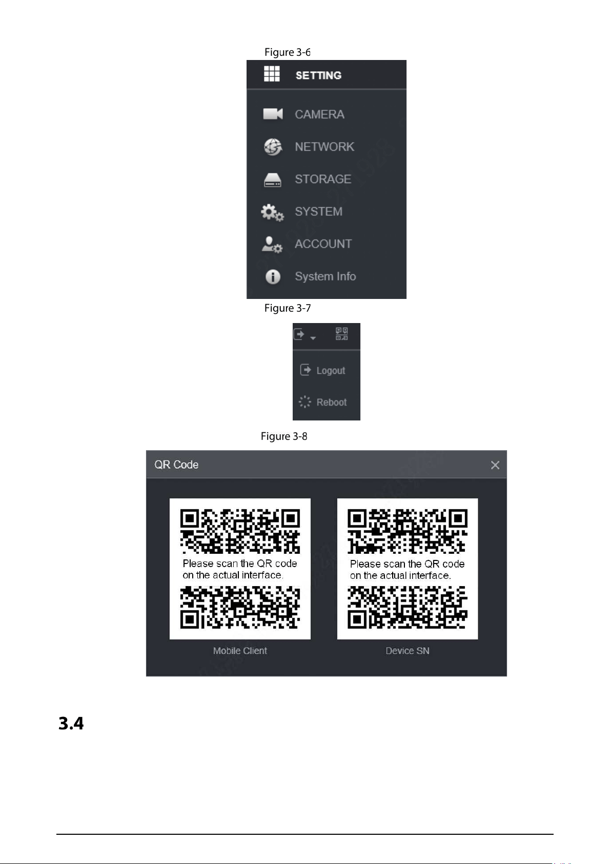
Logging in to Recorder
You can log in to and then configure the Recorder.
Open the browser, enter the Recorder IP address, and then press Enter.
The Login interface appears. See Figure 3-4.
Web login interface
Enter username and password, and click Login.
The web interface is displayed.
33
For admin account, if you forget password, click Forgot password to find back the
password. For details, see "5.9.4Resetting Password".
WEB interface
Table 3-1 Description of WEB interface
No. Name Description
1 SETTING
Click or Setting. See Figure 3-5.
2 Time Display the current time.
3 User Display the user that currently logs in.
4 Logout
Click , the system displays as Figure 3-7. Select Logout or Restart
as needed.
5 QR Code
Click , the system displays as Figure 3-8. Scan device serial number to
add the device to APP.
6 Desktop
Click to return to WEB main interface.
7 Operation System operation
34
Setting
Logout
QR Code
Configuring IP Address
Connect the Recorder to the network and make sure the Recorder can communicate with other
Recorders in the network diagram.
35
Preparation
Make sure the Recorder is connected to the network properly.
Procedure
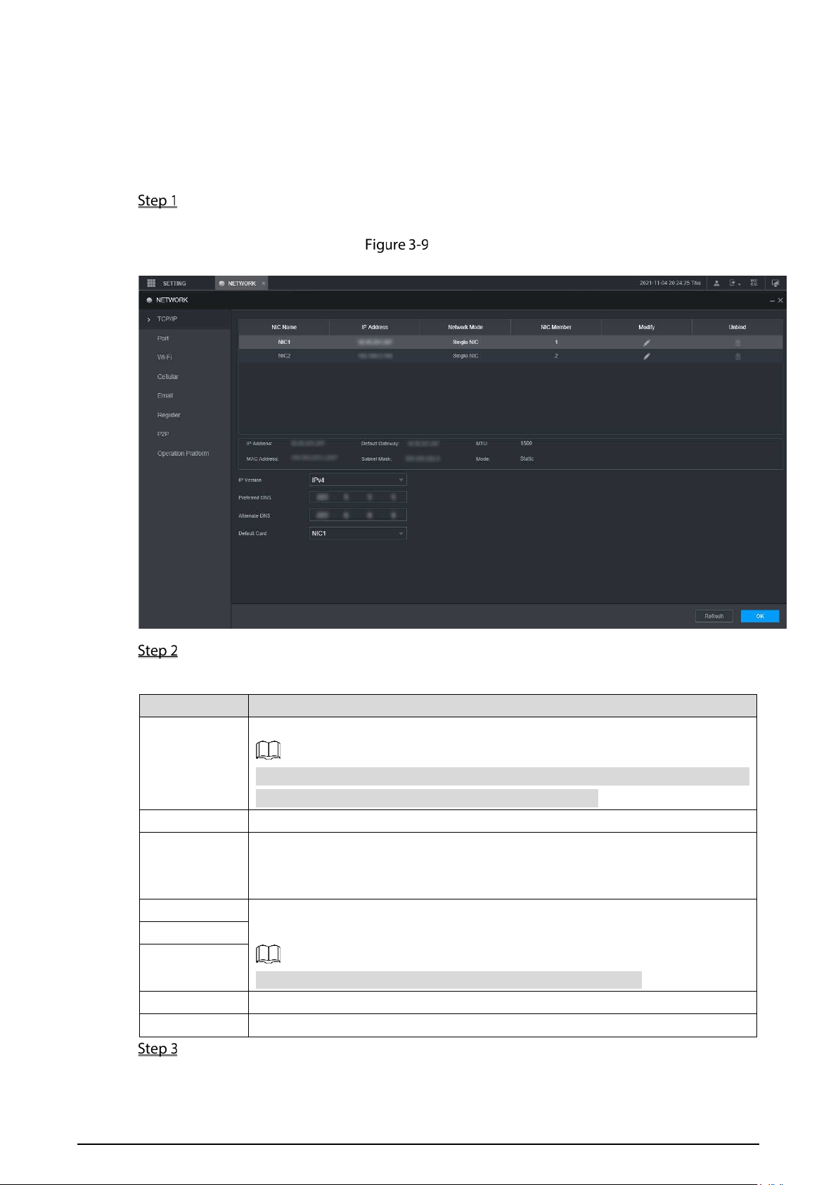
Select SETTING > NETWORK > TCP/IP.
The TCP/IP interface is displayed. See Figure 3-9.
TCP/IP
Configure serial port parameters. See Table 3-2.
Table 3-2 Network settings
Parameter Description
IP Version
Click IPv4 or IPv6. Both versions are supported.
For IPv6 version, in the IP address box, Gateway box, Preferred DNS box, and
Alternate DNS box, enter 128 bits and cannot be blank.
MAC address Host's MAC address, cannot be modified.
DHCP
Obtains IP address automatically. With DHCP enabled, IP Address, Subnet Mask
and Default Gateway cannot be configured. You can check the current IP
address whether the DHCP takes effect or not.
IP address According to your network plan, enter the modified IP address, gateway and
subnet mask.
IP address and gateway must be in the same network segment.
Subnet Mask
Default
gateway
Preferred DNS IP address of the preferred DNS
Alternate DNS IP address of the alternate DNS
Click OK.
36
Configuring General Settings
You can configure the basic settings, including time and date settings.
3.5.1 Setting General Information
Set the general information of the Recorder, including video recording strategy when the Disk is full,
recording length, menu standby duration, license plate, and more.
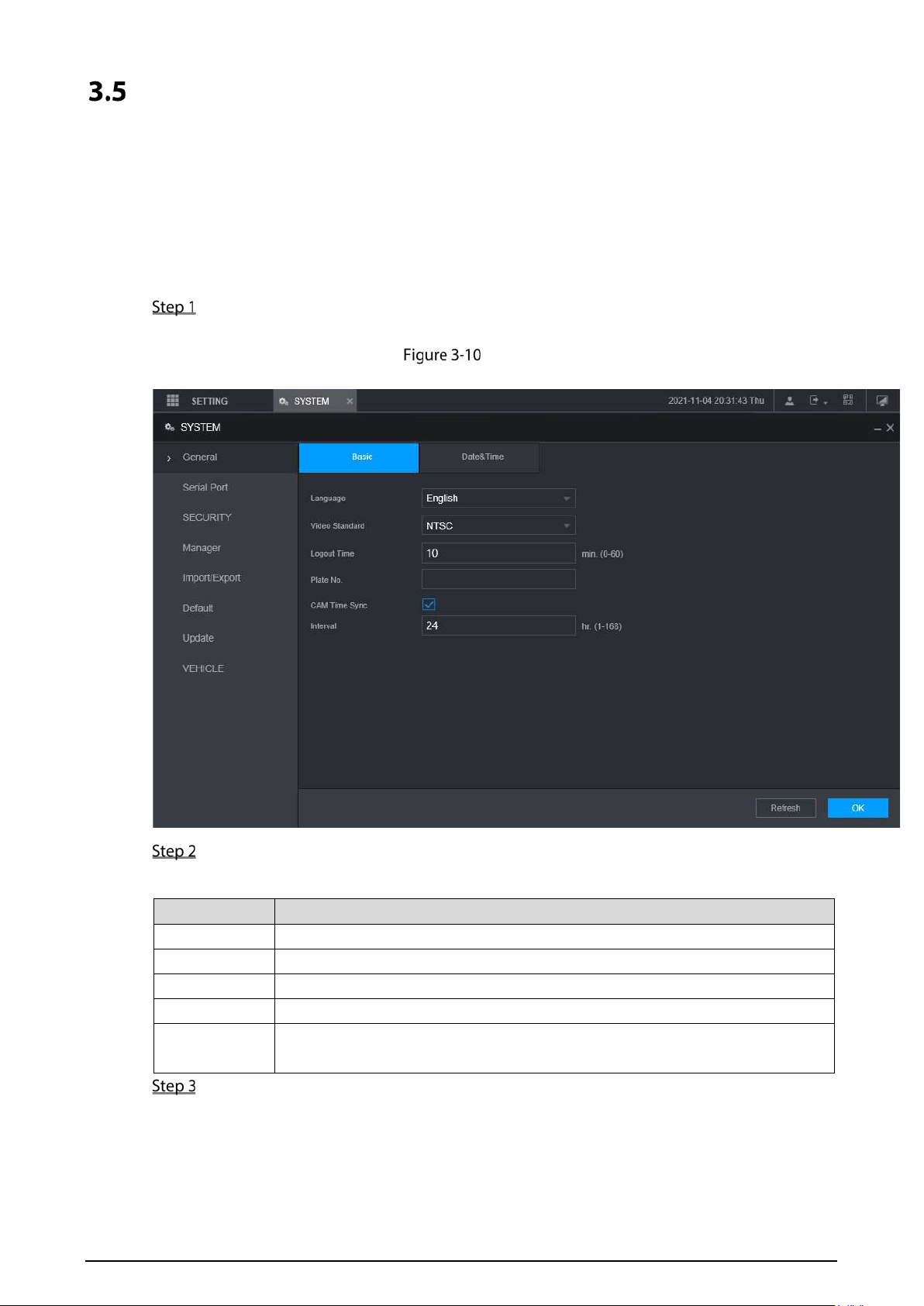
Select SETTING > SYSTEM > General > Basic.
The Basic interface is displayed. See Figure 3-10.
Basic
Configure more settings.
Table 3-3 General settings parameters description
Parameter Description
Language Select a language for the Recorder system.
Video Standard Displays the video encode standard.
Logout Time Configure time from 0 min to 60 min.
Plate No. Enter the license plate number of vehicle where the Recorder is located.
CAM Time Sync
You can click the CAM Time Sync check box and enter the interval for camera
sync with the Recorder.
Click OK.
3.5.2 Date and Time Settings
You can configure settings such as date format, time format, and timing mode.
37
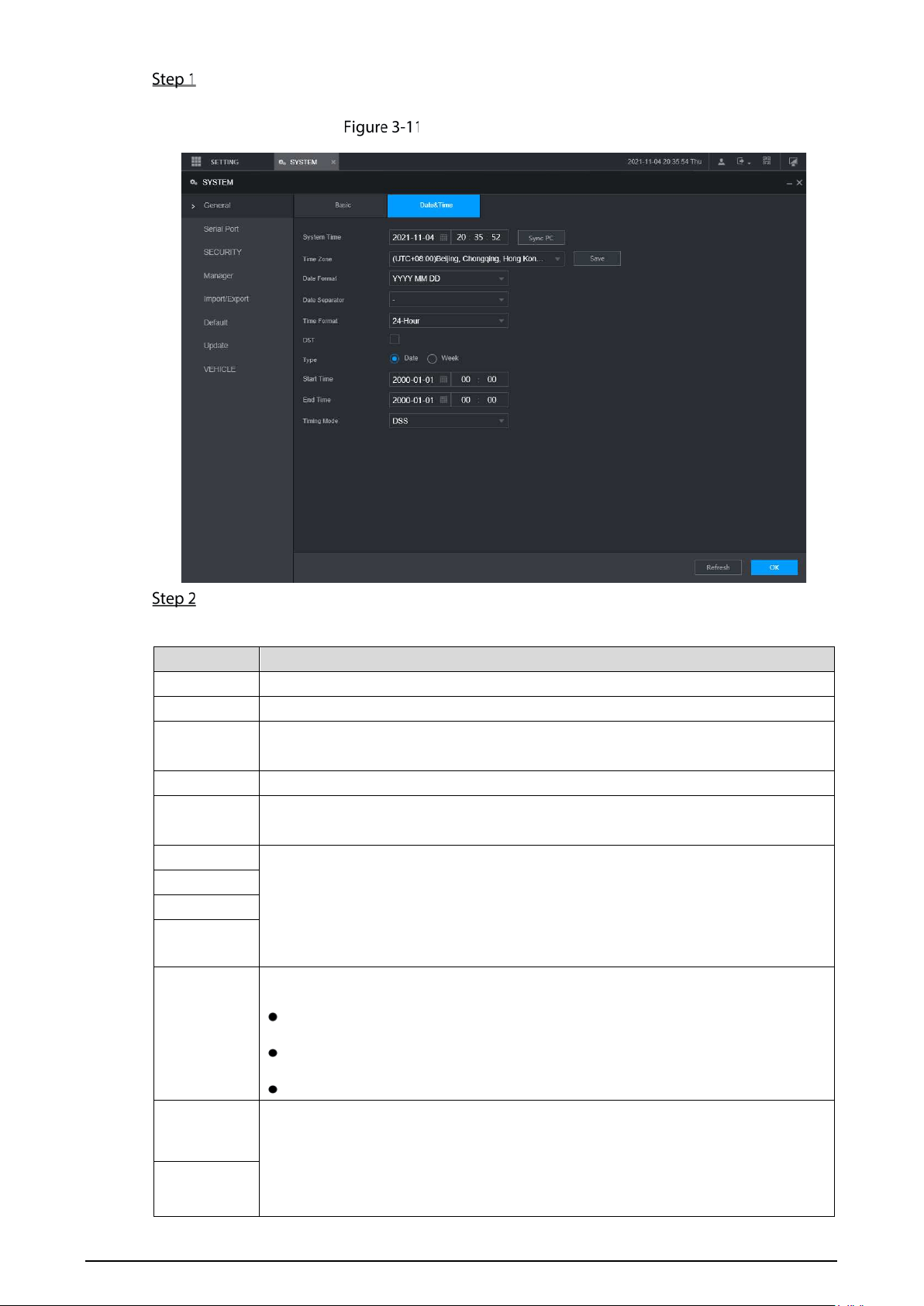
Select SETTING > SYSTEM > General > Date & Time.
The Date & Time interface is displayed. See Figure 3-11.
Date and time settings
Configure Serial port parameters. See Table 3-4.
Table 3-4 Date and time settings parameters description
Parameter Description
Date format Select a date format.
Time format Select a time format.
Time zone
In the Timing Mode list, if GPS or NTP is selected, configure this parameter.
Configure the Time zone that the Recorder is at.
System Time Displays the current system date and time.
Sync PC
Click Sync PC to sync the system time with the PC from where you login the web
interface.
DST
The DST is applied in some countries or regions. Select the DST check box if it is
applied where the Recorder is located
1. Click the DST check box.
2. According to the local regulations, configure the type, begin time and end
time for the DST.
DST Type
Start Time
End Time
Timing
Mode
Select a timing mode, including DSS, GPS, and NTP. The default selection is NTP
DSS: The system time syncs with DSS platform.
GPS: The system time syncs with satellite.
NTP: The system time syncs with NTP server that you configured.
Server
Address
In the Timing Mode list, if NTP is selected, configure this parameter.
After configuring NTP server, the Recorder syncs time with NTP server.
3. In the Timing Mode list, select NTP to enable the NTP timing function.
4. Configure parameters.
Manual
Update
38
Port
Server Address: Enter IP address of NTP server.
Manual Update: Click Manual Update to sync the Recorder time with
NTP server.
Port: The system supports TCP protocol only and the default setting is
123.
Interval: Enter the interval that you want the Recorder to sync time with
the NTP server. The maximum value is 65535 minutes.
Interval
Click OK.
Configuring Remote Recorders
This section describes how to add cameras to channels. Connect the IPC to the Ethernet port on the
rear panel of the Recorder. You can use a holder or tie strap to fix the port.
3.6.1 Initializing the Remote Recorder
Only the initialized remote Recorder can be added. If the remote Recorder that you want to add has
been initialized, ignore this section.
Preparation
Make sure the remote Recorder supports initialization.
Procedure
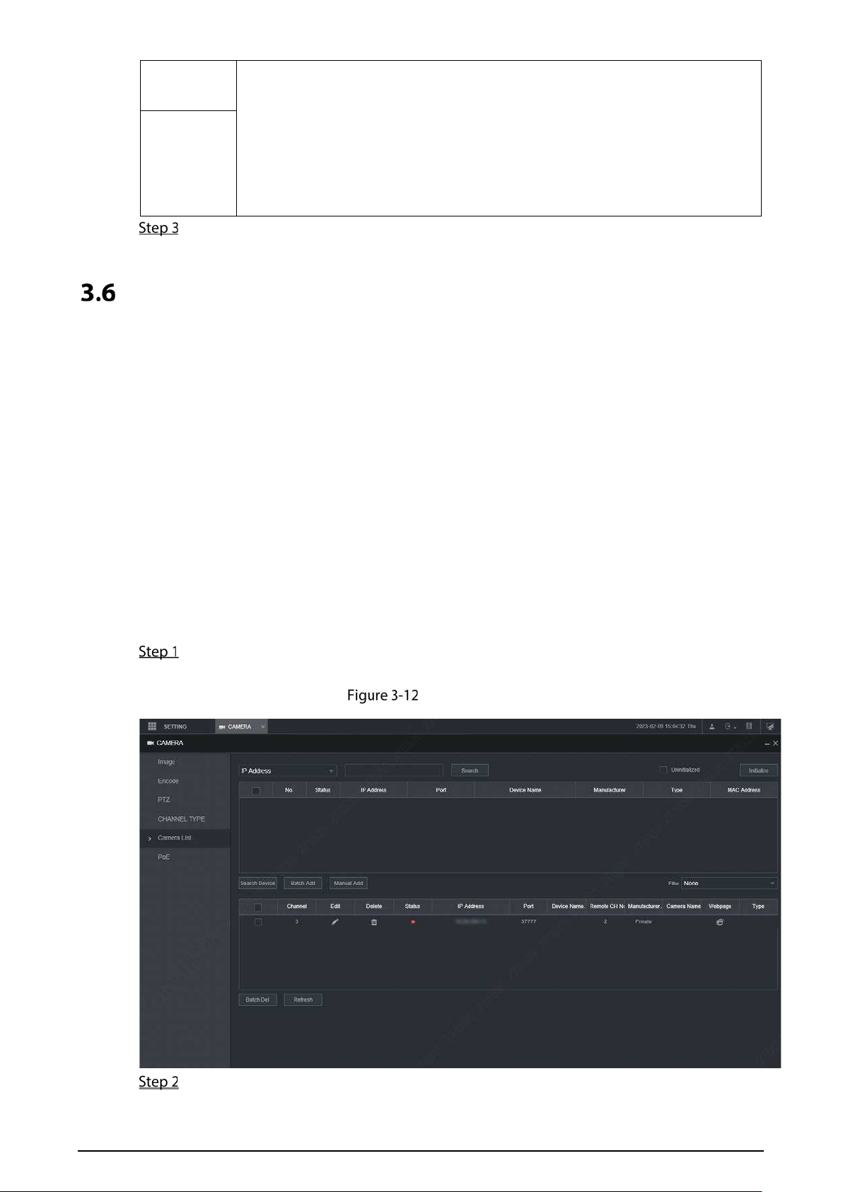
Select SETTING > CAMERA > Camera List.
The Camera List interface is displayed. See Figure 3-12.
Camera List
Click Search.

39
The searched recorders are displayed.
Click the Uninitialized check box.
The uninitialized recorders are displayed.
Click the check box the uninitialized Recorder, and then click Initialize.
The Enter Password interface is displayed. See Figure 3-13.
Enter password interface
Configure the password by either of the following two ways.
Using current Recorder password and email info. Select the Using current device password
and Email check box, and the remote Recorder uses the password and email info of the
Recorder.
Manually configure password for remote Recorders.
1) Clear the Using Current Recorder password and Email check box.
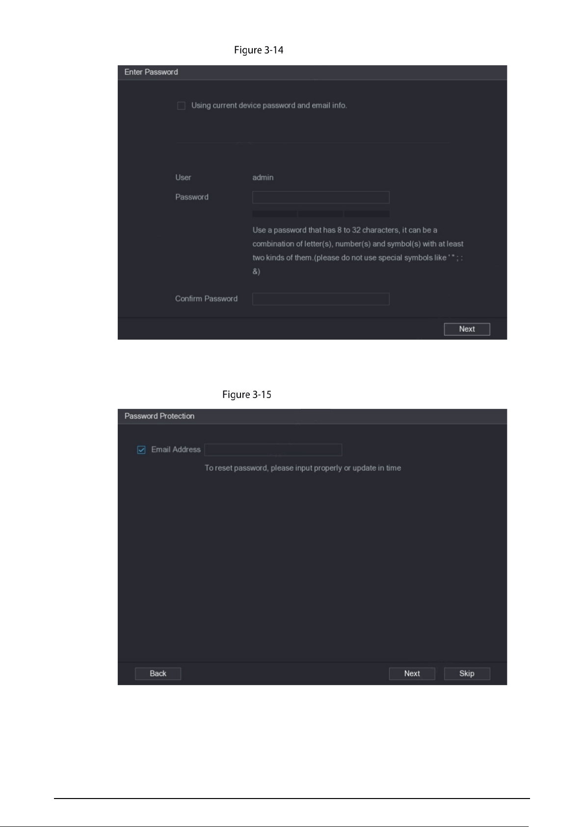
The password setting interface is displayed. See Figure 3-14.
40
Set a password
2) In the Password box, enter the new password and enter it again in the Confirm
Password box. Click Next.
The password setting interface is displayed. See Figure 3-15.
Password protection
3) Set password protection.
Click the Email Address check box, and then enter the email address. Click Next.
Click Skip if you do not want to set up password protection.
The Modify IP interface is displayed.
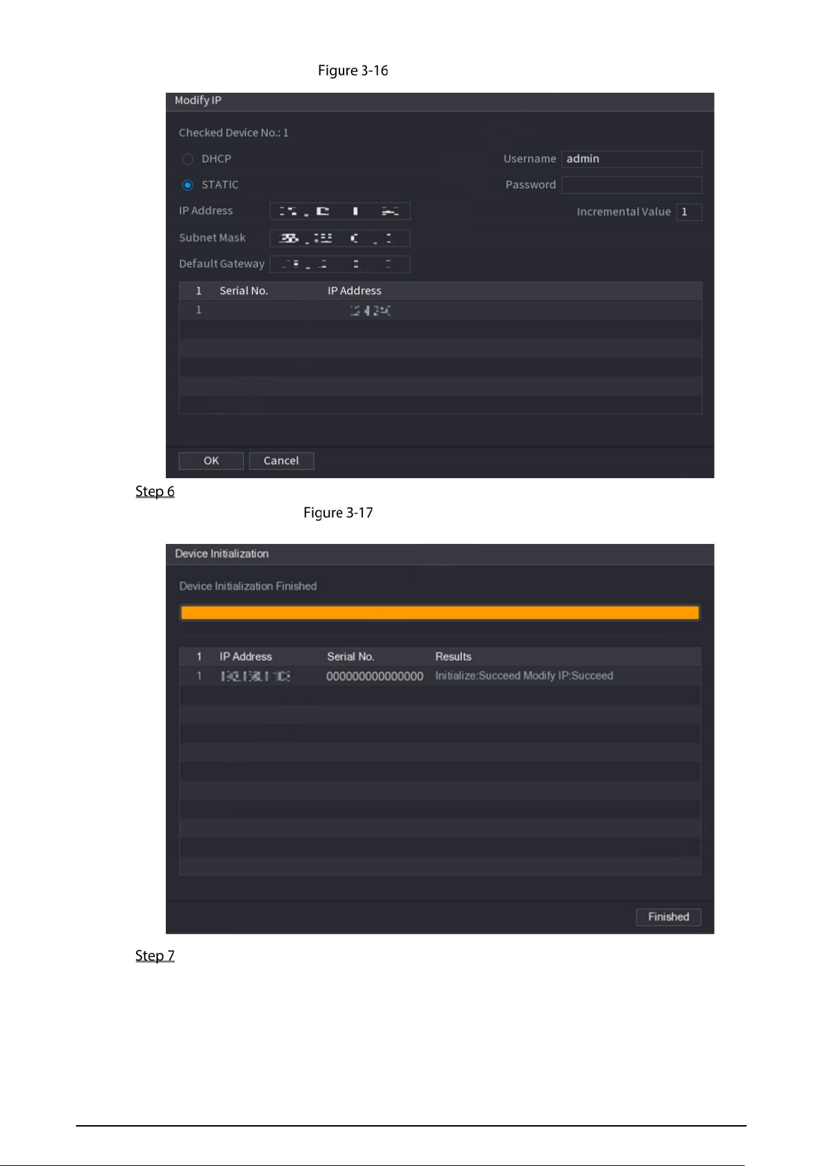
42
Select SETTING > CAMERA > Camera List.
The Camera List interface is displayed.
Adding a remote recorder.
Search and Add
1. Click Search, the searched Recorders are displayed.
2. Double-click on an IP address or select the check box of a Recorder, and then click
Add.
The Recorder displays in the added Recorder area.
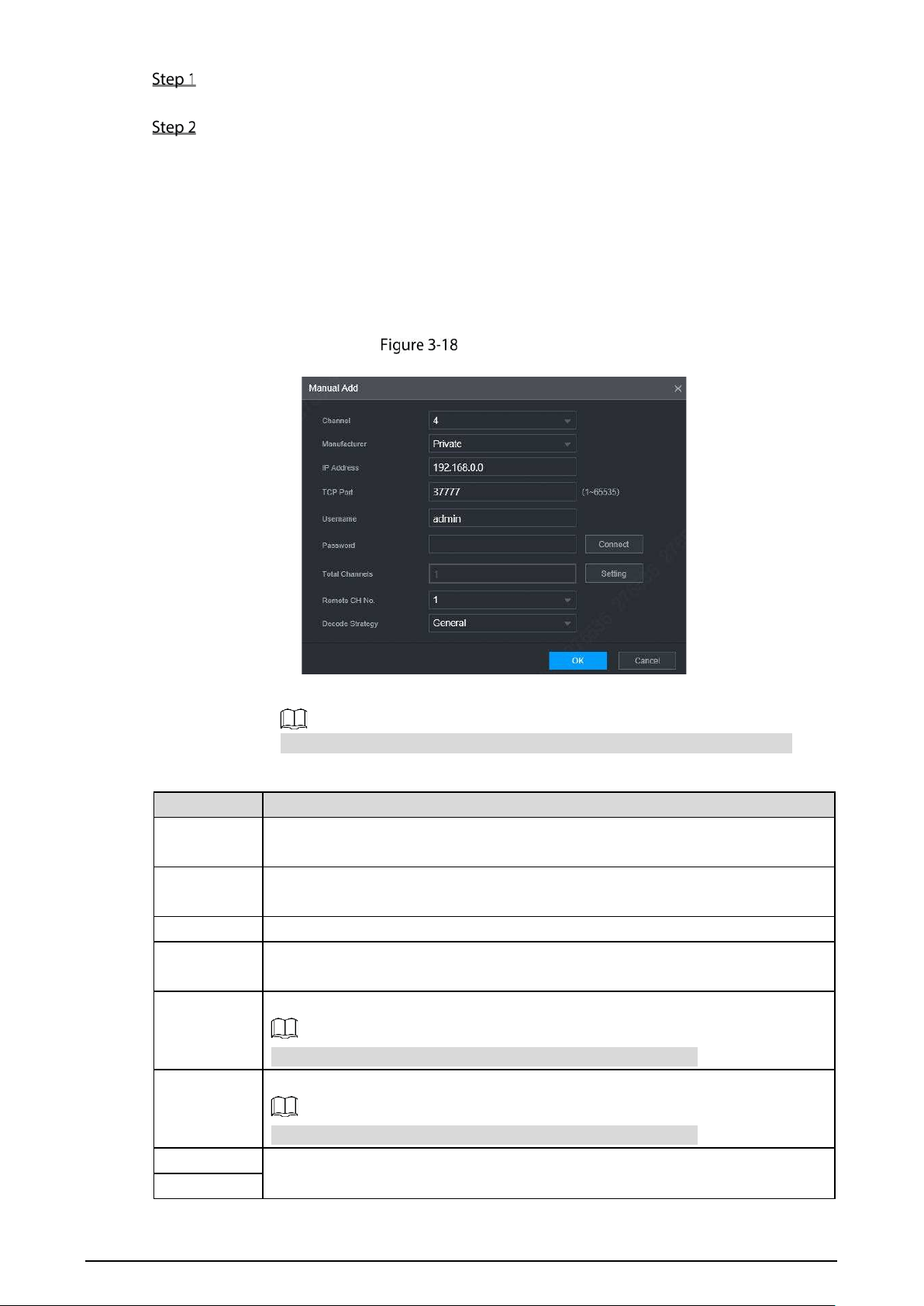
Manual Add
1. Click Manual Add.
The Manual Add interface is displayed. See Figure 3-18.
Manual add
2. Configure more settings. See Table 3-5.
The parameters might be different depending on the model you purchased.
Table 3-5 Manual add parameters description
Parameter Description
Channel
The channel number of the remotely connected device. You can only select a
channel that has not added remote devices.
Manufacturer
Select a manufacturer according to the actual situation. Parameters might vary by
manufacture. Follow specific parameters on the interface.
IP address Enter the IP address of remote Recorder.
TCP Port
TCP service port. The default setting is 37777. You can configure this parameter
according to your actual situation.
RTSP Port
Enter RTSP Port number of remote Recorder. The default setting is 554.
This must be set up when you select Onvif as the Manufacturer.
HTTP Port
Enter HTTP Port number of remote Recorder. The default setting is 80.
This must be set up when you select Onvif as the Manufacturer.
Username
Enter the user name and password to login to the remote Recorder
Password

43
Remote
Channel
Select the channel number that you want to connect.
Decode
Strategy
Select decode strategy from real-time, normal and fluent.
Encryption
Select “Encryption” and the system will encrypt and protect the transmitted data.
This must be set up when you select Onvif as the Manufacturer.
This function requires the IPC to enable HTTPS.
Service type
This must be set up when you select Onvif or Custom as the Manufacturer
When selecting different manufacturers, the service types are different. Select the
service type based on your needs.
3. Click OK.
The Recorder displays in the added Recorder area.
If the remote Recorder that you want to add has the same IP address and
TCP port with the existing added Recorder, then this Recorder cannot be
added.
indicates connection is successful; indicates connection failed.
To delete an added Recorder, select it, and then click Delete; to modify the
information of an added Recorder, click or double-click the Recorder.
3.6.3 Modifying IP Address of Remote Recorder
You can modify the IP address of remote Recorder according to your network plan.
Select SETTING > CAMERA > Camera List.
The Camera List interface is displayed.
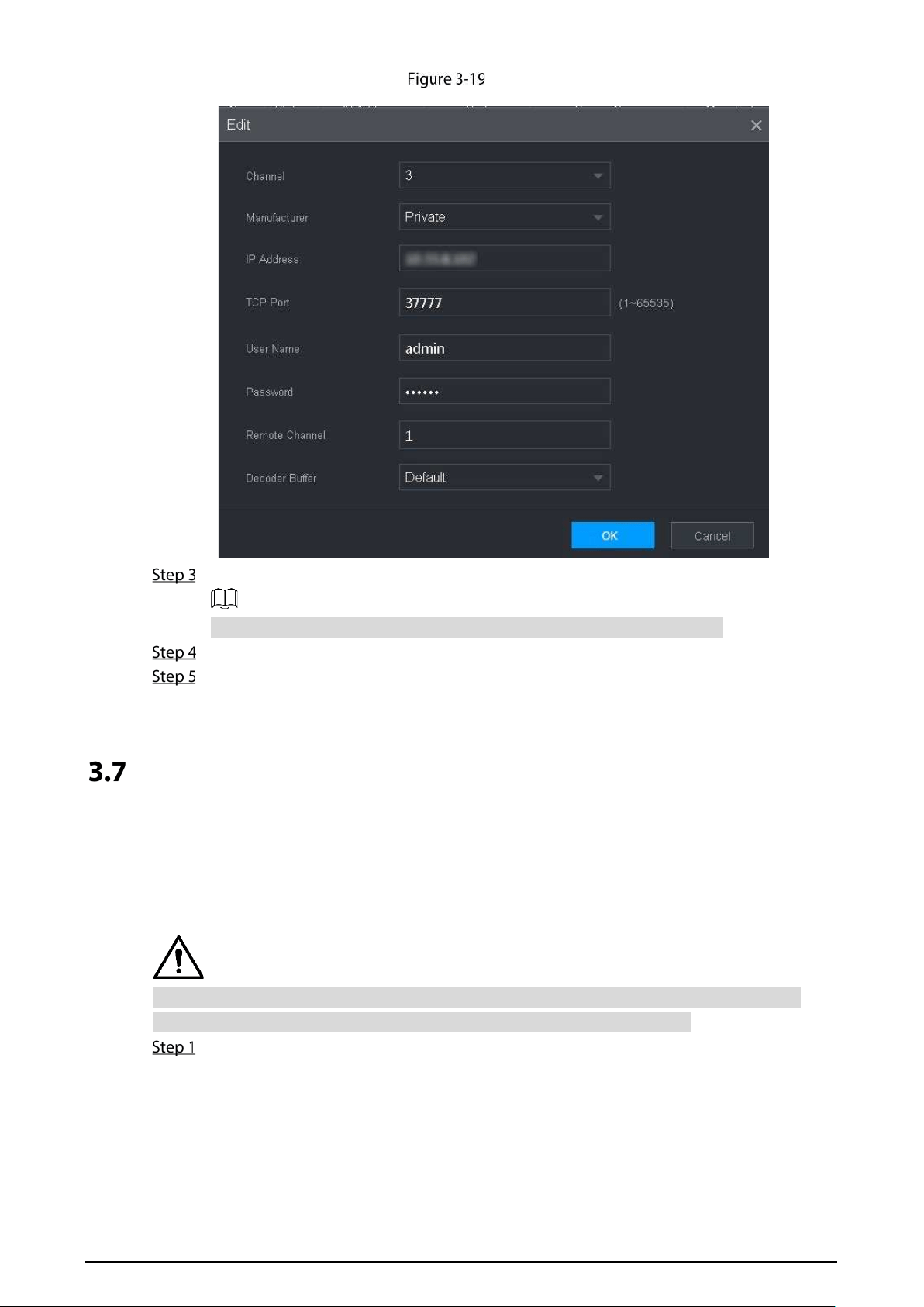
In the Added Recorder list, click corresponding to a Recorder.
The Edit interface is displayed. See Figure 3-19.
44
Edit
Enter the user name and password of remote Recorder.
The system automatically obtains the user name, which is admin by default.
Enter the IP address of remote Recorder according to your network plan.
Click OK.
After modification, the new IP address is displayed in the added Recorder area.
Configuring Record
The record mode is consisted of manual mode and auto mode. You can also enable or disable the
snapshot function.
Auto: The recording starts automatically according to the record type and recording time as
configured in the recording schedule.
Manual: Keep general recording for 24 hours for the selected channel.
Manual recording operation requires the user have the permission to access STORAGE settings.
Check to ensure the HDD installed in the Recorder has been formatted properly.
Select SETTING > STORAGE > Record Mode.
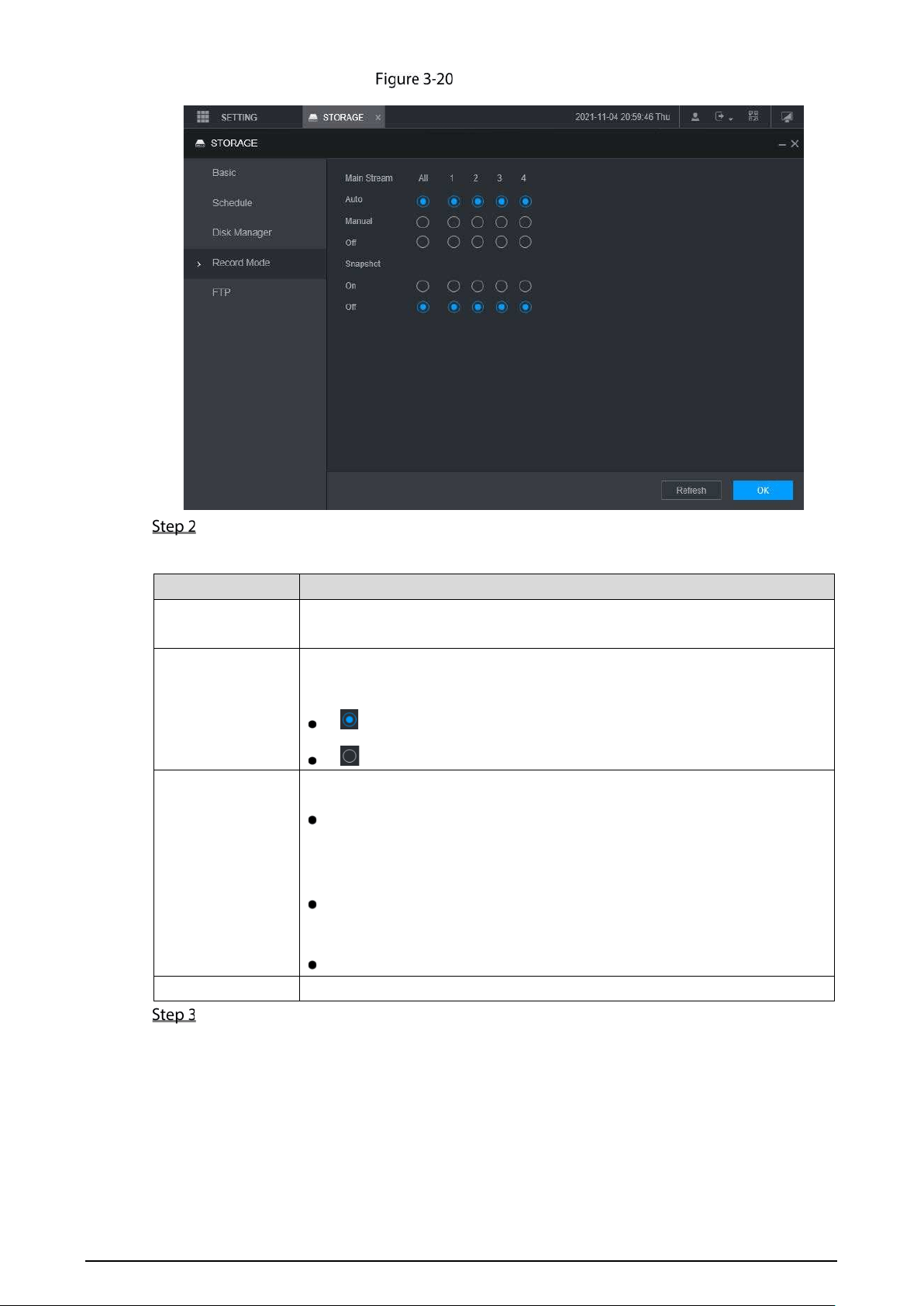
The Record Mode interface is displayed. See Figure 3-20.
45
Record Mode
Configure Serial port parameters, for the detailed description, see Table 3-6.
Table 3-6 Record Mode parameter description
Parameter Description
Channel
Displays the channel number.
You can select one or several channels or select All.
Status
Indicates the recording status of corresponding channels. The choices
include Auto, Manual, Enable, and Stop.
: Selected
: Not selected
Auto/Manual/Off
Select the recording mode, including Manual, Auto, and Stop.
Manual: Top priority. When the Manual
check box is selected, the
system keeps general recording for 24 hours for the corresponding
channel.
Auto: The system starts recording according to the record type (such as
general alarm, motion detect, and system alarm) and recording time.
Off: Do not record.
Enable/Off Enable or disable the scheduled snapshot for the corresponding channels.
Click OK.
46
Storage Plan
3.8.1 Configuring Recording Schedule
All channels record 24 hours by default. You can configure the record type and recording time as
needed.
Preparation
The auto recording function is enabled for the corresponding channel. For details, see "3.7
Configuring Record."
Procedure
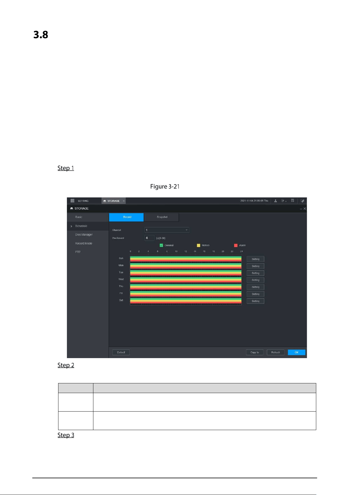
Select SETTING > STORAGE > Schedule > Record.
The Record interface is displayed. See Figure 3-21.
Record
Configure pre-record parameters. See Table 3-7.
Table 3-7 Pre-record parameters description
Parameter Description
Channel
Select a channel to configure the corresponding recording schedule. If you
configure the same setting for all channels, select All.
Pre-record
Start recording from 0s to 30s before the alarm event occurs. If you enter 0 seconds,
there will be no pre-recording.
Configure the recording time period.
1) Click Setting corresponding to the weekday.
The Period interface is displayed. See Figure 3-22.
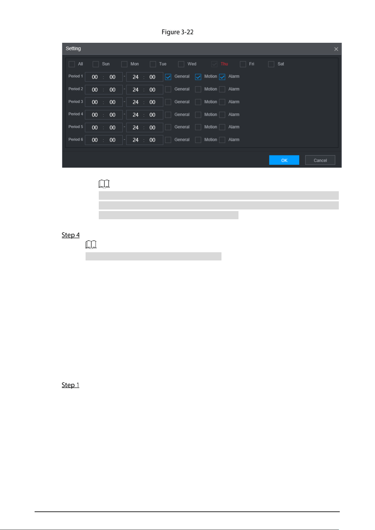
47
Period
2) Select the record type and a weekday, and configure the period.
If the Motion check box and the Alarm check box are selected, the corresponding
alarm linkage should be enabled. For example, if the alarm type is Motion, select
Enable Channel, and select the recording channel.
3) Click OK to return to the Record interface.
Click OK.
Click Copy to copy the settings to other channels.
3.8.2 Configuring Snapshot Schedule
You can configure the storage schedule for taking the snapshot.
Preparation
The snapshot function is enabled for the corresponding channel. For details, see "3.7 Configuring
Record."
Procedure
Select SETTING > STORAGE > Schedule > Snapshot.
The Snapshot interface is displayed. See Figure 3-23.
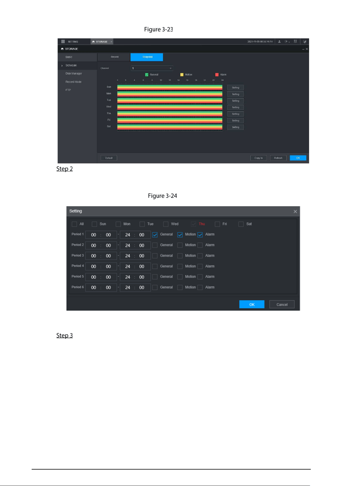
49
4 Function Modules Operations
Operate the Recorder on local interface or web interface. Two kinds of interface operation are
similar. This section takes web interface operation for example.
Live
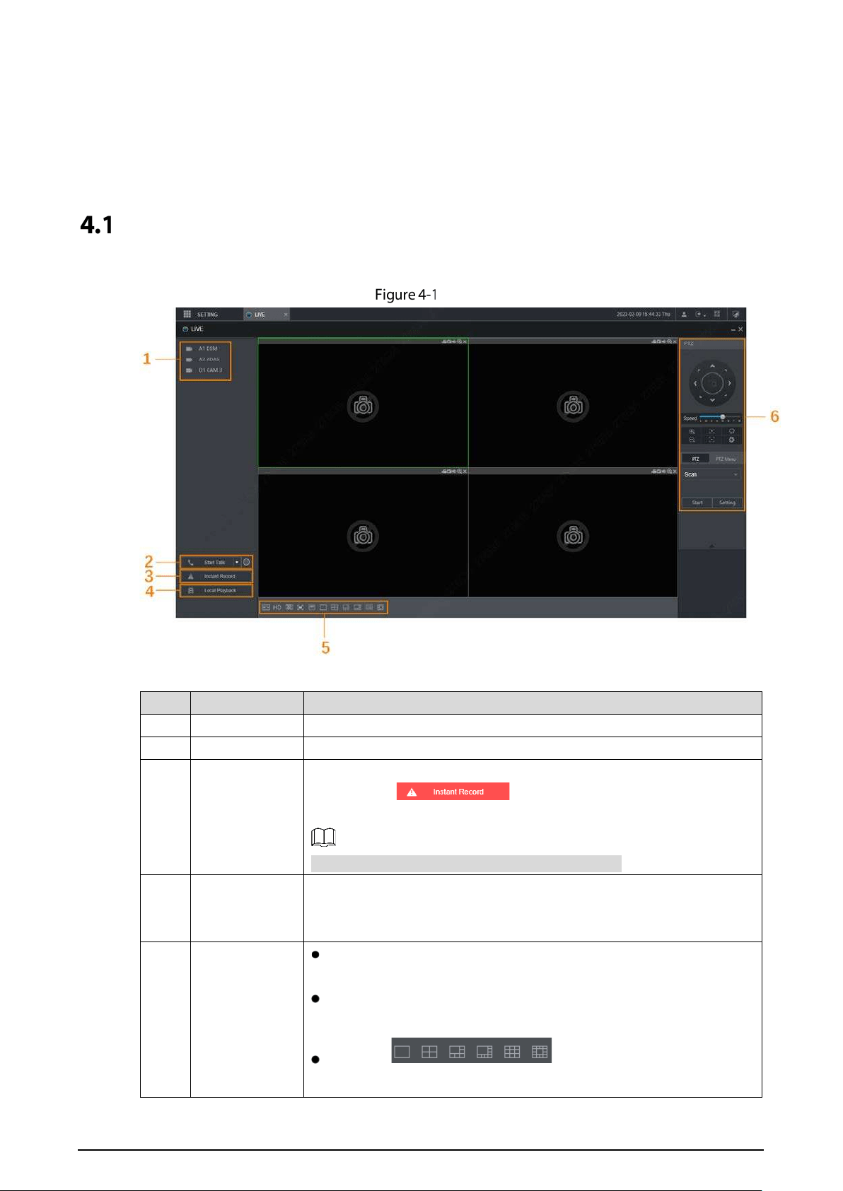
After you logged in to the web interface, the LIVE interface is displayed.
Live
Table 4-1 Live interface parameters description
No. Name Description
1 Live channels See "4.1.1 Live Channels."
2 Start Talk See "4.1.2 Voice Talk."
3
Instant
Recording
Click Instant Record, the recording type switches to Manual, and the
icon turns to ; click Instant Record again to switch
the record type back to Auto.
This function is only supported by main stream.
4 Local Playback
Plays back the video file (.dav) stored on the PC.
Click Local Playback, select the video file in the pop-up dialog box, and
then click Open to start playing back the video file
5
Window
function
operations
Configure the image quality, playback fluency, full screen,
vertical sync, and window split mode.
For real-time monitoring, you can select the fluency or real-time
to be the priority according to your actual requirement.
Select to split the live
window as
necessary.
50
6 PTZ See "4.1.3 PTZ Control."
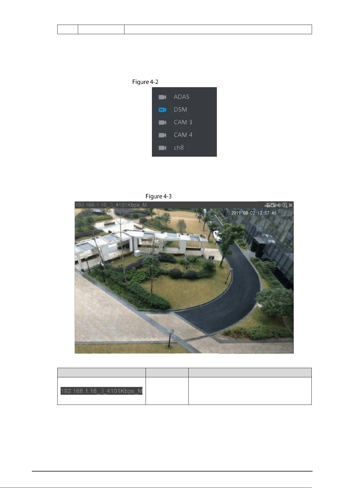
4.1.1 Live Channels
Display the list of monitoring channels.
Monitoring channels
Operations in Monitoring Channels
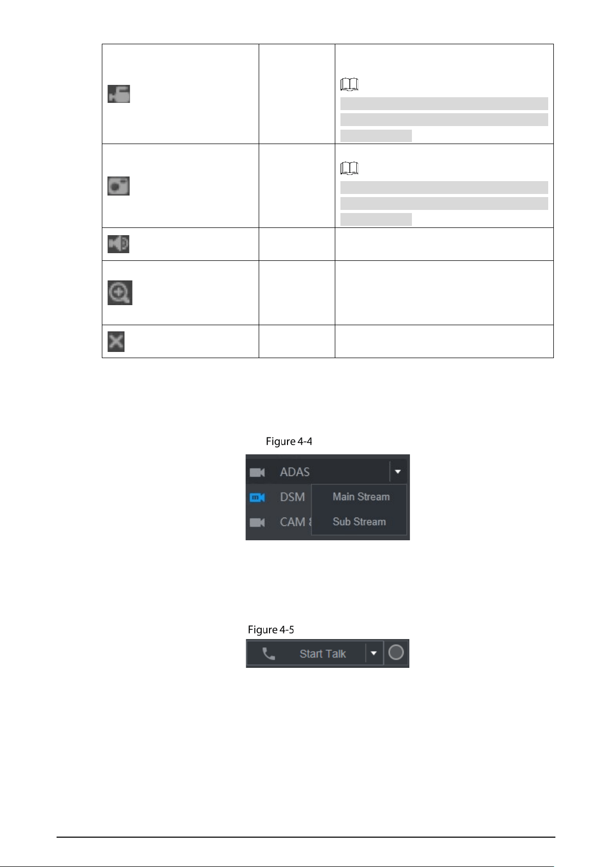
Click any monitoring channel to display its live video. See Figure 4-3.
Live video
Table 4-2 Video monitoring window parameters description
No.
Parameter
Description
Recorder
information
Displays the IP address, channel number, bit
stream, and stream type (M represents main
stream; S represents sub stream)
51
Local Record
Click this icon to start recording; click it again
to stop recording.
The recorded files are stored in C:\Record
Download by default. You can modify this
path if needed.
Snapshot
Click this icon to start taking snapshot.
The snapshots default storage path is
C:\
PictureDownload. You can modify this
path if needed.
Audio Mute/unmute audio.
Area zoom in
Click the icon, and then draw a box at any area
to zoom in the selected part. Right-click or
click the icon again to restore to the original
status.
Close Close the live view in the window.
Bit Rate
The system supports switching between main stream and sub stream in real-time monitoring
window. See Figure 4-4.
Bit rate
4.1.2 Voice Talk
You can do the two-way voice talk between the Device and Client.
Voice intercom
Click Start Talk to enable the voice talk between the Device and Client.
Click the drop-down list to select the voice talk mode. Available options include: DEFAULT,
PCM, G711a, and G711u.
After enabling voice talk, the Start Talk icon turns to End Talk. Click Stop Talk if you want to
end the talk.
52
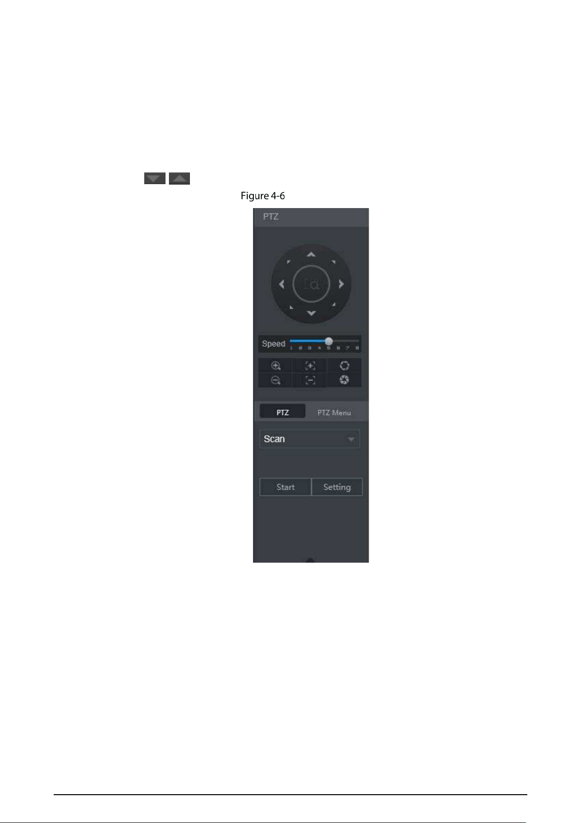
4.1.3 PTZ Control
You can perform the operations through PTZ control panel, such as PTZ directions, speed,
zoom, focus, and iris. See Figure 4-6.
PTZ support rotating Recorder toward eight directions, up, down. Left, right, left up, right
up, left down, right down.
Speed function controls the movement speed. The larger the value is, the faster the PTZ
moves.
Click / to display or hide the PTZ settings and PTZ menu functions.
PTZ Console
4.1.3.2 PTZ
You can configure scan, preset, tour, pattern, and auxiliary functions. For details, see Figure 4-7
and Table 4-3.
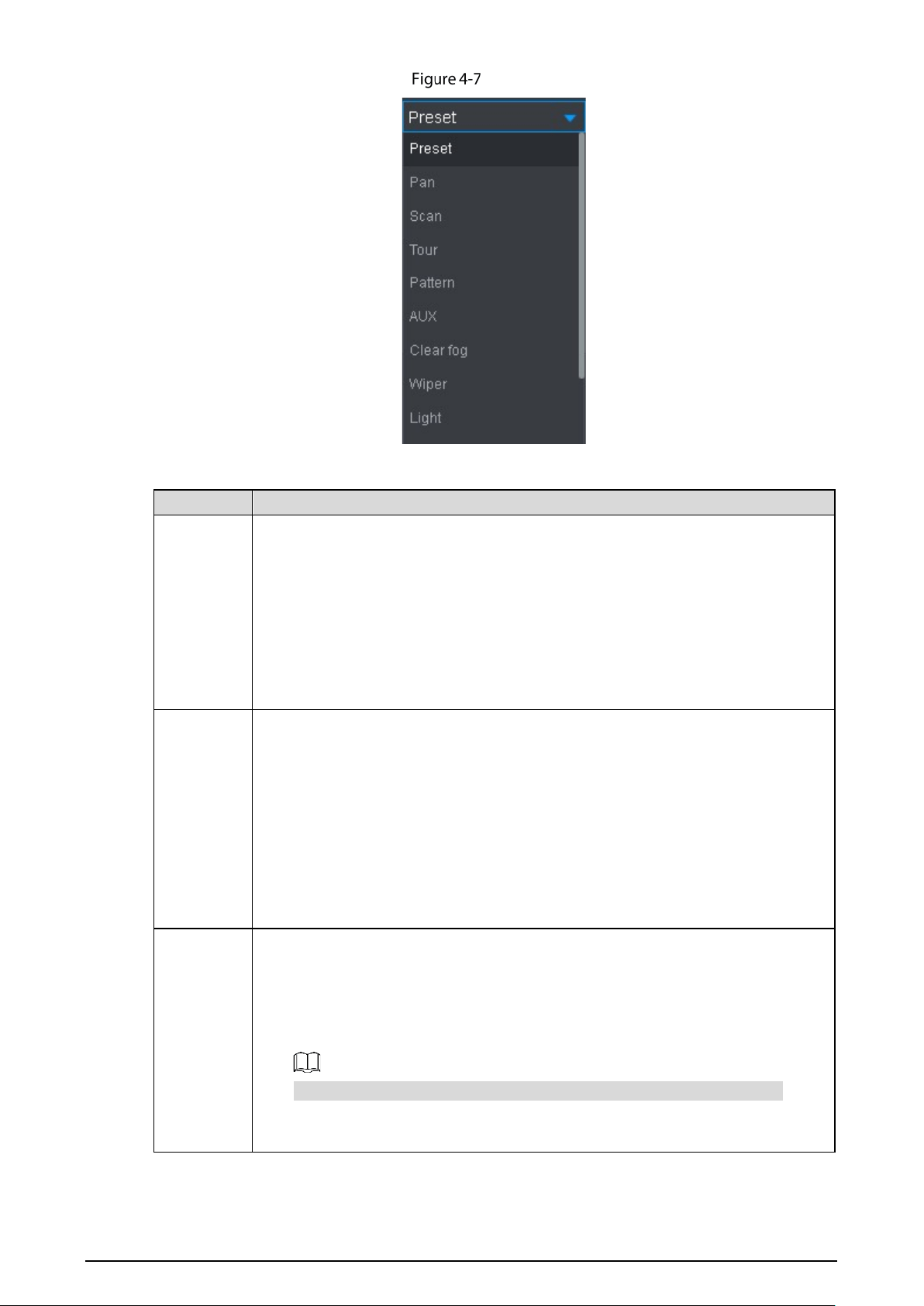
53
PTZ
Table 4-3 PTZ functions settings parameters
Parameter Description
Scan
After setting up scan, the camera automatically scans the configured left border
and right border.
1. In the PTZ Setup list, select Scan, and then click Setup.
Two buttons of Set the left border and Set the right border are displayed.
2. Through the PTZ control panel, move the camera to the left border that you
want and click Set the left border; move the camera to the right border that
you want and click Set the right border. Configuration finished.
3. Click Start to start scanning; click Stop if you want to end scanning.
Preset point
You can quickly move the PTZ camera to the configured presets after configuration.
In the PTZ setup list, select Preset, and then move the camera to the direction that
you want to monitor.
1. Click Preset, and control the PTZ console to turn the camera to the target
monitoring direction.
2. In the Preset box, enter the preset value.
3. Click Add to complete adding preset.
4. In the Preset box, enter the preset value, and then click Go to, the camera
moves to the location of preset. Click Del to delete the preset.
Calling
Tours
The PTZ camera repeats performing tours among the configured presets after
configuration.
1. Click To ur and set up the value of the tour
2. Click Add, and then enter the preset value
3. Click Add Preset or Del Preset to add or delete the presets
You can do this repeatedly to add presets to delete presets from the tour
4. Enter the tour value, and then click Start. The camera starts rotating according
to the configured tour. Click Del to delete the tour.

54
Touring
pattern
The PTZ camera repeats movement according to the configured patterns. The
operation records include the information such as the manual operations and focus
adjustment
1. Click Pattern and enter the pattern value
2. Click Add.
Two buttons of Start Rec and Stop Rec are displayed.
3. Click Start Rec. Then operate the PTZ control panel to adjust the camera with
regard to the parameters such as monitoring direction, zoom, and focus.
4. Click Stop Rec to complete the touring pattern setting.
5. Enter the pattern value, and then click Start. The camera moves according to
the configured patterns. Click Stop to stop the pattern.
Pan
In the PTZ Setup list, Click Pan, and then click Start. The camera keeps rotating
with 360° horizontally. Click Stop to stop rotating.
Light
Controls the light of external Recorder through RS-485 command. To use this
function, make sure it is supported on the external Recorder
In the PTZ Setup list, Click Light. Click On to turn on the light, and click Off to turn
off the light.
Using Flip
function
Select and click Flip if you want to flip display the video image
Reset
Click Reset to reset the PTZ
POFE
If you select this, PTZ will automatically turn to certain fixed position after device
on.
To make this function work, you need to configure preset 2 first, and then turn on
the device and enable POFE, PTZ will turn to preset 2 position.
PONE
If you select this, PTZ will automatically turn to certain fixed position after device
off.
This function needs to configure preset 65 beforehand, after choosing this and turn
off device, PTZ will turn to that preset position.
4.1.3.3 PTZ Menu
After the PTZ menu is turned on, it displays on the monitoring window. You can configure the
settings for the options such as camera, PTZ, and system, and apply the settings through arrow
buttons and Save button.
This function is supported only on the camera with PTZ menu function.
Turn on the camera monitoring screen.
On the PTZ control interface, click the PTZ Menu tab.
The PTZ Menu is displayed. See Figure 4-8. For details, see Table 4-4.
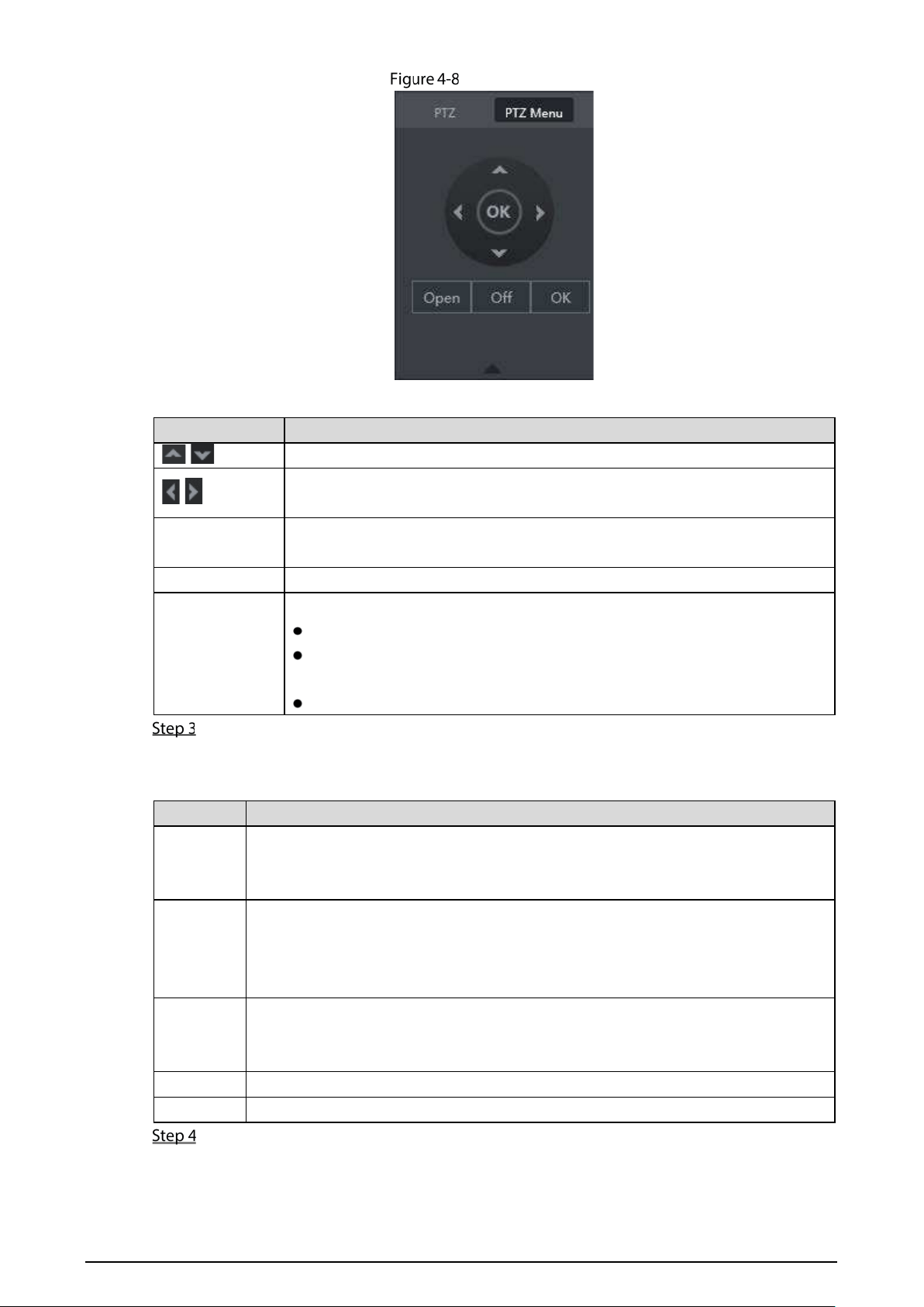
55
PTZ menu
Table 4-4 PTZ menu parameters description
Parameter Description
/
Up and down buttons: Select the item that is pointed.
/
Left and right buttons: When the item is pointed, perform configurations to the
item.
Open
Click Open to turn on the PTZ menu that is displayed on the monitoring
window.
Off
Click Off to turn off the PTZ menu.
OK
The OK button provides the following functions.
If there is sub-menu for an item, click OK to enter the sub-menu.
Move the pointer to Return, and then click OK to return to the higher
level menu.
Move the pointer to Exit, and then click OK to exit the menu.
Click On.
The OSD menu is displayed on the monitoring screen.
Table 4-5 OSD menu parameters description
Parameter Description
Camera
Move the pointer to Camera, and then click OK to enter the sub-menu of Camera.
You can configure the camera parameters such as image, exposure, backlight, white
balance, day & night, zoom, and focus.
PTZ
Move the pointer to PTZ Setup, and then click OK to enter the sub-menu of PTZ
Setup.
You can configure the PTZ parameters such as preset, tour, scan, pattern, pan, and
reboot.
System
Manager
Move the pointer to System, and then click OK to enter the sub-menu of System.
You can configure the settings such setting analog PTZ, restoring factory default,
and viewing camera version and PTZ version.
Back
Move the pointer to Return, and then click OK to return to the higher level menu.
Exit
Move the pointer to Exit, and then click OK to exit the menu.
Click Off to turn off the PTZ menu.
56
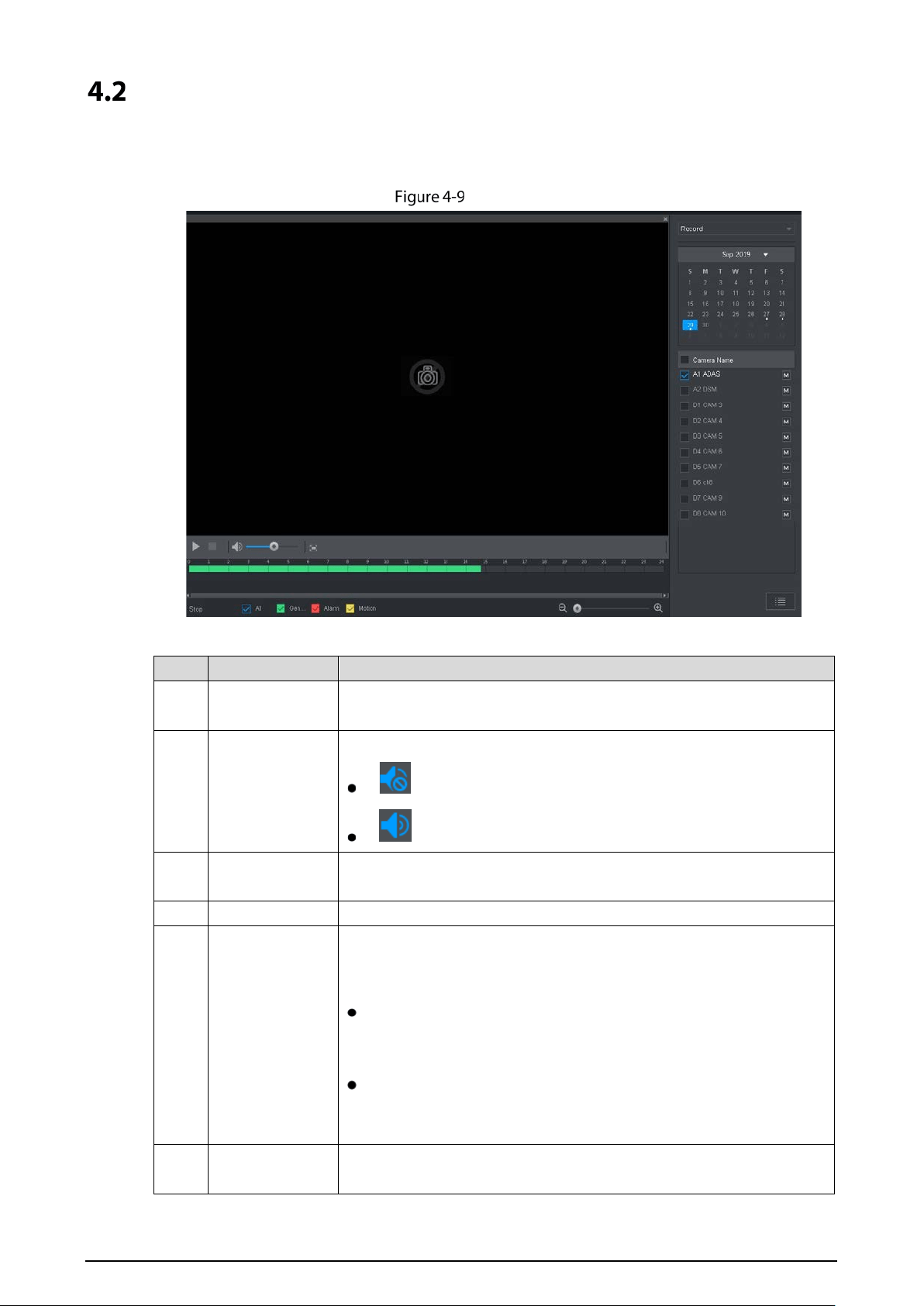
Record Playback
On the SEARCH interface, you can play back or download video recording files.
On the main web interface, click SAERCH.
Playback
Table 4-6 Playback function bar
No. Function Description
1
Playback control
bar
See "4.2.1 Playback Control Bar."
2
Volume
adjustment
Controls playback volume, including:
, means mute.
, means not mute, and the volume can be adjusted.
3
Full screen
button
To play the video recording in full screen.
4 Video editing Captures and saves certain video sections.
5 Sync
With Sync selected, when you click in the progress bar to play back the
recordings, the playback time of other channels will sync with the
selected channel in the following ways:
If the playback time of other channels is before the time of the
selected channel, other channels will speed up the playback
till synced with the selected channel.
If the playback time of other channels is after the time of the
selected channel, other channels will pause to wait till synced
with the selected channel.
6
Record type
selection
The record types include Regular, MD, and Alarm. You can select the
type as needed.
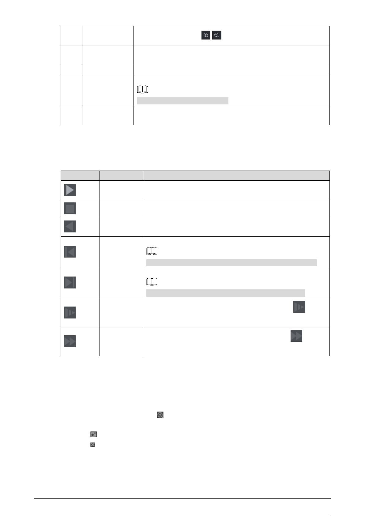
57
7 Time bar
Move the slider or click / to adjust the time bar.
8 Playback type
To select the playback type. Only record playback is supported at
present.
9 Date selection Click to select the date the recording on which you want to play back.
10 Camera name
You can set the cameras to focus on.
You can select up to 4 cameras.
11 File list
In the file list, you can play back the recordings by file name, download
video recordings by file name or time, and verify the completeness.
4.2.1 Playback Control Bar
Table 4-7 Playback control bar
Icon Function Description
Play
When this icon displays, it means the video is paused or not being
played. You can click this icon to play the video.
Stop Click this icon to stop playback.
Backward
playback
Click this icon to play the video recording backward.
Previous
frame
Click this icon to jump to the previous frame.
You need to pause the playback before using play by frame.
Next frame
Click this icon to play the next frame.
You need to pause the playback before using play by frame.
Slow
playback
Click this icon to adjust the slow playback speed. Click to
start slow playback.
Fast playback
Click this icon to adjust the fast playback speed. Click to start
fast playback.
4.2.2 Playing Back Video Recordings
You can play back video recordings by time or file name. During playback, you can conduct the
following operations.
In the channel window, click at the upper right corner and select the area you want to
enlarge. The area is enlarged. Click this icon again or right-click in the window to exit.
Click at the upper right corner to take a snapshot.
Click at the upper right corner to close playback.

58
4.2.2.1 Playing Video Recordings by Date
Select the date for searching for the video recordings, and set the corresponding channel as
needed.
Select a date with video recordings and the channel window, and then select the record
type.
Record type
Click to start playing back video recordings.
4.2.2.2 Playing Video Recordings by File Name
Select the date for searching for the video recordings, and set the corresponding channel as
needed.
Select a date with video recordings and the channel window.
Click File list.
The video recordings are displayed in the list.
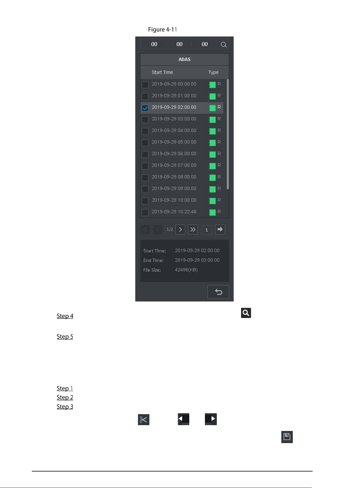
59
File list
Set the start time of the file to be searched for, and then click . The recording files are
displayed.
Double-click the video recordings to start playback.
4.2.3 Clipping Recording File
You can clip sections of video recordings and save to the PC.
Search for the video recordings that you want to clip by using the calendar and timeline.
Select the channel number.
Clip the video by either of the following ways.
Method A: Click , and the and sliders appear at the two ends of
the timeline. Move the sliders to the proper time points, and then click to clip
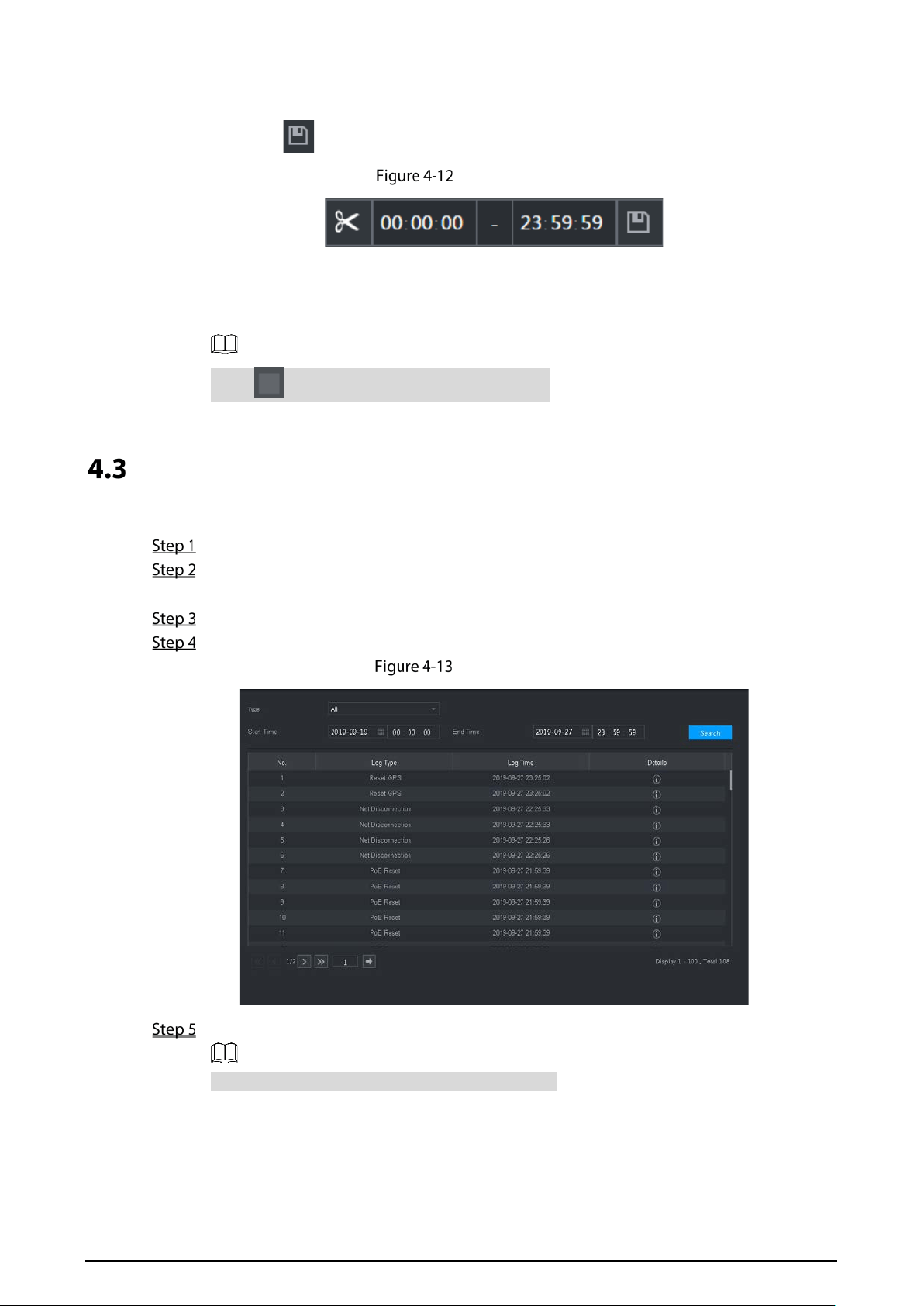
60
and save the section between the time points.
Method B: In the text box shown below, enter the start time and end time, and then
click to clip and save the section during this period.
Clip and save
The system displays a downloading progress bar. After the download is completed, the
clipped video files are saved in the "RecordDownload" folder by default. You can also change
the path as needed.
Click to stop downloading the recordings.
Viewing Alarm Info
You can view the alarm information during a fixed period.
On the main web interface, select ALARM > Alarm Info.
Select Type to set the alarm type to be searched for, including All, Motion Detect, Video Loss,
Tampering, Abnormality, Local and Smart Alarm.
Set the start time and end time.
Click Search. Alarm information in the set type during the set period is displayed.
Alarm info (2)
Click Backup to back up the obtained alarm information to a local directory.
You need to install relevant controls before backup.

61
5 System Settings
You can set up system information following instructions on the Local interface or web interface.
This section introduces the web interface instructions. The Local interface is similar and would
not be elaborated here.
Some functions can only be configured on the Local interface. The actual interface shall
prevail.
Some functions are not used in actual operations, so they are not described in detail in the
document.
In this section, when you have configured the settings for a channel, click Copy to apply
the settings to other channels. Click Refresh to display the latest configuration. Click
Default to restore to factory default settings.
Configuring Alarm Event Settings
Alarm information settings include the setting of video detection, alarm input, abnormality and
alarm output.
5.1.1 Configuring Video Detect Settings
Video detection includes motion detection, video loss, and tampering. This function detects the
abnormal changes and triggers alarms.
5.1.1.1 Configuring Motion Detect Settings
When the moving object appears and moves fast enough to achieve the preset sensitivity value, the
system triggers an alarm and alarm linkage.
On the main web interface, select ALARM > Video Detection > Motion Detect.
Select the channel number and select Enable to enable the motion detect function for the
channel.
Set MD region.
1) Click Setting behind Region.
The Setting interface is displayed.
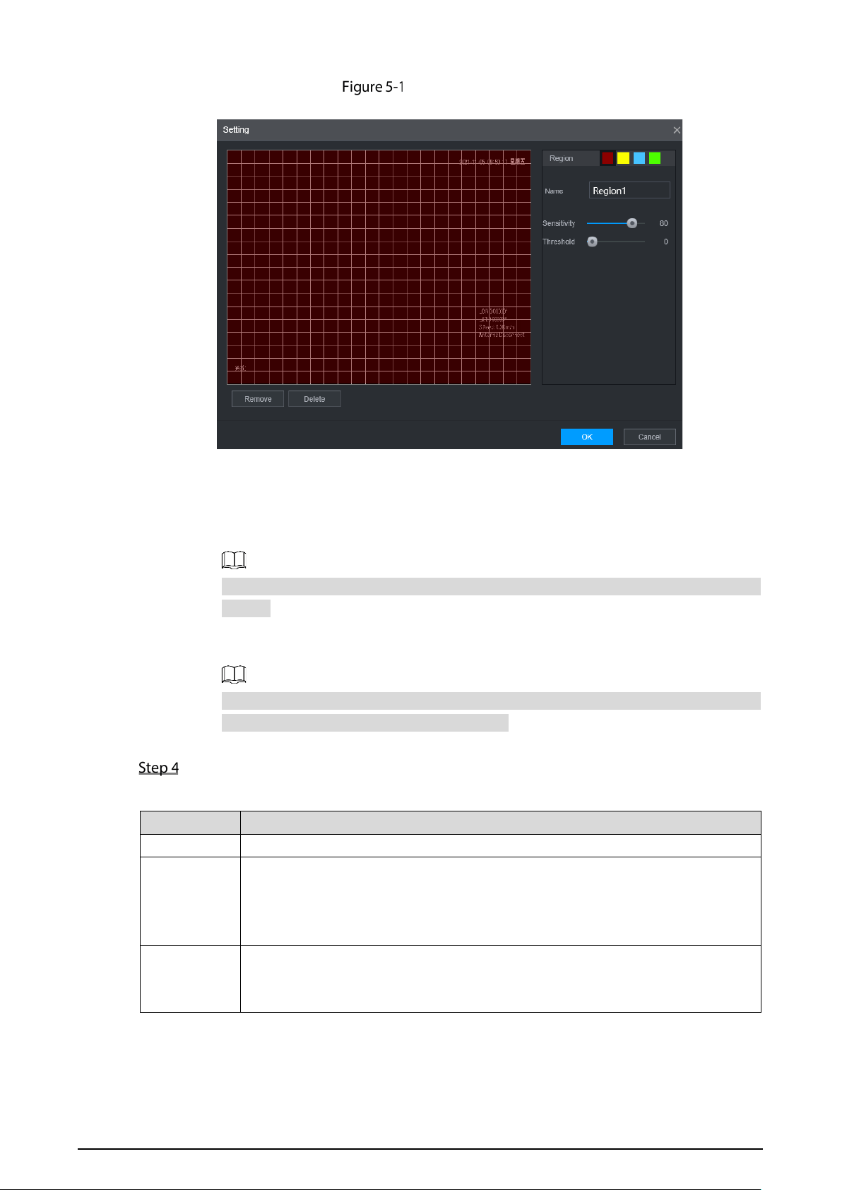
62
Region setting
2) Select a region and name it.
The higher the sensitivity value is, the easier the motion detect is triggered; the lower
the threshold is, the easier the motion detect is triggered. By default, the whole video
image is for motion detect.
Each color represents a separate region, and you can set different motion detect
regions.
3) Hold down the left button of the mouse, drag to select the region to be detected, and
set up its sensitivity and threshold value.
Channel alarm events: As long as any one of the four regions triggers alarm, the
channel that houses the region will give alarm.
4) Click OK.
Configure alarm linkage parameters.
Table 5-1 Alarm linkage parameters
Parameter Description
Delay When an alarm ends, the alarm recording will stop after a period of delay.
Alarm output
Connect with an alarm device (such as an alarm light or siren) on the alarm output
interface, click Setting to set the alarm output device, and activate the alarm
linkage output port. When an alarm event takes place, the system can trigger
corresponding alarm output devices.
Latch
Click Setting under Alarm Out to set the latch.
Set a length of time during which the device continues alarm output after the
alarm ends.
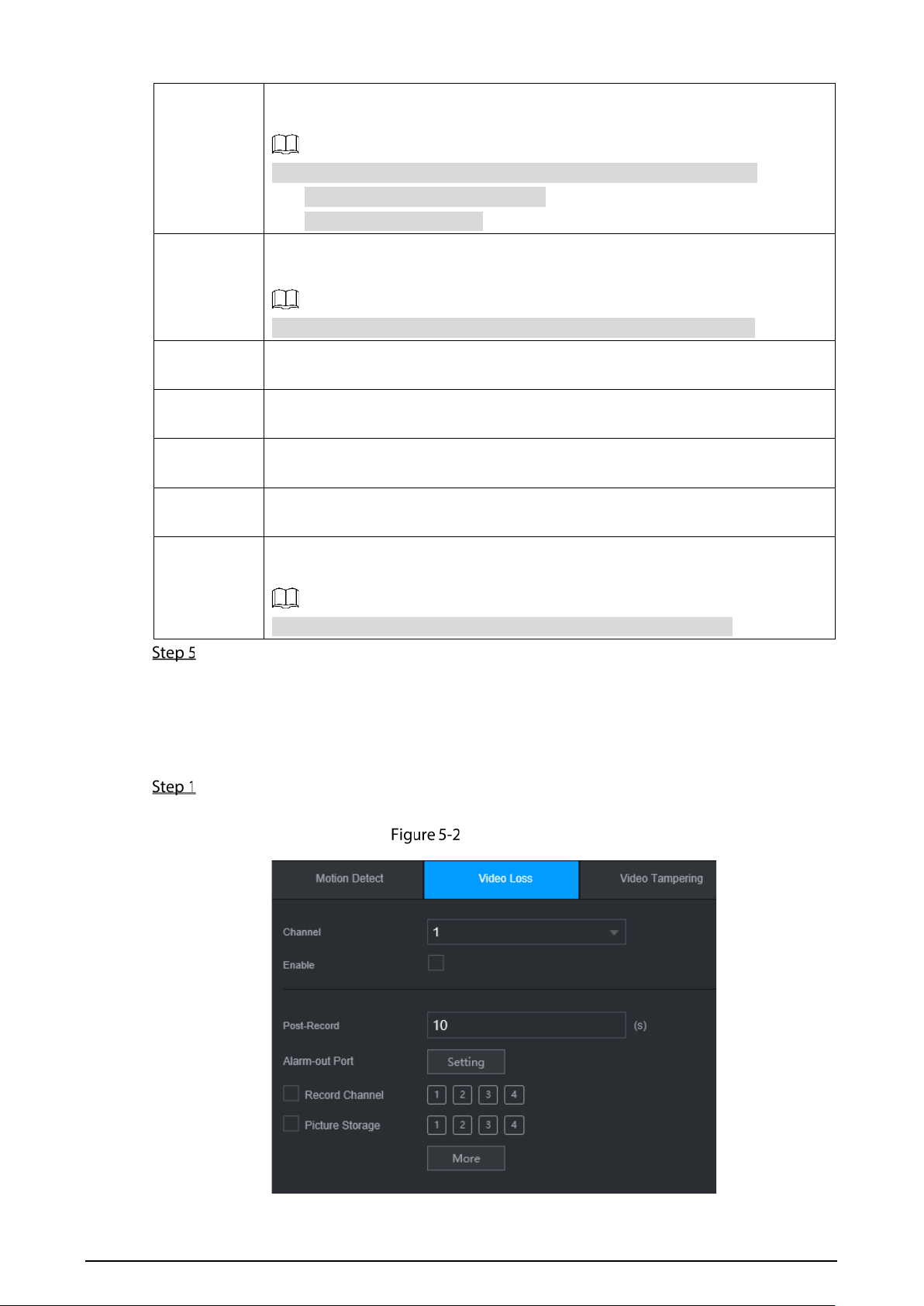
63
Record
channel
Select the corresponding check box and set a record channel. When an alarm
event occurs, the corresponding channel starts recording automatically.
Two more conditions must be satisfied before recording function works:
Motion detect recording is enabled.
Auto recording is enabled.
Snapshot
Select the corresponding check box and set the channel. When an alarm event
occurs, the corresponding channel starts capturing automatically.
You can also configure the frequency, size, and quality of the snapshots.
Anti-dither
Click More to set the anti-dither time.
The system records only one event during this period.
Show
message
Click More, and select the corresponding check box to trigger a pop-up message
in your local host PC when an alarm event occurs.
Buzzer
Click More, and select the corresponding check box to trigger a buzzer noise on
the device when an alarm event occurs.
Log
Click More, and select the corresponding check box to enable the device to create
a local alarm log when an alarm event occurs.
Send email
Click More, and select the corresponding check box. When an alarm event occurs,
the system sends email to the specified mailbox.
Set your e-mail first before enabling this function. See "5.6.3Cellular."
Click OK.
5.1.1.2 Configuring Loss Detect Settings
When video loss occurs, the system triggers an alarm and configured actions.
On the main web interface, select ALARM > Video Detection > Video Loss.
The Video Loss interface is displayed.
Video loss
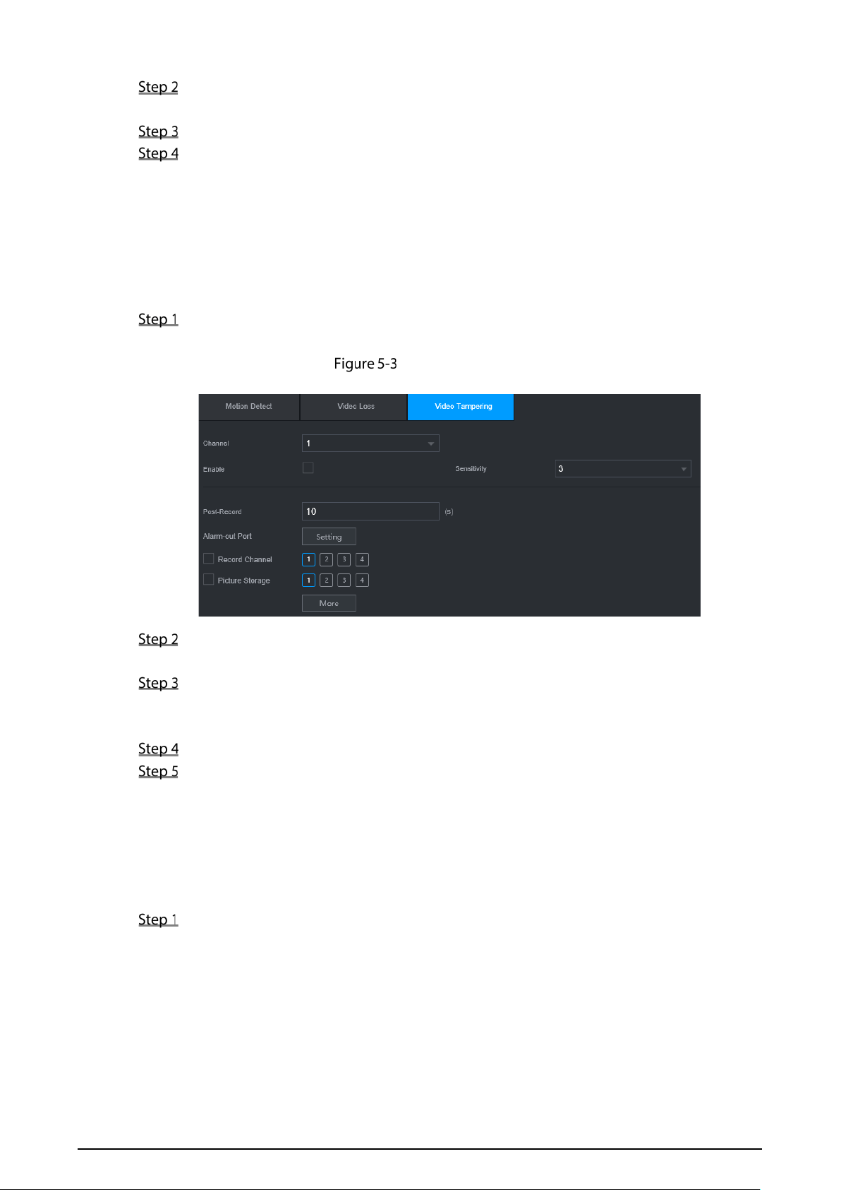
64
Select Channel and select Enable to enable the video tampering detect function for the
channel.
Configure alarm linkage parameters.
Click OK.
5.1.1.3 Configuring Tampering Settings
When the camera is covered intentionally, or the video is displayed in a single color due to sunlight
or other reasons, that is the monitoring cannot be continued normally, the system triggers alarm and
links to the configured actions.
On the main web interface, select ALARM > Video Detection > Video Tampering.
The Video Tampering interface is displayed.
Video Tampering
Select Channel and select Enable to enable the video tampering detect function for the
channel.
Set the sensitivity of detection.
The higher the sensitivity, the easier it is to detect a moving object, but the false alarm rate
might increase.
Configure alarm linkage parameters.
Click OK.
5.1.2 Configuring Alarm Input Settings
You can select different types of input according to different sources of alarm and set up alarm
output methods.
On the main web interface, select ALARM > ALARM > Local.
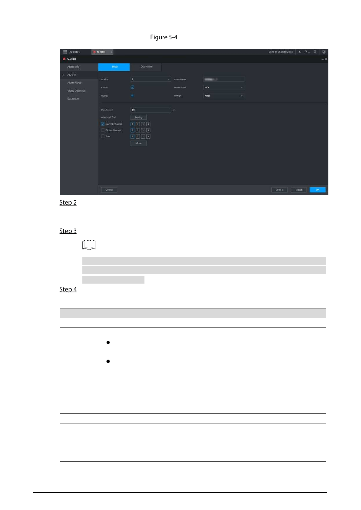
65
Alarm input
Click Local or Camera Offline tab as needed.
Local: The alarm signal detected by the alarm input port on the device.
Camera Offline: The alarm signal generated when the IP camera is offline.
Select the Alarm In channel number and select Enable.
For emergency alarm button, you can only select Channel 10 from the Alarm In drop-down
list. When you press the emergency alarm button, the Recorder will receive the emergency
alarm from Channel 10.
Configure more settings.
Table 5-2 Alarm input parameters
Parameter Description
Alarm name Enter a customized alarm name.
Type
If the Event Type is Local Alarm, configure this parameter.
NO: The alarm signal is disconnected normally. The alarm is triggered when
alarm signal is connected.
NC: The alarm signal is connected normally. The alarm is canceled when
alarm signal is disconnected.
Overlay
Select the Overlay check box to overlay alarm names onto channel images.
Trigger
If the Event Type is Local Alarm, configure this parameter.
If the alarm signal is 12V/24V voltage, select High as the triggering mode; if the
alarm signal is ground voltage, select Low as the triggering mode.
Post record When an alarm ends, the alarm recording will stop after a period of delay.
Alarm out
Connect the alarm device such as light and siren to the alarm output port. Select
the corresponding check box and set an alarm output device. With the alarm
linkage output port enabled, when an alarm event occurs, the system links the
alarm device to trigger an alarm.
66
Latch
Click Setting under Alarm Out to set the latch.
Set a length of time during which the device continues alarm output after the
alarm ends.
Record
channel
Select the corresponding check box and set a record channel. When an alarm
event occurs, the corresponding channel starts recording automatically.
Two more conditions must be satisfied before recording function works:
Alarm recording is enabled.
Auto recording is enabled.
Snapshot
Select the corresponding check box and set the channel. When an alarm event
occurs, the corresponding channel starts capturing automatically.
You can also configure the frequency, size, and quality of the snapshots.
Tour
Select the corresponding check box and the channel. When an alarm event
occurs, a tour of the selected channels is displayed on the device local interface.
When the alarm linkage tour is finished, the Live interface returns to the window
split mode as before the alarm occurs.
Anti-dither
Click More to set the anti-dither time.
The system records only one alarm input event during this period.
Show
message
Click More, and select the corresponding check box to trigger a pop-up message
in your local host PC when an alarm event occurs.
Buzzer
Click More, and select the corresponding check box to trigger a buzzer noise on
the device when an alarm event occurs.
Log
Click More, and select the corresponding check box to enable the device to create
a local alarm log when an alarm event occurs.
Send email
Click More, and select the corresponding check box. When an alarm event occurs,
the system sends email to the specified mailbox.
Set your e-mail first before enabling this function.
Click OK.
5.1.3 Configuring Exception
You can configure the ways to handle the device when errors occur.
On the main web interface, select ALARM > Exception > Disk.
The Disk interface is displayed. See Figure 5-5
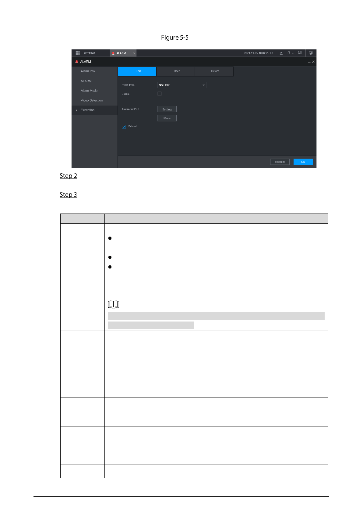
67
Disk
Select the event type, and select Enable to enable the handling of corresponding abnormal
events.
Configure more settings. See Table 5-3.
Table 5-3 Abnormality setting parameters
Parameter Description
Event type
You can configure corresponding abnormal events on the following three tabs.
HDD: To set the ways to handle abnormal HDD events, including No HDD,
HDD Errors, HDD No Space.
User: Set the ways to handle illegal login events.
Device: Set the ways to handle abnormal device events, including
Temperature Too H
igh, Low Battery Safety Exception, Network Security
Exception, Over Speed, Low Speed, Collision, Turnover, Rapid Turn, Rapid
Speedup, Sharp Brake and ACC Power Off.
The event type might be different depending on the model you purchased, and
the actual interface shall prevail.
Lower Than
Select Disk tab, and if the Event Type is Low Space, configure this parameter.
You can set the percentage of Disk remaining space. When Disk remaining space
is lower than this percentage, an alarm will occur.
Login
Attempt
Select User tab, and if the Event Type is Illegal Login, configure this parameter.
The maximum number of allowed password input errors during user login. If the
number of password input errors reaches this value, the user account will be
locked.
Lock time
Select User tab, and if the Event Type is Illegal Login, configure this parameter.
Set the time for locking the user account when the number of password input
errors reaches the set value.
High
Temperature
Select Device tab, and if the Event Type is High Temperature, configure this
parameter.
Enter the upper limit of device temperature. The alarm is triggered when the
device temperature exceeds this value.
Lower Than
Select Device tab, and if Event Type is Battery Low Voltage, configure this

68
Auto
parameter.
The supply voltage to the device from the vehicle and the percentage of available
supply voltage capacity. When the vehicle is in ACC Off, and the voltage supplied
to the device is less than the percentage of available capacity, the system triggers
an alarm.
Accumulator
voltage
Max speed
Select Device tab, and if the Event Type is Over Speed, configure this parameter.
The upper limit of vehicle speed. When the vehicle speed exceeds this value, the
system triggers an alarm.
Min speed
Select Device tab, and if Event Type is Low Speed, configure this parameter.
The lower limit of vehicle speed. When the vehicle speed is lower than this value,
the system triggers an alarm.
Alarm output
Connect the alarm device such as light and siren to the alarm output port. Select
the corresponding check box and set an alarm output device. With the alarm
linkage output port enabled, when an alarm event occurs, the system links the
alarm device to trigger an alarm.
Latch
Click Setting under Alarm Out to set the latch.
Set a length of time during which the device continues alarm output after the
alarm ends.
Show
message
Click More, and select the corresponding check box to trigger a pop-up message
in your local host PC when an alarm event occurs.
Send email
Click More, and select the corresponding check box. When an alarm event occurs,
the system sends email to the specified mailbox.
Set your e-mail first before enabling this function.
Buzzer
Click More, and select the corresponding check box to trigger a buzzer noise on
the device when an alarm event occurs.
System log
Click More, and select the corresponding check box to enable the device to
create a local alarm log when an alarm event occurs.
Refresh
Select the Refresh check box. If No Disk alarm occurs, the system restarts within
three minutes.
Click OK.
5.1.4 Configuring Alarm Out Settings
You can set the alarm output type.
On the main web interface, select ALARM > Alarm Mode.
The Alarm Mode interface is displayed.
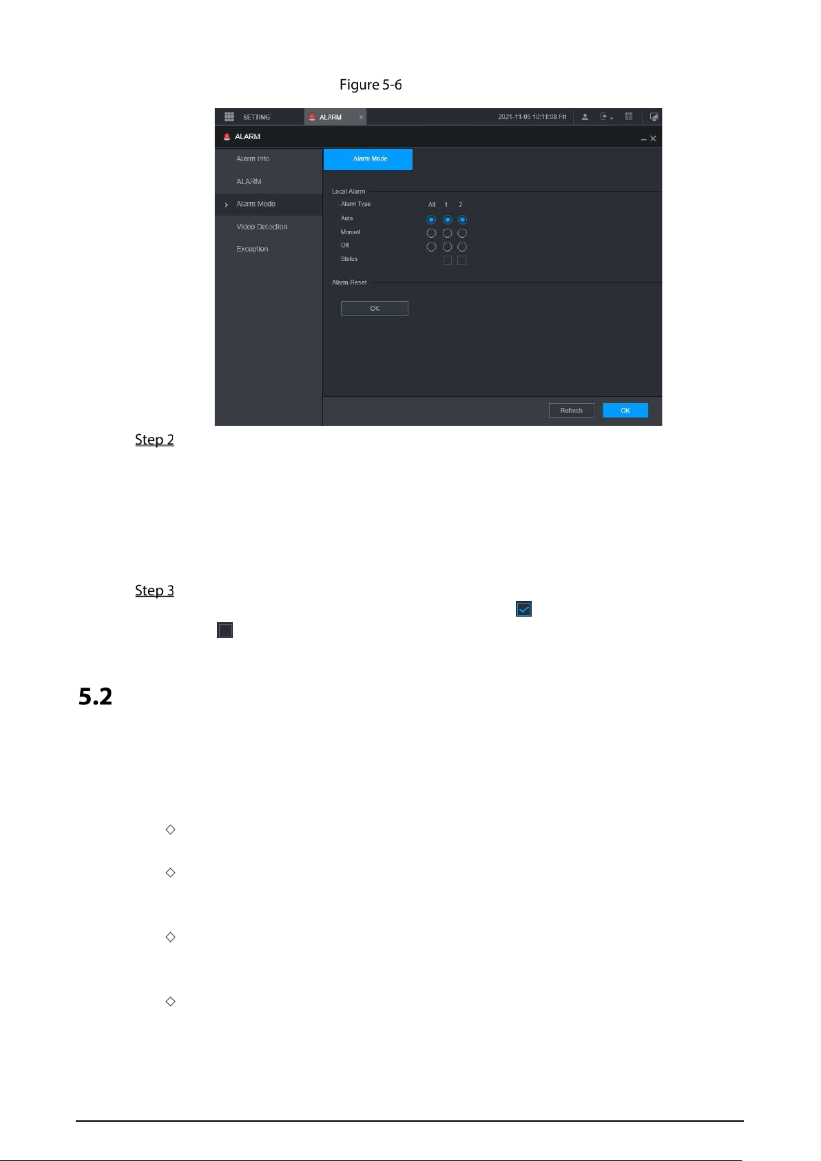
69
Alarm mode
Select alarm type.
Auto: After the alarm linkage is configured, when an alarm event occurs, the corresponding
alarm output port triggers an alarm.
Manual: After the alarm linkage is configured, no matter whether there is an alarm event
occurs, the corresponding alarm output port triggers an alarm.
Stop: After the alarm linkage is configured, no matter whether there is an alarm event occurs,
the corresponding alarm output port never triggers an alarm.
Click OK.
Status: Indicates the status of each alarm output port. indicates there is an alarm output,
and indicates there is not.
Configuring AI Settings
AI features include: Face detection and recognition, active and safe drive, license plate
detection, and passenger flow counting. Only when the AI feature is enabled and set can the
corresponding function take effect.
Face Detection and Recognition
Face detection: The system can analyze and process the video images collected by cameras.
When specific face information is detected, the system triggers alarm linkage.
Face matching: The system can compare the detected faces with the information in the
configured face library, and trigger alarm linkage.
Active and safe drive
ADAS: Advanced Driver Assistance System for detecting Lane Departure, Vehicles Too Close
and Vehicle Collision pre-warnings, and alarm linkage is triggered and reported to the
platform.
DSM: The system can analyze and process the driver behavior information collected by
cameras, and detect actions such as lowering head, yawning, smoking, looking around, and
not in position.
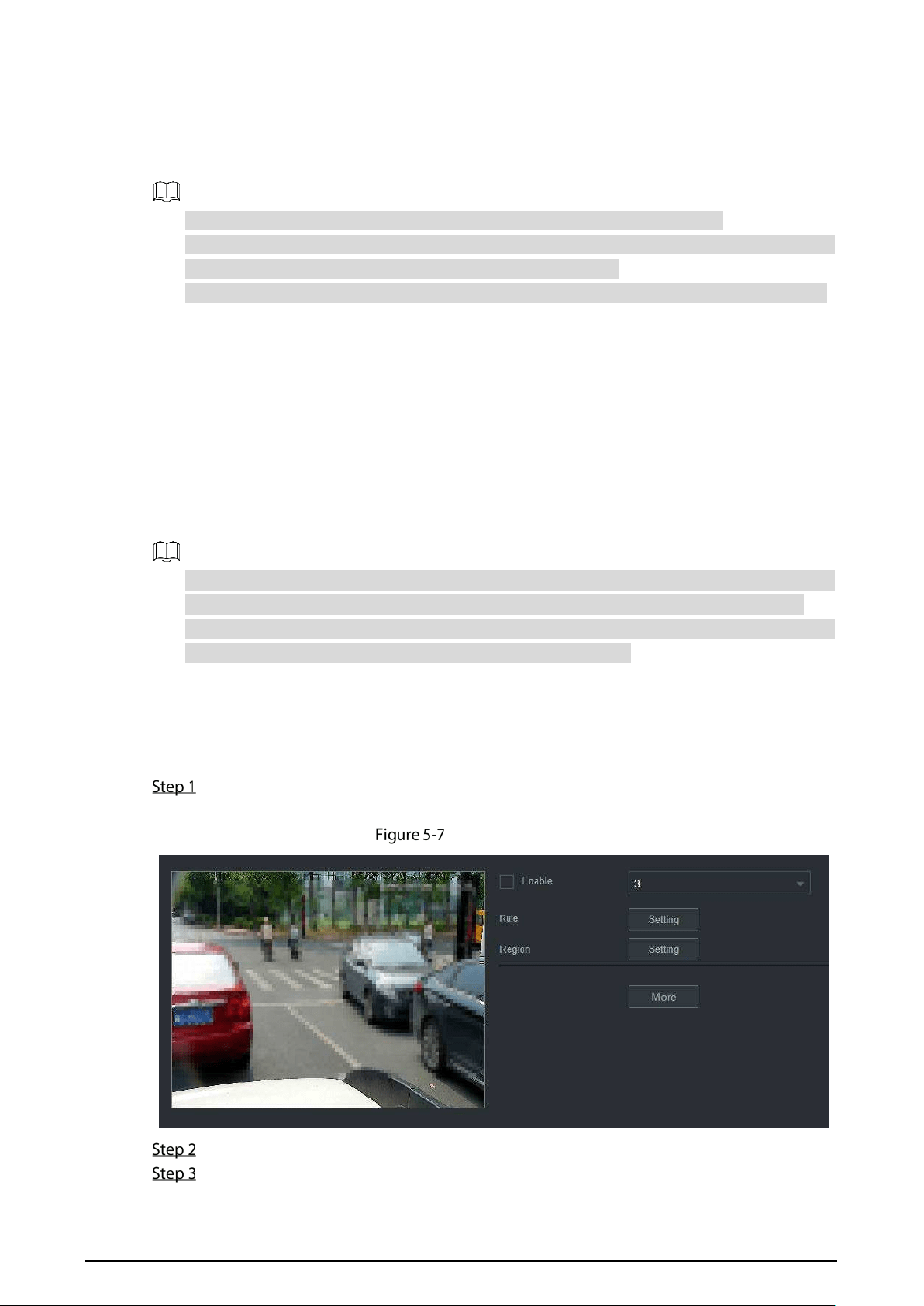
70
License plate detection: Collect license plate and compare the key information with the preset
detection rule and trigger an alarm once the detected behavior matches the detection rule.
Passenger flow counting: Select the alarm channel and count the passenger flow data of
the station.
Before enabling the face matching function, enable the face detection function.
You can enable up to 4 smart functions at the same time. (1-channel DSM, 1-channel ADAS,
1-channel face detection and 1-channel license plate detection).
You can enable up to 2 channels of face detection and license plate detection at the same time.
5.2.1 Face Detection and Recognition
5.2.1.1 Face Detection
The system can analyze and process the video images collected by cameras, and detect whether
there are faces in the video images. You can find the videos with detected faces through AI search
and play back these videos.
The installation position of the camera should be horizontal with the face as much as possible,
and the overhead angle should not exceed 15 °, and the backlight scene should be avoided.
Due to the update of the device version, the description may be inconsistent with the interface.
Please refer to the actual display interface of the device for details.
5.2.1.1.1 Parameter Settings
You can set up face detection parameters. When specific face information is detected, the
system will trigger alarm linkage.
On the main web interface, select AI > Parameters > Face Detection.
The Face Detection interface is displayed. See Figure 5-7.
Face detection
Select the channel number and select Enable to enable face detection.
Configure parameters. See Table 5-4 for details.
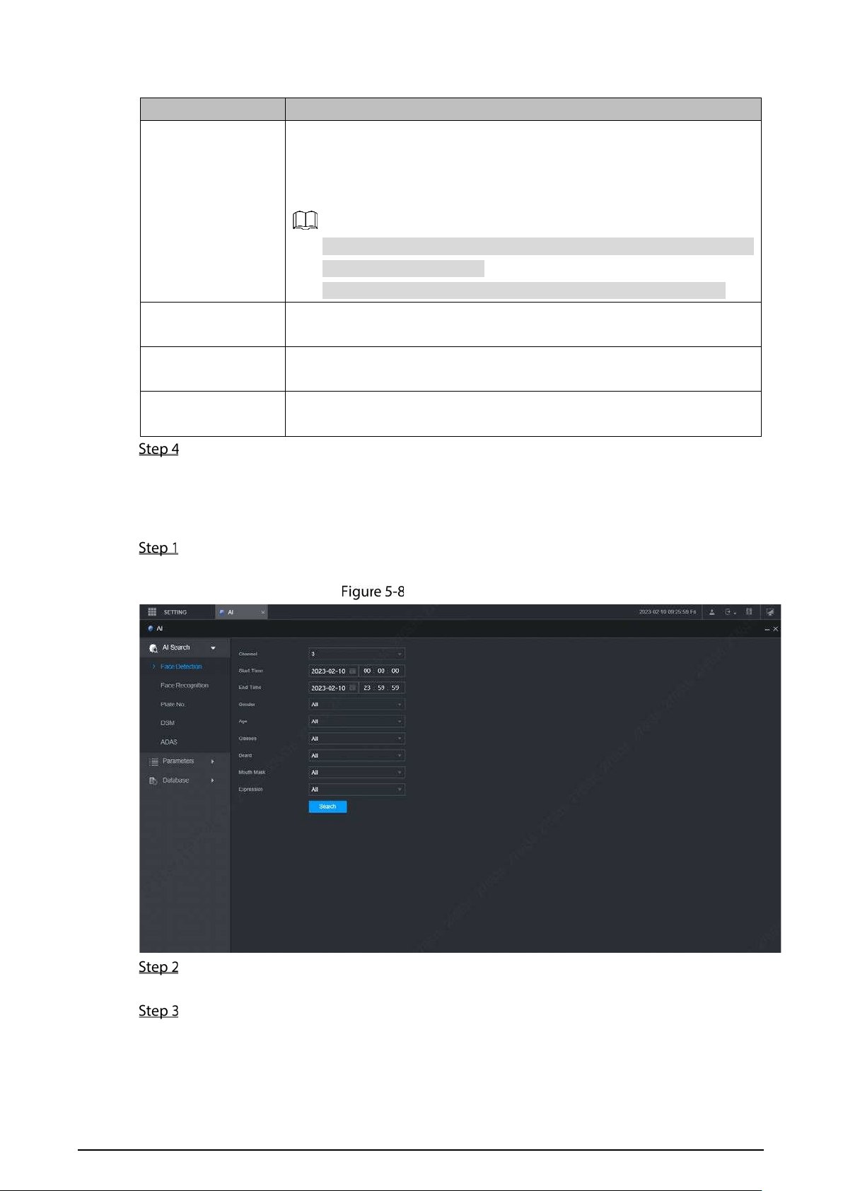
71
Table 5-4 Face detection parameters
Parameter Description
Rule
1. Click Setting.
2. Set the maximum size and minimum size of the face detection region.
Press and hold the left mouse button and drag four corners of the
blue box to adjust the size.
Faces smaller than the minimum size or bigger than the maximum
size will not be detected.
The maximum size cannot be smaller than the minimum size.
Region
Click More Setting and select Region.
Set up the face detection region.
Buzzer
Click More Setting and select Buzzer.
Activate a buzzing sound when an alarm is triggered.
System log
Click More Setting and select System Log.
Record face detection log information in the system log.
Click OK.
5.2.1.1.2 AI Search
You can set up search parameters and filter out specific face recordings for playback.
On the main web interface, select AI > AI Search > Face Detection.
The Face Detection interface is displayed.
Face Detection
Select the channel, start time and end time, and select face detection details (such as gender,
age, glasses, beard, mask and face) as needed.
Click Search.
The search results are displayed. See Figure 5-9.
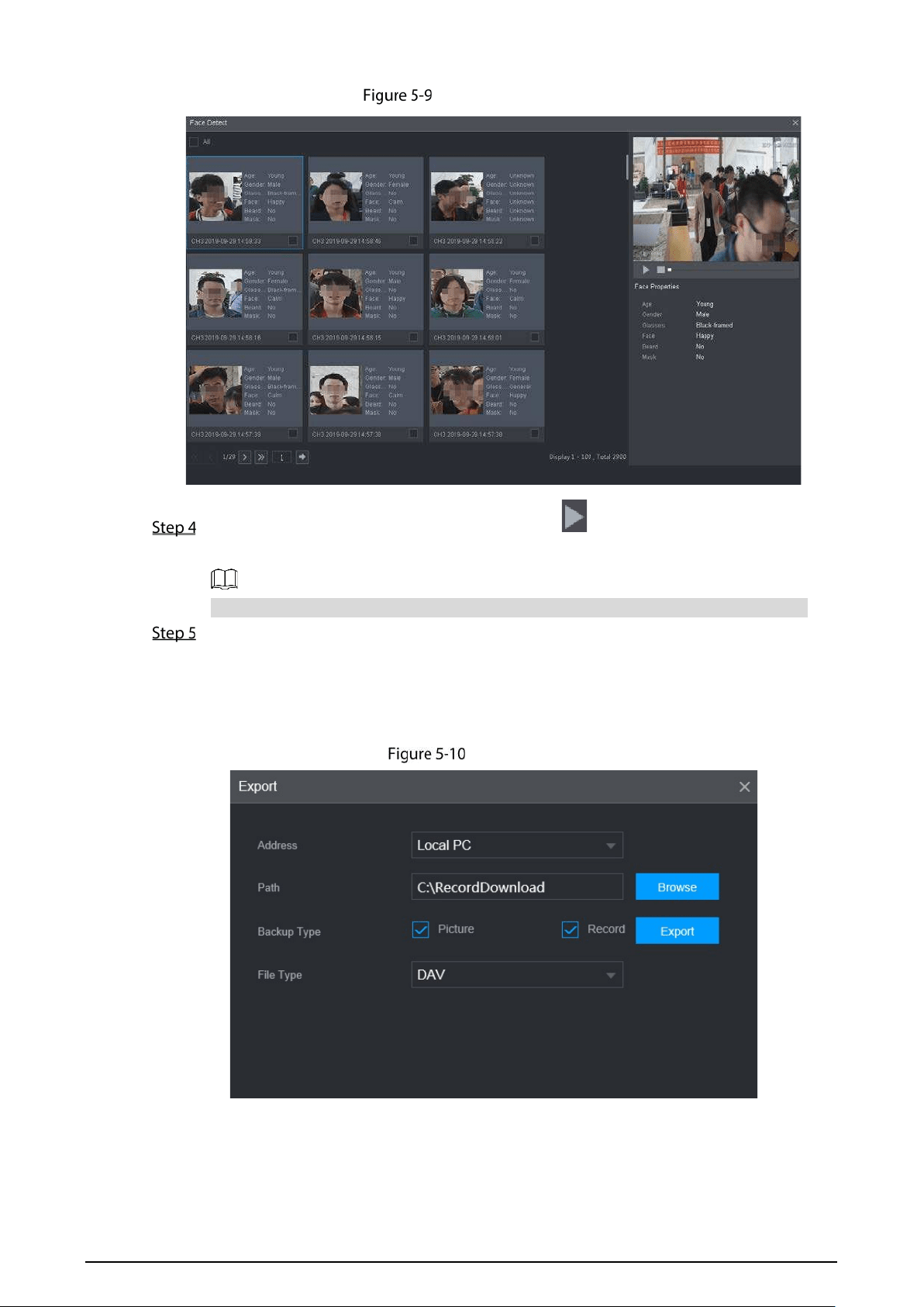
72
AI search result (1)
Select the face image you need to view, and click . The system starts playing back the
video file that the image belongs to.
Double-click the playback interface to switch between full screen and small screen.
(Optional) Back up files.
1) Select files and click Backup.
The Export interface is displayed. See Figure 5-10.
2) Select the backup address, path, backup type and file type, and click Export.
File backup is completed.
Export (1)
5.2.1.2 Face Matching
The face matching function can be used in two scenarios: AI Live and AI Search.
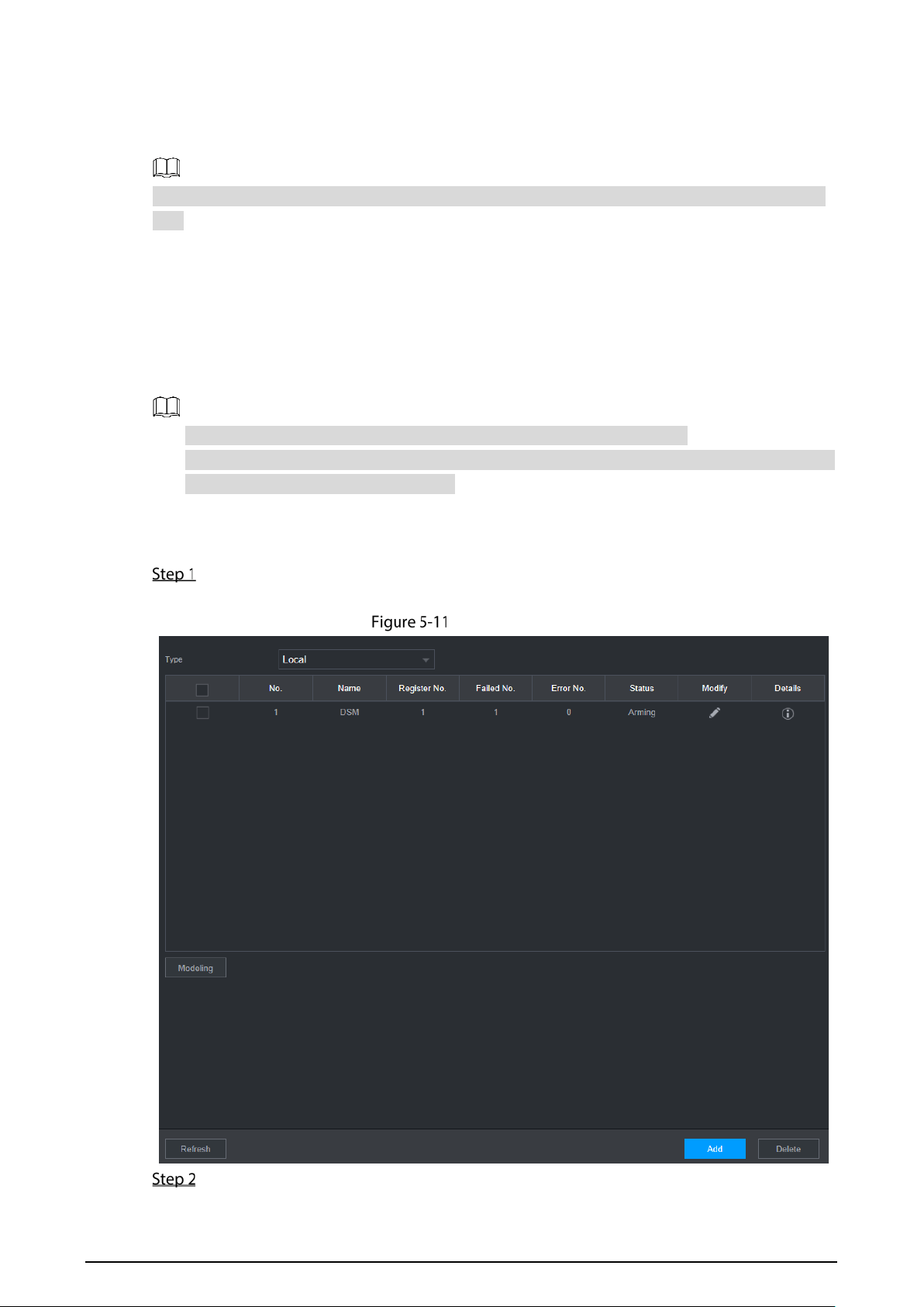
73
In AI Live, the system can compare the detected faces with the faces in the configured face
library, and display the results in AI Live interface.
In AI Search, the system can search by face attributes or image comparison.
Before enabling the face matching function, enable the face detection function for the channel
first.
5.2.1.2.1 Face Library Management
After successfully configuring the face library, the detected faces are compared with the
information in the face library. Configuring a face library includes creating a face library, adding
face images, and modeling faces.
You can create up to 20 face libraries and register up to 100,000 face images.
To protect privacy, the faces in the images have been blurred intentionally.
There is a DSM face library by default. It is configured from the platform, and cannot be
modified and removed on the Recorder.
Creating Face Library
On the main web interface, select AI > Database> FACE LIBRARY.
The FACE LIBRARY interface is displayed. See Figure 5-11.
Face library (1)
Click Add.
The Add interface is displayed. See Figure 5-12.
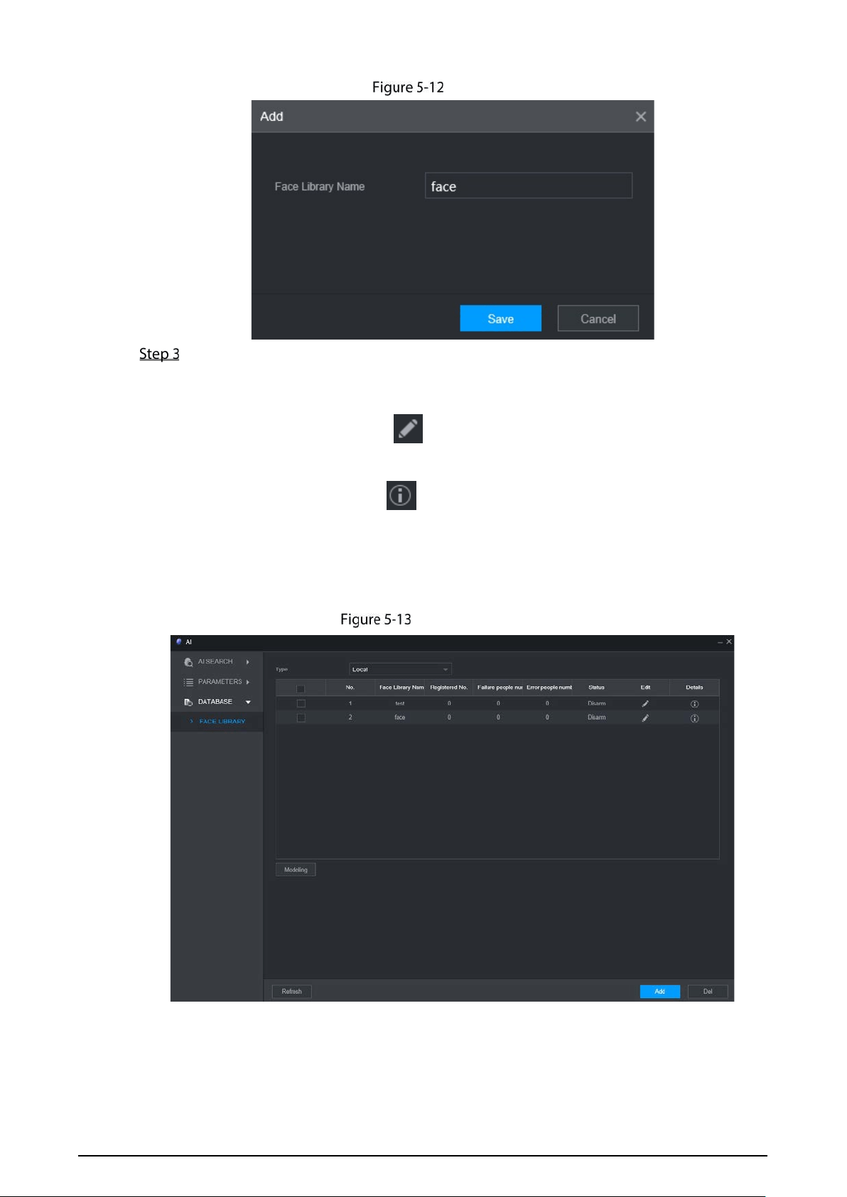
74
Add
Enter Face Library Name and click OK.
The face library is saved successfully, and the FACE LIBRARY (2) interface is displayed. See
Figure 5-13.
Click the corresponding in the face library list to modify the face library
name.
Click the corresponding in the face library list to add face images to the face
library.
Select a face library and click Modeling. The system will extract the feature
attributes of images in the face library for subsequent face matching.
Select a face library and click Del to delete it.
Face library (2)
Adding Face Images
You can add face images to the created face library, and single add and batch import are both
supported.
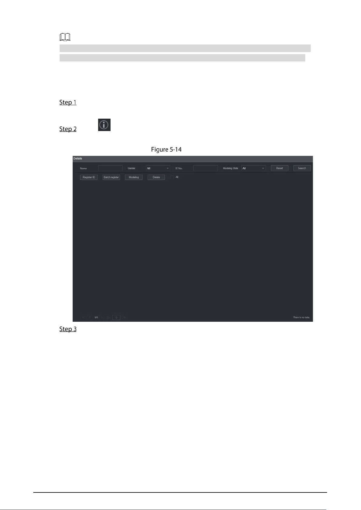
75
Both single add and batch import require to obtain face images from the USB flash drive.
Images should be smaller than 256K with resolution from 200×200 through 6000×5000.
Single Add
You can add face images one by one. When registering a small number of face images, use
this method.
On the main web interface, select AI > Database> FACE LIBRARY.
The FACE LIBRARY interface is displayed. See Figure 5-13.
Click corresponding to the face library to be configured.
The Details interface is displayed. See Figure 5-14.
Details (1)
Click Register ID.
The Register ID interface is displayed. See Figure 5-15.
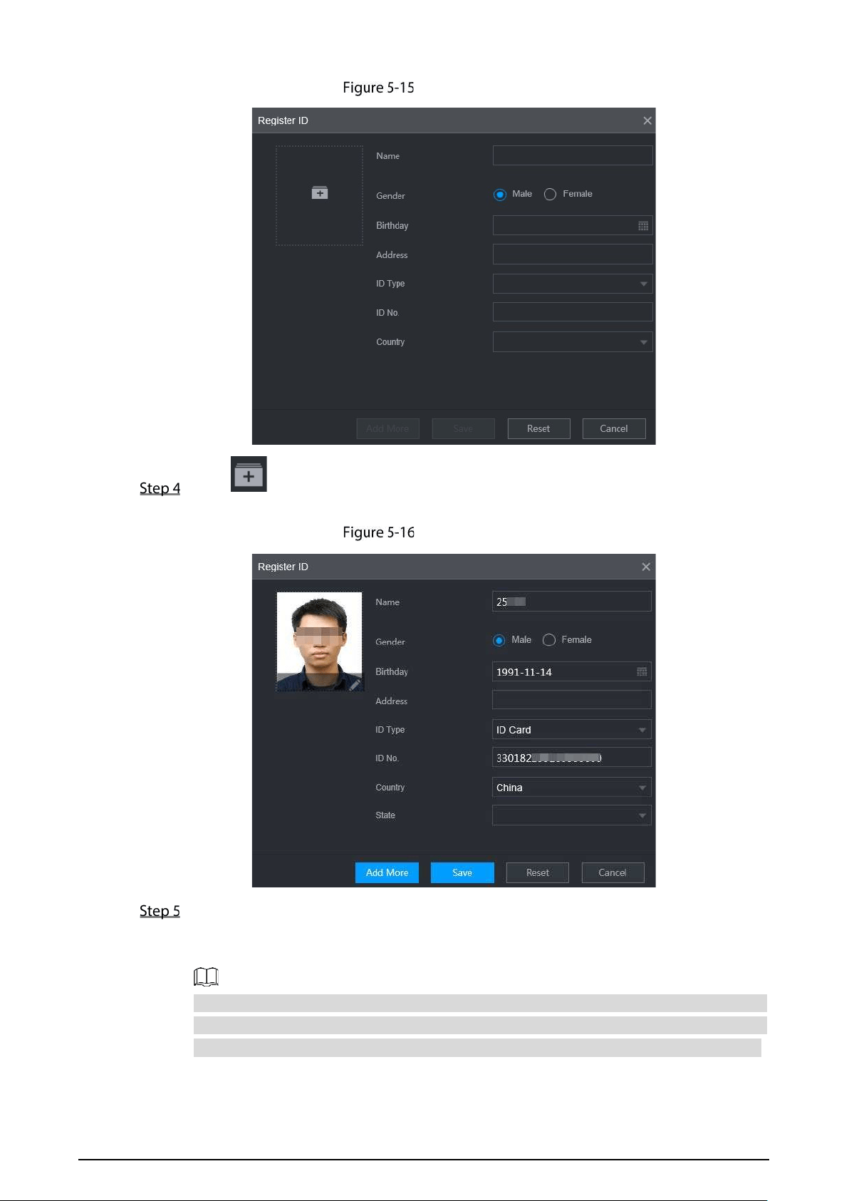
76
Register ID (1)
Click to add face photos.
Select a picture and fill in registration information. For system display, see Figure 5-16.
Register ID (2)
Click OK.
The system displays "Operation is done successfully" and returns to the Details interface.
See Figure 5-17.
If face image shows "Modeling", it means that the system is extracting the feature
attributes of the photo. Click Search to refresh the interface, and "Modeling
succeeded" is displayed. If modeling fails, the photo cannot be used for face matching.
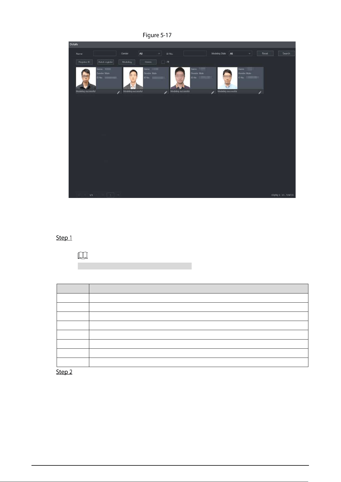
77
Details (2)
Batch Add
If there are many face images to be registered, you can use the batch add function to import
face images in batch.
Name the face images in the format of "Name#S Gender#B Birthday#N Country#P
Province#T IDType#MID No.#A Address.jpg." For details, see Table 5-5.
Name is required and the rest are optional.
Table 5-5 Naming rules for batch import
Item
Description
Name Enter the corresponding name.
Gender Enter number 1 for male and 2 for female.
Birthday Fill in the number in the format of yyyy-mm-dd, for example, 2017-11-23.
Country Enter the corresponding country abbreviation.
Province Fill in the English name of the province.
ID Type Fill in the numbers, "1" for ID card, "2" for passport, and "3" for official card.
ID No. Fill in the ID number.
Address Enter the corresponding residence address.
On the face library details interface, click Batch register.
The Batch register interface is displayed. See Figure 5-18.
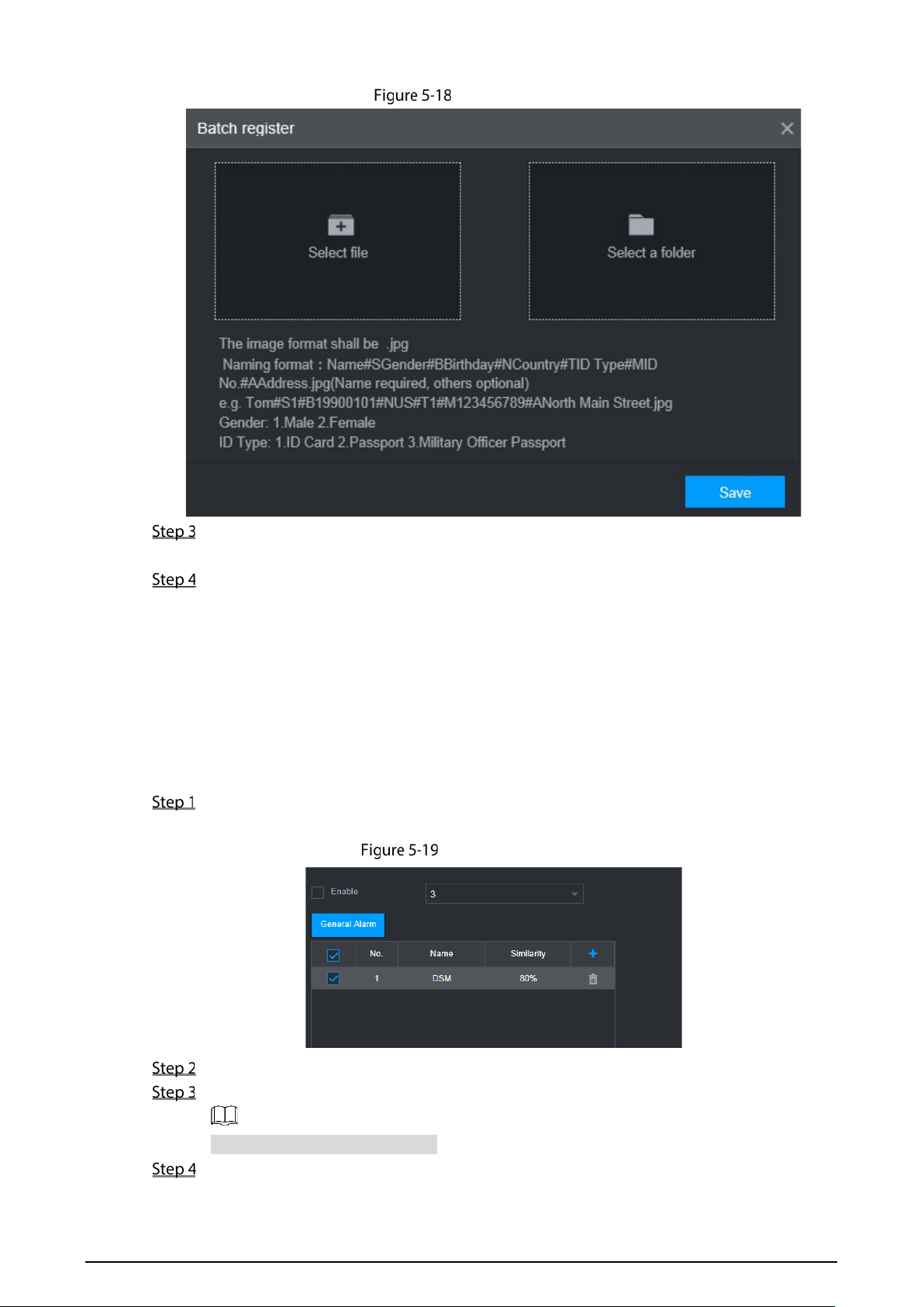
78
Batch register
Click Select file (up to 500 images at a time) or Select a folder to select a file path to import
the images.
Click OK.
5.2.1.2.2 Configuring Face Matching Settings
The system compares the detected faces with the faces in the face library to see whether the
detected faces are in the face library. The comparison results are directly displayed in the AI
Live interface and AI Search interface, and the system triggers alarm linkage.
Procedure
On the main web interface, select AI > Parameters > Face Matching.
The Face Matching interface is displayed. See 错误!未找到引用源。.
Face Matching (1)
Select the channel number. Select Enable to enable the face matching function.
Select the type.
Only AI by Device is supported.
Set face library.
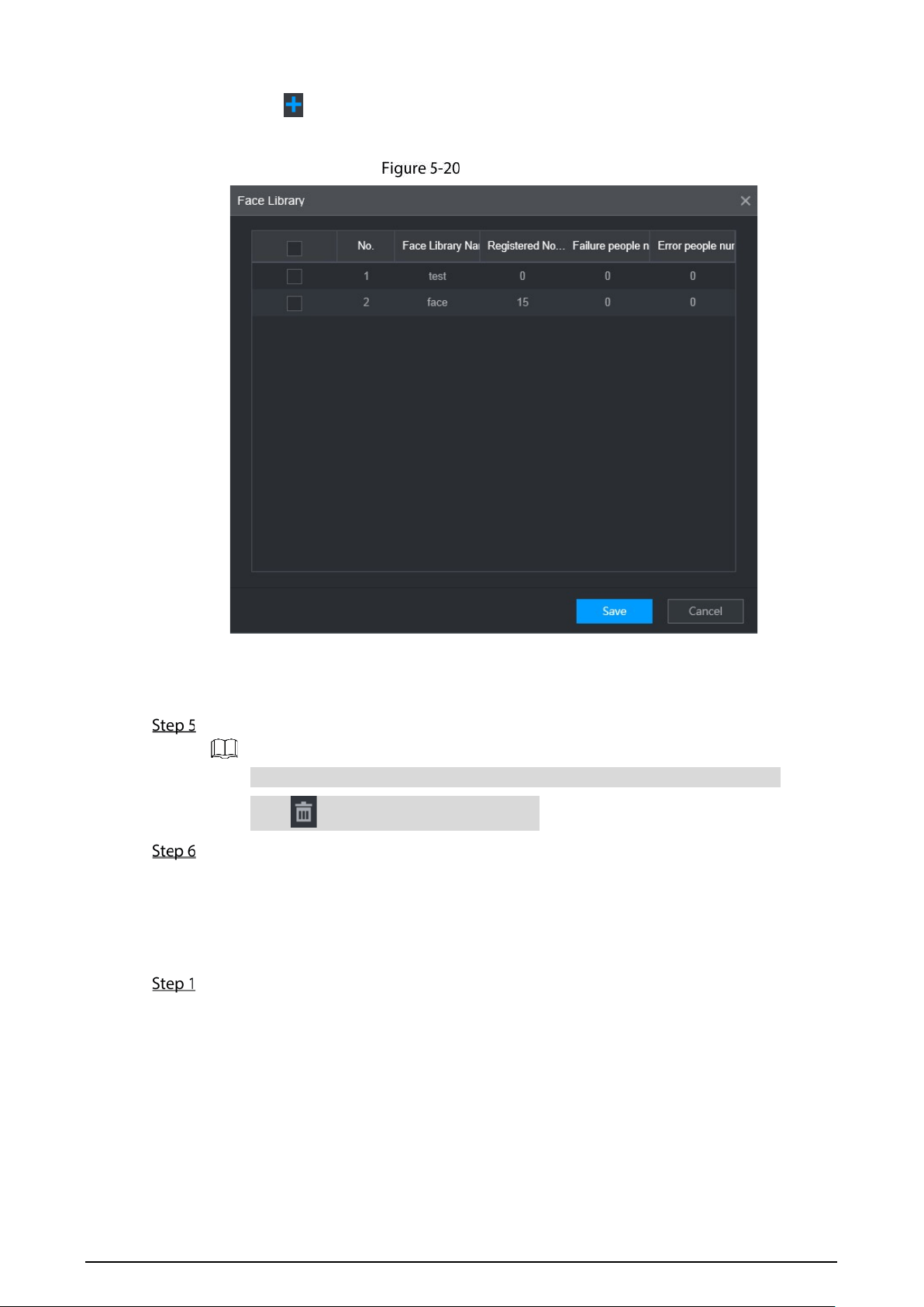
79
1) Click .
The Face Library interface is displayed. See Figure 5-20.
Face library
2) Select one or more face libraries to be added.
3) Click OK.
The face library information is displayed.
(Optional) Double-click the number under Similarity to modify the face matching similarity.
The lower the similarity, the higher the probability of triggering face matching.
Click to delete the added face library.
Click OK.
5.2.1.2.3 AI Search
The system can search and compare the faces in the videos and the faces in the face library
and play back the recordings.
On the main web interface, select AI > AI Search > Face Matching.
The Face Matching interface is displayed. See 错误!未找到引用源。.
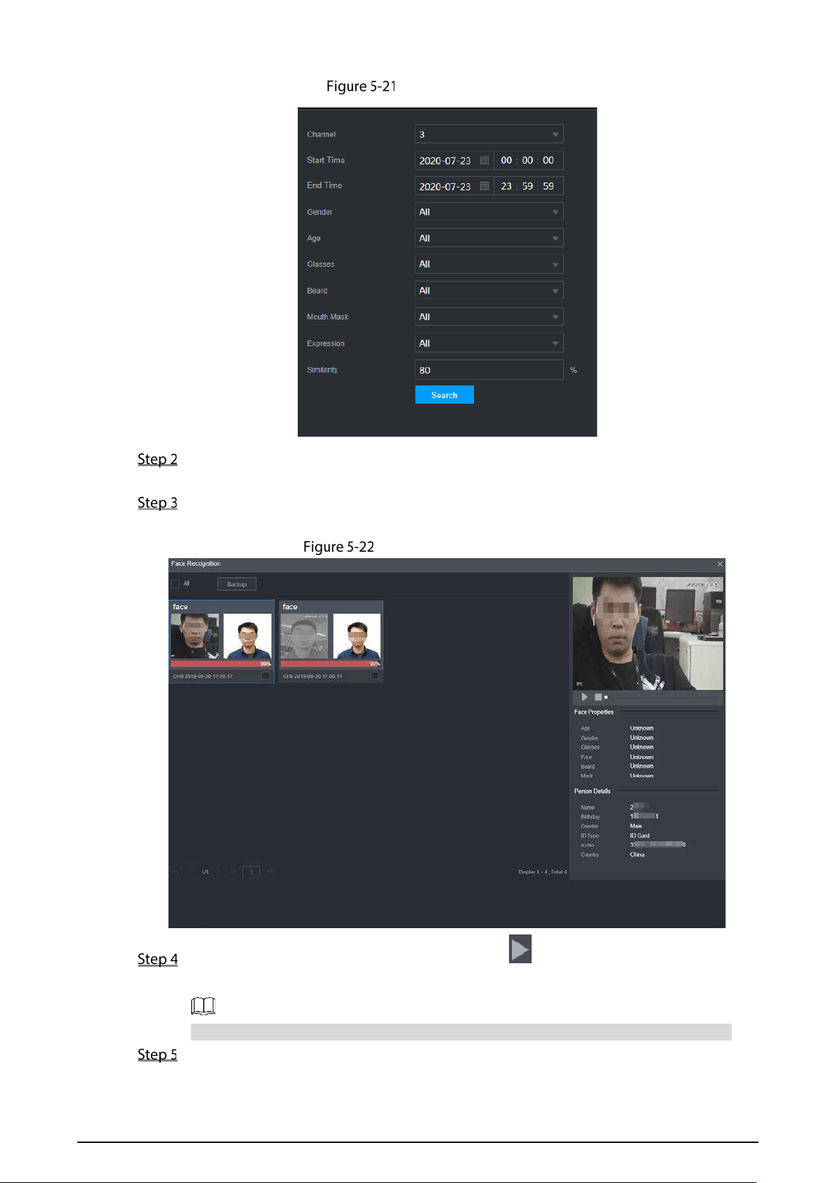
80
Face matching (3)
Select the channel, start time and end time, and select face matching details (such as gender,
age, glasses, beard, face mask, expression and similarity) as needed.
Click Search.
The search results are displayed. See Figure 5-22.
Attribute search result (2)
Select the face image you need to view, and click . The system starts playing back the
video file that the image belongs to.
Double-click the playback interface to switch between full screen and small screen.
(Optional) Back up files.
1) Select files and click Backup.
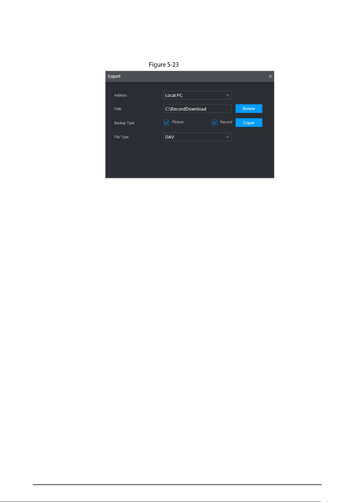
81
The Export interface is displayed. See Figure 5-23.
2) Select the backup address, path, backup type and file type, and click Export.
File backup is completed.
Export (2)
5.2.2 Active and Safe Drive
5.2.2.1 Configuring ADAS Function
Introduction
ADAS (Advanced Driving Assistance System) alarms mainly include forward collision warning, lane
departure warning and headway monitoring warning. The Recorder can monitor the road conditions
in front of the vehicle and generate an alarm through the front-view monitoring camera. After being
triggered, these alarms require voice broadcast by means of TTS and need to be uploaded to the
platform. After these alarms are triggered, the system will generate voice broadcast and report to the
platform.
Preparation
Access to cornering lamp signal in advance: Alarm Input_2 (turn left), Alarm Input_3 (turn
right). After the cornering lamp of the vehicle is turned on, no Lane Departure alarm will be
triggered.
Config: Driver assistance relies on the camera installation location, and cannot be used
until the calibration is completed. Try to install the camera in the middle of the windshield.
When configuring parameters, measure the width of the vehicle, the height of the camera,
and the distance from the camera to the vehicle head in advance. After the vehicle travels
for a certain period of time, the device will automatically calibrate the position.
Matching Product
The front view monitoring camera is a camera used to monitor the conditions in front of the vehicle.
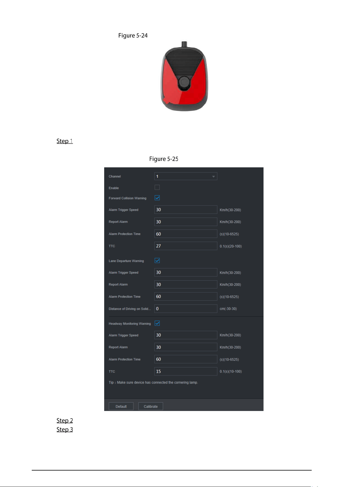
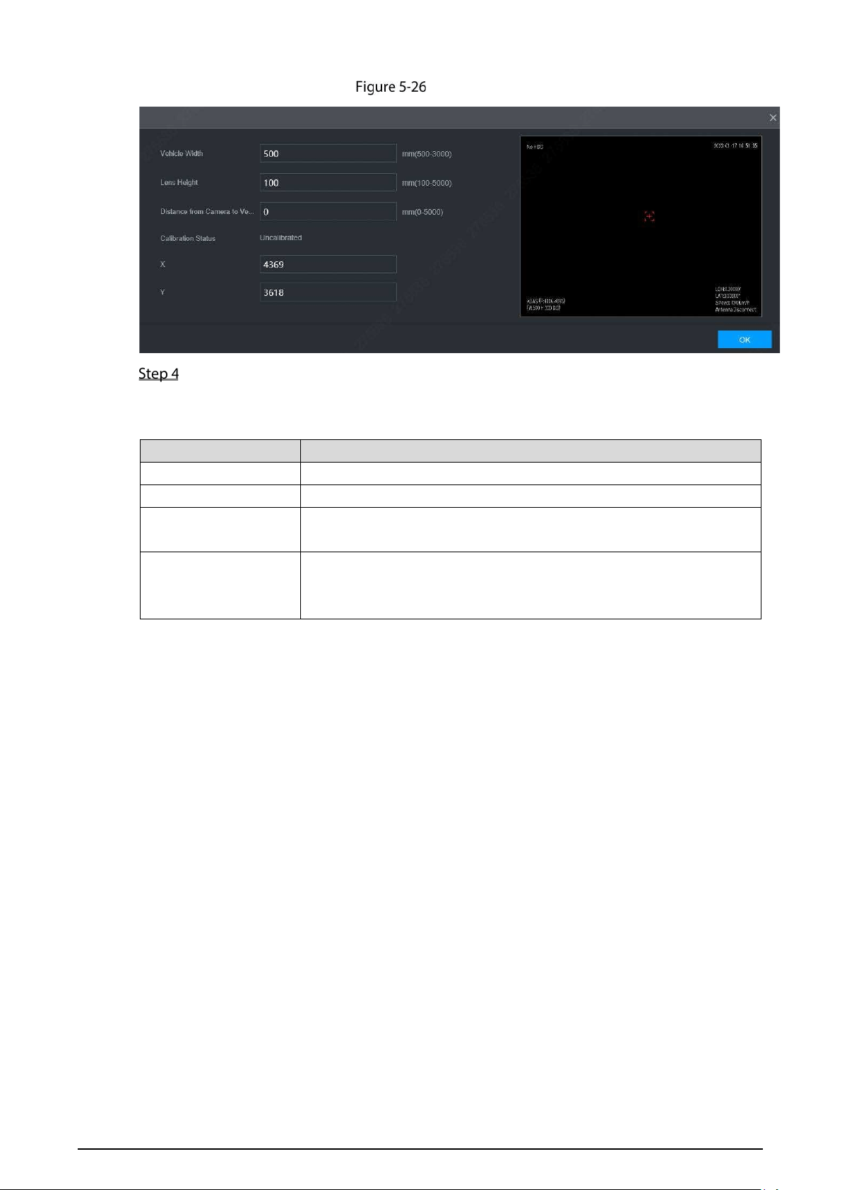
83
Calibrate
Enter the vehicle width, the lens height and the distance from the camera to the vehicle
head, and click OK to complete the calibration. For details, see Table 5-6
Table 5-6 Calibration parameters
Parameter Description
Vehicle width The distance between the outside of two front wheels of the vehicle.
Lens height Height of lens from the ground.
Distance from Camera
to Vehicle Head
Distance between lens and vehicle head
X, Y
The X value represents the installation yaw angle of the camera, and the
range is 2958-5233; The Y value represents the installation pitch angle of
the camera, and the range is 3872-4320.
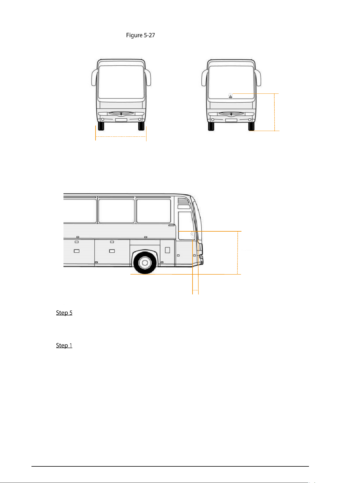
84
Distance measurement
Click OK.
Configuring ADAS Parameters
On the main WEB interface, select AI > Parameters > ADAS.
Lens height
Vehicle width
Distance from camera to vehicle head
Lens height
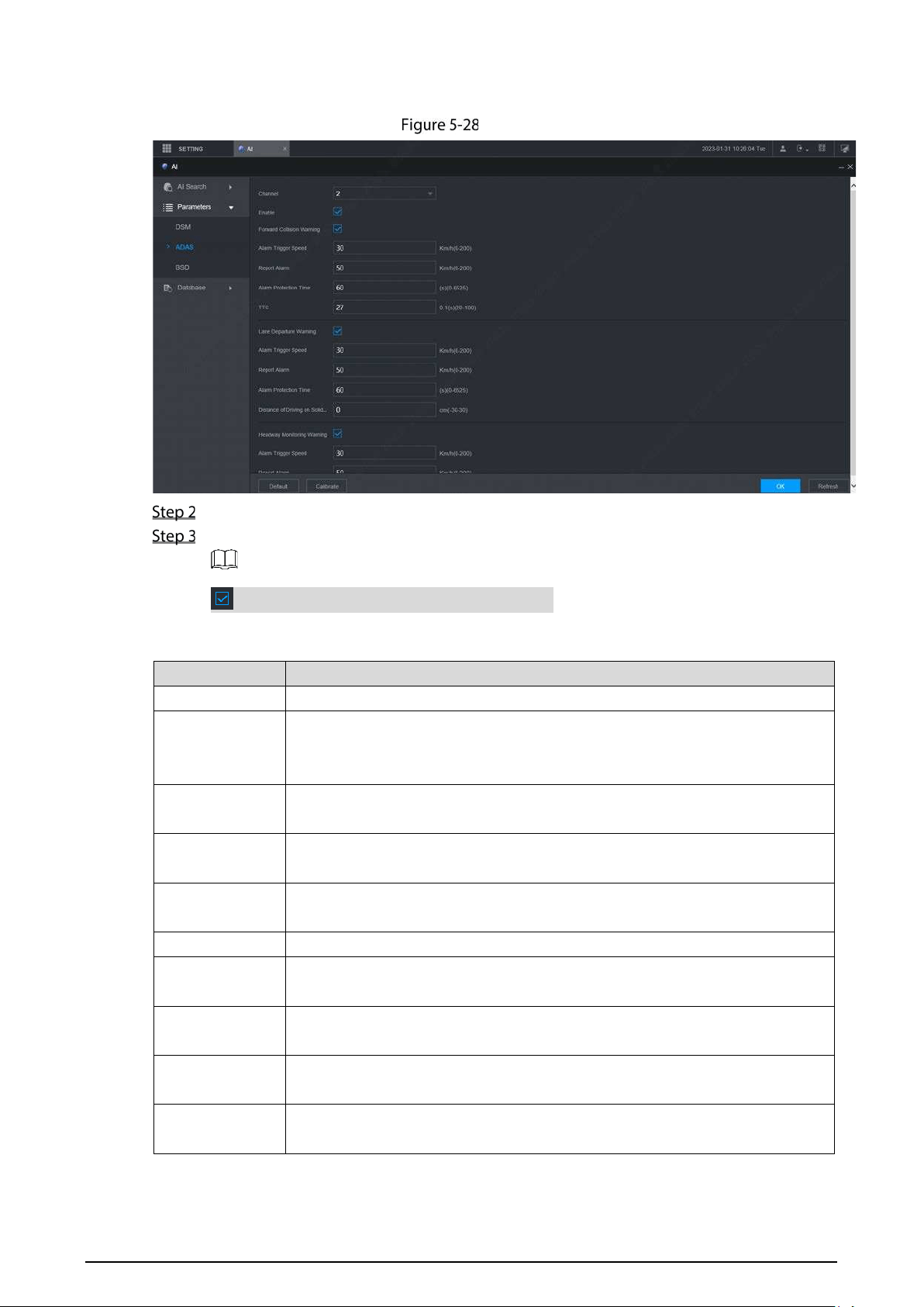
85
The ADAS interface is displayed.
ADAS
Select Enable and click OK.
Configure parameters. For details, see Table 5-7.
means the corresponding alarm is enabled.
Table 5-7 ADAS parameter description
Parameter Description
Channel ADAS is fixed to channel 2.
Forward
collision
warning
Gives out warning if it is possible to collide with the vehicle in front.
Alarm trigger
speed
The speed at which the Forward Collision Warning is triggered: The range is
30km/h–200km/h.
Report alarm
The speed at which the Forward Collision Warning is uploaded to the platform:
The range is 0km/h–200km/h.
Alarm
protection time
Continuous alarm time: The range is 0s–6525s.
TTC Time to collision: The range is 2s–10s.
Lane departure
warning
Gives out warning when the vehicle directly changes the lane without turning
on the left or right cornering lamp.
Alarm trigger
speed
The speed at which the Lane Departure Warning is triggered: The range is
0km/h–200km/h.
Alarm upload
The speed at which the Lane Departure Warning is uploaded: The range is
0km/h–200km/h.
Alarm
protection time
Continuous alarm time: The range is 0s–65536s.

86
Distance of
driving on solid
line
Set the distance of driving on solid line: The range is -30cm–30cm.
Headway
Monitoring
Warning
Gives out warning when the vehicle is too close to the vehicle in the front.
Alarm trigger
speed
The speed at which the Headway Monitoring Warning is triggered: The range is
0km/h–200km/h.
Report alarm
The speed at which the Headway Monitoring Warning is uploaded: The range
is 0km/h–200km/h.
Alarm
protection time
Continuous alarm time: The range is 0s–6525s.
TTC Time to collision: The range is 0s–10s.
Click OK.
5.2.2.2 Configuring DSM Function
Introduction
DSM (Driver Status Monitor) alarms mainly include drowsy driving, distracted driving, calling
when driving, driver not in position, wearing infrared-blocking sunglasses, smoking when
driving, and camera being shielded. The recorder can monitor and alarm unsafe driving
behaviors through the driver monitoring camera. After being triggered, these alarms require
voice broadcast by means of TTS and need to be uploaded to the platform.
Matching Product
The driver monitoring camera is used to analyze the abnormal driving status of the driver. It can
identify the unsafe driving behaviors of the driver during the driving process, such as drowsy driving,
calling, distracted driving, smoking, etc., and generate an alarm by detecting the changes in the
driver's eyes, face or behavior.
Driver Monitoring Camera
Configuring DSM Parameters
On the main web interface, select AI > Parameters > DSM.
The DSM interface is displayed. See Figure 5-30.
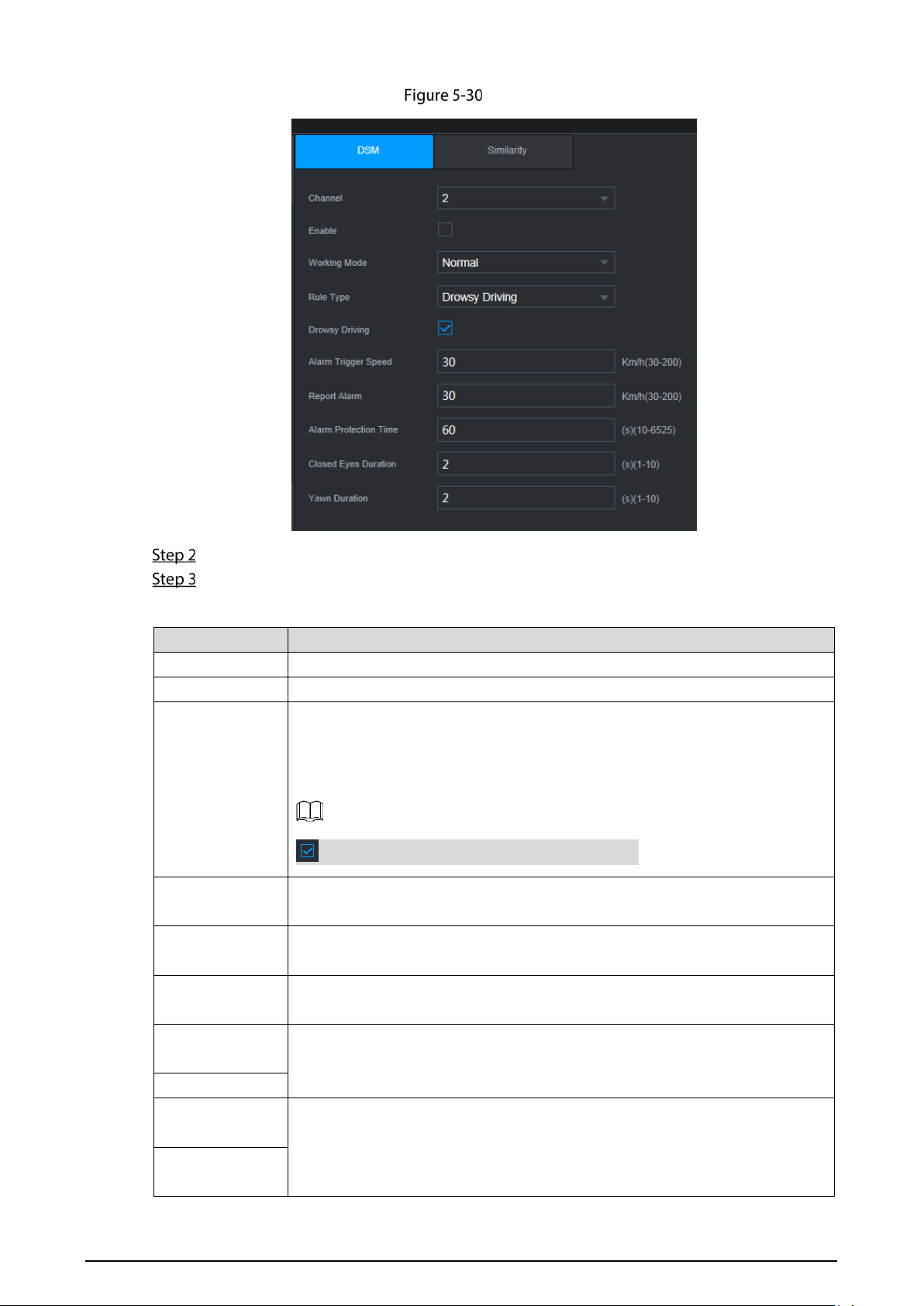
87
DSM
Click Enable to enable the DSM alarm.
Configure parameters. For details, see Table 5-8.
Table 5-8 DSM parameter description
Parameter Description
Channel The DSM is fixed to channel 1.
Working mode Vehicle working modes include normal mode and test mode.
Rule type
For alarm rules, you can select drowsy driving, distracted driving, calling when
driving, driver not in position, wearing infrared-blocking sunglasses, smoking
when driving, lens tempering, unbelted alarm, ID exception and substitution
driving (not the correct driver).
means the corresponding alarm is enabled.
Alarm trigger
speed
The speed at which the alarm is triggered: The range is 0 km/h–200 km/h.
Report alarm
The speed at which the alarm is uploaded to the platform: The range is 0
km/h–200 km/h.
Alarm protection
time
Continuous alarm time: The range is 100s–6525s.
Closed eyes
duration
Setting is necessary when the rule type is Drowsy Driving: The range is 1s–
10s.
Yawn duration
Duration of
lowering head
Setting is necessary when the rule type is Distracted Driving: The range is 1s–
10s.
Duration of
looking around
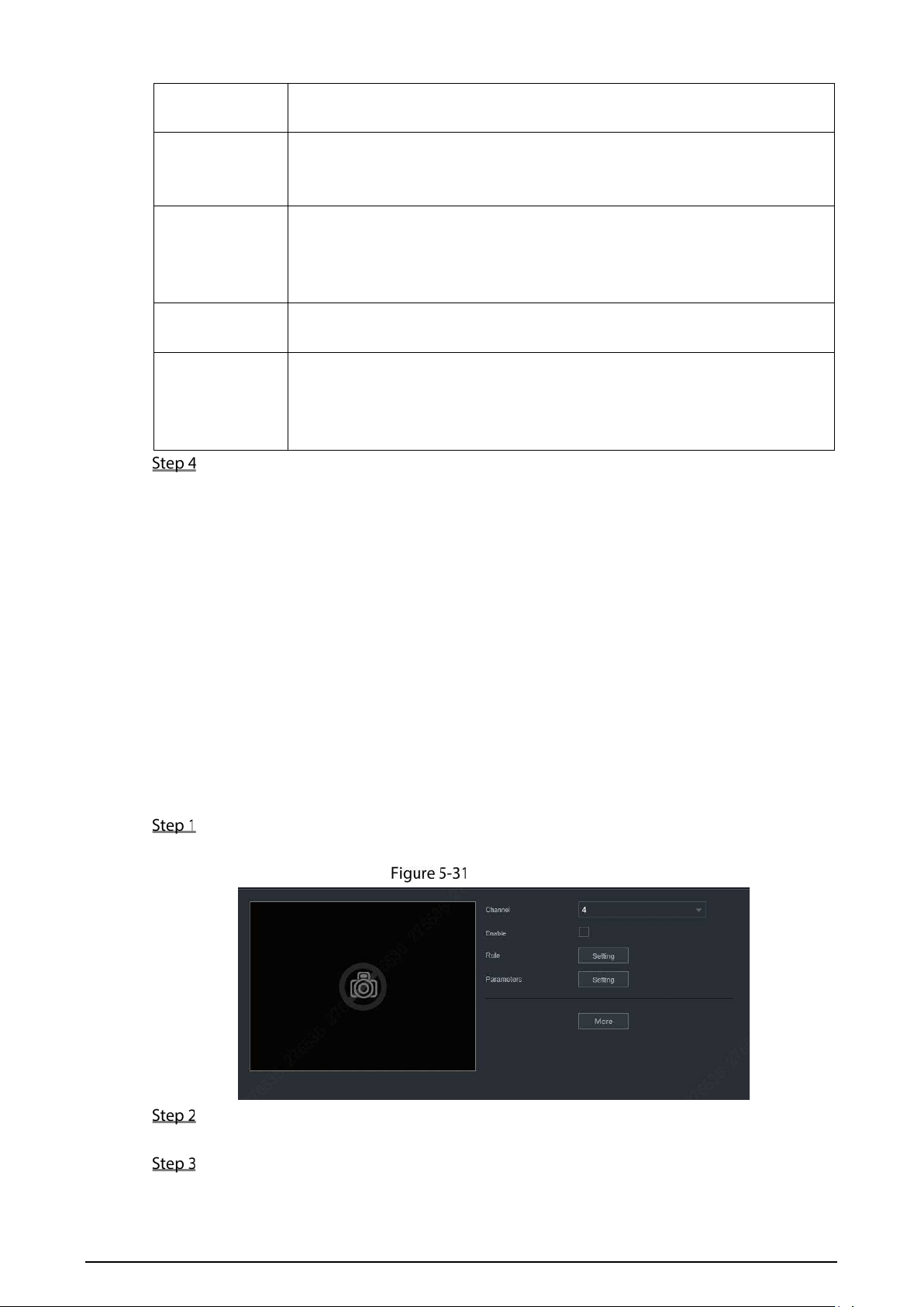
88
Duration of
calling
Setting is necessary when the rule type is Calling When Driving: The range is
1s–10s.
Duration of
driver not in
position
Setting is necessary when the rule type is Driver not in Position: The range is
2s–10s.
Duration of
wearing
infrared-blocking
sunglasses
Setting is necessary when the rule type is Wearing Infrared-Blocking
Sunglasses: The range is 1s–10s.
Duration of
smoking
Setting is necessary when the rule type is Smoking When Driving: The range
is 1s–10s.
Duration of
acceleration
when camera is
shielded
Setting is necessary when the rule type is Camera Being Masked: The range is
1s–10s.
Click OK.
5.2.3 Number Plate
Cameras connected to the Recorder can take snapshots of car plates. On the Recorder configure the
area where number plate recognition works. Also, you can search for the car plate and play the
corresponding video recording.
5.2.3.1 Number Plate Detection
Configure number plate detection region and its alarm settings.
Procedure
On the main interface, select AI > Parameters > Plate No..
The Plate No interface is displayed.
Plate No.
Select the channel in which you want to monitor the car plate and select Enable to enable
the plate recognition function.
Configure parameters, see Table 5-9.
Table 5-9 Plate No. Parameters
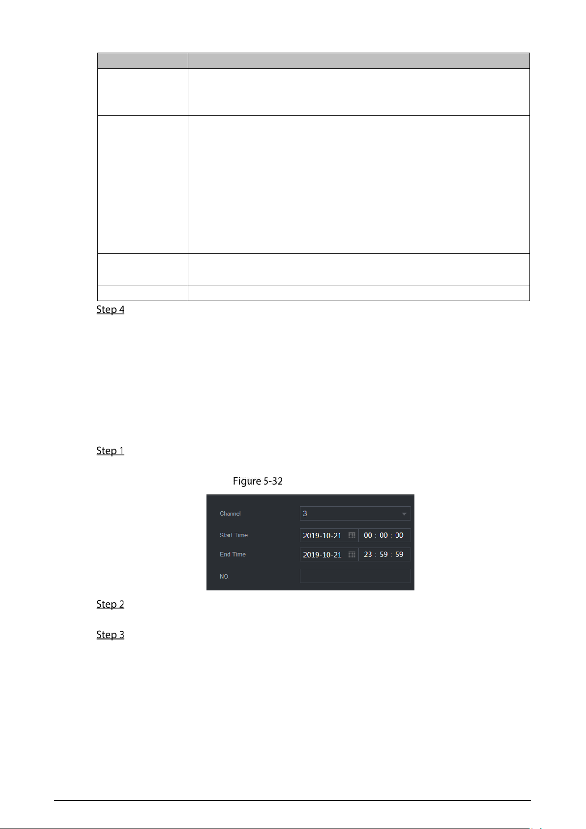
89
Parameter Description
Rule
1.
Click Setting next to Rule.
2. Drag the yellow box four corners to adjust the recognition function size
or shape.
Parameters 1.
Click Setting next to Parameters.
2. Configure more plate recognition settings.
Sensitivity: The larger the value, the easier plates will be to be
detected.
Interval: Within the interval, camera will not take snapshot of one
plate twice.
Frame Rate: Video image frames per second.
Plate: When the plate state is blurry in the plate recognition region,
use this state information automatically.
Buzzer
Click More Setting and select Buzzer. Set buzzer alarm to give out
reminding.
Log
Click More Setting and select Log to record plate recognition.
Click OK.
5.2.3.2 Plate No. Recording Search
Search time (or search plate number plus time if you know the plate No.) for the corresponding video
recording for you to play and check.
Procedure
On the main interface, select AI > AI Search > Plate No..
The Plate No. interface is displayed. See Figure 5-32.
Searching plate
Enter a channel, start time, end time. (And enter plate number if you know the plate
number.)
Click Smart Search.
Results are displayed. See Figure 5-33.
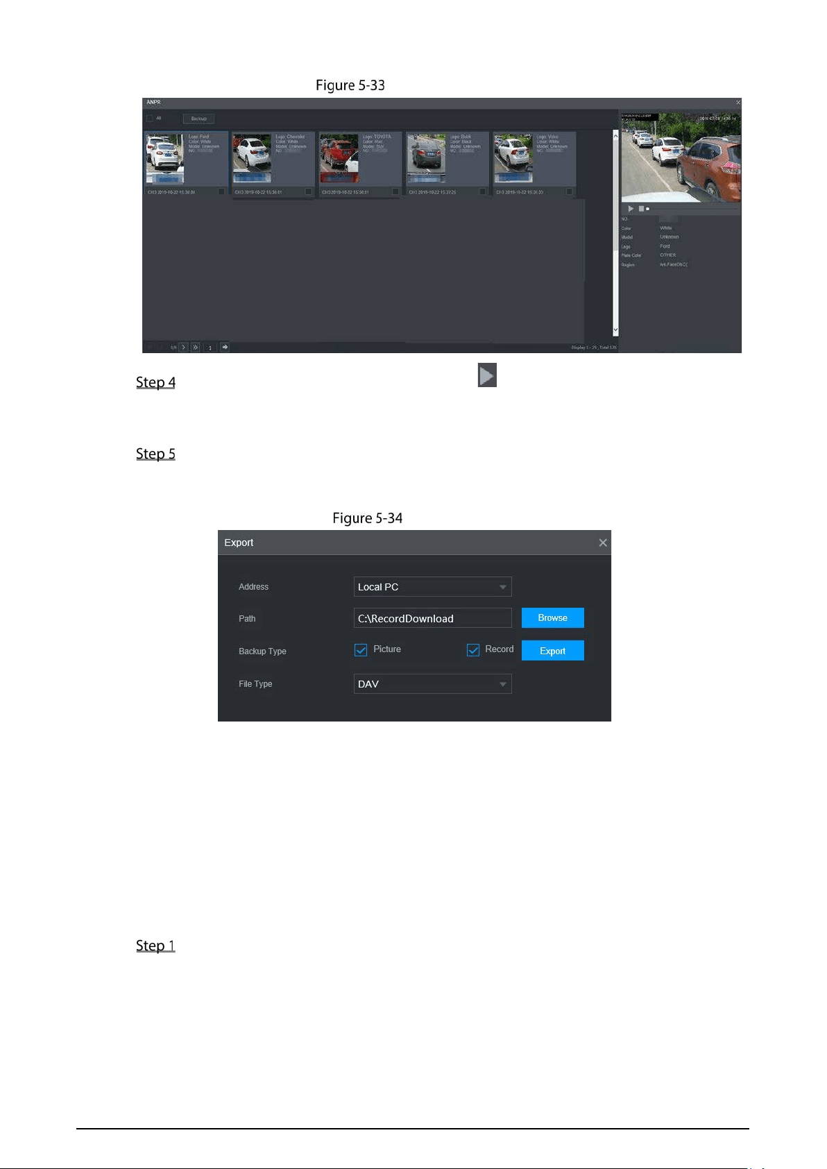
90
Smart search results
Select the plate item you want to view. Click to play corresponding video recording.
Double-click video recording image to switch playing between full screen and partial
screen.
Export files.
1) Select files and click Copy.
The Export interface is displayed. See Figure 5-34.
Exporting files
2) Select Address, Path, Backup Type and File Type. Then click Export.
5.2.4 Passenger Flow Measurement
The system can count the number of passengers in and out at each stop. The alarm in channels are
connected to the doors for detecting door open and close. For example, if the alarm in Channel 3 is
connected to the front door and bound to Camera 3 (overlooking the front door), when the door
opens, Camera 3 will start counting the number of people, and when the door closes, the counting
stops. The people counting data starts from 0 at each stop.
On the main interface, select AI > Parameters > Passenger Flow Measurement.
The Passenger Flow Measurement interface is displayed.
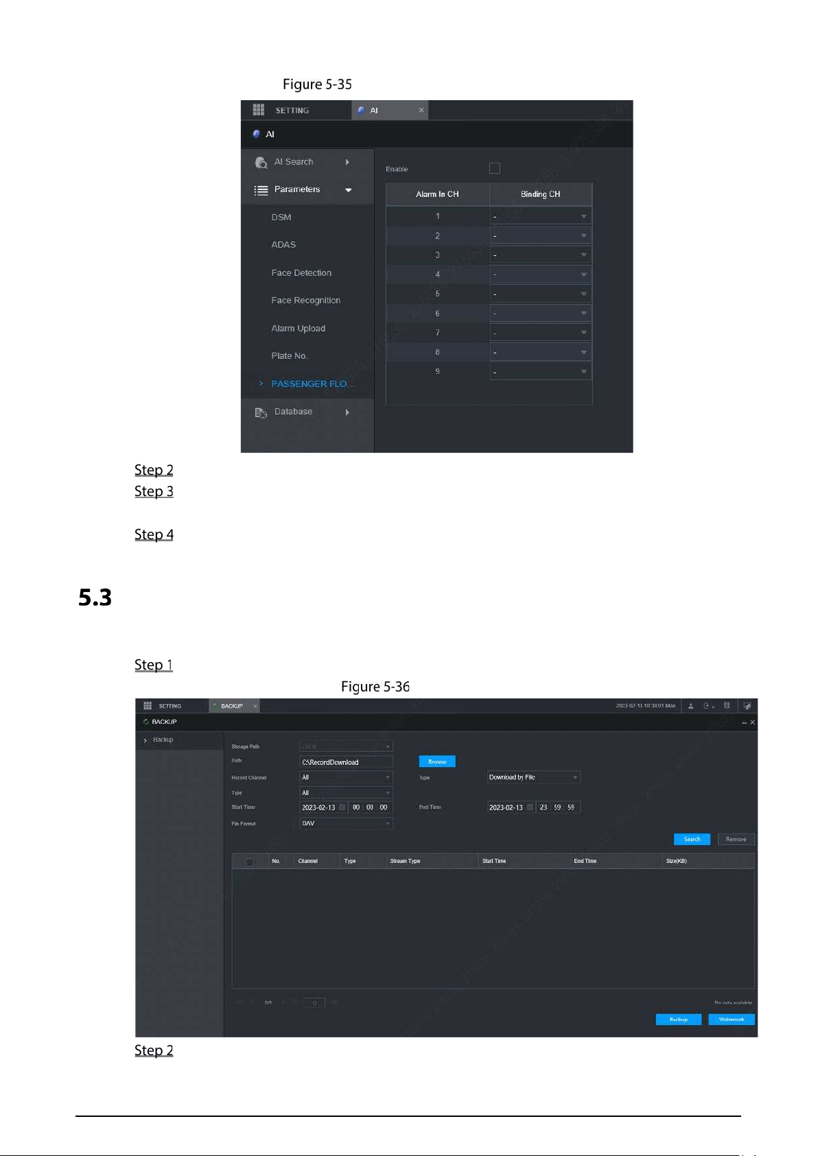
91
Passenger Flow Measurement
Select the Enable check box to enable the function.
Select the specific camera channel from the Binding CH column to bind to the
corresponding alarm in channel in the Alarm In CH column.
Click OK.
Backing up File
You can back up video recordings and images.
On the main web interface, click BACKUP.
Backup (1)
Configure parameters. For details, see Table 5-10.
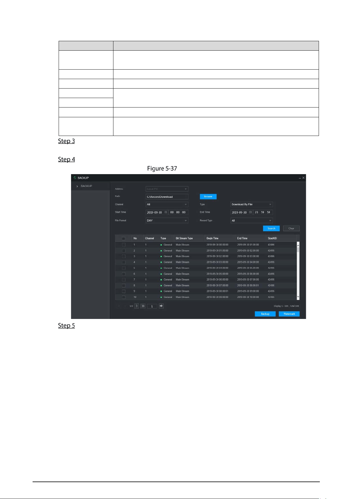
92
Table 5-10 Backup parameters
Parameter Description
Path
File backup path is C://RecordDownload by default.
Click Browse to set the backup path as needed.
Record Channel Select the channel you want to do the backup for.
Download Type Select the backup type, including download by file and download by time.
Start time
Set the file backup period.
End time
File Format Select the backup file format, including DAV and MP4.
Record type
Select the record type, including external alarm, motion detect, all alarms,
normal record, picture, and all.
Click Search.
The obtained files are displayed.
Select the file that you want to back up, and click Backup.
Backup (2)
Click View Download.
The Download interface is displayed. See Figure 5-38.
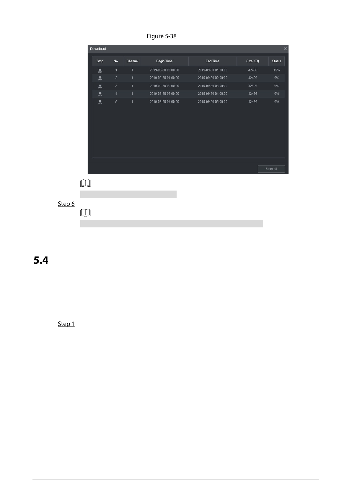
93
Download
Click Stop all to stop downloading.
(Optional) Select the file that you want to verify, and click Watermark.
Watermark can be used to verify whether the record file is falsified.
The verifying progress and result are displayed.
Configuring Display Output Settings
You can configure device tour and video mirror settings.
5.4.1 Tour Settings
On the main web interface, select DISPLAY > Tour Setting.
The Tour Setting interface is displayed.
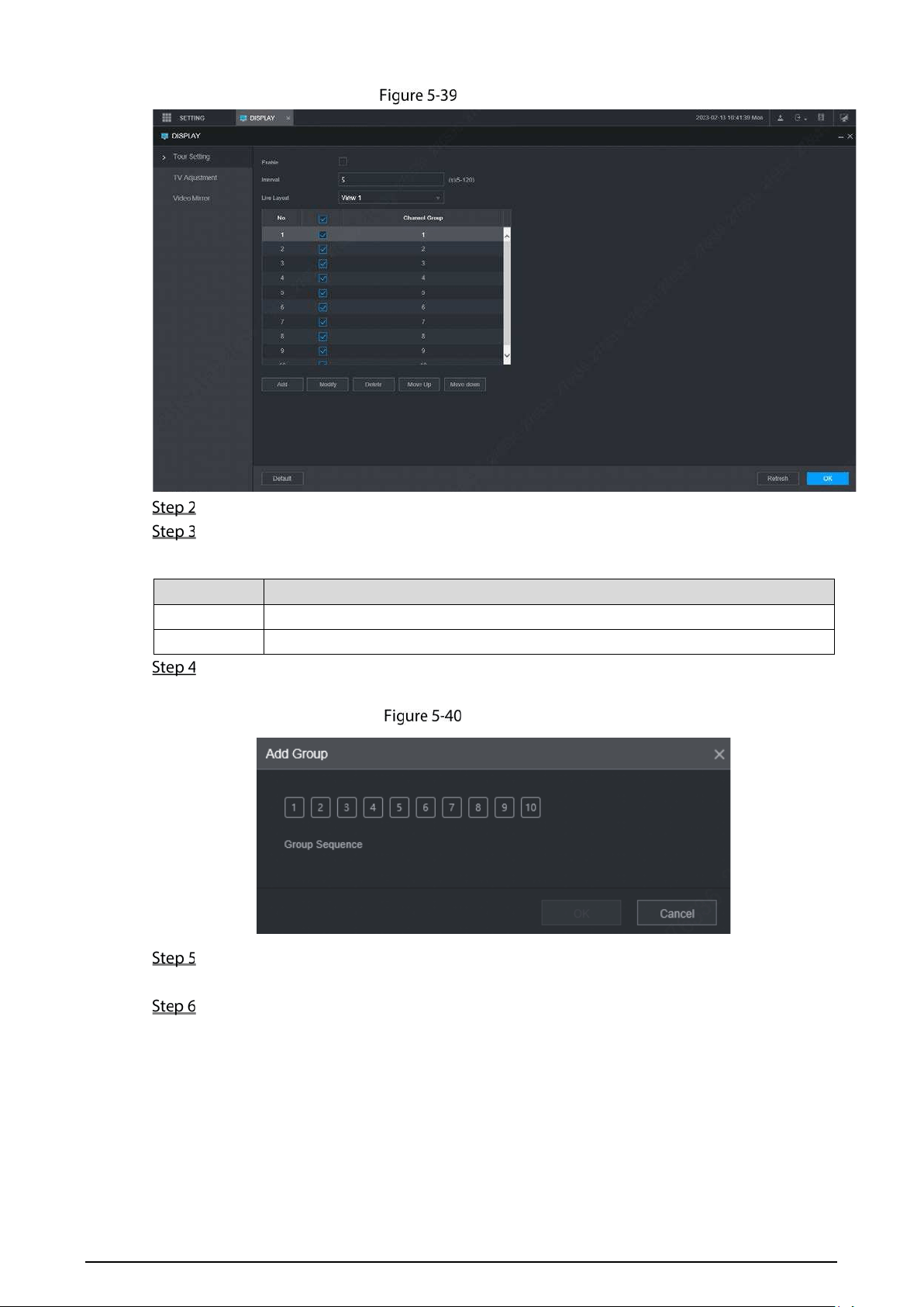
94
Tour Setting
Click Enable to enable the tour settings.
Configure parameters. For details, see Table 5-11.
Table 5-11 Tour parameters
Parameter Description
Interval Set the tour interval.
Window split The window split modes include single screen and 4-screen.
Click Add.
The Add Group interface is displayed.
Add group
Select the channel and click OK.
Repeat Step 4–Step 5 to add multiple channel groups in tour.
Click OK.
Select a channel group, and click Modify to modify the channel group and channel
sequence.
Select a channel group, and click Delete to delete it.
Select a channel group, and click Move up or Move down to modify the channel
group sequence.
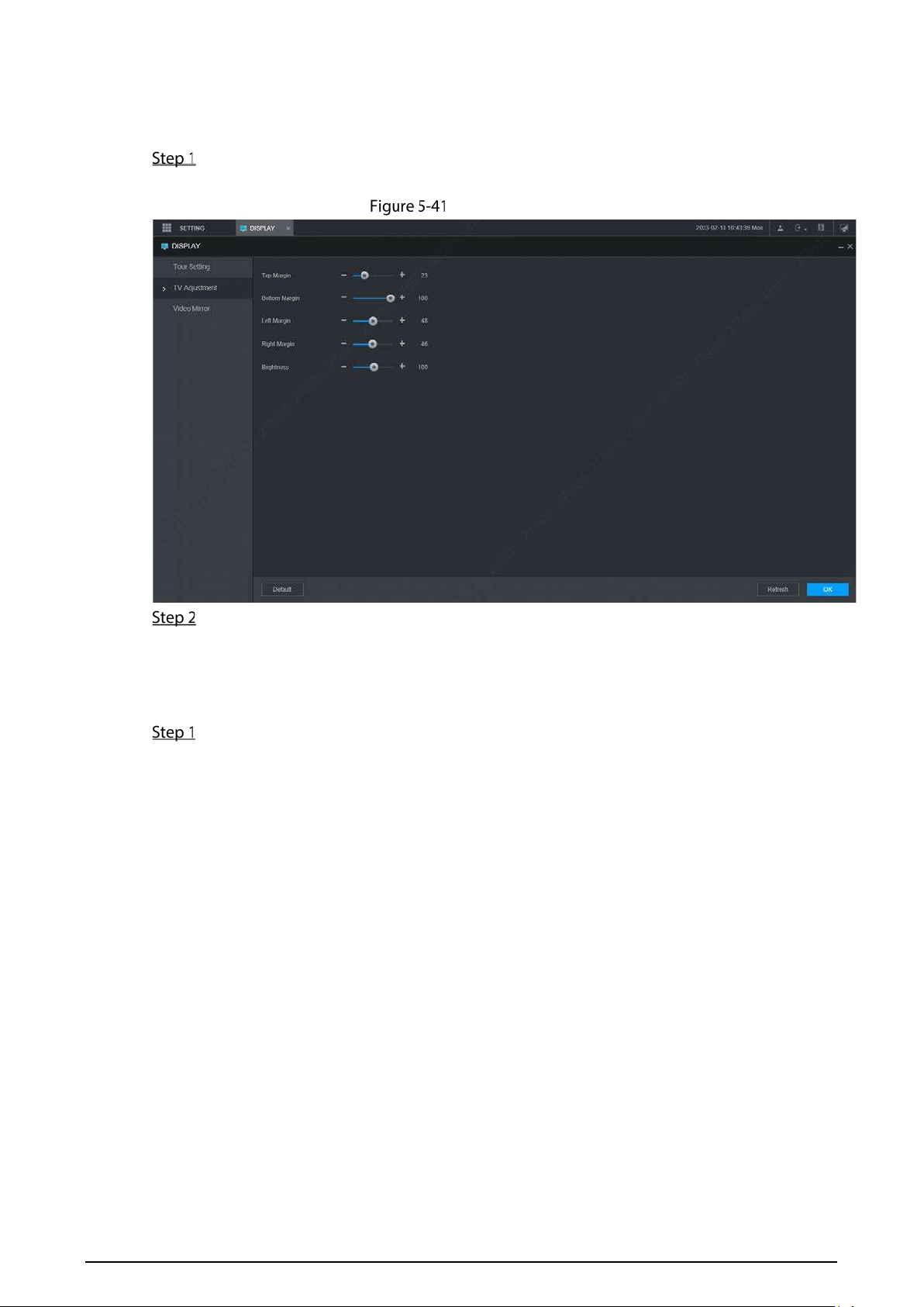
95
5.4.2 TV Adjustment
On the main web interface, select DISPLAY > TV Adjustment.
The TV Adjustment interface is displayed.
TV Adjustment
Drag the adjustment button to adjust the margins and brightness of the picture
5.4.3 Video Mirror Settings
On the main web interface, click DISPLAY > Video Mirror.
The Video Mirror interface is displayed. See Figure 5-42.
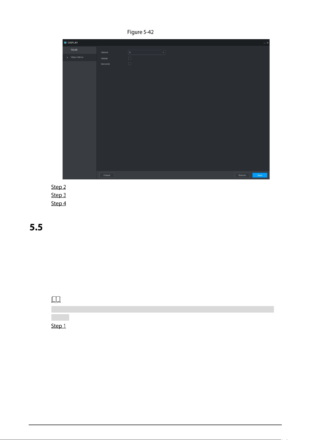
96
Video mirror
Select a channel.
Select a mirror mode. You can select Vertical or Horizontal.
Click OK.
Configuring Camera Parameters
You can set camera properties, encoding parameters, PTZ properties, and view PoE power
supply information.
5.5.1 Camera Properties
You can set up the camera property parameters of the channel.
Different cameras correspond to different property parameters. The actual parameters shall
prevail.
Select SETTING > CAMERA > Image.
The Image interface is displayed.

97
Image
Select a channel.
Configure parameters.
Table 5-12 Image property parameters
Parameter Description
Cable Type The cable type is fixed to coaxial.
Period
Select the period. There are two Periods for you.You should set up the Effective
Time for different periods.
Brightness
Adjusts the image brightness through linear mode. The bigger the value is, the +
brighter the image will become.
Contrast
Adjust the image contrast. The bigger the value is, the more obvious the contrast
between the light area and dark area will become.
Saturation
Adjusts the color darkness. Adjust the saturation according to the actual
situation. The bigger the value, the lighter the color of the image will become.
Hue
Adjusts the color hue. Adjust the hue according to the actual situation. The
bigger the value, the colder the color of the image will become.
Sharpness
Set the sharpness of picture edges. The bigger the value is, the more obvious the
image edge will become.
Hue
Adjusts the color darkness. Adjust the saturation according to the actual
situation. The bigger the value, the lighter the color of the image will become.
Color Mode
Select the color mode. There are 5 preinstall modes you can choose, or you can
set 4 custom modes for options. Preinstall modes includes Standard, Soft, Bright,
Vivid, Bank.
Click OK.
5.5.2 Encode Parameters
You can configure Encode, Snapshot, Overlay, and Storage Path.
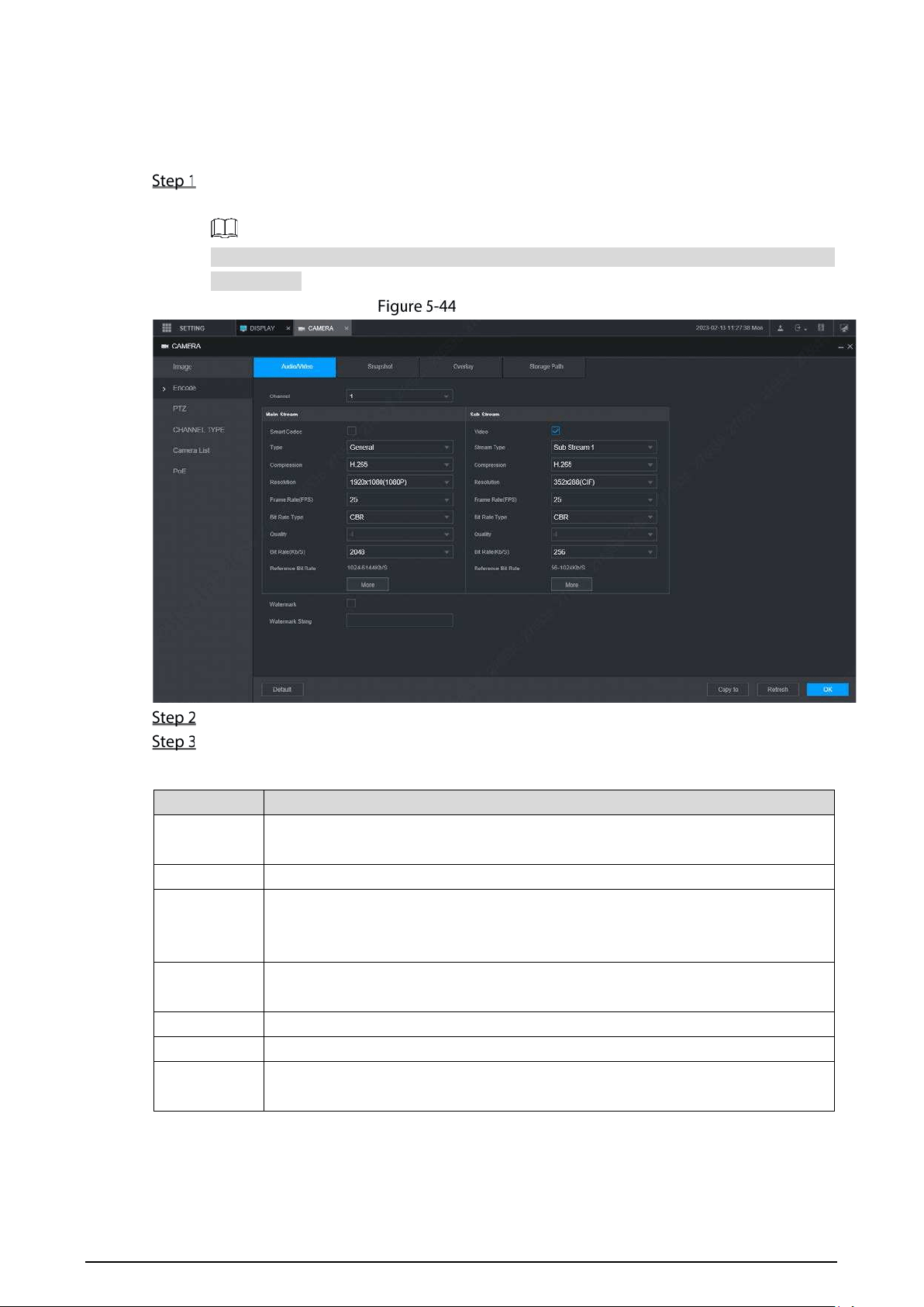
98
5.5.2.1 Encode
You can configure the encode settings for main stream and sub stream.
Select SETTING > CAMERA > Encode > Audio/Video.
The Audio/Video interface is displayed.
Encode parameters might be different depending on devices, and the actual product
shall prevail.
Audio/Video
Select a channel.
Configure parameters.
Table 5-13 Encode parameters
Parameter Description
Smart Codec
Enabling Smart Codec helps compress the images more and reduce the storage
space.
Video enable Enable the sub stream.
Record type
The record type of main stream is permanently fixed as General and cannot be
changed. General, motion detect and alarm use the general stream configurations
for recording.
Code-stream
type
Sub stream types.
Compression Compression mode.
Resolution The higher the video resolution, the better the image quality.
Frame rate
(FPS)
Configure the frames per seconds for videos. The higher the value, the smoother
and more vivid the image.
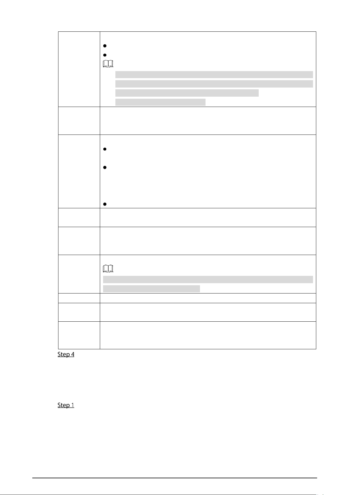
99
Bit rate type
You can select the bit rate type.
CBR: Constant Bit Rate, which changes around the configured value.
VBR: Variable Bit Rate, which changes along with environment.
It is recommended to select CBR when there might be only small
changes in the monitoring environment, and select VBR when there
might be big changes in the monitoring environment.
The main stream is fixed to VBR.
Quality
This parameter can be set only when Bit Rate Type is set to VBR.
The image quality level. There are six levels in total. The higher the value, the
better the image will become.
Bit rate (kb/s)
Configure the bit rate for main stream and sub stream.
When CBR is selected, select the bit rate according to the reference bit
rate, and the bit rate changes around the configured value.
When VBR is selected, select the upper limit value of bit rate according
to the reference bit rate, and the bit rate changes along with the
monitoring environment. But the maximum bit rate value changes around
the configured value.
Select
Customized
to configure bit rate value manually.
Reference bit
rate
The system recommends the optimal bit rate range according to the resolution
and frame rate settings.
Audio enable
Click More Setting to enable the audio.
If the corresponding check box is selected, the video recordings are audio and
video combined streams.
Audio
encoding
Select an audio encode format.
The parameters might be different depending on the model you purchased,
and the actual product shall prevail.
Audio source Source of audio.
Watermark
enable
Select the Watermark Enable check box to verify whether the video recording is
falsified.
Watermark
string
Enter the strings for verifying watermark. The default string is DigitalCCTV. The
watermark string can only consist of number, letter, underline (_), and hyphen (-),
and the maximum length is 127 characters.
Click OK.
5.5.2.2 Snapshot
You can configure the snapshot settings such as mode, size, quality, and interval.
Select SETTING > CAMERA > Encode > Snapshot.
The Snapshot interface is displayed.
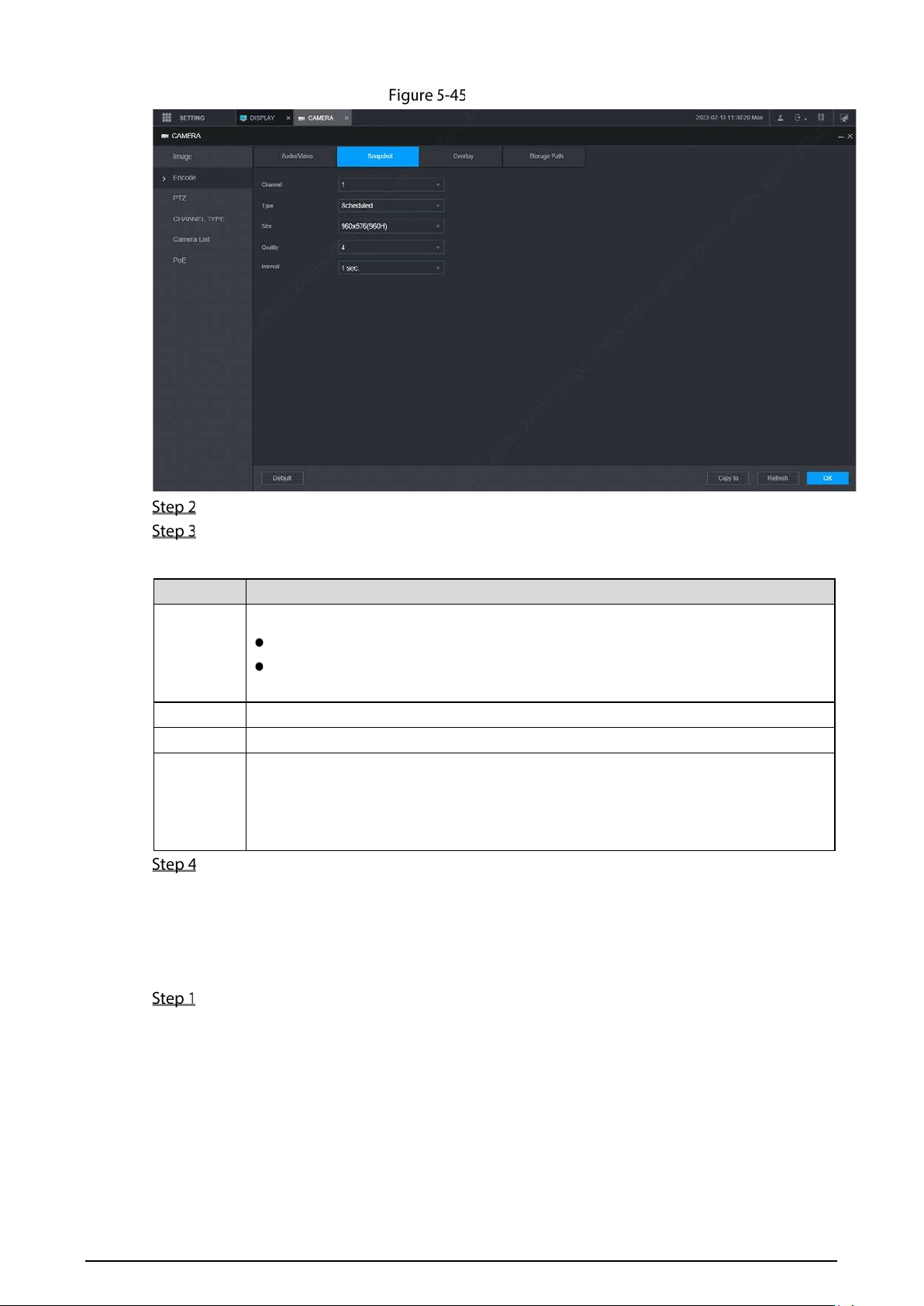
100
Snapshot
Select a channel.
Configure more parameters. See Table 5-14.
Table 5-14 Snapshot parameters
Parameter Description
Mode
Includes timing and event.
Timing: Take snapshots within the configured period.
Event: Take snapshots when alarms such as local alarm, video detection
and abnormality are triggered.
Size Select a resolution for the captured images.
Quality The image quality and there are six levels in total.
Interval
Interval of taking snapshots.
Select Customized to configure the snapshot interval for manually captured
snapshots. The maximum value you can set is 3600 seconds as an interval between
two snapshots.
Click OK.
5.5.2.3 Overlay
You can configure the title of video image overlay.
Select SETTING > CAMERA > Encode > Overly.
The Overlay interface is displayed.
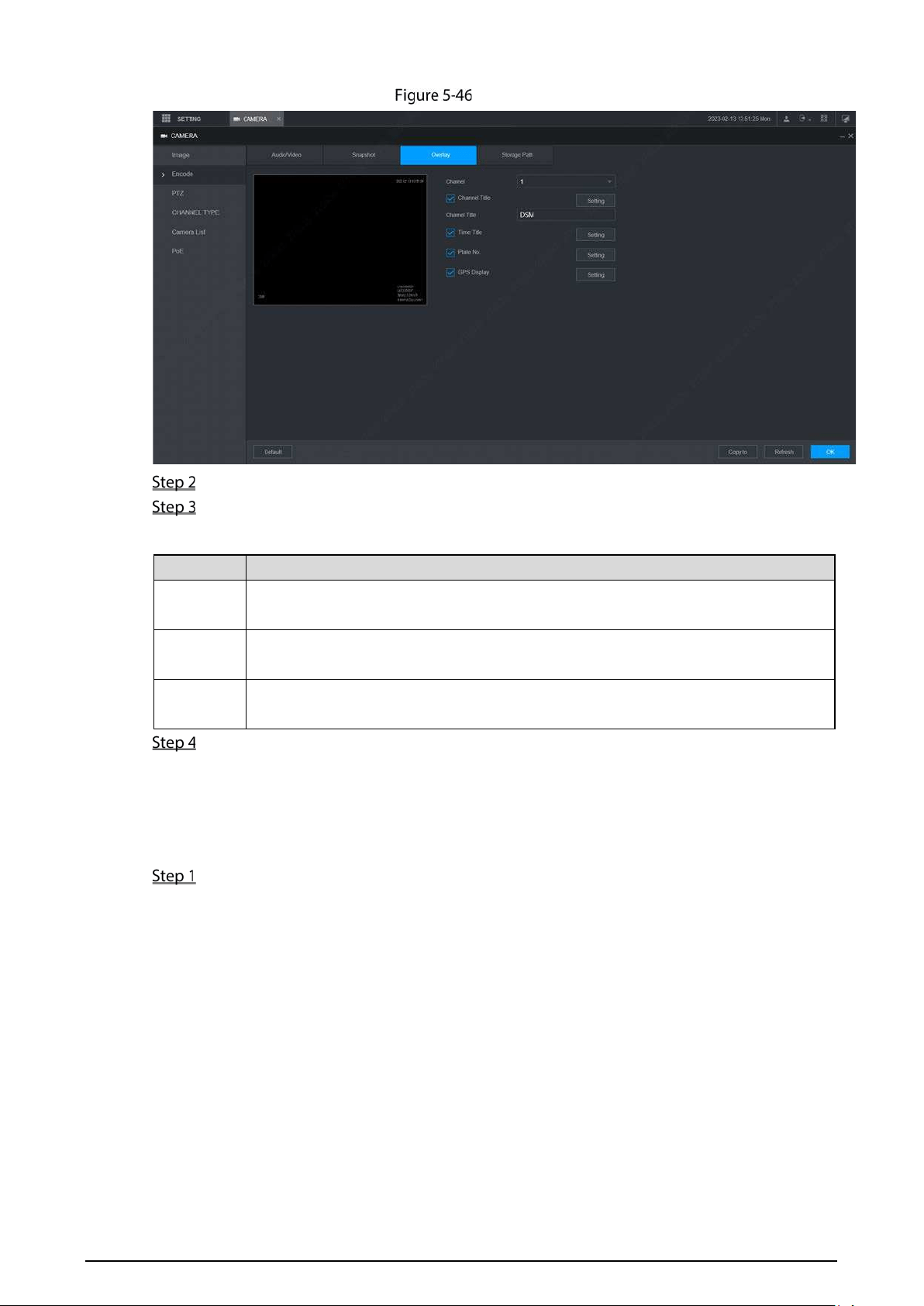
101
Overlay
Select a channel.
See Table 5-15.
Table 5-15 Overlay parameters
Parameter Description
Channel
title
Select Channel Title, and the Setting button is displayed. Then click Setting on the
right of the Channel Title, enter the channel title, and drag it to a proper location.
Time title
Select the Time Title check box, the Setting button is displayed. Then click Setting
on the right of the Time Title, and then drag it to a proper location.
GPS
display
Select the GPS Display check box, the Setting button is displayed. Then click
Setting on the right of the GPS Display, and then drag it to a proper location.
Click OK.
5.5.2.4 Storage Path
You can configure the storage path of captured snapshots and video recordings.
Select SETTING > CAMERA > Encode > Storage Path.
The Storage Path interface is displayed.
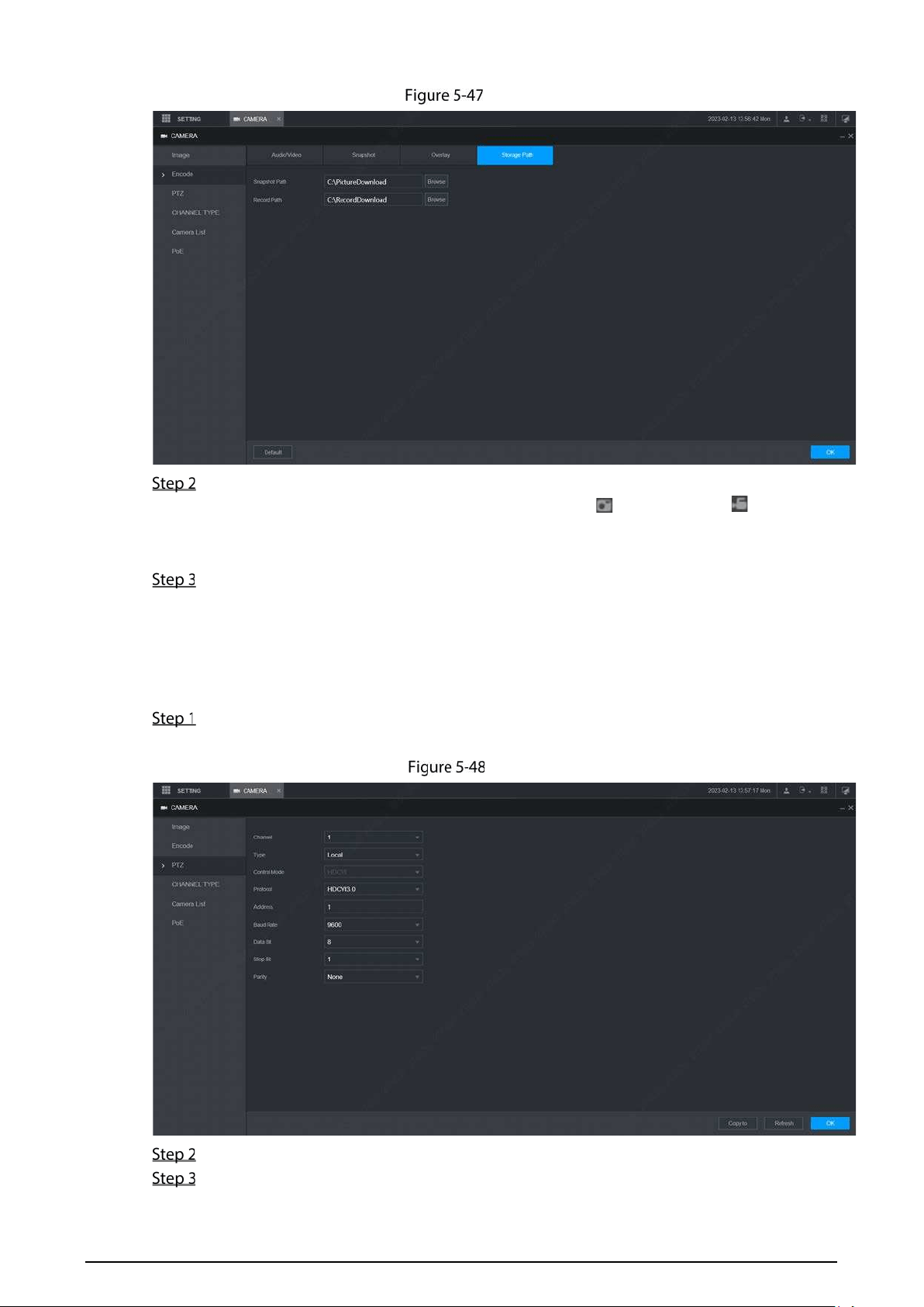
102
Path
Click Browse to select the save path for snapshots and recordings.
Images and recordings by using functions of snapshots and recordings on the Live
interface are saved in these two paths by default: C:\PictureDownload and
C:\RecordDownload.
Click OK.
5.5.3 PTZ
You can configure the corresponding PTZ of the device channel.
Select SETTING > CAMERA > PTZ.
The PTZ interface is displayed. See Figure 5-48.
PTZ
Select a channel.
Configure more parameters. See Table 5-16.
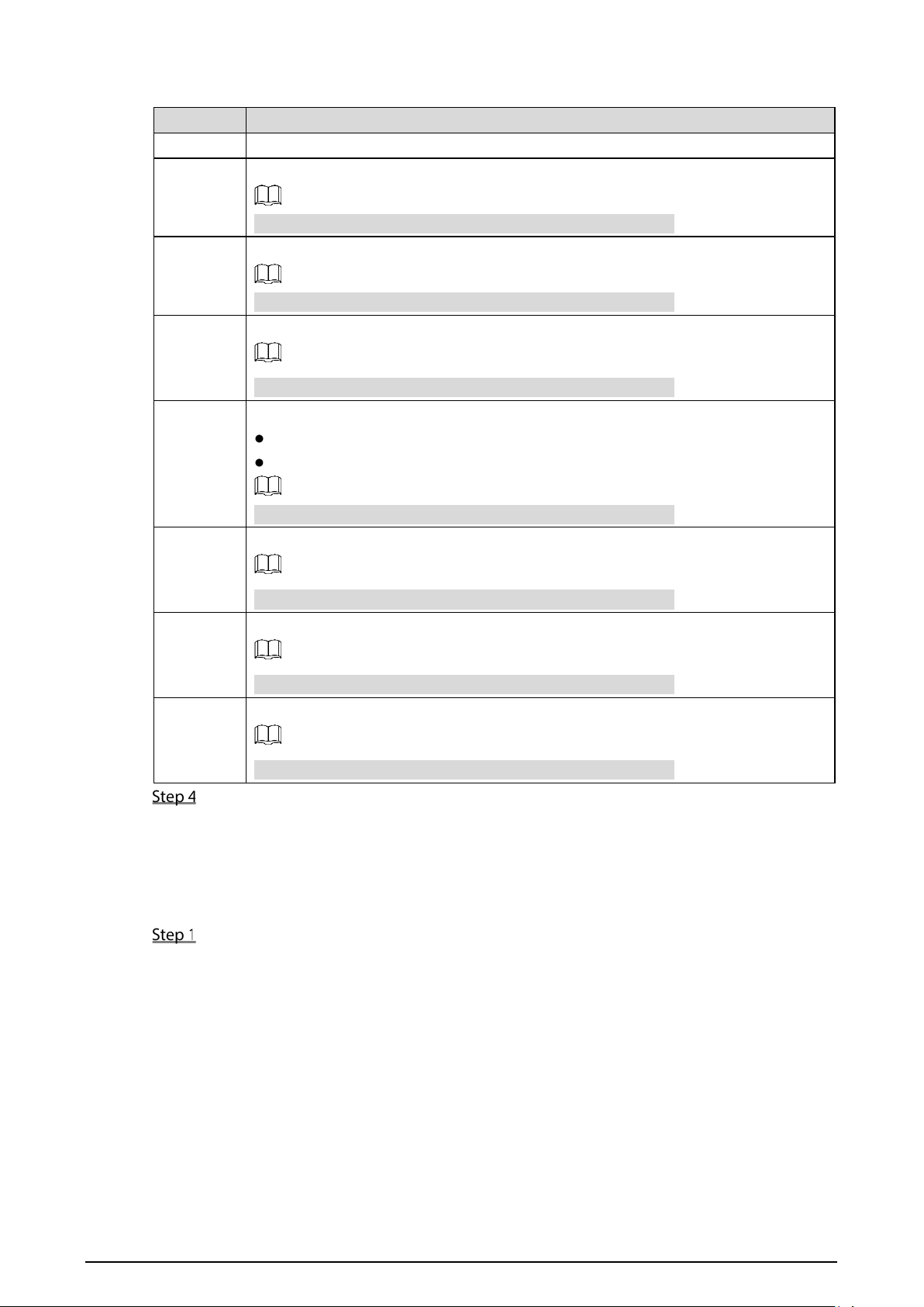
103
Table 5-16 PTZ parameters
Parameter Description
PTZ type Set the PTZ type, including local and remote.
Control
mode
PTZ controlling mode.
If
Local
is selected for PTZ type, configure this parameter.
Protocol
Select the PTZ protocol, including NONE, HDCVI3.0 and HDCCTV2.0.
If Local is selected for PTZ type, configure this parameter.
Address
Set the PTZ address.
If Local is selected for PTZ type, configure this parameter.
Baudrate
The times of signal changes on the transmission line within one time unit.
The default baudrate is 115200 for a console.
The default baudrate is 9600 for a vehicle light box.
If Local is selected for PTZ type, configure this parameter.
Data bits
Select a data bit. The options include 5, 6, 7, and 8.
If
Local
is selected for PTZ type, configure this parameter.
Stop bits
Select a stop bit. The options include 1, 1.5, and 2.
If
Local
is selected for PTZ type, configure this parameter.
Parity
Select a parity mode from None, Odd, Even, Mark, and Null.
If
Local
is selected for PTZ type, configure this parameter.
Click OK.
5.5.4 Channel Type
You can configure the corresponding type of the device channel.
Select SETTING > CAMERA >CHANNEL TYPE.
The CHANNEL TYPE interface is displayed.
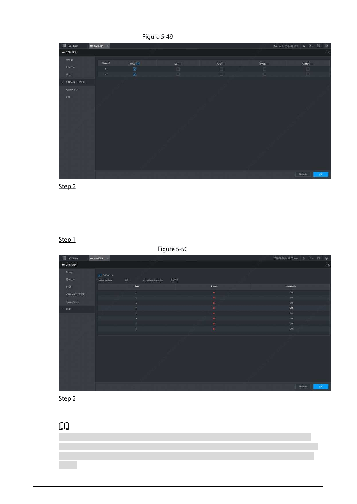
104
CHANNEL TYPE
Select channel type and click OK.
5.5.5 PoE
View the connection status of the PoE port and reset the camera.
Select SETTING > CAMERA > PoE in the main menu. The PoE interface is displayed.
PoE
Select PoE Reset, and click Apply to reset the camera with power but offline so that the
camera can be online. If the camera is still offline after reset for 3 times, the system will not
reset again.
When the total power of the cameras accessed through PoE exceeds the maximum power of the
device, the device will force the camera connected to the maximum port number to go offline until
the total power of the camera accessed through PoE does not exceed the maximum power of the
device.
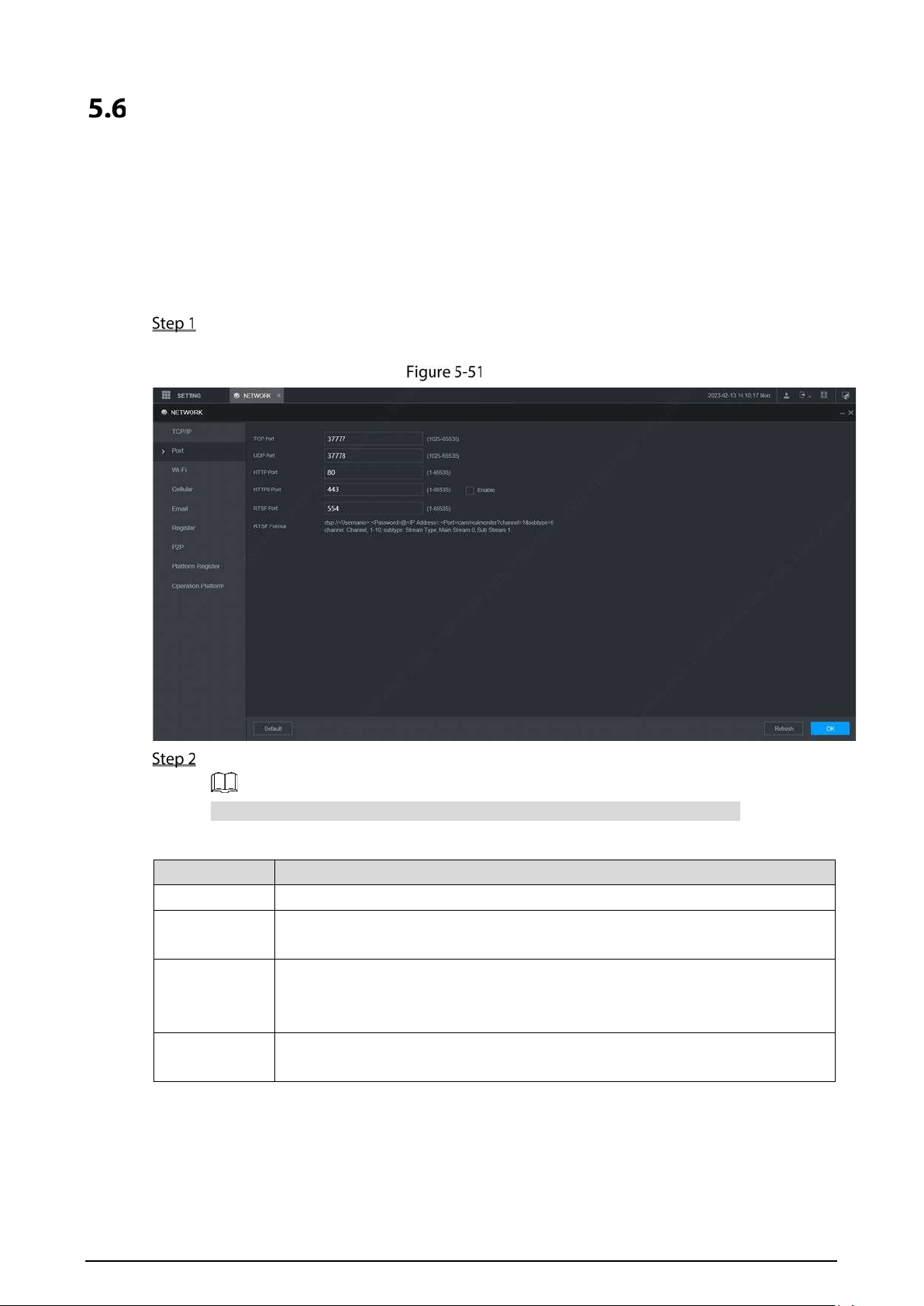
105
Configuring Network Parameters
You can set the network parameters of the device as needed, including port, Wi-Fi parameters,
cellular parameters, email, register, P2P and operation platform.
5.6.1 Port
You can configure the maximum number of ports and their respective values.
Select SETTING > NETWORK > Port.
The Port interface is displayed.
Port
Configure the ports of the device.
The revised settings take effect after device restart. Proceed with caution.
Table 5-17 Port parameters
Parameter Description
TCP port Transmission Control Protocol port. The value is 37777 by default.
UDP port
User Datagram Protocol port. The value is 37778 by default. You can enter the
value as needed.
HTTP port
Hyper Text Transfer Protocol port. The value is 80 by default. You can enter other
values as needed, in which case, add the new value after the address when
logging in to the device in the browser.
HTTPS port
Hyper Text Transfer Protocol over Secure Socket Layer port. Select Enable, and
then enter the value as needed. The value is 443 by default.

106
RTSP port
Real Time Streaming Protocol port. Keep the default value 554 if it is
displayed. If you use Apple browser, QuickTime or VLC to play the
real-time monitoring screen, the following formats can be used: This
function is also available for Blackberry phones.
When
the URL format requiring RTSP, you need to specify channel
number and code-stream type in the URL, and also user name and
password if needed.
When playing live view with Blackberry smart phone, you need to turn
off the audio, and then set the compression to H.264B and resolution to
CIF.
URL format:
rtsp://<User Name>:<Password>@<IP
Address>:<Port>/cam/realmonitor?channel=1&subtype=0
User name, such as admin.
Password, such as admin_123.
IP address, such as 192.168.1.16.
Port: The default setting is 554. If the default setting is displayed, you
do not need to configure this parameter.
Channel: channel number, starting from 1. For example, if it is channel
2, enter channel=2.
Subtype: code-stream type. The main stream is 0 (subtype=0); the sub
stream is 1 (subtype=1).
For example, if you request the sub stream of channel 2 from a certain device,
the URL should be:
rtsp://admin:admin_123@192.168.1.16:554/cam/realmonitor?channel=2&subty
pe=1
If certification is not required, there's no need to specify the user name and
password. Use the following format:
rtsp:// <IP Address>:<Port>/cam/realmonitor?channel=1&subtype=0
NTP port The port that automatically syncs time with the NTP server is 123 by default.
Click OK.
5.6.2 Wireless Network
You can connect the device to a network through Wi-Fi. Make sure the device can
communicate with other devices in the group network. The device itself can also act as a hot
spot to share flows with other terminals.
If both 3G/4G and Wi-Fi are available, the device connects to Wi-Fi and disconnects from
3G/4G.
5.6.2.1 Wi-Fi Network
You can connect the device to a network through Wi-Fi. Then connect the PC to the same
network. You can log in to the web interface by PC to operate the device.

107
This function is only supported by the device with a Wi-Fi module. The actual situation shall
prevail.
Preparation
Make sure that the device is connected to a Wi-Fi module.
Procedure
Select SETTING > NETWORK > Wi-Fi.
The Wi-Fi interface is displayed.
Select Wifi as the working mode.
The Wi-Fi interface is displayed.
Wi-Fi
Connect to Wi-Fi.
Auto search
1. Click Search SSID.
In the SSID list, all available wireless networks are listed, including the
information such as network name, security type, encryption type, and signal
intensity.
2. Double-click the Wi-Fi you want to connect to, enter the password, and then
click OK.
Add Wi-Fi manually.
1. Click Static Setting.
The Wi-Fi interface is displayed.
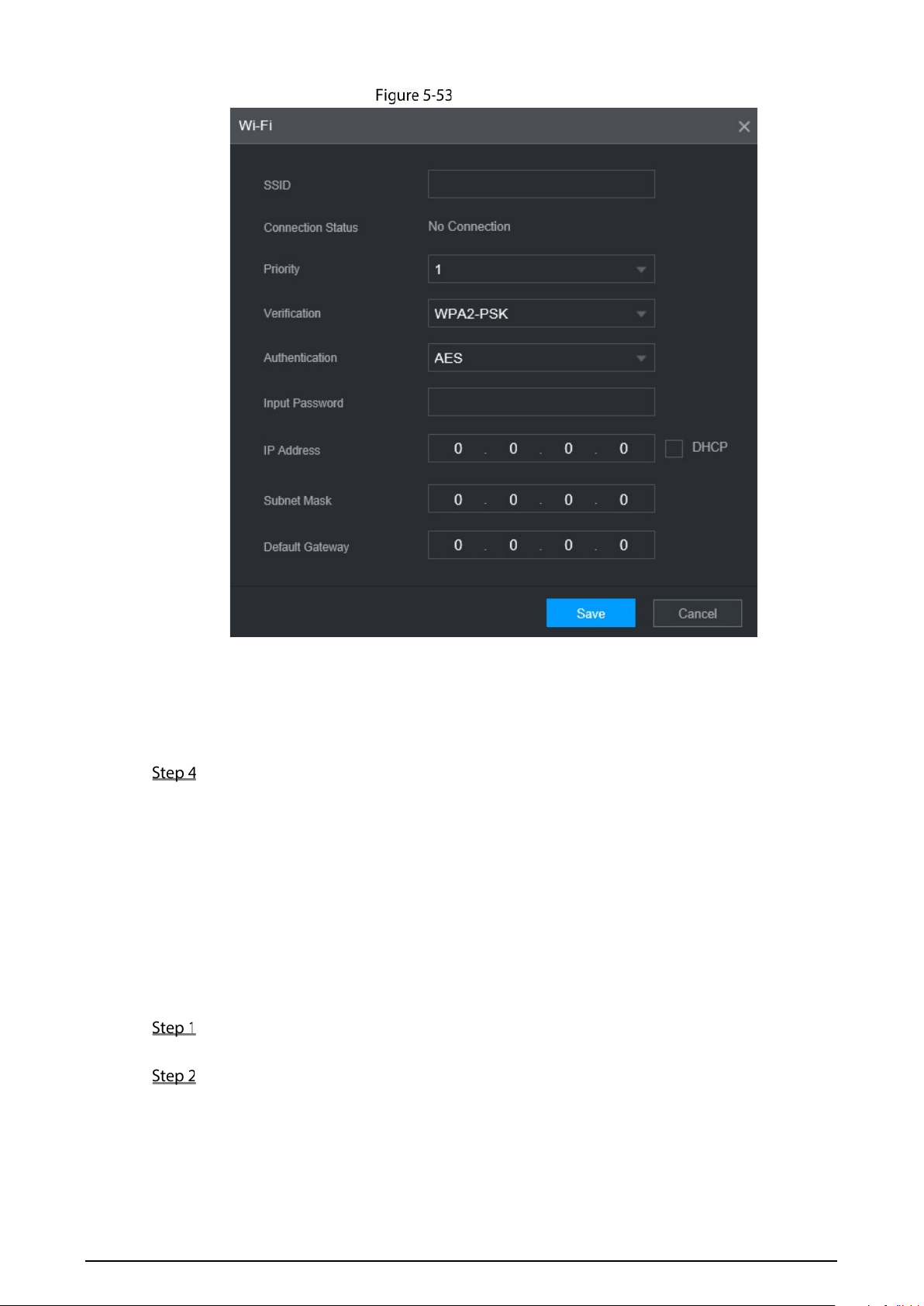
108
Wi-Fi settings
2. Enter SSID and password, select priority and verification type, set IP address,
subnet mask, and gateway.
If you select DHCP check box, after successful connection, the system
automatically obtains the IP address, subnet mask, and gateway.
3. Click OK.
Click OK.
Click Refresh to refresh the connection status.
After successful connection, you can view the current hot spot, IP address, subnet mask, and
gateway in Wi-Fi Working Info.
5.6.2.2 Wi-Fi Hot Spot
The device can work as a hot spot to share the network connection to other terminals. The
terminals connected to the hot spot can log in to the device through host IP address
(192.168.0.108). After login, you can view videos on the device.
Select SETTING > NETWORK > Wi-Fi.
The Wi-Fi interface is displayed.
Select Ap as the working mode.
The Ap interface is displayed.
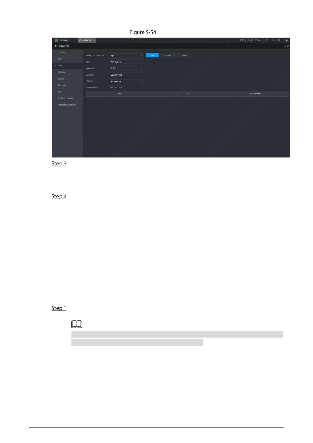
109
Ap settings
Enter SSID, select work band and verification type, and then enter the password.
The work band can only be 2.4G.
Select the check box behind Password, and the password will be visible. The
default password is 12345678.
Click OK.
5.6.3 Cellular
Prerequisites
Make sure that the device is equipped with cellular module and inserted with SIM card from
corresponding communication operators.
The dial number, user name, and password have been obtained from corresponding
communication operators.
Procedure
Select SETTING > Network > Cellular.
The Cellular interface is displayed. See Table 5-19.
After Cellular module is connected, the module information and wireless signal are
displayed; if not, click Search to search for wireless signal.
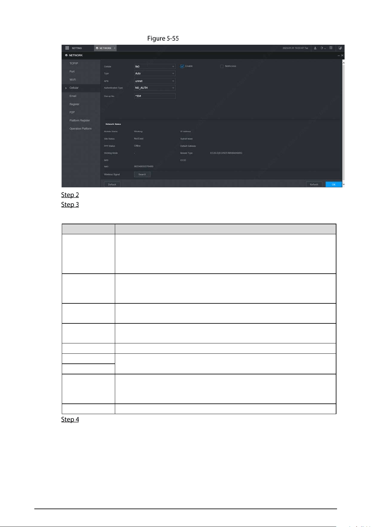
110
Cellular settings
Select Ite0 and Enable to enable the network. This function is enabled by default.
Configure parameters. For details, see Table 5-18.
Table 5-18 Cellular setting parameters description
Parameter Description
NetAccess
When the Device is accessed to private network, select the NetAccess check
box, enter APN name and select authentication mode. If PAP or CHAP is
selected for authentication mode, enter user name and password, then the
device is automatically accessed to private network.
Type
When enabled, the network type is displayed, which is used to distinguish
between the 3G/4G modules of different communication operators, such as
TD-LTE.
APN
Displays access point of Communication Operator.
To manually set up APN, select Customized.
Authentication
Type
Includes PAP, CHAP, and NO_AUTH protocols. The system automatically
recognizes and displays the enabled protocol.
Dial-up No Enter the dial number provided from the Communication Operator.
User Name
This parameter needs to be set up when AUTH is set to PAP o r C HA P.
The system automatically recognizes the user name and password.
Password
Network Status
After successful dial-up, all relevant information is displayed without any setup
needed. Such information includes module status, SIM status, PPP status,
working mode, IMSI, IMEI, IP address, subnet mask, gateway, and module type.
Wireless Signal
Click Search to search for wireless signals.
Click OK.
After access is succeeded, the obtained IP address is displayed.
5.6.4 Email
You can configure the email settings to enable the system to send the email as a notification when
there is an alarm event occurs, such as video detection and system events.
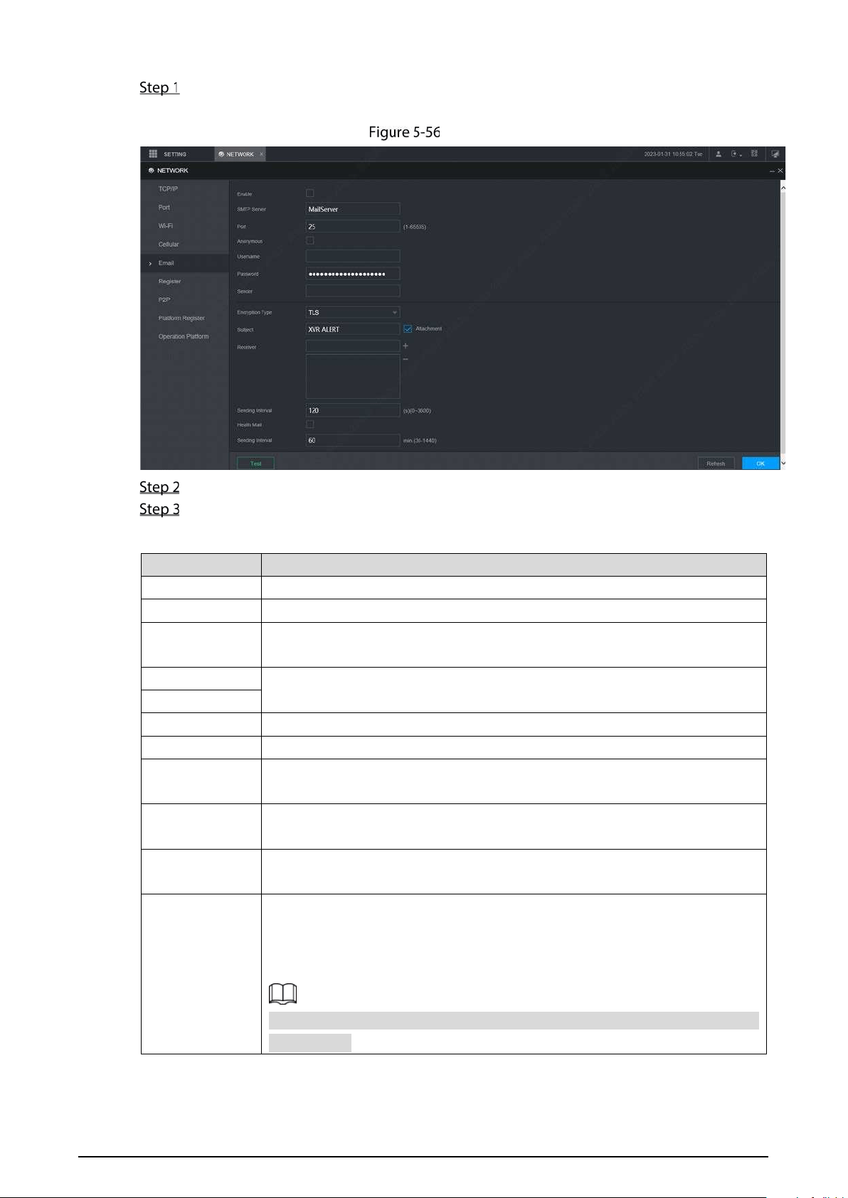
111
Select SETTING > Network > Email.
The Email interface is displayed. See Figure 5-56.
Email
Select Enable to enable email function.
Configure parameters. For details, see Table 5-19.
Table 5-19 Email parameters description
Parameter Description
SMTP server Configure the address of Simple Mail Transfer Protocol.
Port Enter the port value of SMTP server.
Anonymous
If Anonymous is selected, the sender information is not displayed when
sending an email.
User Name
Enter the user name and password of SMTP server.
Password
Sender Email address of sender.
Encryption Type In the Encrypt list, select an encryption type from None, SSL, and TLS.
Subject
You can enter no more than 63 characters in Chinese, English, and Arabic
numerals.
Attachment
If Attachment is enabled, when an alarm takes place, the system can send
alarm linked snapshots.
Receiver
Receiver’s Email address. You can enter up to three email addresses separated
by colons.
Sending Interval
This is the interval that the system sends an email for the same type of alarm
event, which means, the system does not send an email upon any alarm event.
The interval ranges from 0 through 3600 seconds. 0 means that there is no
interval.
This setting helps to avoid the large amount of emails caused by frequent
alarm events.
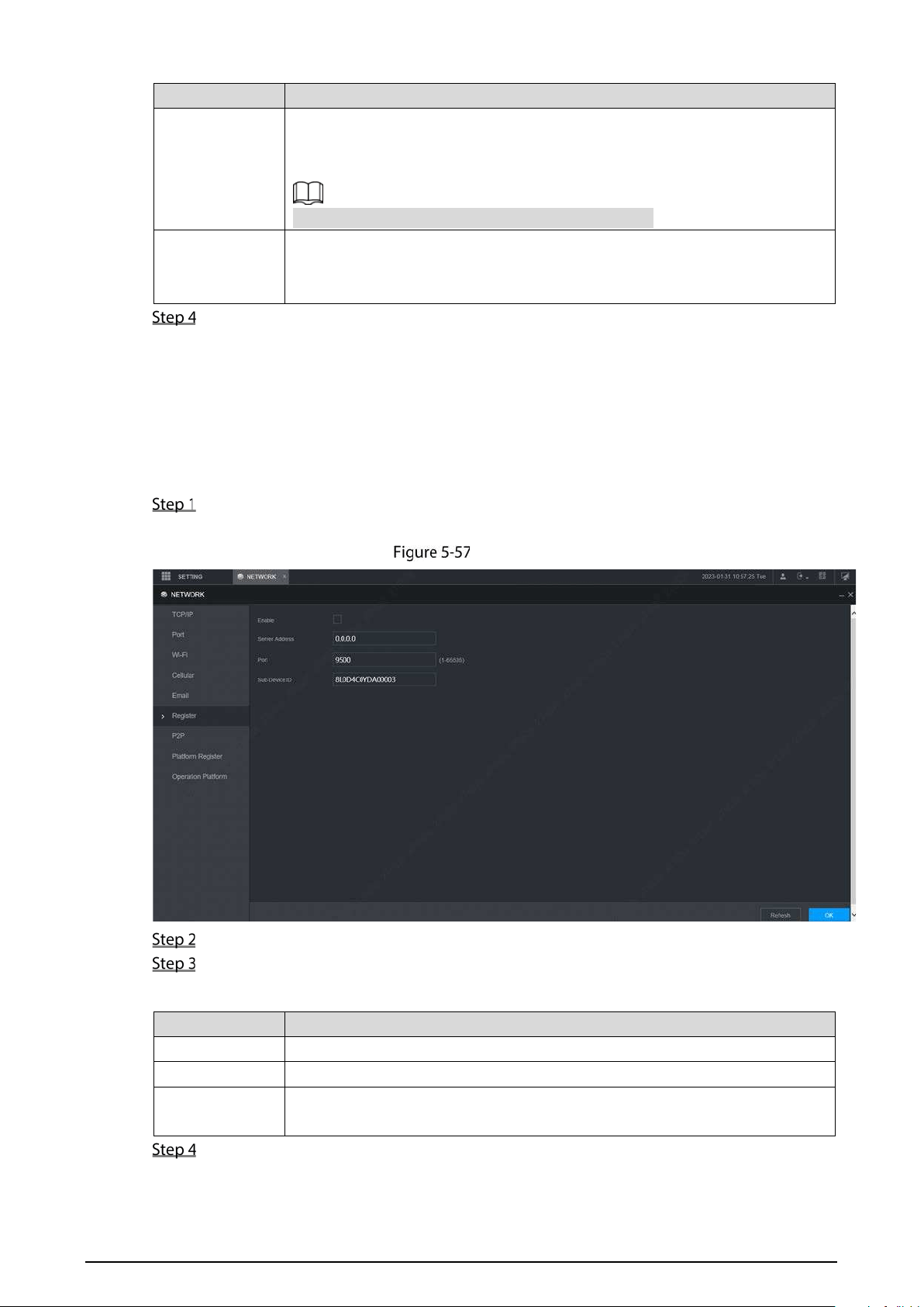
112
Parameter Description
Health Mail
The system can send a test email to check the connection.
Select the Health Mail check box, and then enter the interval. The system can
send a test email to check the connection after the specified interval.
The interval ranges from 30 minutes to 1440 minutes.
Test
Click Test to test if emails can be sent out and received as intended. If the
configuration is correct, the receiver’s email account will receive the test email.
Before testing email, click OK to save the email configuration.
Click OK.
5.6.5 Register
After successfully auto registered, when the device is connected into the Internet, it will report the
current location to the specified server to make it easier for the client software to access to the
device, and to view and monitor it.
Select SETTING > Network > Register.
The Register interface is displayed. See Figure 5-57.
Register
Select the Enable check box. (Selected by default)
Configure parameters. For details, see Table 5-20.
Table 5-20 Register Parameters
Parameter Description
Server Address Enter the IP address or domain name of the server to register.
Port The port for auto-registration.
Sub-device ID
Unique ID for identifying the device. When different devices register to the
same server, the sub-device IDs should be different.
Click OK.
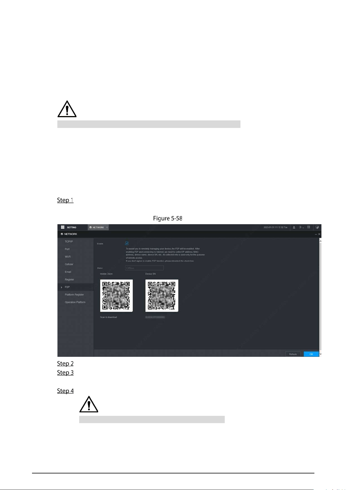
113
5.6.6 P2P
P2P is a private network penetration technology. With this technology, you do not need to apply for
dynamic domain name, set port mapping, or deploy transit server. You can add devices for
management by either of the following two ways.
Scan the QR code on the interface to download the app, and register an account.
Log in www.gotop2p.com platform to register, and then add devices by device serial number.
Before using P2P, make sure that the device is connected to the Internet.
Prerequisites
The device had been connected to the Internet.
App has been downloaded and installed on the mobile phone.
Procedure
Select SETTING > Network > P2P.
The P2P interface is displayed, see Figure 5-58.
P2P
Select Enable to enable P2P.
Click OK.
The P2P registration is successful when the Status shows Online.
Use Mobile Client to scan the QR code under Device SN to add the device to Mobile Client.
Please scan the QR code on the actual interface of device.
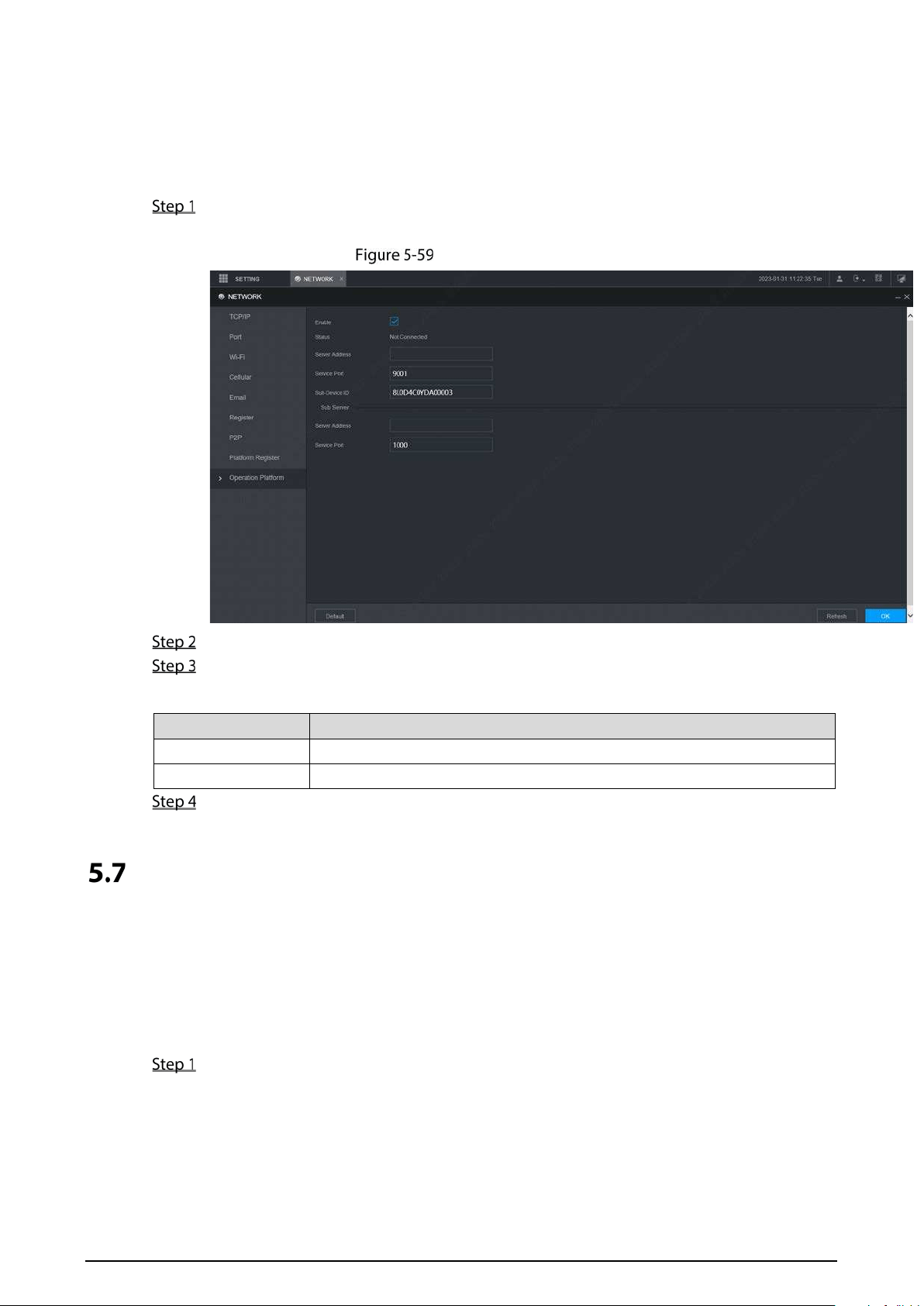
114
5.6.7 Operation Platform
By connecting to the operation platform, you can modify the configuration information of the
recorder, collect the print information and GPS raw data, and upgrade remotely.
Select SETTING > NETWOTRK > Operation Platform.
The Operation Platform interface is displayed. See Figure 5-59.
Operation Platform
Select Enable.
Configure parameters. For details, see Table 5-21.
Table 5-21 Operation platform parameters
Parameter Description
Server IP Address Enter the IP address or domain name of the server to register.
Server Port Enter the port of the server to register.
Click OK.
Managing Storage Device
You can configure storage, basic information, manage HDD, and review HDD information.
5.7.1 Basic
On the Local interface, you can set up the strategy when the Disk is full and recording mode.
In the main menu, select Setting > Storage > Basic.
The Basic interface is displayed. See Figure 5-60.
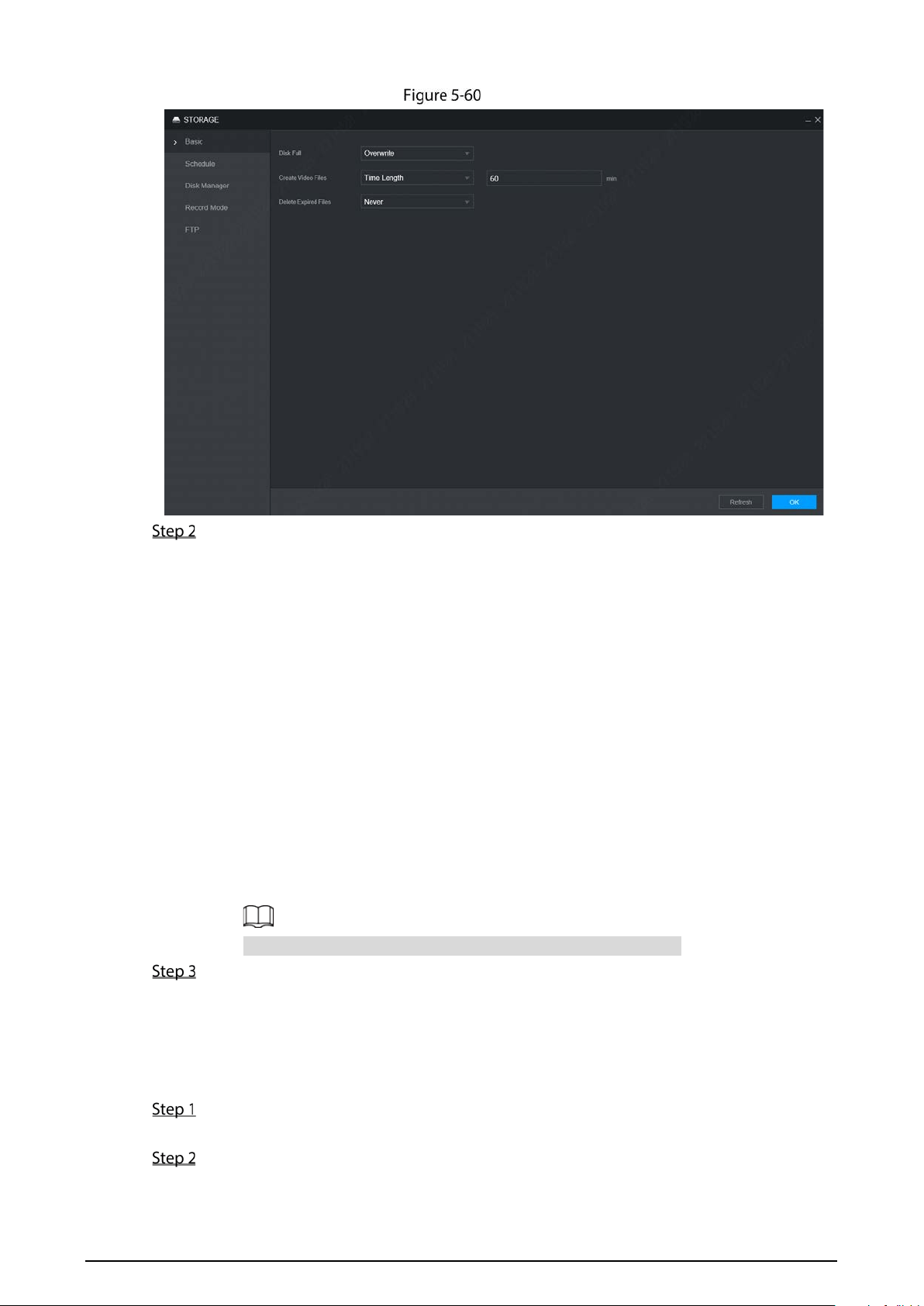
115
Basic
Configure basic information.
Select the processing strategy of stopping recording and overwriting earlier recordings
when TF Card is full.
◇ Stop: The system stops recording when the disk is full.
◇ Overwrite: The system overwrites the oldest files and keeps recording when the
disk is full.
Set up the time length or file size for video packaging.
Select the required packaging manner from the Create Video Files drop-down list.
Including Time Length and File Size.
◇ Set the length of time for each video file. The default value is 60 minutes, and the
range is 1 minute –120 minutes.
◇ Set the size of file for each video file. The default value is 1024M, and the range is
128M –2048M.
Set the strategy of deleting old files automatically.
You can enable this function to delete recorded videos or images saved in TF card or
FTP server regularly according to the time gap you have set.
After setting file auto deletion, deleted files cannot be recovered.
Click OK.
5.7.2 Disk Manager
Set the read and write properties of the TF card and view the capacity information of the HDD.
Select SETTING > Storage > Disk Manager.
The Disk Manager interface is displayed. See Figure 5-61.
Set the read and write properties of the TF card. You can set the TF card as the Read/Write
disk, Read-Only disk or Redundancy disk under the Properties column.
Read/Write: You can read data from TF card and save data in TF card.
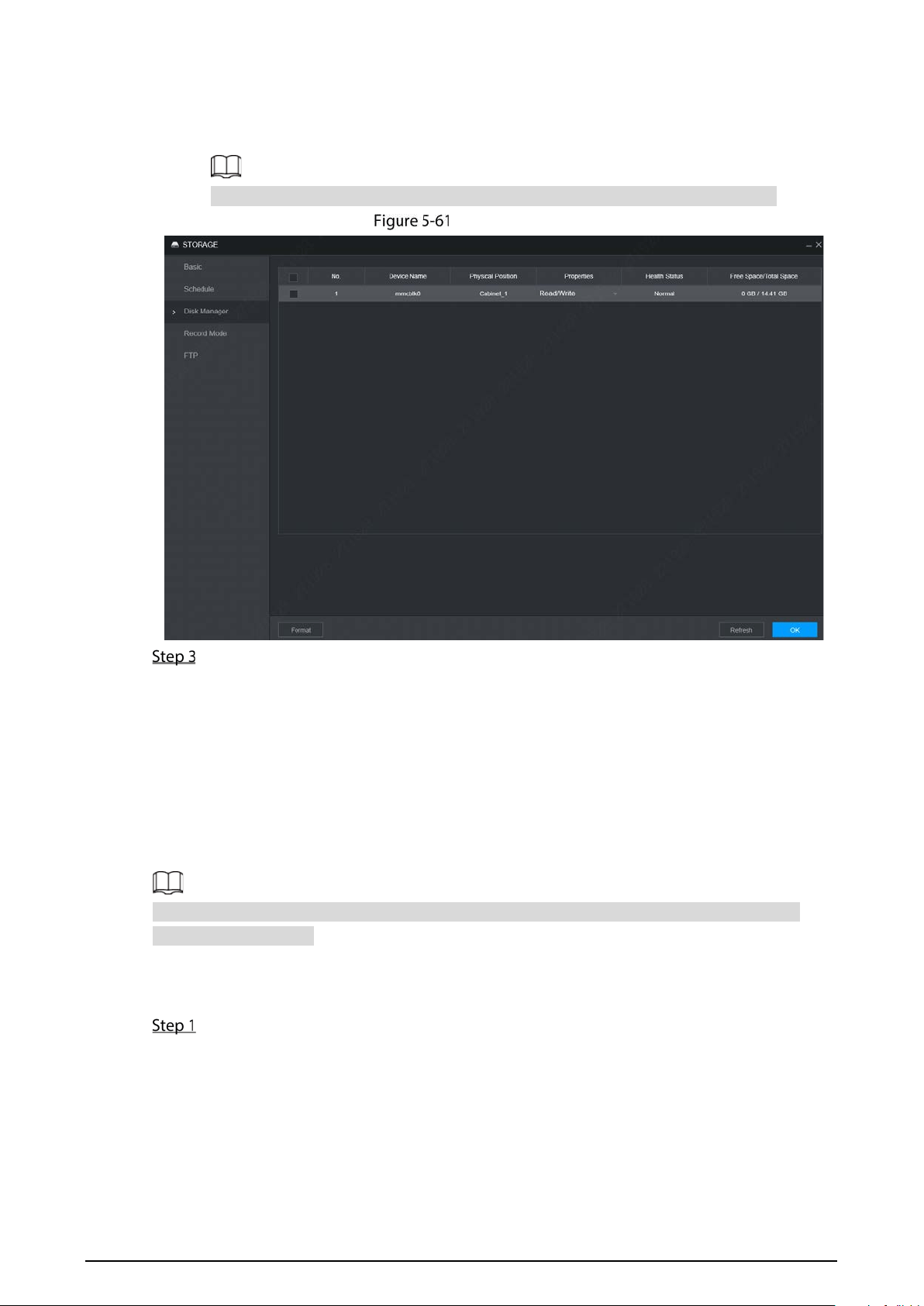
116
Read-Only: You can only read data from TF card if set to read-only disk.
Redundancy: If the device is connected to two or more TF cards, one of the TF cards can
be set as the redundancy one for recording backup.
Select TF card and click Format to clear all data in the TF card. Proceed with caution.
Disk Manager
Click OK.
5.7.3 FTP
Configure FTP server, and then you can save videos and snapshots to the FTP server.
Prerequisites
You have deployed a FTP server, and created a user with the read & write permission.
The created FTP user should have write permission; otherwise the upload of videos, audios, and
snapshots will be failed.
Procedure
Select SETTING > Storage > FTP.
The FTP interface is displayed, see Figure 5-62.
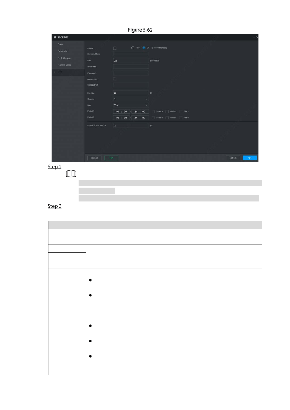
117
FTP
Select Enable to enable FTP upload and select FTP type.
You select FTP or SFPT from the drop-down list. SFTP is recommended to enhance
network security.
When FTP is selected, the system gives a risk prompt. Select OK or Cancel as needed.
Configure parameters. For details, see Table 5-22.
Table 5-22 FTP parameter description
Parameter Description
Server Address The IP address of the host PC that is installed with the FTP/SFTP server.
Port By default, SFTP port is 22 and FTP port is 21.
User Name
The user name and password used to access the server.
Password
Anonymous
Select Anonymous if you want to log in to the server anonymously.
Storage Path
Create folder on FTP server.
If you do not enter the name of remote directory, the system automatically
creates the folders according to the IP, time, and channel.
If you enter a name for the remote directory, the system creates a folder
with the entered name under the FTP/SFTP root directory first, and then
automatically creates folders based on IP, time, and channel.
File Size
Enter the size of the uploaded recorded video.
If the entered size is less than the recorded video size, only a section of the
recorded video can be uploaded.
If the entered size is more than the recorded video size, the whole recorded
video can be uploaded.
If the entered size is 0, the whole recorded video will be uploaded.
Choose
channel
Select the channel that you want to apply the FTP settings.

118
Parameter Description
Weekday
Select the week day and set the time period that you want to upload the
recorded files. You can set two periods for each week.
Select the record type (Alarm, MD, and General) that you want to upload. After
selecting the corresponding recording type next to the corresponding period,
the selected recording type will be uploaded during the configured period.
Period
Picture Upload
Interval
When the Snapshot Type is Schedule
, the upload method should be
determined based on the image upload interval and snapshot interval.
If this interval is longer than snapshot interval, the system uploads the
most recent snapshot. For example, if the interval is 5 seconds and
snapshot interval is 2 seconds, the system sends an upload command
to upload the next snapshot every 5 seconds.
If this interval is shorter than snapshot interval, the system uploads the
snapshot per the snapshot interval. For example, if the interval is 5
seconds and snapshot interval is 10 seconds, the system uploads the
snapshot every 10 seconds.
When the Snapshot Type is Event, the system uploads the snapshot as per
the snapshot interval.
You can change the Interval and Type. For details, see “5.5.2.2Snapshot”.
Click Test to test if the FTP/SFTP server is successfully configured.
The system pops up a message to indicate success or failure.
If failed, please check the network connection or configurations.
Click OK.
Configuring System
You can configure system information, including serial port, security, and vehicle information.
5.8.1 Configuring Serial Port Parameters
You can configure the RS-232 serial port parameters such as baud rate, data bit, stop bit, and parity.
Select SETTING > System > Serial Port.
The Serial Port interface is displayed. See Figure 5-63.

119
Serial Port
Configure parameters. For details, see Table 5-23.
Table 5-23 Serial port setting parameters description
Parameter Description
Function
Select the corresponding protocol.
Console: Upgrades programs and debug by suing the serial interface and mini
terminal software.
GPS:Used to transmit real-time GPS data.
Baudrate
The times of signal changes on the transmission line in time unit.
The default baud rate is 115200 for a console.
The default baud rate is 9600 for a transparent serial port.
Data Bit
Select a data bit. The options include 5,6, 7, and 8.
Stop Bit
Select a stop bit. The options includes 1, 1.5, and 2.
Parity
Select a parity mode from None, Odd, Even, Mark, and Null. The default is None.
Click OK.
5.8.2 Managing Security
It is to set security strategy to guarantee device network and data safety. It includes setting host IP
access right and enabling system service, etc.
5.8.2.1 System Service
The corresponding service can only be used after the system service is turned on.
Select SETTING > System > Security > System Service.
The System Service interface is displayed. See Figure 5-64.

120
System service
Select whether to enable mobile phone push, CGI, SSH, or audio/video transmission
encryption as needed.
App can receive alarm push only when the mobile phone push is enabled and the app
has subscribed alarm.
After enabling CGI, other platform can connect to this device via the CGI protocol.
When audio/video transmission encryption is enabled, audio/video transmission will
be encrypted. Related devices or software shall support video decryption.
Click OK.
5.8.3 Configuring Vehicle Info
You can set the vehicle speed ratio and position report.
5.8.3.1 Configuring Speed
Select SETTING > System > Vehicle > Speed.
The Speed interface is displayed. See Figure 5-65.
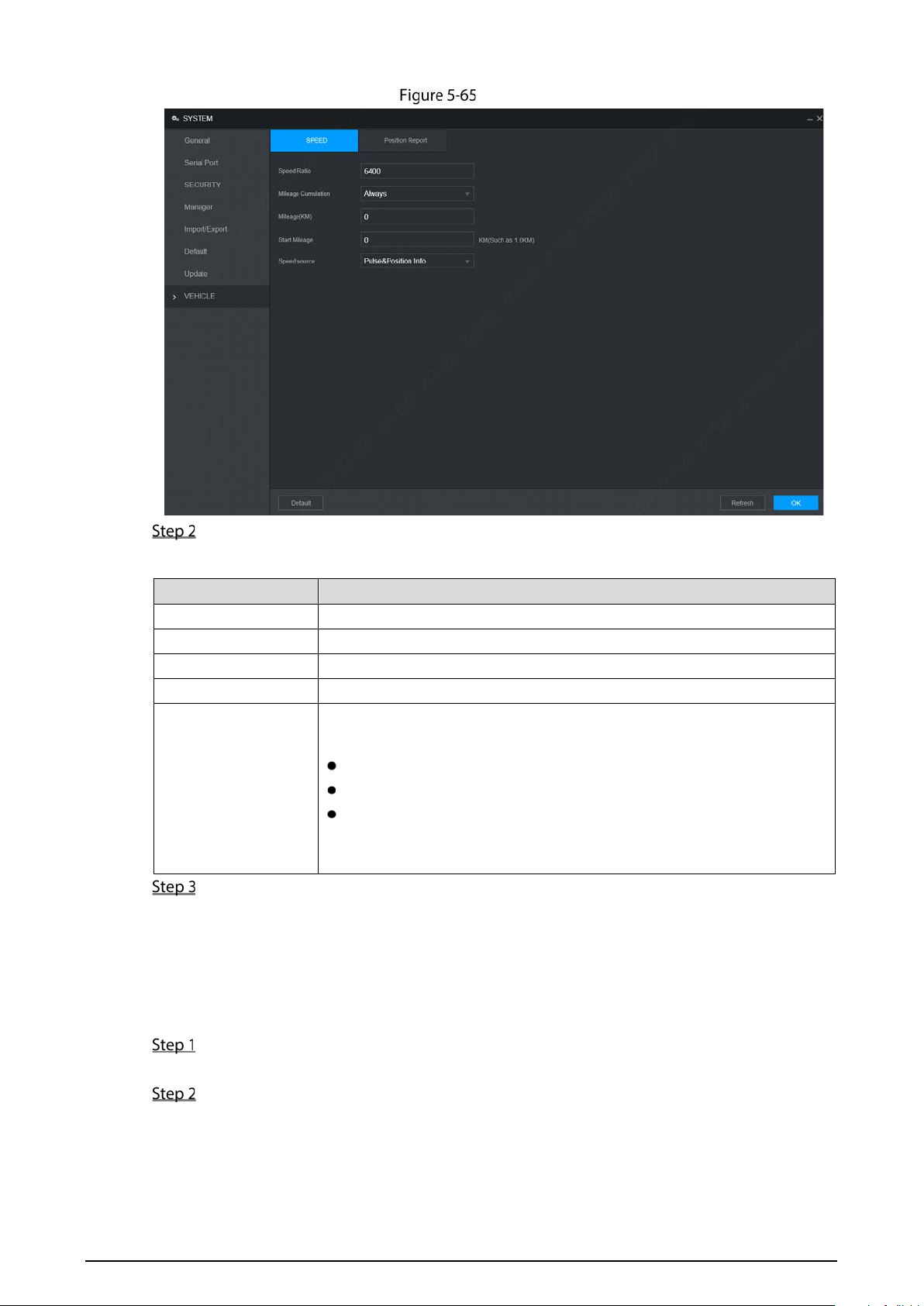
121
Speed
Configure parameters. For details, see Table 5-24.
Table 5-24 Speed parameters description
Parameter Description
Speed Ratio The parameter for converting speed.
Mileage Cumulation Select the vehicle mileage cumulation mode.
Mileage Displays the total mileage.
Start Mileage Enter the initial mileage of the vehicle.
Speed source
Select where the speed is obtained, including Pulse, Position Info, and
Pulse&Position Info.
Pulse: Get the speed information from vehicle pulse system.
Position Info: Get the speed information from positioning system.
Pulse&Position Info: Gets the speed information from both the pulse
system and positioning system. Information from the pulse system is
used first.
Click OK.
5.8.3.2 Configuring Position Report
You can configure the position report strategy to be device auto report or report per platform
schedule.
Select SETTING > System > Vehicle > Position Report.
The Position Report interface is displayed. See Figure 5-66.
Configure the report strategy.
Device auto report.
4. In the Report Strategy list, select Device Auto.
The Device Auto setting interface is displayed. See Figure 5-66.
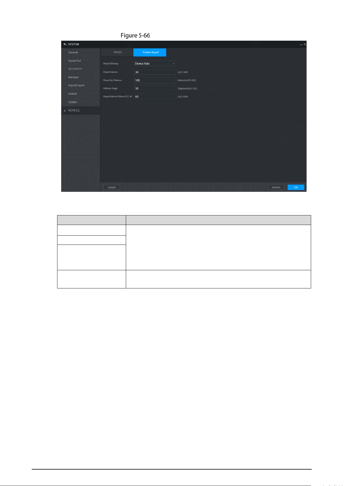
122
Position report (device auto)
5. Configure parameters. For details, see Table 5-25.
Table 5-25 Device auto report parameters description
Parameter Description
Report Interval
When the vehicle ACC status is on, the system report the position to
platform according to the configured report interval, report distance,
and inflexion angle.
The system reports vehicle position to platform only if one of
conditions is satisfied.
Report by Distance
Inflexion Angle
Report Interval When
ACC off
When the vehicle ACC status is off, the system report the position to
platform according to the configured report interval.
Platform schedule.
In the Report Strategy list, select Platform Schedule. The Platform Schedule setting
interface is displayed. See Figure 5-67.
The platform obtains the device position by the configured schedule. The schedule is
configured at the platform. See the user's manual for the platform.

123
Position report (platform schedule)
Click OK.
Managing User Account
You can add, modify and delete user accounts and groups, and configure security questions for
admin account.
The Default User and Authority
The default user account is admin.
The admin account is defined as the highly privileged user by default.
To manage user accounts easily, when defining the user account authority, it is recommended
to give lower authority to common user accounts than advanced user account.
About User and User Group
You can manage the account by user and user group, and the name cannot be repeated.
You can set maximum 64 users and 20 groups.
The default group name by “User” and “Admin” cannot be deleted.
Select the authorities to the user of a group. However, the authorities of the admin account
cannot be specified at your will.
Every user must belong to only one group. When selecting a group for a user, permissions of the
user can only be a subset of group permissions and cannot exceed permission attributes of the
group.
Both the user name and group name support 1–31 characters and can only consist of letter,
number, underline (_), and hyphen (-).

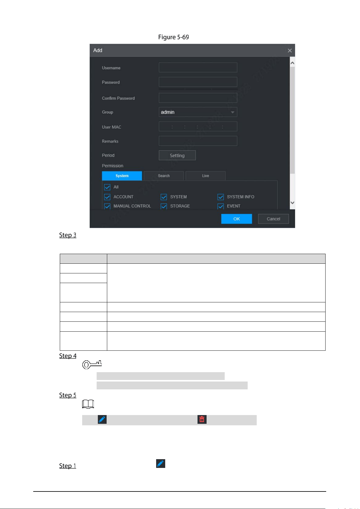
125
Add
Configure parameters. For details, see Table 5-26.
Table 5-26 Parameters description for adding user
Parameter Description
User Name
Enter the user name and password, and confirm the password.
Password
Confirm
Password
Group Select the group that the users belong to.
User MAC Enter user MAC address that is allowed to login the device.
Remarks Enter a description of the user.
Period
Click Setting to set a valid period. The user is only allowed to log in to the device
in the set period.
Click System, Search, or Live to set up user permissions.
Select All to select all authorities in the category.
The authorities of the admin account cannot be changed.
Click OK.
Click to modify user information; click to delete the user.
Changing Password
On the User interface, click .
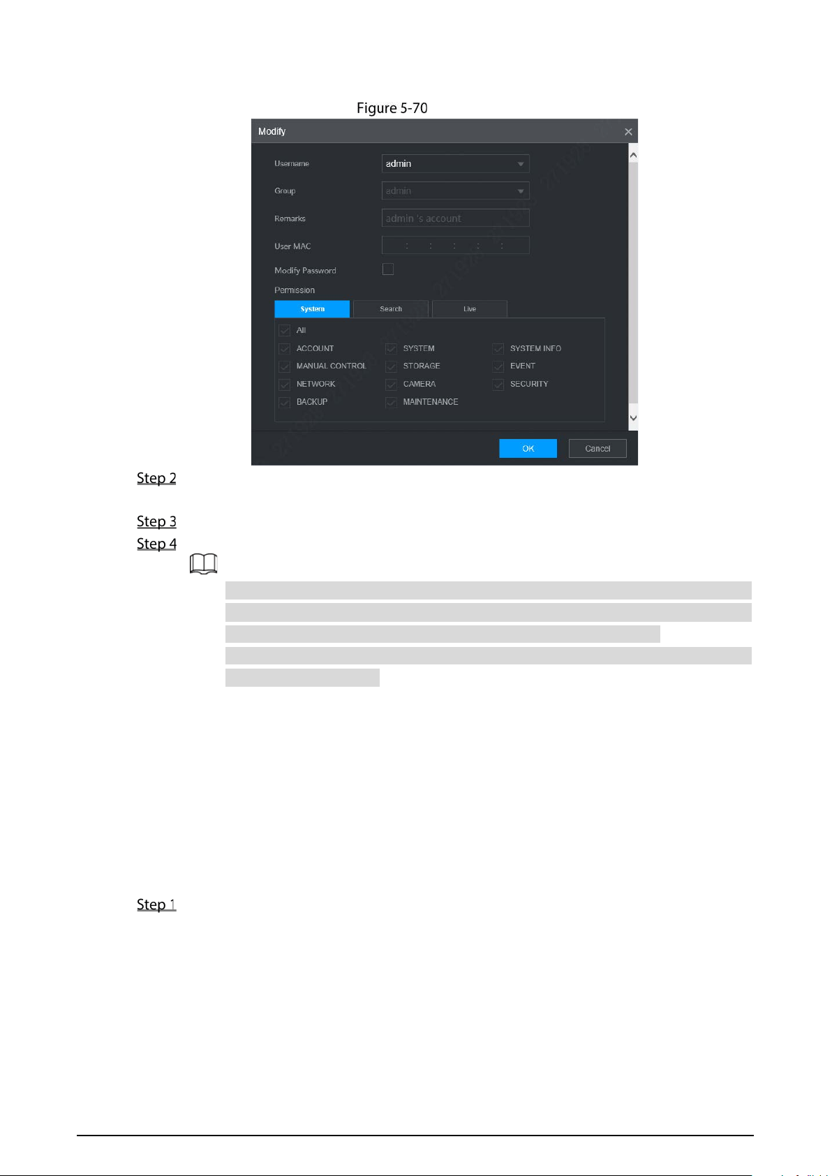
126
The Modify interface is displayed. See Figure 5-70.
Modify
Select the Modify Password check box, and then enter old password, new password, and
confirm password in the corresponding box.
Select the authority, including system, search, and live authorities.
Click OK.
The new password can be set from 8 characters through 32 characters and contains at
least two types from number, letter and special characters (excluding ' " 、; : &). Please
enter a strong password according to the password strength indication.
A user authorized to manage user accounts can modify its own password and the
passwords of other users.
5.9.2 Managing ONVIF User
When the remote device is connecting with the device through ONVIF protocol, please use the
verified ONVIF account. Note System adopts three ONVIF user groups (admin, user and operator).
You cannot add ONVIF user group manually.
Adding a user
Select SETTING > Account > Account > ONVIF User.
The ONVIF User interface is displayed, see Figure 5-71.
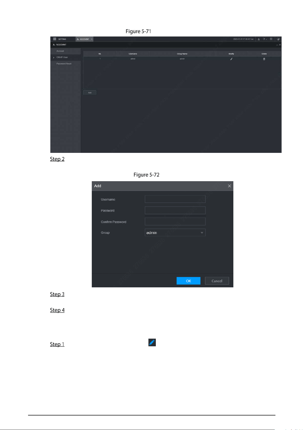
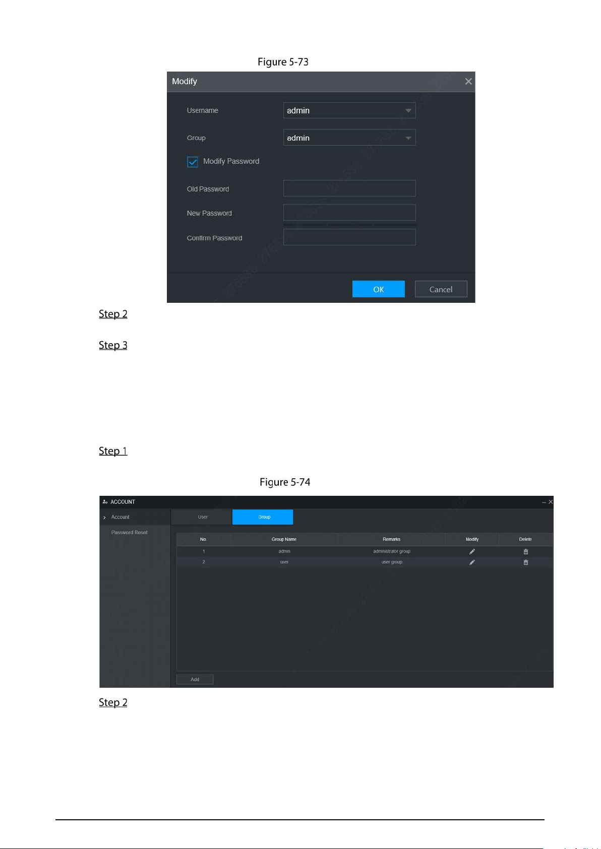
128
Modify
Select the Modify Password check box, and then enter old password, new password, and
confirm password in the corresponding box.
Click OK.
5.9.3 Managing Group
You can perform the operations to manage the group account, such as adding a group, deleting a
group, and modifying a group.
Select SETTING > Account > Account > Group.
The Group interface is displayed, see Figure 5-74.
Group
Click Add.
The Add interface is displayed. See Figure 5-75.
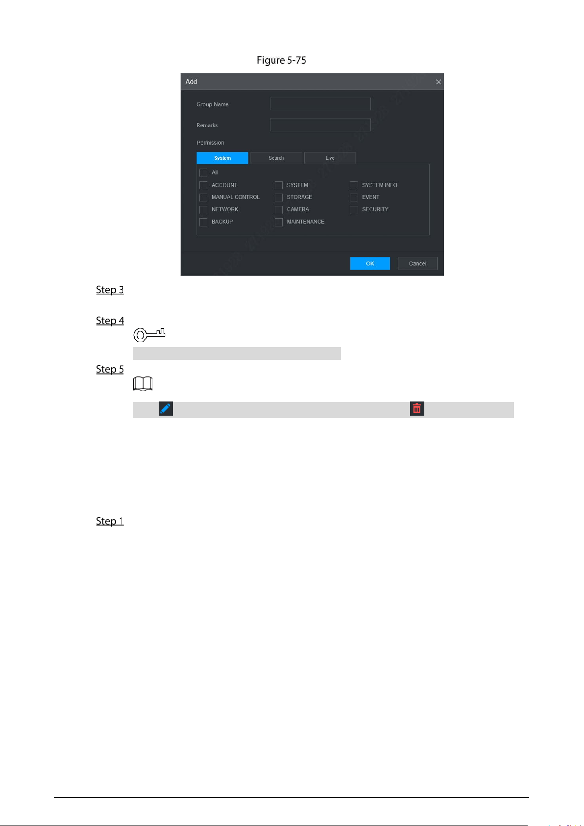
129
Add
Set group name and remarks.
A group name consists of letters, numbers, and special characters (including "_", "@", ".").
Select the authority, including system, search, and live authorities.
Select All to select all authorities in the category.
Click OK.
Click to modify the corresponding group information; click to delete the group.
5.9.4 Resetting Password
You can reset the password through the reserved phone number when you forget the login
password of admin.
Open a browser and login the WEB interface of device.
The Login interface is displayed. See Figure 5-76.
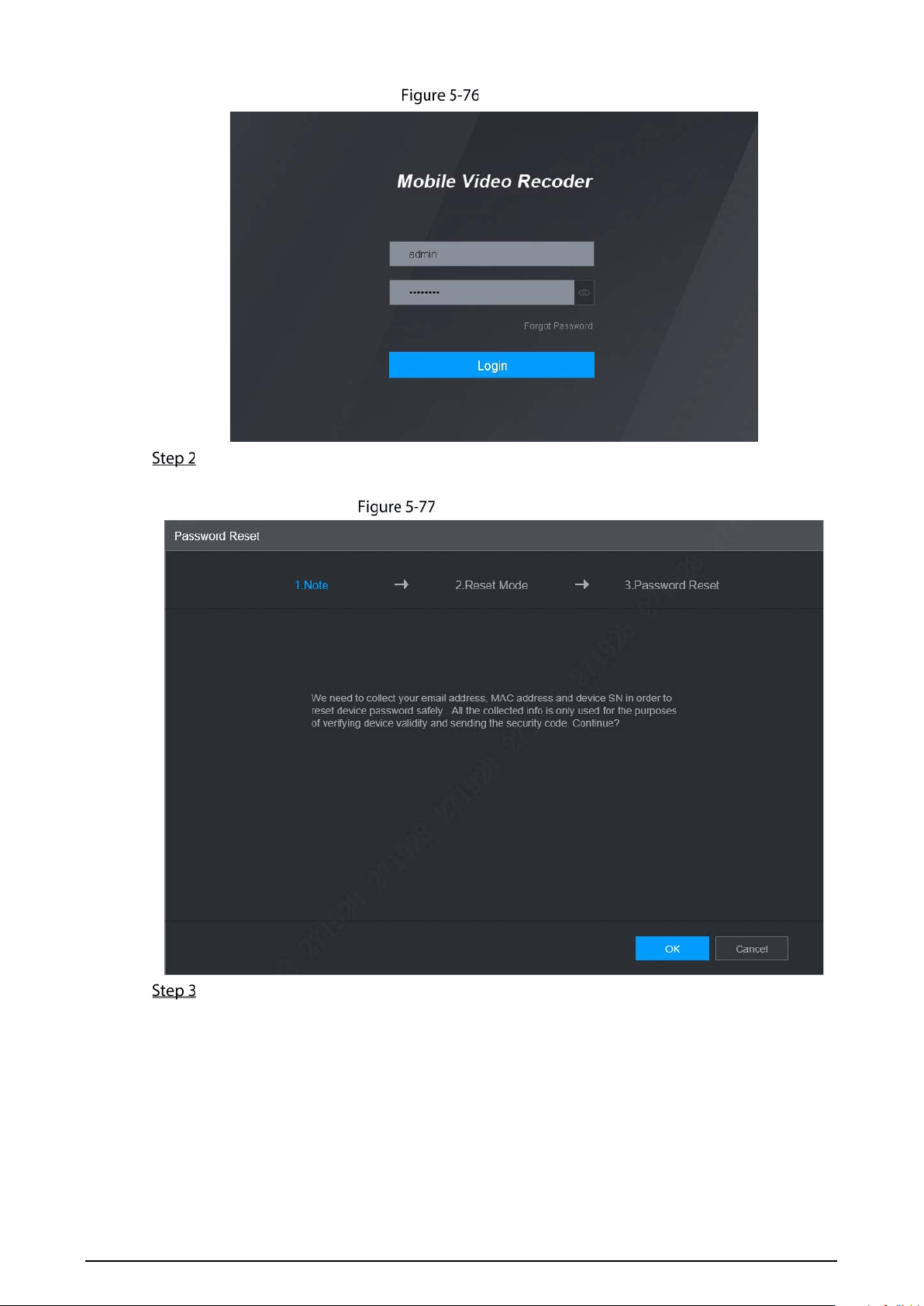
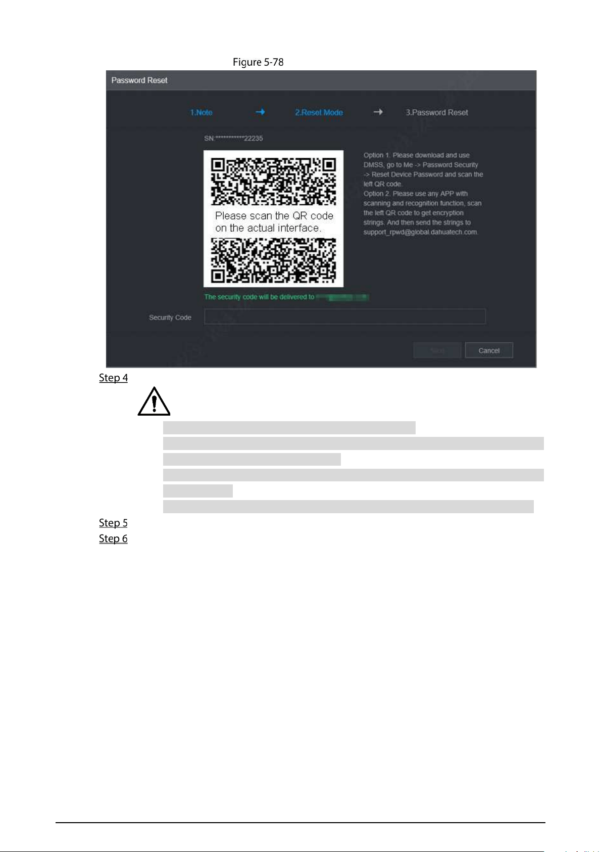
131
Password Reset (2)
Follow the onscreen instructions to scan the QR code and get the security code.
Please scan the QR code on the actual interface of device.
At most two security codes will be generated by scanning the same QR code. To get
more security code, refresh the QR code.
Please use the security code within 24 hours after you receive it. Otherwise, it will
become invalid.
Wrong security code entered for up to five times will cause account locked for 5 min.
In the Security Code box, enter the security code received in your provided mailbox.
Click Next.
The new password setting interface is displayed. See Figure 5-79.
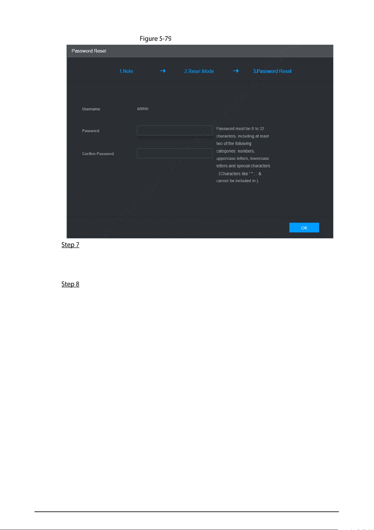
132
New password setting
Reset and confirm the password.
The new password can be set from 8 through 32 non-empty characters and contains at least
two types from number, letter and special characters (excluding “'”, “"”, “;”, “:” and “&”). Please
enter a strong password according to the password strength indication.
Click OK.
The system prompts successful operation and restarts. You can use the new password to log
in to the device.
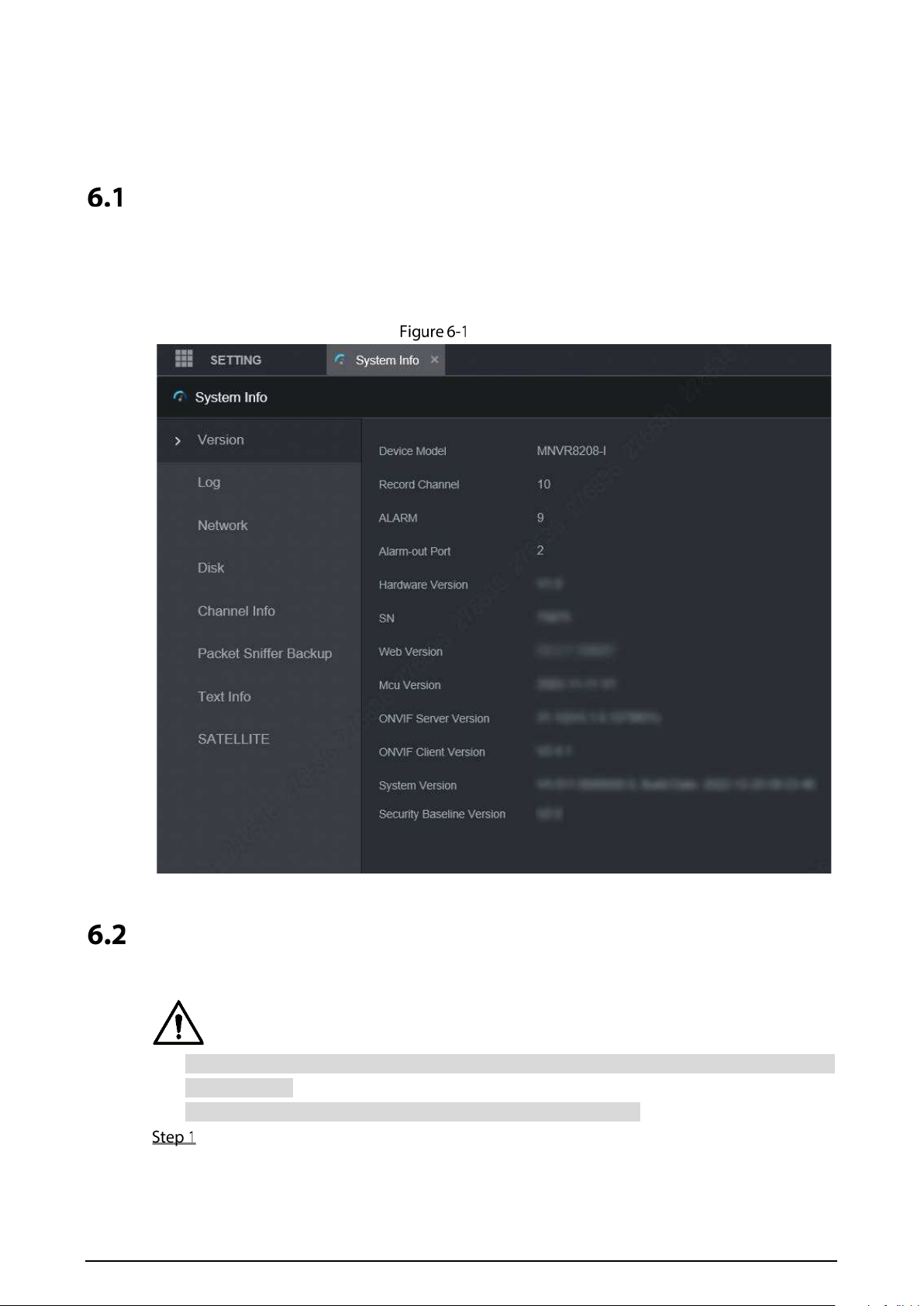
133
6 Update
System Version
You can view the device hardware characteristics, version such information.
Select SETTING > System Info > Version.
The Version interface is displayed. See Figure 6-1.
Version
Update
Import the update file in the format of .bin to update the system.
Do not disconnect the power or network, or restart or shut down the device during update
cannot be used.
Incorrect update programs may result in the device unable to work.
Select SETTING > System > Update.
The Update interface is displayed. See Figure 6-2.
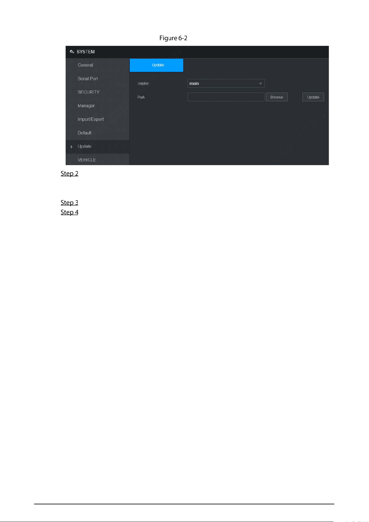
134
Update
Select the chip list that suits your actual needs.
To update system programs, select Main for the chip list.
To update the MCU firmware programs, select MCU for the chip list.
Click Browse and select the update file you want to use.
Click Update.
The system starts updating. You should login to the WEB interface again after updating.
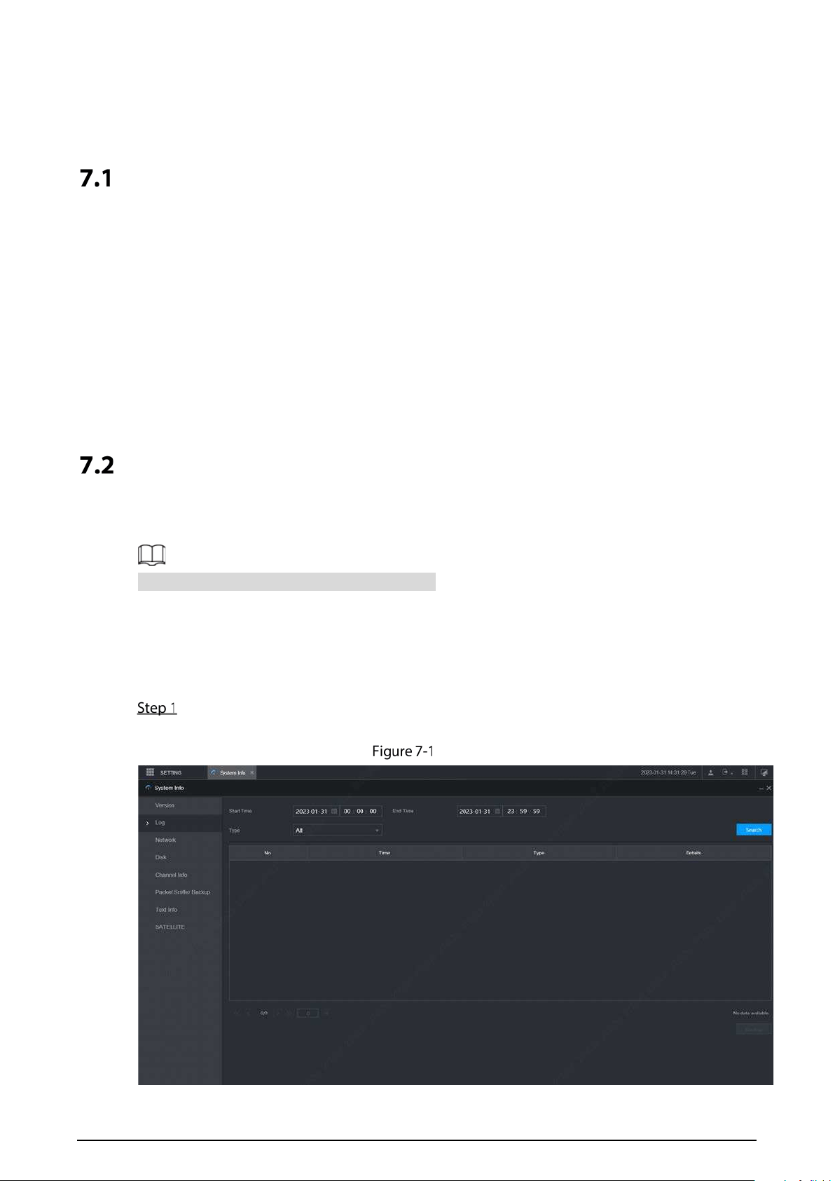
135
7 System Maintenance
Requirement for Maintenance
To keep the device running normally, it is recommended to manage, backup, and maintain the
device.
Check the monitoring screen of Device regularly.
Delete the unused user and group regularly.
Modify the user password every three months.
View the system logs regularly and analyze the data to handle the abnormalities timely.
Back up the system configurations regularly.
Reboot this device regularly.
Upgrade firm wares regularly.
System Information
You can view device version information, logs, network information, HDD information, channel
information, satellite information, and MAC information.
For version information, see “6.1 System Version”.
7.2.1 Log
You can search, view, and back up the logs to local PC.
Select SETTING > System Info > Log.
The Log interface is displayed. See Figure 7-1.
Log
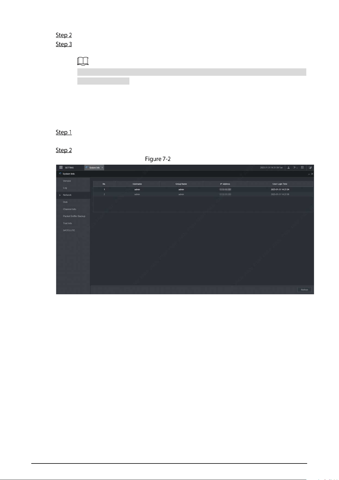
136
Set up Start Time, End Time, and Type.
Click Search.
The searched logs are displayed.
Select the log that you want to back up, and then click Backup. You can select the save path
to save the log to PC.
7.2.2 Network Info
You can view IP information of the logged in device.
Select SETTING > System Info > Network. The Network interface is displayed. See Figure
7-2.
Click Refresh and the latest network information is displayed.
Network
7.2.3 Disk
You can view the disk information of the device, including device name, physical position, health
status, and free space.
Select SETTING > System Info > Disk. The Disk interface is displayed. See Figure 7-3.
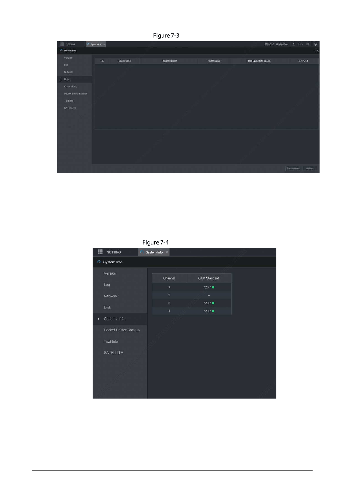
137
Disk
7.2.4 Channel Info
You can view the channel information.
Select SETTING > System Info > Channel Info. The Channel Info interface is displayed. See Figure
7-4.
Channel Info
7.2.5 Satellite Info
You can view the satellite positioning information such as module status, positioning status, latitude
and longitude, and search results.
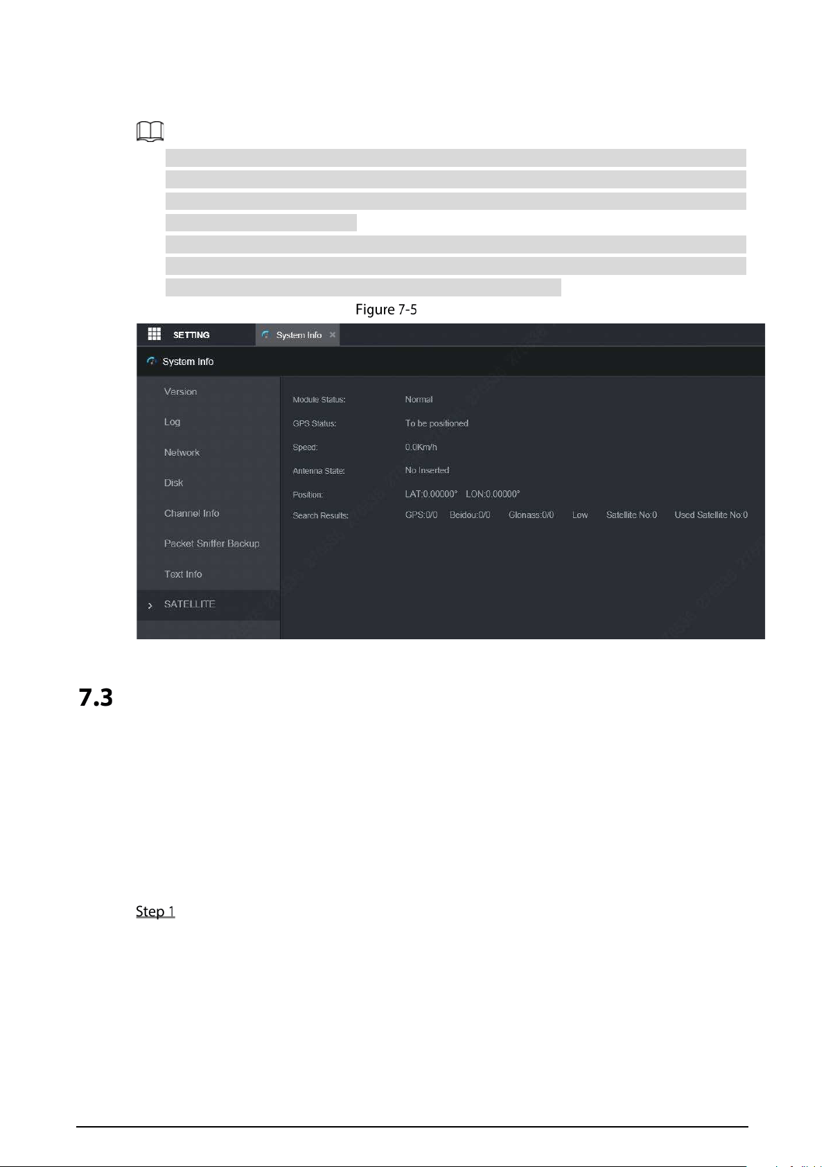
138
Select SETTING > System Info > Satellite. The Satellite interface is displayed. See Figure 7-5.
Click Refresh and the latest satellite information is displayed.
If the GPS module status indicates normal and does not position within five minutes, the GPS
module automatically resets and re-positions. When the positioning information is obtained
again, the GPS module reset times is up to 20, or the device is restarted, you can view the GPS
module reset records in the log.
When the GPS module is short-circuited for more than 10 seconds, the module status is
abnormal and the GPS module is automatically powered off and no longer powered on. After
the device is restarted, the GPS module will be powered on again.
Satellite
Automatic Maintenance
You can configure the automatic maintenance settings such as auto reboot, auto deleting old files,
auto booting up, auto shutdown, and delay for auto shutdown.
7.3.1 Auto Reboot
Once the device is running for a long time, you can set to automatically reboot the device at idle time.
After configuring auto reboot, when the device is working, it reboots according to the schedule.
Select SETTING > System > Manager.
The Manager interface is displayed. See Figure 7-6.
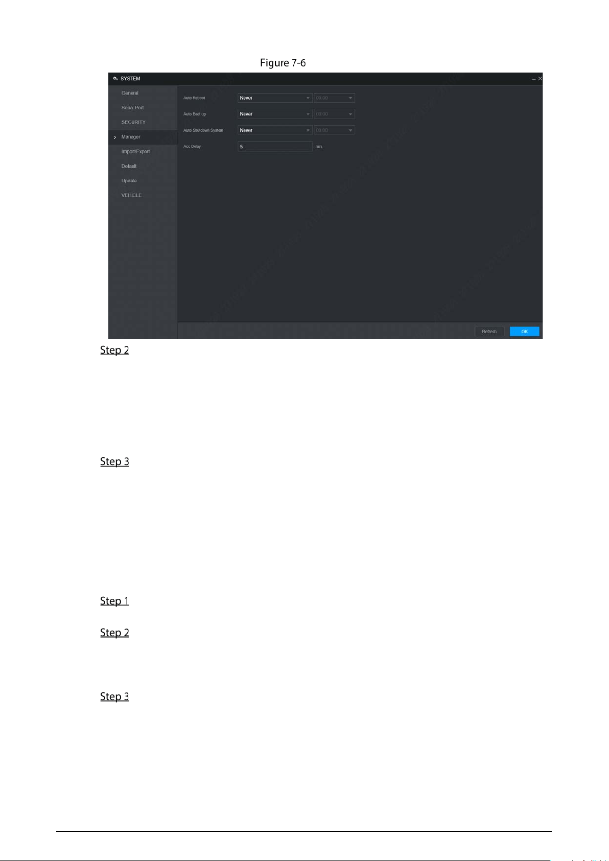
139
Manager
Select the strategy of auto restart.
Select Never, and the device will never restart automatically.
Select Every Day, set the device restart time, and the device will restart automatically
at that time point.
Select Monday to Sunday, set the device restart time, and the device will restart
automatically at that time point every week. If Sunday and 01:00 are selected, the
device will restart automatically at 1:00 every Sunday.
Click OK.
7.3.2 Auto Boot up
After configuring auto start, the device starts automatically at the scheduled time point. If you turn
the vehicle key to ACC before the configured auto start time, the device starts immediately. When
the documentation is powered off, the device will shut down as per the scheduled auto delay for
shutdown.
Select SETTING > System > Manager.
The Manager interface is displayed.
Select the strategy of auto start.
Select Never, and the device will never start automatically.
Select Every Day and set the time. When you turn the vehicle key to ACC before this
time point, the device starts immediately.
Click OK.
7.3.3 Auto Shutdown System
After configuring auto shutdown, the device automatically shuts down according to the ACC power
off time and auto boot up setting.

140
If you have set the time for auto start, there are two situations when the ACC is powered off: If
the system time is between the auto start time and auto shutdown time, the device is turned off
at the configured time point. If the system time is before the auto start time or after the auto
shutdown time, the device is turned off immediately.
If the auto booting up is not set, when the ACC is disconnected, the Device shuts down at the
scheduled time.
Select SETTING > System > Manager.
The Manager interface is displayed.
Select the strategy of auto shutdown.
Select Never, and the device will never shut down automatically.
Select Every Day and set the time. The system will shut down as per the ACC power off
time and auto start setting.
Select Every Day for Auto Shutdown, and then enter the specific time.
Click OK.
7.3.4 Acc Delay
After configuring delay for auto shutdown, when ACC is disconnected, the device shuts down as per
the settings of delay for auto shutdown.
If you enter a delay value that is not 0, the device automatically shuts down after the preset
delay.
If you enter 0, the device shuts down as per the auto shutdown settings without delay.
Select SETTING > System > Manager.
The Manager interface is displayed.
Configure the ACC delay for shutdown.
The value ranges from 0 through 65535. The fault value is 5.
Click OK.
Backup and Restore
You can back up or restore the web configurations and restore to default settings.
7.4.1 Backing up Configurations
You can back up all the configurations of web.
Select SETTING > System > Import/Export.
The Import/Export interface is displayed. See Figure 7-7.
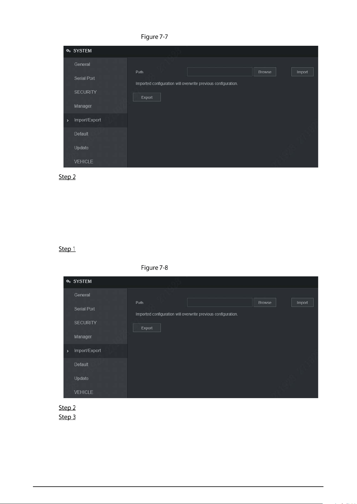
141
Import/Export (1)
Click Export, and select the backup path.
The system starts backing up configurations.
7.4.2 Importing Configurations
You can use the backed up configurations to quickly configure the device and restore the device
configurations.
Select SETTING > System > Import/Export.
The Import/Export interface is displayed. See Figure 7-8.
Import/Export (2)
Click Browse, and then select the backup file you want to import.
Click Import.
The system pops up the reboot message. Click OK, the system starts importing the
configurations and reboot the device after importing is completed.
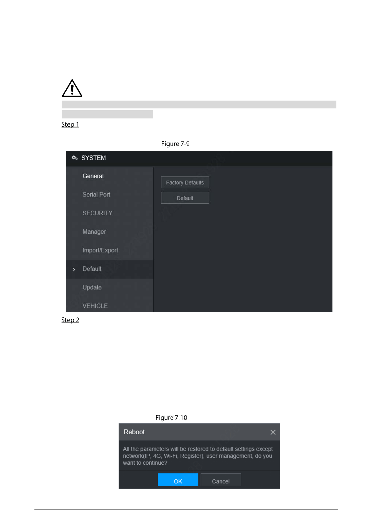
142
7.4.3 Restoring to Default
You can restore the system to default configurations or the factory default. Only the user with the
default & upgrade authorities can do this.
The corresponding functions will be restored to the factory settings, and your current configurations
will be lost. Proceed with caution.
Select SETTING > System > Default.
The Default interface is displayed. See Figure 7-9.
Default
Select the check box of the options that you want to restore to the factory default.
Default: Click Default, and the Reboot dialog box is popped up. See Figure 7-10. Then
click OK. All configurations other than user name, password, security questions and
device IP are restored to the default configuration of the device.
Factory Default: Click Factory Default, and the Reboot dialog box is displayed. See
Figure 7-11. Then click OK, and the system restarts. After the device is restarted, the
system will restore to factory defaults, and the device requires initialization again.
Proceed with caution.
When there is a user operating on the local interface, the factory default settings
cannot be performed until the local user log out.
Reboot (1)
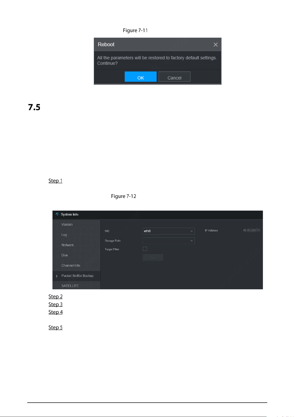
143
Reboot (2)
Network Sniffer
The packet data can be provided to the developers or engineers to analyze the network usage status.
Prerequisites
The device being captured is connected to an external backup device.
Procedure
Select SETTING > Info > Packet Sniffer Backup.
The Packet Sniffer Backup interface is displayed, see Figure 7-12.
Packet Sniffer Backup
Packet Sniffer Backup
Select the Ethernet card and save path.
Select the Target Filter check box, and then enter the IP address that you want to filter.
Click Start.
The system starts the sniffer, and the data will be stored to the external backup device.
Click Stop.
The Message dialog box is displayed, see Figure 7-13.

144
Message
Click OK or Cancel to complete the task.
Click OK to download the files locally, which can be viewed in the storage path.
Click Cancel to stop downloading.

145
8 Operating by DSS
Beside from web, you can also remotely log in to the Recorder from Digital Surveillance System
(DSS). For details, see the manual of DSS.

146
9 FAQ
If your questions cannot be answer by the following contents, please contact your local service
engineer or the service of our Headquarters for help. We can guide you to solve this problem.
1) Q: Disconnect the constant electricity but the Recorder is still working.
A: Possible causes:
The default 5-minute shutdown delay is effective.
The UPS setting provides constant power supply to the Recorder when the lithium
battery voltage is above 7V.
ACC is connected.
2) Q: The Recorder gives squeal after it is boot up.
A: Possible causes:
Connecting to the display and being too close to the camera.
A single channel interface or a large-image multi-channel interface. The first channel
of sound comes from a local source.
3) Q: The interface shows that no SIM card is detected.
A: Possible causes:
SIM card not inserted.
Micro SIM card reversely inserted with its notch facing outward. Follow instructions on
the label to insert the SIM card.
SIM card is damaged.
4) Q: DVR cannot boot up properly.
A: Possible causes:
The input power is not correct; the input voltage is too low or too high.
Poor contact in the input power cable or incorrect wiring.
HDD is damaged or poor contact between the HDD carrier and HDD.
Main board is damaged.
5) Q: DVR automatically reboots or frequently crashes.
A: Possible causes:
Input voltage is not stable or too low.
The Recorder is not properly installed, which result in poor contact between
components.
Poor heat dissipation and too many dusts result in poor working environment for the
Recorder.
Hardware malfunction.
6) Q: HDD cannot be detected after rebooting.
A: Possible causes:

147
HDD not installed.
Poor contact between the HDD carrier and HDD.
HDD is damaged.
7) Q: Blank screen in a channel of the display
A: Possible causes:
A camera is damaged. Replace the damaged camera.
The connection wire is damaged. Replace the damaged connection wire.
8) Q: No video output from single-channel, multiple-channel or all-channel.
A: Possible causes:
Program is not compatible. Please upgrade to the correct version.
Brightness value of all channel is 0. Please restore to default setting.
No video input signal or the signal is too weak.
Channel protection or screen protection is configured.
Hardware malfunction.
9) Q: Real-time video image is abnormal, such as color and brightness is distorted.
A: Possible causes:
NTSC and PAL settings are not correct, and the image becomes black and white.
Recorder and monitor resistance is not compatible.
Video network transmission distance is too far or transmission line signal attenuation
is too much.
NVR color or brightness settings are not correct.
10) Q: No recorded video can be found in local playback.
A: Possible causes:
Poor contact between the HDD carrier and HDD.
HDD is damaged.
Upgraded program is not compatible.
The recording file that you want to search has been overlapped.
The recorded file is not opened.
11) Q: Video is distorted in local search.
A: Possible causes:
Video quality setting is too low.
Program read error, bit data is too small, and there is full of mosaic in the screen.
Please firstly try to restart the DVR to solve this problem.
Disk error
Hardware malfunction.
12) Q: The monitor has no sound.
A: Possible causes:

148
It is not an active speaker.
Audio cable is damaged.
Hardware malfunction.
13) Q: There is audio under monitoring state but no audio under playback state.
A: Possible causes:
Audio function is not enabled.
The corresponding channel does not connect to the camera. Playback is not
continuous when the screen is blue.
14) Q: System time is not correct.
A: Possible causes:
Setting is not correct.
Poor battery contact or voltage is too low.
Crystal oscillator is poor.
15) Q: USB backup error.
A: Possible causes:
Too much data which occupies CPU resources. Please stop recording first and then
begin backup.
Backup Recorder is not compatible.
Backup Recorder is damaged.
The backup Recorder features high power and needs separate power supply.
16) Q: Alarm function does not work.
A: Possible causes:
Alarm setting is not correct.
Alarm cable connection is not correct.
Alarm input signal is not correct.
There are two loops connected to one alarm Recorder.
17) Q: Messy channel display.
A: Possible causes:
Incorrect selection of camera type. Auto switch is recommended.
The camera is damaged.
18) Q: Record storage time is not enough.
A: Possible causes:
Low camera quality, dirty lens, camera installed against the light, or iris not properly
adjusted caused large big rate.
HDD capacity is not enough.
The HDD is damaged.
19) Q: No 3G/4G dial-up. No dial-up IP,

149
A: Possible causes:
Check if the SIM card is normal.
Check if the SIM card is not in service.
Check if the 3G/4G antenna is connected as intended.
Check if the 3G/4G signals are strong enough.
Try out with another SIM card.
20) Q: 3G/4G platform is not online.
A: Possible causes:
Check if 3G/4G dial-up is normal.
Check if local active registration is correctly set up.
Check if the sever terminal is correctly set up.
21) Q: No GPS data.
A: Possible causes:
Check if the GPS antenna is connected as intended.
Make sure the GPS antenna is in a place where signals are not blocked.
22) Q: GPS drifting and produces speed for no reason.
A: Possible causes:
Weak GPS signal.
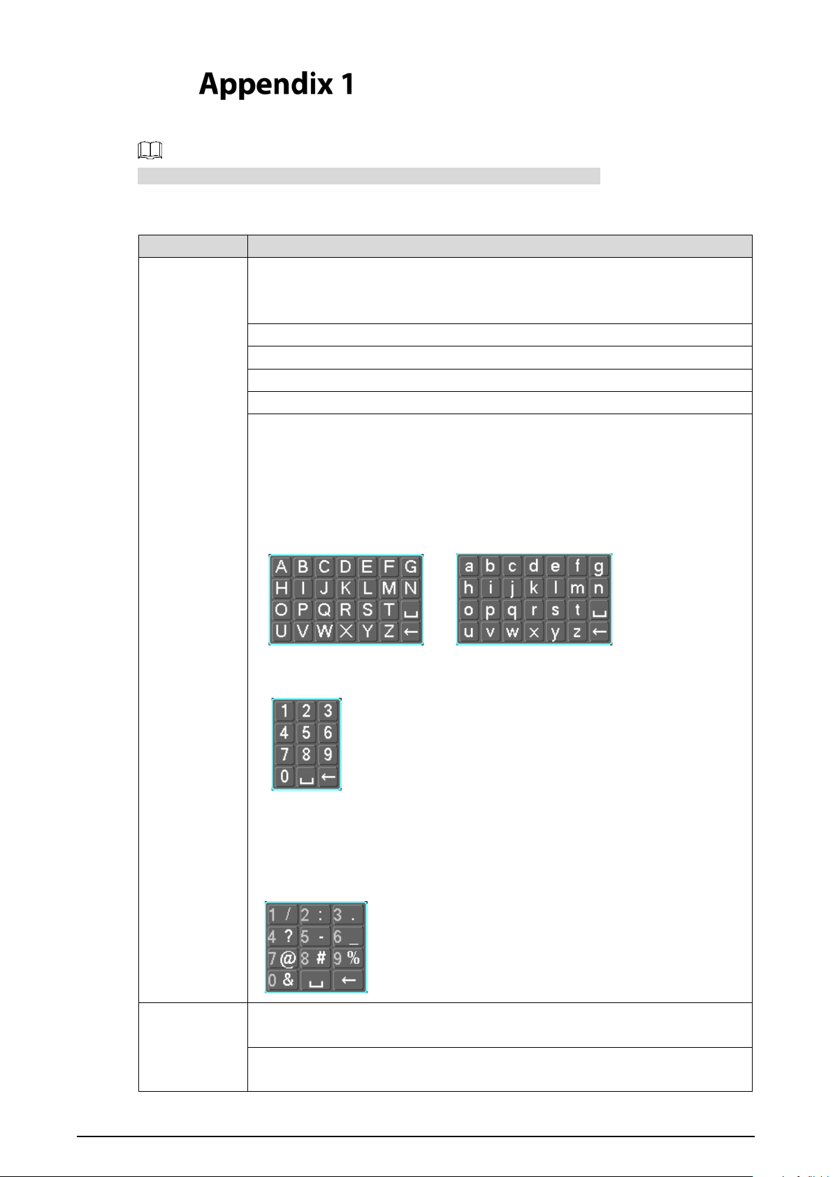
150
Mouse Operations
The operations are based on the considerations for right-handed users.
Beside the operations from the front panel and remote control, you can also use mouse to
operate menus. Insert the mouse to the USB port of the Recorder.
Operation Function
Click the left
mouse button
If the user has not logged into the system, the password box is displayed first.
During real-time monitoring, click the left mouse button to go to the main
menu.
When you have selected one menu item, click it to view menu content.
Implement the operations indicated on the control.
Change the status of the check box.
Click the combo box, the drop-down list is displayed.
In text box, click the corresponding button on the panel to enter a numeral,
punctuation, English character (small/capitalized), or Chinese. Left-click the
symbol on the panel to complete value input; represents backspace, and_
represents space.
In English input mode: Click _ to enter a space, and click to delete the
previous character.
In numeral input mode: Click _ to delete all numbers, and click to delete the
previous number.
In special characters input mode: For the numbers and characters on the soft
panel, press the numbers on the front panel to enter the corresponding
characters, for example, press 1 means entering /. You can also directly use the
mouse to click to enter the characters.
Double-click
the left mouse
button
The special operation to perform a specific action. For example, double-click the
recorded video file to start playback.
In multi-image, double-click a channel image to display it in full screen.
Double-click again to restore the previous multi-window screen.

151
Right-click
In the real-time monitoring screen, right-click on the screen, the shortcut menu
is displayed. You can configure the settings including multi-image mode (related
to the number of channels of the Recorder), PTZ control, color setting, recording
search, recording control, alarm output, and main menu. To use PTZ control and
color setting apply to the images corresponding to the pointer. If it was
multi-image mode before settings, the system auto switches to the single
images of corresponding channels first.
Do not save the setting and exit the current menu.
Wheel button
In numeral input box, rotate the wheel button to increase or decrease the
numeral value.
Switch between items in the combo box.
Page up or page down.
Move Select and move a control of the current coordinates or one of its items.
Drag Box select an area and set up area overlap.

152
HDD Capacity Calculation
In the first installation of the HDD, check whether the HDD is already installed. To install IDE
HDD, pay attention to the jumper of the HDD.
HDD capacity calculation formula:
Total capacity (M) = Channel number × Demand time length (hour) × HDD capacity occupied
per hour (M/hour)
Recording time calculation formula:
Recording time (hour) = HDD total capacity (M)
HDD capacity occupied per hour (M/hour) × Channel number
The Recorder adopts MPEG4/H.264 compression technology, which features a large dynamic
range. Therefore, when calculating HDD capacity, you should accord to the bit rate to evaluate
the file size generated per hour from each channel.

153
Cybersecurity Recommendations
Cybersecurity is more than just a buzzword: it's something that pertains to every device that is
connected to the internet. IP video surveillance is not immune to cyber risks, but taking basic steps
toward protecting and strengthening networks and networked appliances will make them less
susceptible to attacks. Below are some tips and recommendations on how to create a more secured
security system.
Mandatory actions to be taken for basic equipment network security:
1. Use Strong Passwords
Please refer to the following suggestions to set passwords:
The length should not be less than 8 characters;
Include at least two types of characters; character types include upper and lower case
letters, numbers and symbols;
Do not contain the account name or the account name in reverse order;
Do not use continuous characters, such as 123, abc, etc.;
Do not use overlapped characters, such as 111, aaa, etc.;
2. Update Firmware and Client Software in Time
According to the standard procedure in Tech-industry, we recommend to keep your
equipment (such as NVR, DVR, IP camera, etc.) firmware up-to-date to ensure the
system is equipped with the latest security patches and fixes. When the equipment is
connected to the public network, it is recommended to enable the "auto-check for
updates" function to obtain timely information of firmware updates released by the
manufacturer.
We suggest that you download and use the latest version of client software.
"Nice to have" recommendations to improve your equipment network security:
1. Physical Protection
We suggest that you perform physical protection to equipment, especially storage devices. For
example, place the equipment in a special computer room and cabinet, and implement
well-done access control permission and key management to prevent unauthorized personnel
from carrying out physical contacts such as damaging hardware, unauthorized connection of
removable equipment (such as USB flash disk, serial port), etc.
2. Change Passwords Regularly
We suggest that you change passwords regularly to reduce the risk of being guessed or cracked.
3. Set and Update Passwords Reset Information Timely
The equipment supports password reset function. Please set up related information for
password reset in time, including the end user's mailbox and password protection questions. If
the information changes, please modify it in time. When setting password protection questions,
it is suggested not to use those that can be easily guessed.
4. Enable Account Lock
The account lock feature is enabled by default, and we recommend you to keep it on to
guarantee the account security. If an attacker attempts to log in with the wrong password
several times, the corresponding account and the source IP address will be locked.
5. Change Default HTTP and Other Service Ports
We suggest you to change default HTTP and other service ports into any set of numbers
between 1024~65535, reducing the risk of outsiders being able to guess which ports you are

154
using.
6. Enable HTTPS
We suggest you to enable HTTPS, so that you visit Web service through a secure communication
channel.
7. Enable Allowlist
We suggest you to enable allowlist function to prevent everyone, except those with specified IP
addresses, from accessing the system. Therefore, please be sure to add your computer's IP
address and the accompanying equipment's IP address to the allowlist.
8. MAC Address Binding
We recommend you to bind the IP and MAC address of the gateway to the equipment, thus
reducing the risk of ARP spoofing.
9. Assign Accounts and Privileges Reasonably
According to business and management requirements, reasonably add users and assign a
minimum set of permissions to them.
10. Disable Unnecessary Services and Choose Secure Modes
If not needed, it is recommended to turn off some services such as SNMP, SMTP, UPnP, etc., to
reduce risks.
If necessary, it is highly recommended that you use safe modes, including but not limited to the
following services:
SNMP: Choose SNMP v3, and set up strong encryption passwords and authentication
passwords.
SMTP: Choose TLS to access mailbox server.
FTP: Choose SFTP, and set up strong passwords.
AP hotspot: Choose WPA2-PSK encryption mode, and set up strong passwords.
11. Audio and Video Encrypted Transmission
If your audio and video data contents are very important or sensitive, we recommend that you
use encrypted transmission function, to reduce the risk of audio and video data being stolen
during transmission.
Reminder: encrypted transmission will cause some loss in transmission efficiency.
12. Secure Auditing
Check online users: we suggest that you check online users regularly to see if the device is
logged in without authorization.
Check equipment log: By viewing the logs, you can know the IP addresses that were used
to log in to your devices and their key operations.
13. Network Log
Due to the limited storage capacity of the equipment, the stored log is limited. If you need to
save the log for a long time, it is recommended that you enable the network log function to
ensure that the critical logs are synchronized to the network log server for tracing.
14. Construct a Safe Network Environment
In order to better ensure the safety of equipment and reduce potential cyber risks, we
recommend:
Disable the port mapping function of the router to avoid direct access to the intranet
devices from external network.
The network should be partitioned and isolated according to the actual network needs. If
there are no communication requirements between two sub networks, it is suggested to
use VLAN, network GAP and other technologies to partition the network, so as to achieve
the network isolation effect.

155
Establish the 802.1x access authentication system to reduce the risk of unauthorized access
to private networks.
It is recommended that you enable your device's firewall or blocklist and allowlist feature
to reduce the risk that your device might be attacked.