Loading ...
Loading ...
Loading ...
10
7. If the Target Top is fitted with a Refrigeration Cabinet, the cabinet must NOT be installed in an
explosive environment, open air or exposed to rain. The following considerations should be made;-
Cabinet must be located away from heat sources (radiators ovens and other heat generating
kitchen appliances) and direct sunlight.
Must be protected from draughts.
Air circulation around the condensing unit must not be obstructed.
NOTE: Only non-combustible materials can be used in close proximity to this appliance.
* For additional clearances information refer to Refrigeration Cabinet Installation and
Operation Manual supplied with Refrigeration Cabinet.
NOTE:
Leg Stand Model (RN8100G-LS), will require assembly. Refer to 'Leg Stand Models Only'
information shown below for assembly instructions.
All Models are delivered completely assembled. No further assembly is required, with the
exception of Leg Stand Model (RN8100G-LS), this will require assembly. Refer to Fitting of
Adjustable Feet / Rear Rollers to Leg Stand Units' information below for assembly
instructions.
Appliance rear leg housings can be fitted with:-
Adjustable feet to assist with appliance levelling on uneven floors.
Rear rollers to enable appliance to be easily moved for positioning and cleaning
purposes.
Optional Accessories (Refer to Replacement Parts List)
Plinth Kit. For installation details, refer to instructions supplied with each kit.
1. Remove centre casting from target top using casting removal tool and remove 2 half plate castings.
2. Remove all fire bricks from target top.
3. Lower target top onto it’s rear face.
4. Attach four hob legs to leg mounting positions on underside of target top. Secure each leg hand
tight.
5. Align four round cut out holes on base tray with four hob legs already fitted to target top (Ensure
base tray is orientated with sloping edge of base tray facing front of unit.
6. Slot base tray onto four hob legs and push fully home.
7. Secure base tray to hob legs by screwing two front adjustable feet supplied, into base of front hob
legs. Secure each adjustable foot hand tight.
8. The two rear leg housings can be fitted with either adjustable feet or rollers. (See Fig 1).
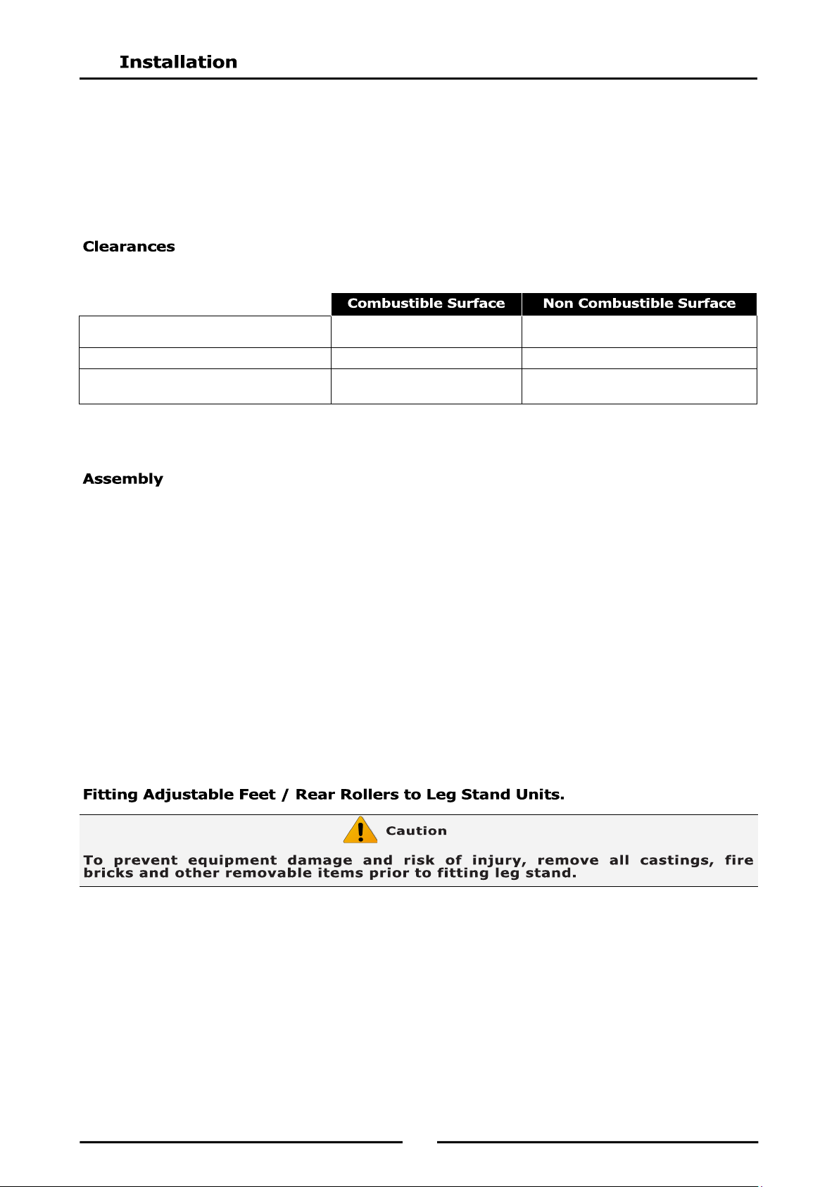
-B/-CB/-LS models:
Left/Right Hand Side
50mm
0mm
Rear 50mm 0mm
-RB model:
Sides / Rear
75mm
75mm *
Loading ...
Loading ...
Loading ...